RF-6000E/EW RepeaterRF-6000E/EW RepeaterM i c r o w a v e R e p e a t e r S y s t e m s
World Headquarters
39 Grand Canyon Lane
San Ramon,
CA 94583 USA
President
Frank Martens
Phone
925.901.0103
Fax
925.901.0403
Peninsula Engineering
Solutions, inc. may
change specifications as
necessary to meet
industry requirements. Website www.peninsulaengineering.com Email [email protected]
no power lines no shelters no roads
just great microwave reliability.
RF-6000E/EW RepeaterRF-6000E/EW Repeater
Website www.peninsulaengineering.com Email [email protected] 01
Table of Contents
APPLICATIONS
FEATURES
TECHNICAL SUMMARY
1. GENERAL
2. FUNCTIONAL DESCRIPTION
Basic Repeater
Amplifiers
Directional Couplers
AGC/ALC Adjustment
Linear Gain Adjustment
Power Supply
3. ALARMS
4. LICENSING
5. ORDERING
6. INSTALLATION
General
Power Wiring
DC Power
7. TESTS
General
Test Equipment
Application of Power
Antenna Isolation Measurement
Antenna Orientation, AGC/ALC set
and Output Measurement
8. MAINTENANCE
Routine Maintenance
Administration Requirements
Trouble Location
Amplifier Replacement, Out of Service
Amplifier Replacement, In Service
Return Procedure
APPENDIX A
Antenna System
02
02
03
09
09
09
09
18
18
18
18
18
22
22
28
28
28
28
28
28
28
31
32
33
33
33
34
34
34
34
35
37
37
Applications
• Low-cost, highly reliable 6-GHz microwave through repeater for extending range of or clearing obstructed microwave radio paths.
• Excellent performance with analog, digital, or video microwave radios; channel capacity to 2400 FDM, 2016 PCM
(3 DS3 or 135/140 Mb/s) or multiple video.
• Compatible with any manufacturer’s 6-GHz radio terminal.
• Solar power compatible -- economical in thin routes and remote locations.
Features
• RF output power up to +28 dBm analog, +21 dBm digital.
• Power consumption only 2.3 amperes at 12 Vdc for regular-power-duplex operation.
• Solar powered, ac powered, or powered by primary cells.
• Compact and lightweight -- ideally suited for remote sites that do not have access roads or commercial power.
• Environmentally protected aluminum, weathertight, lockable cabinet. No extra environmental shelter required in most installation.
Suitable for use at unimproved sites anywhere in the world -- Alaska to Saudi Arabia.
• Internally protected duplex, frequency diversity, and three-way or “Y junction” configurations available.
• Only one active element per channel, the internally redundant linear amplifier.
• AGC/ALC provided to correct input fades and reduce overload.
• In the case of single duplex configuration, amplifiers can be replaced without disrupting service.
• RMAS-100 Alarm system (optional) can remotely monitor repeater.
• Equipped with directional couplers for in-service RF output power measurements.
• No frequency conversion -- received signal is filtered, amplified, and re-radiated.
• Very reliable, greater than 85,000 hours MTBF for duplex.
• Available as a self-contained RF repeater for use with customer-furnished antenna and power equipment or as a complete package
including repeater, antenna, electric panels, battery charger and batteries.
RF-6000E/EW RepeaterRF-6000E/EW Repeater
Website www.peninsulaengineering.com Email [email protected] 02
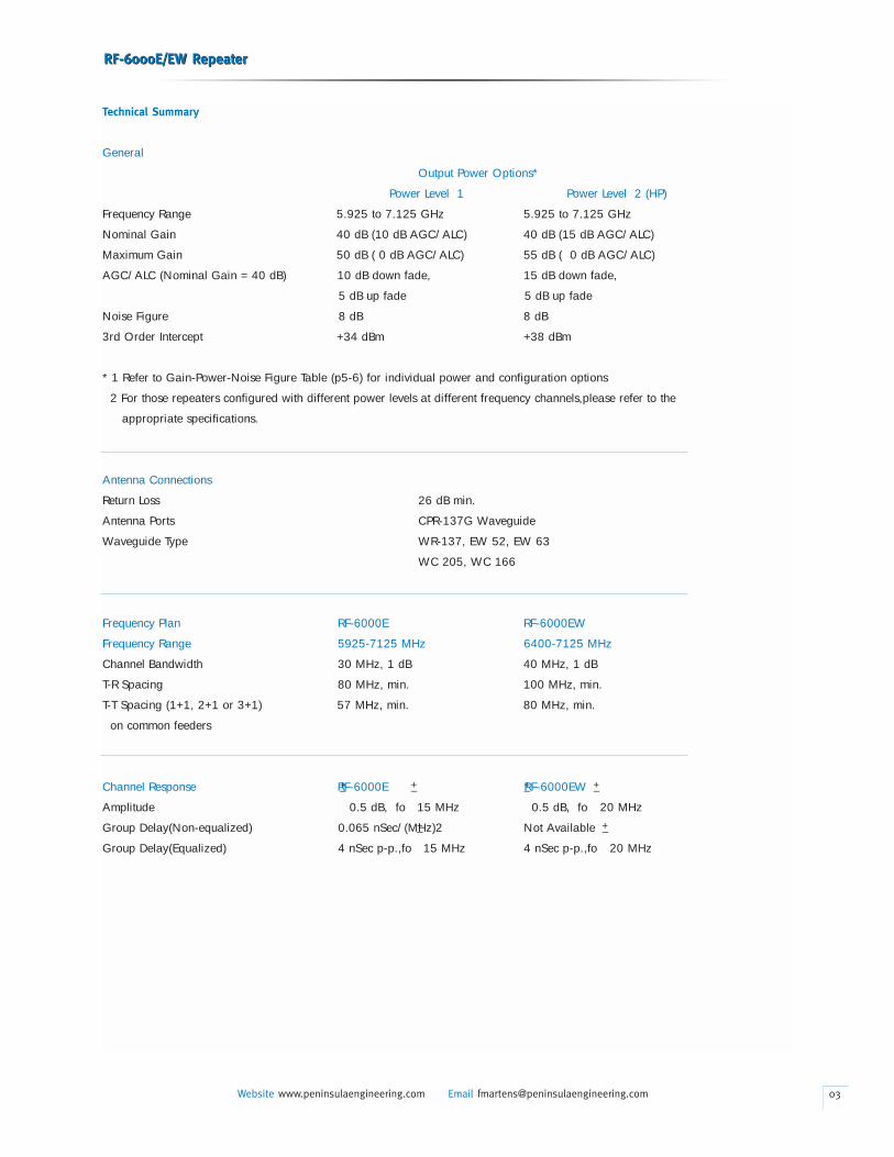
Technical Summary
General
Output Power Options*
Power Level 1 Power Level 2 (HP)
Frequency Range 5.925 to 7.125 GHz 5.925 to 7.125 GHz
Nominal Gain 40 dB (10 dB AGC/ALC) 40 dB (15 dB AGC/ALC)
Maximum Gain 50 dB ( 0 dB AGC/ALC) 55 dB ( 0 dB AGC/ALC)
AGC/ALC (Nominal Gain = 40 dB) 10 dB down fade, 15 dB down fade,
5 dB up fade 5 dB up fade
Noise Figure 8 dB 8 dB
3rd Order Intercept +34 dBm +38 dBm
* 1 Refer to Gain-Power-Noise Figure Table (p5-6) for individual power and configuration options
2 For those repeaters configured with different power levels at different frequency channels,please refer to the
appropriate specifications.
Antenna Connections
Return Loss 26 dB min.
Antenna Ports CPR-137G Waveguide
Waveguide Type WR-137, EW 52, EW 63
WC 205, WC 166
Frequency Plan RF-6000E RF-6000EW
Frequency Range 5925-7125 MHz 6400-7125 MHz
Channel Bandwidth 30 MHz, 1 dB 40 MHz, 1 dB
T-R Spacing 80 MHz, min. 100 MHz, min.
T-T Spacing (1+1, 2+1 or 3+1) 57 MHz, min. 80 MHz, min.
on common feeders
Channel Response RF-6000E RF-6000EW
Amplitude 0.5 dB, fo 15 MHz 0.5 dB, fo 20 MHz
Group Delay(Non-equalized) 0.065 nSec/(MHz)2 Not Available
Group Delay(Equalized) 4 nSec p-p.,fo 15 MHz 4 nSec p-p.,fo 20 MHz
RF-6000E/EW RepeaterRF-6000E/EW Repeater
Website www.peninsulaengineering.com Email [email protected] 03
+_ +_
+_ +_
+_ +_
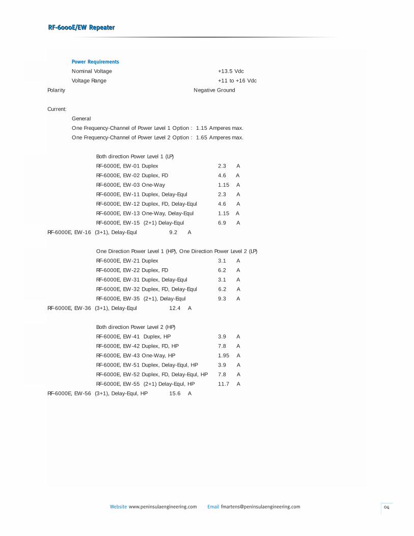
Power Requirements
Nominal Voltage +13.5 Vdc
Voltage Range +11 to +16 Vdc
Polarity Negative Ground
Current:
General
One Frequency-Channel of Power Level 1 Option : 1.15 Amperes max.
One Frequency-Channel of Power Level 2 Option : 1.65 Amperes max.
Both direction Power Level 1 (LP)
RF-6000E, EW-01 Duplex 2.3 A
RF-6000E, EW-02 Duplex, FD 4.6 A
RF-6000E, EW-03 One-Way 1.15 A
RF-6000E, EW-11 Duplex, Delay-Equl 2.3 A
RF-6000E, EW-12 Duplex, FD, Delay-Equl 4.6 A
RF-6000E, EW-13 One-Way, Delay-Equl 1.15 A
RF-6000E, EW-15 (2+1) Delay-Equl 6.9 A
RF-6000E, EW-16 (3+1), Delay-Equl 9.2 A
One Direction Power Level 1 (HP), One Direction Power Level 2 (LP)
RF-6000E, EW-21 Duplex 3.1 A
RF-6000E, EW-22 Duplex, FD 6.2 A
RF-6000E, EW-31 Duplex, Delay-Equl 3.1 A
RF-6000E, EW-32 Duplex, FD, Delay-Equl 6.2 A
RF-6000E, EW-35 (2+1), Delay-Equl 9.3 A
RF-6000E, EW-36 (3+1), Delay-Equl 12.4 A
Both direction Power Level 2 (HP)
RF-6000E, EW-41 Duplex, HP 3.9 A
RF-6000E, EW-42 Duplex, FD, HP 7.8 A
RF-6000E, EW-43 One-Way, HP 1.95 A
RF-6000E, EW-51 Duplex, Delay-Equl, HP 3.9 A
RF-6000E, EW-52 Duplex, FD, Delay-Equl, HP 7.8 A
RF-6000E, EW-55 (2+1) Delay-Equl, HP 11.7 A
RF-6000E, EW-56 (3+1), Delay-Equl, HP 15.6 A
RF-6000E/EW RepeaterRF-6000E/EW Repeater
Website www.peninsulaengineering.com Email [email protected] 04
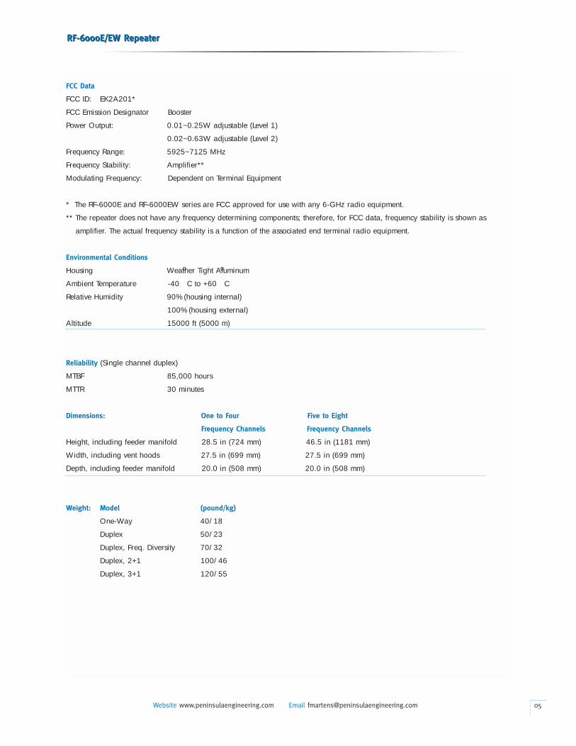
FCC Data
FCC ID: EK2A201*
FCC Emission Designator Booster
Power Output: 0.01~0.25W adjustable (Level 1)
0.02~0.63W adjustable (Level 2)
Frequency Range: 5925~7125 MHz
Frequency Stability: Amplifier**
Modulating Frequency: Dependent on Terminal Equipment
* The RF-6000E and RF-6000EW series are FCC approved for use with any 6-GHz radio equipment.
** The repeater does not have any frequency determining components; therefore, for FCC data, frequency stability is shown as
amplifier. The actual frequency stability is a function of the associated end terminal radio equipment.
Environmental Conditions
Housing Weather Tight Aluminum
Ambient Temperature -40 C to +60 C
Relative Humidity 90% (housing internal)
100% (housing external)
Altitude 15000 ft (5000 m)
Reliability (Single channel duplex)
MTBF 85,000 hours
MTTR 30 minutes
Dimensions: One to Four Five to Eight
Frequency Channels Frequency Channels
Height, including feeder manifold 28.5 in (724 mm) 46.5 in (1181 mm)
Width, including vent hoods 27.5 in (699 mm) 27.5 in (699 mm)
Depth, including feeder manifold 20.0 in (508 mm) 20.0 in (508 mm)
Weight: Model (pound/kg)
One-Way 40/18
Duplex 50/23
Duplex, Freq. Diversity 70/32
Duplex, 2+1 100/46
Duplex, 3+1 120/55
RF-6000E/EW RepeaterRF-6000E/EW Repeater
Website www.peninsulaengineering.com Email [email protected] 05
o o
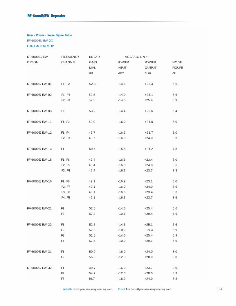
Gain - Power - Noise Figure Table
RF-6000E /EW-XX
FOR FM/FSK/MSK*
RF-6000E /EW FREQUENCY LINEAR AGC/ALC ON *
OPTION CHANNEL GAIN POWER POWER NOISE
MIN. INPUT OUTPUT FIGURE
dB dBm dBm dB
RF-6000E/EW-01 F1, F2 52.8 -14.6 +25.4 6.6
RF-6000E/EW-02 F1, F4 52.5 -14.9 +25.1 6.6
F2, F3 52.5 -14.6 +25.4 6.9
RF-6000E/EW-03 F1 53.2 -14.4 +25.6 6.4
RF-6000E/EW-11 F1, F2 50.0 -16.0 +24.0 8.0
RF-6000E/EW-12 F1, F4 49.7 -16.3 +23.7 8.0
F2, F3 49.7 -16.0 +24.0 8.3
RF-6000E/EW-13 F1 50.4 -15.8 +24.2 7.8
RF-6000E/EW-15 F1, F6 49.4 -16.6 +23.4 8.0
F2, F5 49.4 -16.0 +24.0 8.6
F3, F4 49.4 -16.3 +23.7 8.3
RF-6000E/EW-16 F1, F8 49.1 -16.9 +23.1 8.0
F2, F7 49.1 -16.0 +24.0 8.9
F3, F6 49.1 -16.6 +23.4 8.3
F4, F5 49.1 -16.3 +23.7 8.6
RF-6000E/EW-21 F1 52.8 -14.6 +25.4 6.6
F2 57.8 -10.6 +29.4 6.6
RF-6000E/EW-22 F1 52.5 -14.6 +25.1 6.6
F2 57.5 -10.9 29.4 6.9
F3 52.5 -14.6 +25.4 6.9
F4 57.5 -10.9 +29.1 6.6
RF-6000E/EW-31 F1 50.0 -16.0 +24.0 8.0
F2 55.0 -12.0 +28.0 8.0
RF-6000E/EW-32 F1 49.7 -16.3 +23.7 8.0
F2 54.7 -12.0 +28.0 8.3
F3 49.7 -16.0 +24.0 8.3
RF-6000E/EW RepeaterRF-6000E/EW Repeater
Website www.peninsulaengineering.com Email [email protected] 06
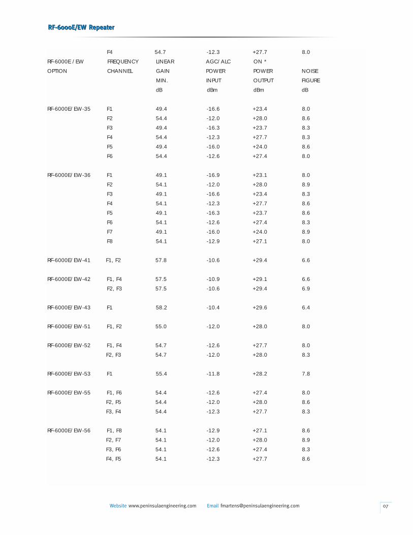
F4 54.7 -12.3 +27.7 8.0
RF-6000E /EW FREQUENCY LINEAR AGC/ALC ON *
OPTION CHANNEL GAIN POWER POWER NOISE
MIN. INPUT OUTPUT FIGURE
dB dBm dBm dB
RF-6000E/EW-35 F1 49.4 -16.6 +23.4 8.0
F2 54.4 -12.0 +28.0 8.6
F3 49.4 -16.3 +23.7 8.3
F4 54.4 -12.3 +27.7 8.3
F5 49.4 -16.0 +24.0 8.6
F6 54.4 -12.6 +27.4 8.0
RF-6000E/EW-36 F1 49.1 -16.9 +23.1 8.0
F2 54.1 -12.0 +28.0 8.9
F3 49.1 -16.6 +23.4 8.3
F4 54.1 -12.3 +27.7 8.6
F5 49.1 -16.3 +23.7 8.6
F6 54.1 -12.6 +27.4 8.3
F7 49.1 -16.0 +24.0 8.9
F8 54.1 -12.9 +27.1 8.0
RF-6000E/EW-41 F1, F2 57.8 -10.6 +29.4 6.6
RF-6000E/EW-42 F1, F4 57.5 -10.9 +29.1 6.6
F2, F3 57.5 -10.6 +29.4 6.9
RF-6000E/EW-43 F1 58.2 -10.4 +29.6 6.4
RF-6000E/EW-51 F1, F2 55.0 -12.0 +28.0 8.0
RF-6000E/EW-52 F1, F4 54.7 -12.6 +27.7 8.0
F2, F3 54.7 -12.0 +28.0 8.3
RF-6000E/EW-53 F1 55.4 -11.8 +28.2 7.8
RF-6000E/EW-55 F1, F6 54.4 -12.6 +27.4 8.0
F2, F5 54.4 -12.0 +28.0 8.6
F3, F4 54.4 -12.3 +27.7 8.3
RF-6000E/EW-56 F1, F8 54.1 -12.9 +27.1 8.6
F2, F7 54.1 -12.0 +28.0 8.9
F3, F6 54.1 -12.6 +27.4 8.3
F4, F5 54.1 -12.3 +27.7 8.6
RF-6000E/EW RepeaterRF-6000E/EW Repeater
Website www.peninsulaengineering.com Email [email protected] 07
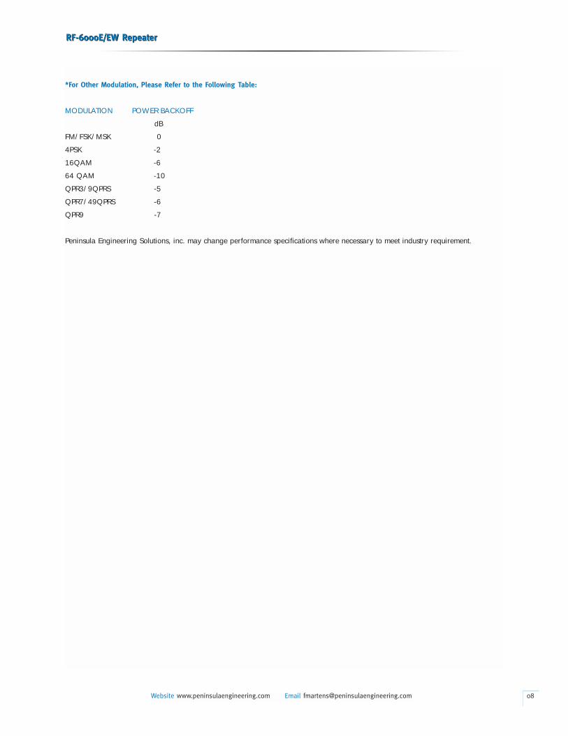
*For Other Modulation, Please Refer to the Following Table:
MODULATION POWER BACKOFF
dB
FM/FSK/MSK 0
4PSK -2
16QAM -6
64 QAM -10
QPR3/9QPRS -5
QPR7/49QPRS -6
QPR9 -7
Peninsula Engineering Solutions, inc. may change performance specifications where necessary to meet industry requirement.
RF-6000E/EW RepeaterRF-6000E/EW Repeater
Website www.peninsulaengineering.com Email [email protected] 08
1. GENERAL
• This Section provides information for the Peninsula
Engineering RF-6000E/EW, RF Repeater Assembly; hereinafter
referred to as the RF-6000E/EW. The RF-6000E/ EW
may be used with any manufacturer’s 6-GHz radio operating
in the 5.925-7.125 GHz frequency range to provide an
intermediate repeater.
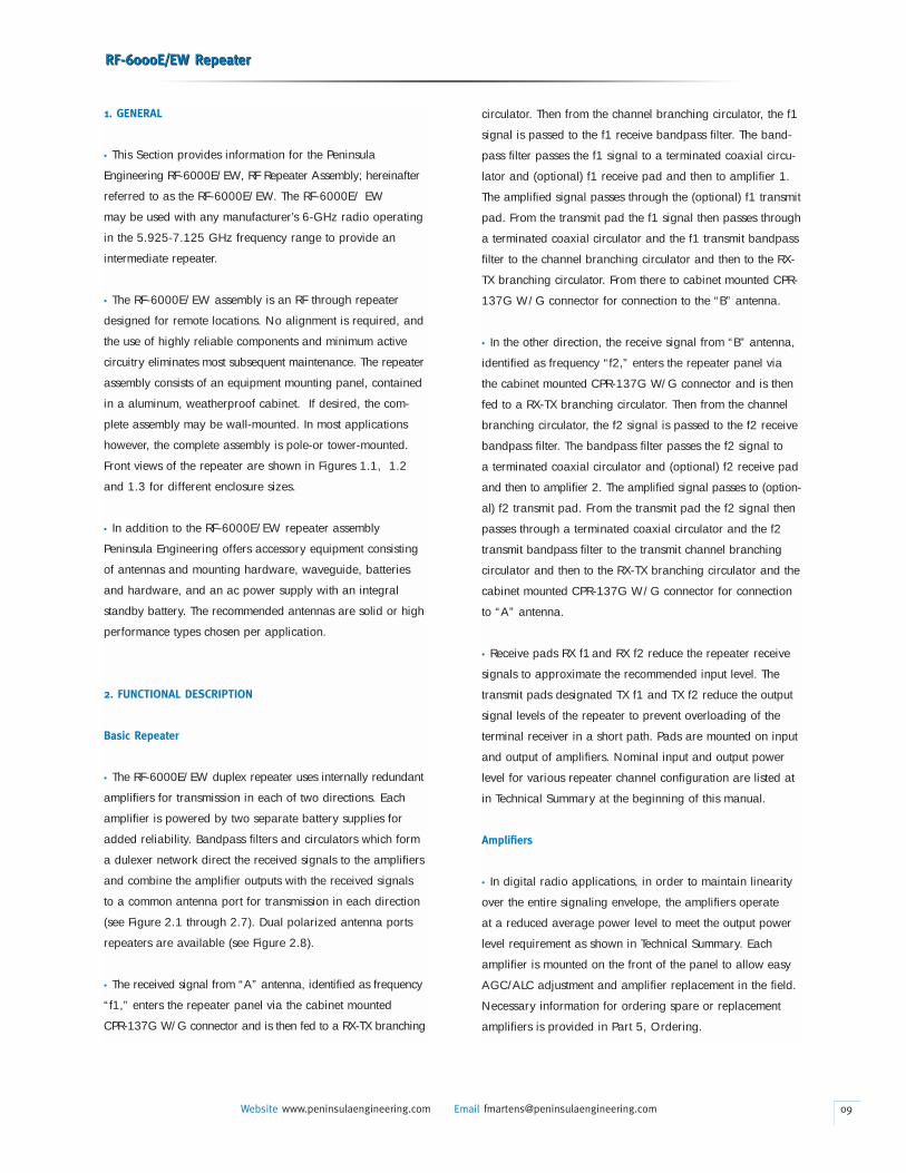
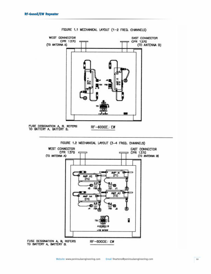
• The RF-6000E/EW assembly is an RF through repeater
designed for remote locations. No alignment is required, and
the use of highly reliable components and minimum active
circuitry eliminates most subsequent maintenance. The repeater
assembly consists of an equipment mounting panel, contained
in a aluminum, weatherproof cabinet. If desired, the com-
plete assembly may be wall-mounted. In most applications
however, the complete assembly is pole-or tower-mounted.
Front views of the repeater are shown in Figures 1.1, 1.2
and 1.3 for different enclosure sizes.
• In addition to the RF-6000E/EW repeater assembly
Peninsula Engineering offers accessory equipment consisting
of antennas and mounting hardware, waveguide, batteries
and hardware, and an ac power supply with an integral
standby battery. The recommended antennas are solid or high
performance types chosen per application.
2. FUNCTIONAL DESCRIPTION
Basic Repeater
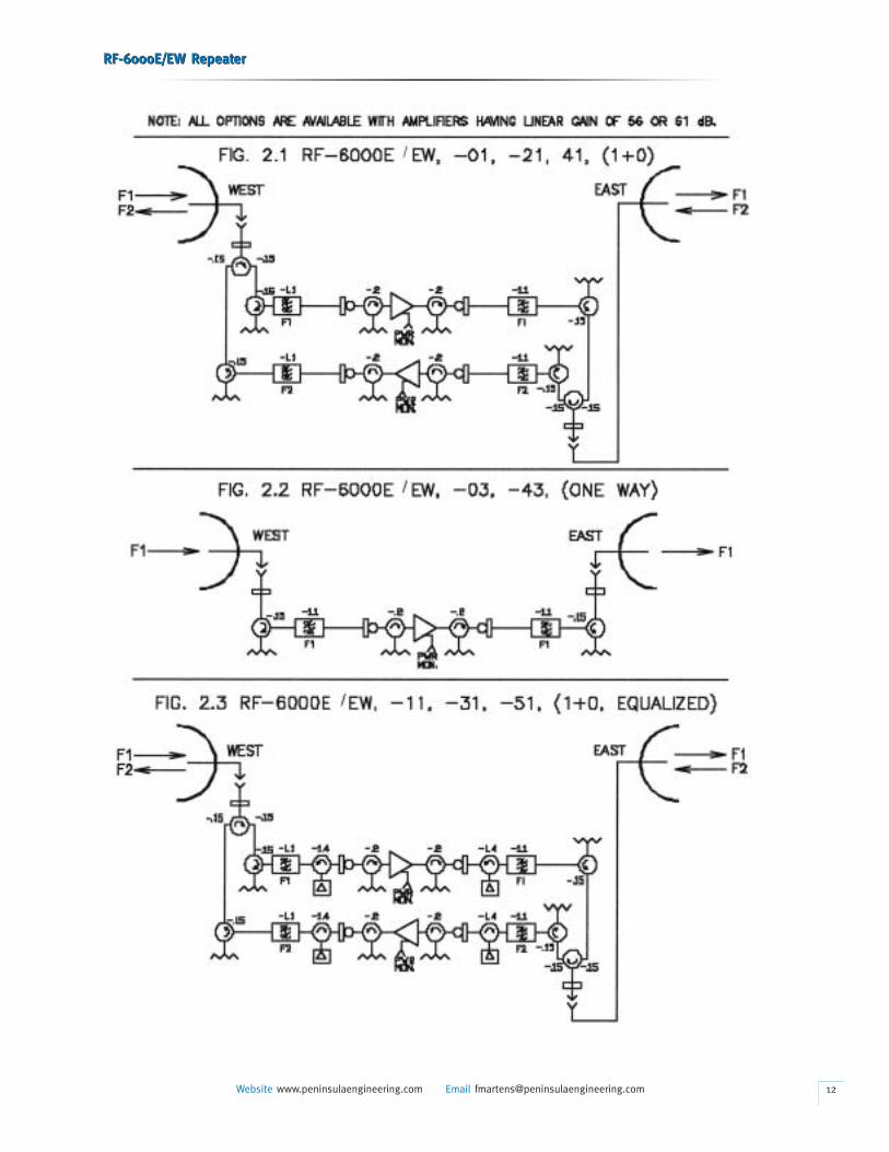
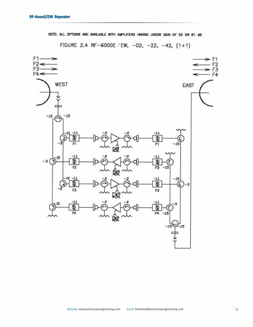
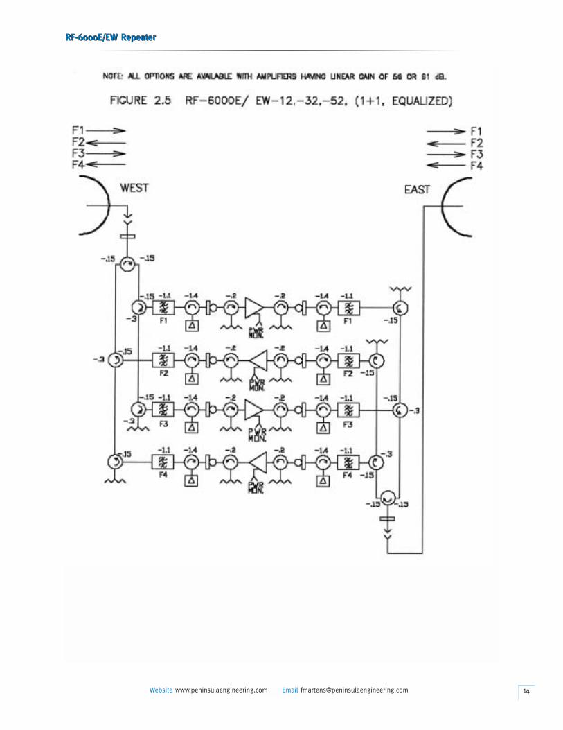
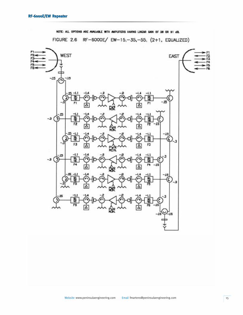
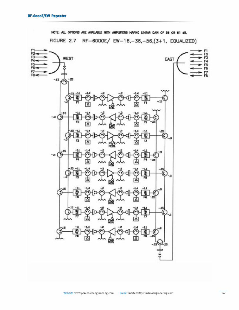
• The RF-6000E/EW duplex repeater uses internally redundant
amplifiers for transmission in each of two directions. Each
amplifier is powered by two separate battery supplies for
added reliability. Bandpass filters and circulators which form
a dulexer network direct the received signals to the amplifiers
and combine the amplifier outputs with the received signals
to a common antenna port for transmission in each direction
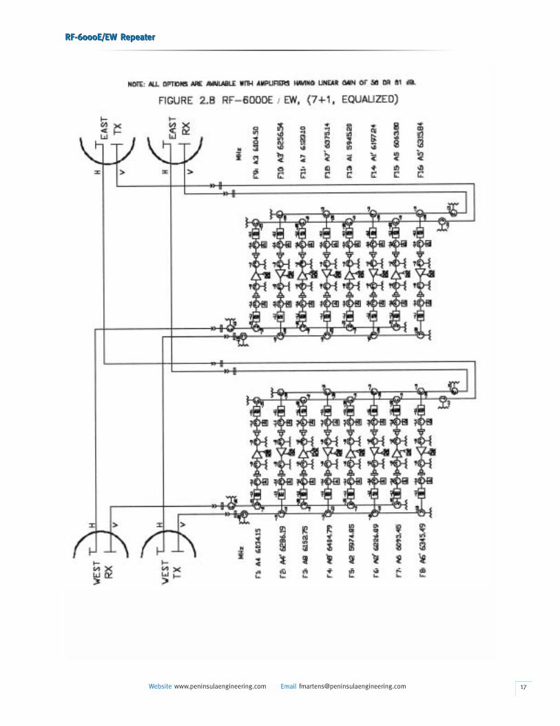
(see Figure 2.1 through 2.7). Dual polarized antenna ports
repeaters are available (see Figure 2.8).
• The received signal from “A” antenna, identified as frequency
“f1,” enters the repeater panel via the cabinet mounted
CPR-137G W/G connector and is then fed to a RX-TX branching
RF-6000E/EW RepeaterRF-6000E/EW Repeater
Website www.peninsulaengineering.com Email [email protected]
circulator. Then from the channel branching circulator, the f1
signal is passed to the f1 receive bandpass filter. The band-
pass filter passes the f1 signal to a terminated coaxial circu-
lator and (optional) f1 receive pad and then to amplifier 1.
The amplified signal passes through the (optional) f1 transmit
pad. From the transmit pad the f1 signal then passes through
a terminated coaxial circulator and the f1 transmit bandpass
filter to the channel branching circulator and then to the RX-
TX branching circulator. From there to cabinet mounted CPR-
137G W/G connector for connection to the “B” antenna.
• In the other direction, the receive signal from “B” antenna,
identified as frequency “f2,” enters the repeater panel via
the cabinet mounted CPR-137G W/G connector and is then
fed to a RX-TX branching circulator. Then from the channel
branching circulator, the f2 signal is passed to the f2 receive
bandpass filter. The bandpass filter passes the f2 signal to
a terminated coaxial circulator and (optional) f2 receive pad
and then to amplifier 2. The amplified signal passes to (option-
al) f2 transmit pad. From the transmit pad the f2 signal then
passes through a terminated coaxial circulator and the f2
transmit bandpass filter to the transmit channel branching
circulator and then to the RX-TX branching circulator and the
cabinet mounted CPR-137G W/G connector for connection
to “A” antenna.
• Receive pads RX f1 and RX f2 reduce the repeater receive
signals to approximate the recommended input level. The
transmit pads designated TX f1 and TX f2 reduce the output
signal levels of the repeater to prevent overloading of the
terminal receiver in a short path. Pads are mounted on input
and output of amplifiers. Nominal input and output power
level for various repeater channel configuration are listed at
in Technical Summary at the beginning of this manual.
Amplifiers
• In digital radio applications, in order to maintain linearity
over the entire signaling envelope, the amplifiers operate
at a reduced average power level to meet the output power
level requirement as shown in Technical Summary. Each
amplifier is mounted on the front of the panel to allow easy
AGC/ALC adjustment and amplifier replacement in the field.
Necessary information for ordering spare or replacement
amplifiers is provided in Part 5, Ordering.
09
RF-6000E/EW RepeaterRF-6000E/EW Repeater
Website www.peninsulaengineering.com Email [email protected] 10
RF-6000E/EW RepeaterRF-6000E/EW Repeater
Website www.peninsulaengineering.com Email [email protected] 11
RF-6000E/EW RepeaterRF-6000E/EW Repeater
Website www.peninsulaengineering.com Email [email protected] 12
RF-6000E/EW RepeaterRF-6000E/EW Repeater
Website www.peninsulaengineering.com Email [email protected] 13
RF-6000E/EW RepeaterRF-6000E/EW Repeater
Website www.peninsulaengineering.com Email [email protected] 14
RF-6000E/EW RepeaterRF-6000E/EW Repeater
Website www.peninsulaengineering.com Email [email protected] 15
RF-6000E/EW RepeaterRF-6000E/EW Repeater
Website www.peninsulaengineering.com Email [email protected] 16
RF-6000E/EW RepeaterRF-6000E/EW Repeater
Website www.peninsulaengineering.com Email [email protected] 17
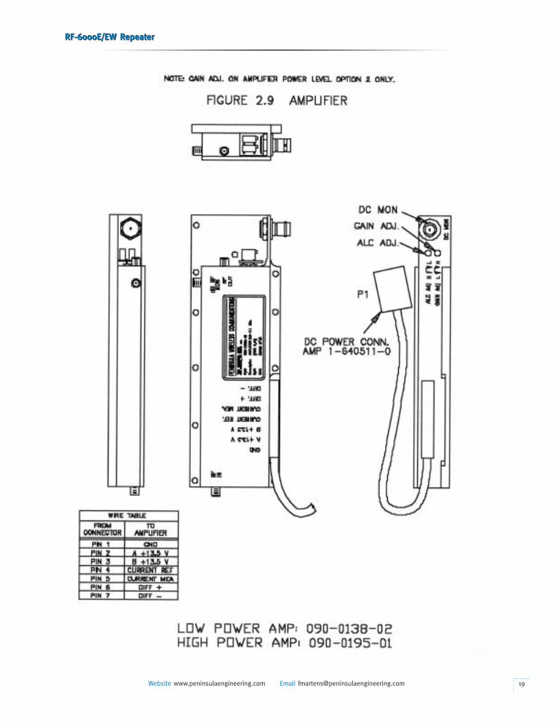
Directional Couplers
• Directional couplers, built into the amplifiers, provide signal
monitor points (Figure 2.9). These allow in-service measurement
of transmit output power. The monitor points are calibrated
to indicate actual RF output power at the antenna connector.
When measuring transmit power, the power meter reading
obtained, plus the loss (in dB) marked at the amplifier monitor
point, minus the branching loss (in dB) marked on the panel,
equals actual transmit output power.
For example:
(1) Power meter indication = +5.0dBm
(2) Loss marked at monitor = 18.2dB
(3) Branching Loss = -2.2dB
--------------------
Output Power = +21.0dBm
AGC/ALC Adjustment
• There is a field-adjustable potentiometer on the amplifier
(shown in Figure 2.9). The repeater output level and nominal
gain is adjusted by AGC/ALC potentiometer.
Linear Gain Adjustment
• On the amplifier with higher output power (Power Level 2),
there is a second field-adjustable potentiometer for linear
gain adjustment to limit its maximum gain.
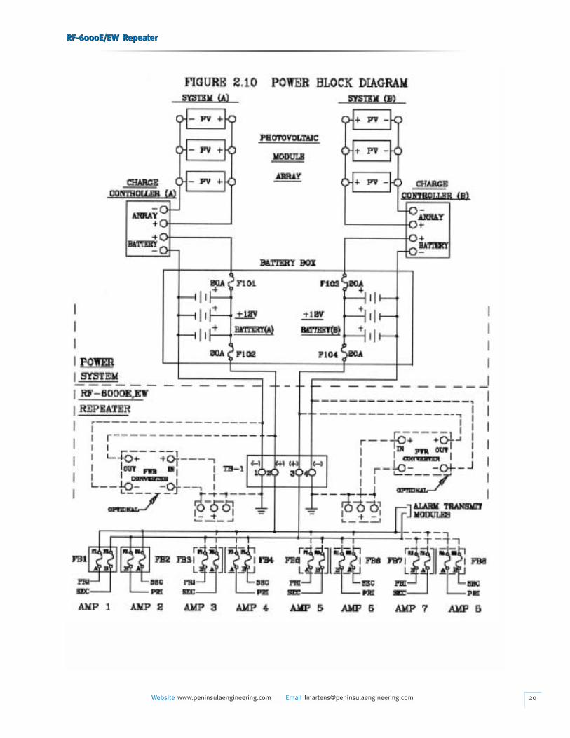
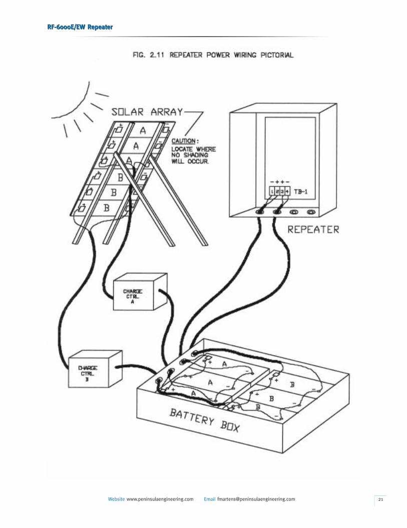
Power Supply
• The only active elements in the RF-6000E, EW assembly
are the amplifiers which operate from a +13.5 Vdc source.
Current requirements are 1.15 Amperes per Power Level 1
amplifier and 1.9 Amperes per Power Level 2 amplifier. The
repeater assembly may be powered from solar panels/batter-
ies, primary cells only, or from an ac/dc supply with standby
battery (shown in Figures 2.10 and 2.11).
• Storage batteries and solar cell panels are selected on the basis
of the average insulation and temperature range at the site. The
batteries are engineered to provide the required reserve capac-
ity across the temperature range and during periods when the
output from the solar panels is low or not available. Controllers
RF-6000E/EW RepeaterRF-6000E/EW Repeater
Website www.peninsulaengineering.com Email [email protected]
are used with the solar panels to efficiently charge the batteries
without overcharging. Peninsula Engineering can determine
the solar and battery capacity. The location of the site should
be specified when requesting assistance.
• In areas where commercial power is available, an ac power
supply can be provided. Although one ac power supply will
provide ample current to power all amplifiers, dual AC power
supplies are recommended for higher reliability. The dual AC
power supply system also contains two charge controllers and
two sets of standby battery to provide power during AC power
failures. Each battery is float charged while the power supply
is on and has 100 amp-hours as standard capacity. Additional
batteries can be purchased if the system requirement needs.
• In locations where commercial power is not available and
solar panel charging is impractical, primary cell batteries
capable of powering an RF-6000E/EW repeater in excess
of a year are available. In such applications, the battery
installation should be given an environmental shelter accord-
ing to the manufactures recommendations.
3. ALARMS
• The RF-6000E/EW repeater can be provided with an optional
alarm system to remotely monitor the repeater site. Conditions
that are typically monitored are listed below:
Standard Telemetry:
a) A and B Battery Voltage
b) Battery Temperature
Standard Trip Points:
c) A and B Battery Major Alarm (2)
d) East and West RF Output Low (2)
e) Amplifier Alarm
f) Cabinet Door Open
g) Feedline pressure low
h) 6 Each User Points, Strappable:
Closed or Open = Alarm
• The alarms are relayed back to the terminal through the use
of a low rate telemetry signal directly modulated on the RF in a
non-interfering fashion. Alarms are visually displayed on the
terminal receiver unit. Alarm contact closure outputs are avail-
able for input to standard microwave supervisory systems.
18
RF-6000E/EW RepeaterRF-6000E/EW Repeater
Website www.peninsulaengineering.com Email [email protected] 19
RF-6000E/EW RepeaterRF-6000E/EW Repeater
Website www.peninsulaengineering.com Email [email protected] 20
RF-6000E/EW RepeaterRF-6000E/EW Repeater
Website www.peninsulaengineering.com Email [email protected] 21
4. LICENSING
• FCC ID: EK2A201
5. ORDERING
• The RF-6000E/EW RF Repeater Assembly is ordered by
specifying the system model number RF-6000E/ EW-XX
(Tables 5.1 and 5.2). Attenuators are provided by specifying
their part numbers. Transmission engineering must be com-
pleted before ordering because the necessary attenuator
values are determined from the path calculations. Part numbers
are listed in Table 5.3.
• When doing the initial system layout of a radio hop which
includes a RF-6000E/EW RF Repeater Assembly, several
factors must be considered prior to ordering, to ensure correct
antenna connections.
(a) Terminal transmit-Repeater receive frequencies (F1 and
F2 or F1, F3 and F2, F4, etc).
RF-6000E/EW RepeaterRF-6000E/EW Repeater
Website www.peninsulaengineering.com Email [email protected]
(b) Physical mounting of RF-6000E/EW repeater on tower
(or crossarms) in relation to mounting of antennas.
• The RF-6000E/EW repeater may be factory-tuned so that
f1 RCV (A, LEFT) associates with the lower of the two frequen-
cies and f2 RCV (B, RIGHT) with the higher; or vice versa.
By comparing the factors listed above, correct antenna/coaxial
feeding connections will result. The equipment order must
specify all frequencies. For example:
f1 RCV = 6585MHz or f1 RCV = 6745MHz
f2 RCV = 6745MHz f2 RCV = 6585MHz
• Alarm system is optional. It should be ordered according
to Table 5.5.
• Orders should include a shipping destination and a billing
address. Upon receipt of your order Peninsula Engineering
returns an acknowledgment with the scheduled shipping date.
An equipment list, showing the equipment ordered and
shipped, is included with the shipment.
22
RF-6000E/EW RepeaterRF-6000E/EW Repeater
Website www.peninsulaengineering.com Email [email protected] 23
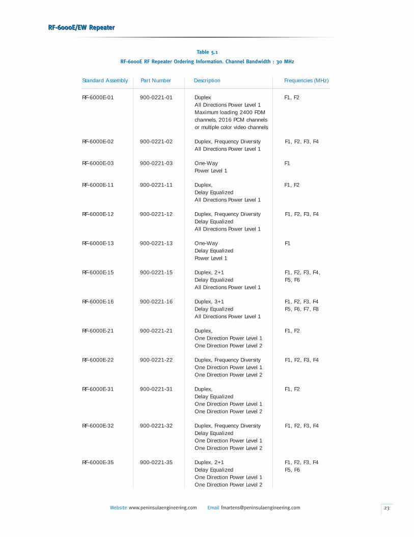
Table 5.1
RF-6000E RF Repeater Ordering Information. Channel Bandwidth : 30 MHz
Standard Assembly Part Number Description Frequencies (MHz)
RF-6000E-01 900-0221-01 Duplex F1, F2All Directions Power Level 1Maximum loading 2400 FDMchannels, 2016 PCM channelsor multiple color video channels
RF-6000E-02 900-0221-02 Duplex, Frequency Diversity F1, F2, F3, F4All Directions Power Level 1
RF-6000E-03 900-0221-03 One-Way F1Power Level 1
RF-6000E-11 900-0221-11 Duplex, F1, F2Delay EqualizedAll Directions Power Level 1
RF-6000E-12 900-0221-12 Duplex, Frequency Diversity F1, F2, F3, F4Delay EqualizedAll Directions Power Level 1
RF-6000E-13 900-0221-13 One-Way F1Delay EqualizedPower Level 1
RF-6000E-15 900-0221-15 Duplex, 2+1 F1, F2, F3, F4,Delay Equalized F5, F6All Directions Power Level 1
RF-6000E-16 900-0221-16 Duplex, 3+1 F1, F2, F3, F4Delay Equalized F5, F6, F7, F8All Directions Power Level 1
RF-6000E-21 900-0221-21 Duplex, F1, F2One Direction Power Level 1One Direction Power Level 2
RF-6000E-22 900-0221-22 Duplex, Frequency Diversity F1, F2, F3, F4One Direction Power Level 1One Direction Power Level 2
RF-6000E-31 900-0221-31 Duplex, F1, F2Delay EqualizedOne Direction Power Level 1One Direction Power Level 2
RF-6000E-32 900-0221-32 Duplex, Frequency Diversity F1, F2, F3, F4Delay EqualizedOne Direction Power Level 1One Direction Power Level 2
RF-6000E-35 900-0221-35 Duplex, 2+1 F1, F2, F3, F4Delay Equalized F5, F6One Direction Power Level 1One Direction Power Level 2
RF-6000E/EW RepeaterRF-6000E/EW Repeater
Website www.peninsulaengineering.com Email [email protected] 24
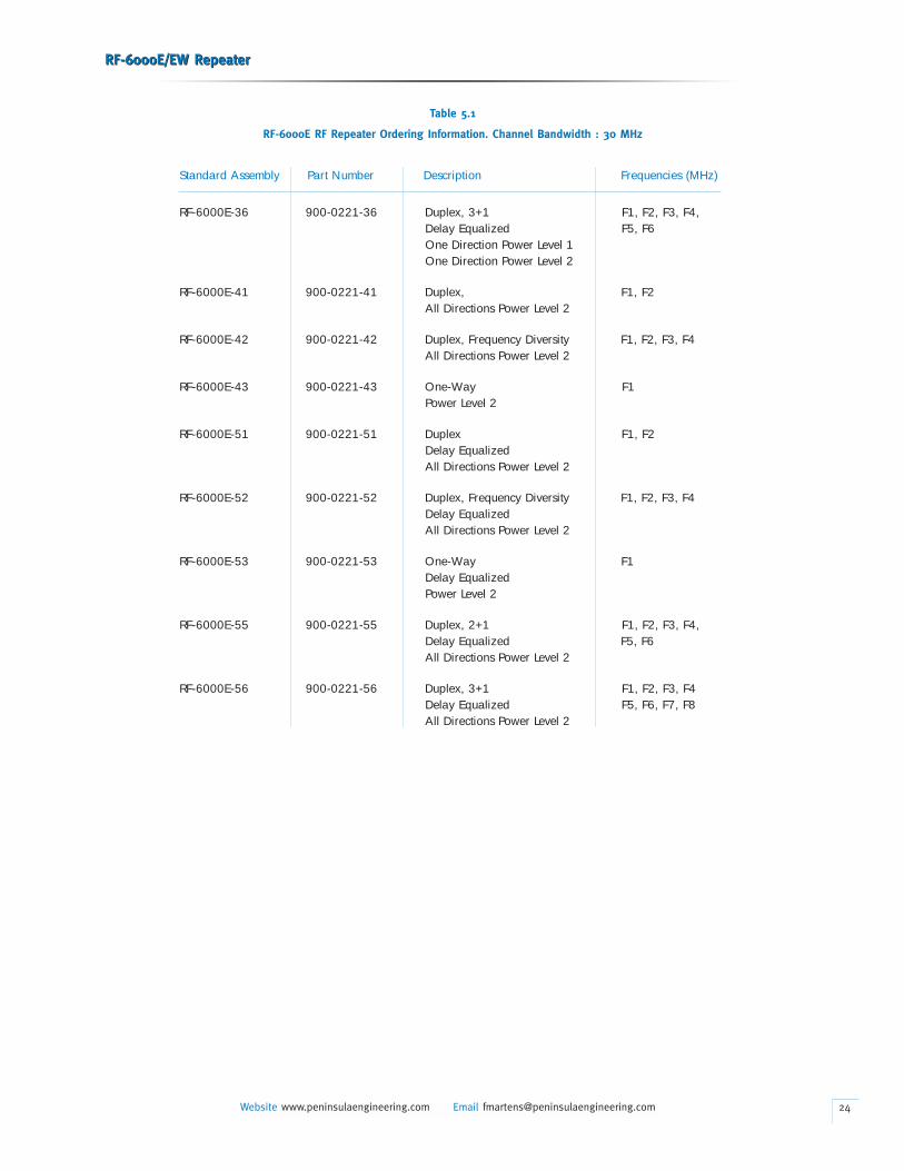
Table 5.1
RF-6000E RF Repeater Ordering Information. Channel Bandwidth : 30 MHz
Standard Assembly Part Number Description Frequencies (MHz)
RF-6000E-36 900-0221-36 Duplex, 3+1 F1, F2, F3, F4,Delay Equalized F5, F6One Direction Power Level 1One Direction Power Level 2
RF-6000E-41 900-0221-41 Duplex, F1, F2All Directions Power Level 2
RF-6000E-42 900-0221-42 Duplex, Frequency Diversity F1, F2, F3, F4All Directions Power Level 2
RF-6000E-43 900-0221-43 One-Way F1Power Level 2
RF-6000E-51 900-0221-51 Duplex F1, F2Delay Equalized All Directions Power Level 2
RF-6000E-52 900-0221-52 Duplex, Frequency Diversity F1, F2, F3, F4Delay Equalized All Directions Power Level 2
RF-6000E-53 900-0221-53 One-Way F1Delay Equalized Power Level 2
RF-6000E-55 900-0221-55 Duplex, 2+1 F1, F2, F3, F4,Delay Equalized F5, F6All Directions Power Level 2
RF-6000E-56 900-0221-56 Duplex, 3+1 F1, F2, F3, F4Delay Equalized F5, F6, F7, F8All Directions Power Level 2

RF-6000E/EW RepeaterRF-6000E/EW Repeater
Website www.peninsulaengineering.com Email [email protected] 25
Table 5.2
RF-6000EW RF Repeater Ordering Information. Channel Bandwidth : 40 MHz
Standard Assembly Part Number Description Frequencies (MHz)
RF-6000EW-01 900-0190-01 Duplex, F1, F2All Directions Power Level 1Maximum loading 2400 FDMchannels, 2016 PCM channelsor multiple color video channels
RF-6000EW-02 900-0190-02 Duplex, Frequency Diversity F1, F2, F3, F4All Directions Power Level 1
RF-6000EW-03 900-0190-03 One-Way F1Power Level 1
RF-6000EW-11 900-0190-11 Duplex, F1, F2Delay EqualizedAll Directions Power Level 1
RF-6000EW-12 900-0190-12 Duplex, Frequency Diversity F1, F2, F3, F4Delay EqualizedAll Directions Power Level 1
RF-6000EW-13 900-0190-13 One-Way F1Delay EqualizedPower Level 1
RF-6000EW-15 900-0190-15 Duplex, 2+1 F1, F2, F3, F4,Delay Equalized F5, F6All Directions Power Level 1
RF-6000EW-16 900-0190-16 Duplex, 3+1 F1, F2, F3, F4Delay Equalized F5, F6, F7, F8All Directions Power Level 1
RF-6000EW-21 900-0190-21 Duplex, F1, F2One Direction Power Level 1One Direction Power Level 2
RF-6000EW-22 900-0190-22 Duplex, Frequency Diversity F1, F2, F3, F4One Direction Power Level 1One Direction Power Level 2
RF-6000EW-31 900-0190-31 Duplex, F1, F2Delay EqualizedOne Direction Power Level 1One Direction Power Level 2
RF-6000EW-32 900-0190-32 Duplex, Frequency Diversity F1, F2, F3, F4Delay EqualizedOne Direction Power Level 1One Direction Power Level 2
RF-6000EW-35 900-0190-35 Duplex, 2+1 F1, F2, F3, F4Delay Equalized F5, F6One Direction Power Level 1One Direction Power Level 2
RF-6000E/EW RepeaterRF-6000E/EW Repeater
Website www.peninsulaengineering.com Email [email protected] 26
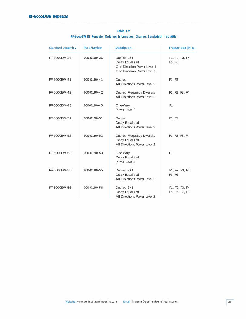
Table 5.2
RF-6000EW RF Repeater Ordering Information. Channel Bandwidth : 40 MHz
Standard Assembly Part Number Description Frequencies (MHz)
RF-6000EW-36 900-0190-36 Duplex, 3+1 F1, F2, F3, F4,Delay Equalized F5, F6One Direction Power Level 1One Direction Power Level 2
RF-6000EW-41 900-0190-41 Duplex, F1, F2All Directions Power Level 2
RF-6000EW-42 900-0190-42 Duplex, Frequency Diversity F1, F2, F3, F4All Directions Power Level 2
RF-6000EW-43 900-0190-43 One-Way F1Power Level 2
RF-6000EW-51 900-0190-51 Duplex F1, F2Delay Equalized All Directions Power Level 2
RF-6000EW-52 900-0190-52 Duplex, Frequency Diversity F1, F2, F3, F4Delay Equalized All Directions Power Level 2
RF-6000EW-53 900-0190-53 One-Way F1Delay Equalized Power Level 2
RF-6000EW-55 900-0190-55 Duplex, 2+1 F1, F2, F3, F4,Delay Equalized F5, F6All Directions Power Level 2
RF-6000EW-56 900-0190-56 Duplex, 3+1 F1, F2, F3, F4Delay Equalized F5, F6, F7, F8All Directions Power Level 2
RF-6000E/EW RepeaterRF-6000E/EW Repeater
Website www.peninsulaengineering.com Email [email protected] 27
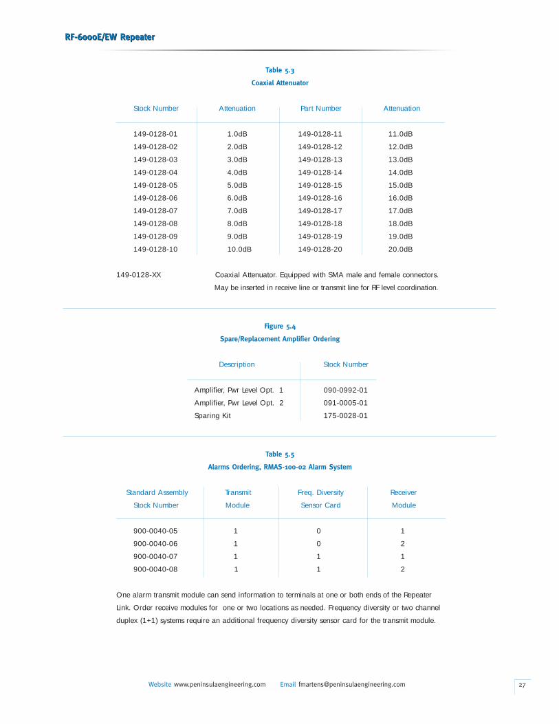
Table 5.3
Coaxial Attenuator
Stock Number Attenuation Part Number Attenuation
149-0128-01 1.0dB 149-0128-11 11.0dB
149-0128-02 2.0dB 149-0128-12 12.0dB
149-0128-03 3.0dB 149-0128-13 13.0dB
149-0128-04 4.0dB 149-0128-14 14.0dB
149-0128-05 5.0dB 149-0128-15 15.0dB
149-0128-06 6.0dB 149-0128-16 16.0dB
149-0128-07 7.0dB 149-0128-17 17.0dB
149-0128-08 8.0dB 149-0128-18 18.0dB
149-0128-09 9.0dB 149-0128-19 19.0dB
149-0128-10 10.0dB 149-0128-20 20.0dB
149-0128-XX Coaxial Attenuator. Equipped with SMA male and female connectors.
May be inserted in receive line or transmit line for RF level coordination.
Figure 5.4
Spare/Replacement Amplifier Ordering
Description Stock Number
Amplifier, Pwr Level Opt. 1 090-0992-01
Amplifier, Pwr Level Opt. 2 091-0005-01
Sparing Kit 175-0028-01
Table 5.5
Alarms Ordering, RMAS-100-02 Alarm System
Standard Assembly Transmit Freq. Diversity Receiver
Stock Number Module Sensor Card Module
900-0040-05 1 0 1
900-0040-06 1 0 2
900-0040-07 1 1 1
900-0040-08 1 1 2
One alarm transmit module can send information to terminals at one or both ends of the Repeater
Link. Order receive modules for one or two locations as needed. Frequency diversity or two channel
duplex (1+1) systems require an additional frequency diversity sensor card for the transmit module.
6. INSTALLATION
General
• When the RF-6000E/EW equipment is received, inspect it
carefully for damage. Claims for damage should be reported
directly to the transportation company involved immediately,
in accordance with their instructions.
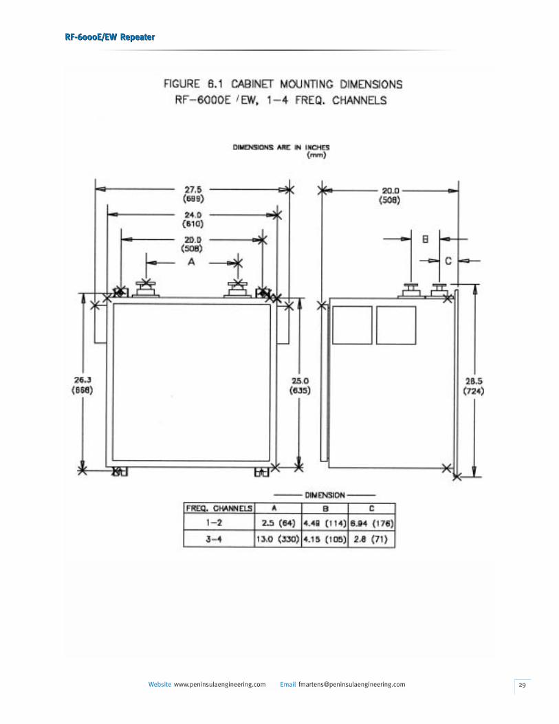
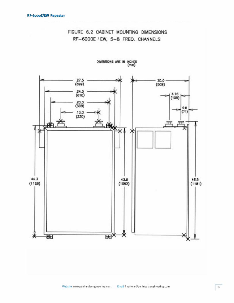
• The RF-6000E/EW assembly can be mounted on crossarms
on a wood-pole structure, a steel tower, or on a wall. At
extremely hot environment, eg. desert, shading from direct
sunshine may be required. The length of all power leads
should be limited and the wire size adequate to minimize the
voltage drop. The repeater assembly, battery boxes, solar
panels, and antennas should all be mounted before any wiring
is done. Mounting hole dimensions for the repeater enclosures
are shown in Figures 6.1 and 6.2.
• Prior to cutting to length and connecting the waveguide
feedlines, verify which repeater receive frequency associates
with each antenna port. The repeater receiving frequencies
and transmitting frequencies are marked on the top of repeater,
near waveguide manifolds.
• The waveguide feedlines are terminated in CPR-137G W/G
connectors. The RF-6000E/EW waveguide manifolds are
designed for pressurization up to 3 PSI (8 PSI test). Do Not
Use external pressure windows as they will prevent pressure
from entering the manifold. Otherwise water condensation
may occur inside the waveguide components.
Power Wiring
• Remove fuses from all fuse blocks (FB1, FB2,*******) on
repeater and remove the fuses (F101, F102, F103 and F104)
from the holders in the battery boxes if storage batteries are
used. The power leads can be brought into the repeater
housing through the 1/2 inch (13- mm)- non-metallic conduit
(NMT) fittings provided. Use paired 10-gauge (2.50-mm)
wire from the batteries to the repeater terminal block and from
the solar panels to the charge controller terminal block.
Connect the NEGATIVE leads from negative battery terminals
to terminals 1 and 4 of terminal block TB-1 as shown in
Figures 1.1. Then connect the POSITIVE leads from positive
battery terminals to terminals 2 and 3 of terminal block TB-1.
RF-6000E/EW RepeaterRF-6000E/EW Repeater
Website www.peninsulaengineering.com Email [email protected]
If a single ac supply is used, jumpers must be installed between
terminals 2 and 3 on the lower side of the terminal block
as shown in Figures 1.1. Note that the equipment uses a
negative ground.
DO NOT REPLACE ANY FUSE AT THIS TIME.
Application of power is covered in paragraph 7.03.
DC Power
• The repeater is normally powered from a dual battery sys-
tem designated “A” and “B.” The “A” battery is wired to power
the “A” side of the equipment. Similarly, the “B” battery is
wired to power the “B” side of the equipment. Standby power
switchover is accomplished within each amplifier. Each
amplifier has a primary and secondary battery input. If the
primary battery should fail, operation will immediately
continue on the secondary battery.
7. TESTS
General
• Few adjustments are required on the RF 6000E/EW repeater.
After application of power, AGC/ALC adjustment, and proper
antenna orientation, the equipment is ready to be placed
in service. Use of portable or mobile radio to establish a talk
path between the RF-6000E/EW repeater site and the termi-
nals, will aid in completing the tests and in verification of
normal (calculated) system operation.
Test Equipment
• The description of test equipment in Table 7.1 includes
the manufacturer’s type/model numbers that are available
as of the publication date. Since certain models of test
equipment may become discontinued or superseded by
the manufacturer an any time, it is recommended that
a manufacturer’s current catalog be used when ordering
the equipment. The test equipment manufacturers listed
are for reference only and are not intended to show a
preference for any one manufacturer. Equivalent test equip-
ment may be used unless otherwise noted. Regardless of
the test equipment used, it must be properly maintained,
28
RF-6000E/EW RepeaterRF-6000E/EW Repeater
Website www.peninsulaengineering.com Email [email protected] 29
RF-6000E/EW RepeaterRF-6000E/EW Repeater
Website www.peninsulaengineering.com Email [email protected] 30
calibrated, and operated according to instructions given by
the manufacturer.
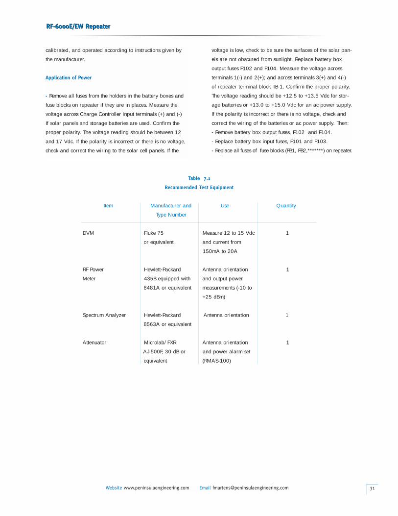
Application of Power
• Remove all fuses from the holders in the battery boxes and
fuse blocks on repeater if they are in places. Measure the
voltage across Charge Controller input terminals (+) and (-)
If solar panels and storage batteries are used. Confirm the
proper polarity. The voltage reading should be between 12
and 17 Vdc. If the polarity is incorrect or there is no voltage,
check and correct the wiring to the solar cell panels. If the
RF-6000E/EW RepeaterRF-6000E/EW Repeater
Website www.peninsulaengineering.com Email [email protected]
voltage is low, check to be sure the surfaces of the solar pan-
els are not obscured from sunlight. Replace battery box
output fuses F102 and F104. Measure the voltage across
terminals 1(-) and 2(+); and across terminals 3(+) and 4(-)
of repeater terminal block TB-1. Confirm the proper polarity.
The voltage reading should be +12.5 to +13.5 Vdc for stor-
age batteries or +13.0 to +15.0 Vdc for an ac power supply.
If the polarity is incorrect or there is no voltage, check and
correct the wiring of the batteries or ac power supply. Then:
- Remove battery box output fuses, F102 and F104.
- Replace battery box input fuses, F101 and F103.
- Replace all fuses of fuse blocks (FB1, FB2,*******) on repeater.
31
Table 7.1
Recommended Test Equipment
Item Manufacturer and Use Quantity
Type Number
DVM Fluke 75 Measure 12 to 15 Vdc 1
or equivalent and current from
150mA to 20A
RF Power Hewlett-Packard Antenna orientation 1
Meter 435B equipped with and output power
8481A or equivalent measurements (-10 to
+25 dBm)
Spectrum Analyzer Hewlett-Packard Antenna orientation 1
8563A or equivalent
Attenuator Microlab/FXR Antenna orientation 1
AJ-500F, 30 dB or and power alarm set
equivalent (RMAS-100)
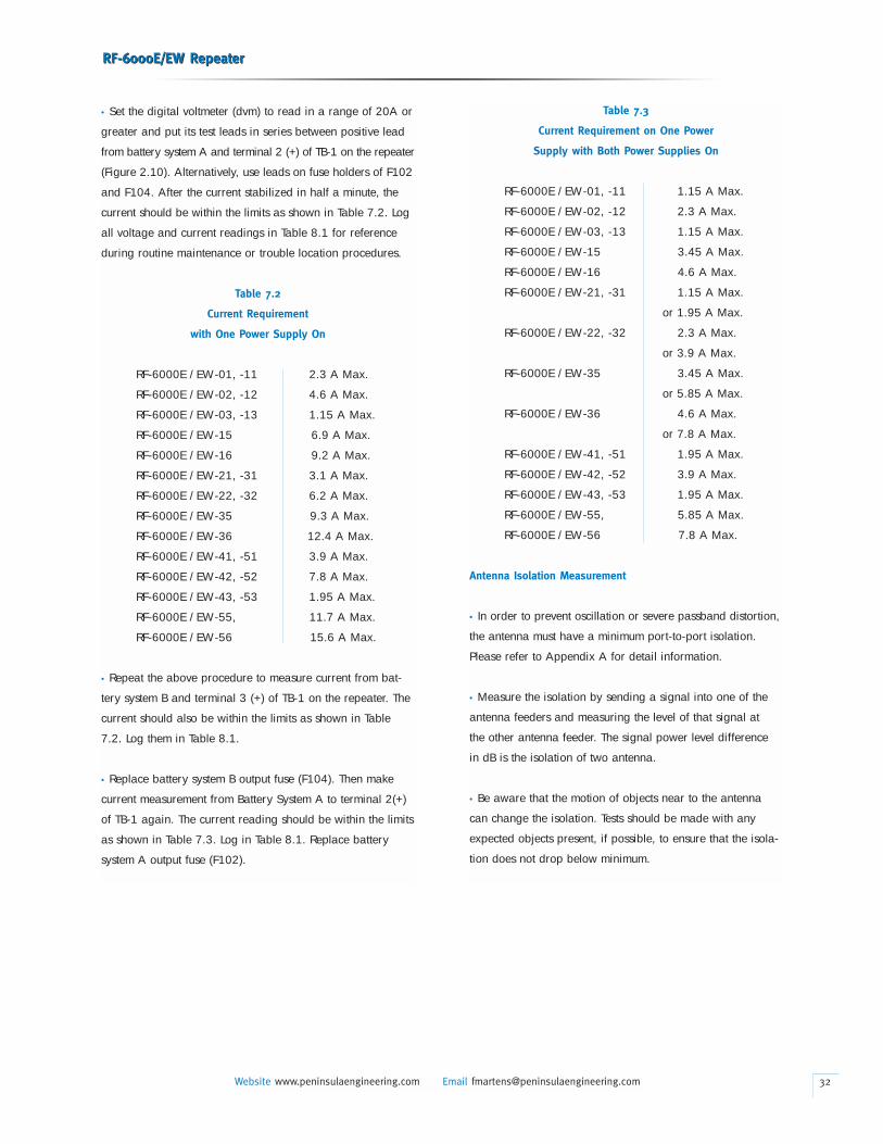
• Set the digital voltmeter (dvm) to read in a range of 20A or
greater and put its test leads in series between positive lead
from battery system A and terminal 2 (+) of TB-1 on the repeater
(Figure 2.10). Alternatively, use leads on fuse holders of F102
and F104. After the current stabilized in half a minute, the
current should be within the limits as shown in Table 7.2. Log
all voltage and current readings in Table 8.1 for reference
during routine maintenance or trouble location procedures.
Table 7.2
Current Requirement
with One Power Supply On
RF-6000E /EW-01, -11 2.3 A Max.
RF-6000E /EW-02, -12 4.6 A Max.
RF-6000E /EW-03, -13 1.15 A Max.
RF-6000E /EW-15 6.9 A Max.
RF-6000E /EW-16 9.2 A Max.
RF-6000E /EW-21, -31 3.1 A Max.
RF-6000E /EW-22, -32 6.2 A Max.
RF-6000E /EW-35 9.3 A Max.
RF-6000E /EW-36 12.4 A Max.
RF-6000E /EW-41, -51 3.9 A Max.
RF-6000E /EW-42, -52 7.8 A Max.
RF-6000E /EW-43, -53 1.95 A Max.
RF-6000E /EW-55, 11.7 A Max.
RF-6000E /EW-56 15.6 A Max.
• Repeat the above procedure to measure current from bat-
tery system B and terminal 3 (+) of TB-1 on the repeater. The
current should also be within the limits as shown in Table
7.2. Log them in Table 8.1.
• Replace battery system B output fuse (F104). Then make
current measurement from Battery System A to terminal 2(+)
of TB-1 again. The current reading should be within the limits
as shown in Table 7.3. Log in Table 8.1. Replace battery
system A output fuse (F102).
RF-6000E/EW RepeaterRF-6000E/EW Repeater
Website www.peninsulaengineering.com Email [email protected]
Table 7.3
Current Requirement on One Power
Supply with Both Power Supplies On
RF-6000E /EW-01, -11 1.15 A Max.
RF-6000E /EW-02, -12 2.3 A Max.
RF-6000E /EW-03, -13 1.15 A Max.
RF-6000E /EW-15 3.45 A Max.
RF-6000E /EW-16 4.6 A Max.
RF-6000E /EW-21, -31 1.15 A Max.
or 1.95 A Max.
RF-6000E /EW-22, -32 2.3 A Max.
or 3.9 A Max.
RF-6000E /EW-35 3.45 A Max.
or 5.85 A Max.
RF-6000E /EW-36 4.6 A Max.
or 7.8 A Max.
RF-6000E /EW-41, -51 1.95 A Max.
RF-6000E /EW-42, -52 3.9 A Max.
RF-6000E /EW-43, -53 1.95 A Max.
RF-6000E /EW-55, 5.85 A Max.
RF-6000E /EW-56 7.8 A Max.
Antenna Isolation Measurement
• In order to prevent oscillation or severe passband distortion,
the antenna must have a minimum port-to-port isolation.
Please refer to Appendix A for detail information.
• Measure the isolation by sending a signal into one of the
antenna feeders and measuring the level of that signal at
the other antenna feeder. The signal power level difference
in dB is the isolation of two antenna.
• Be aware that the motion of objects near to the antenna
can change the isolation. Tests should be made with any
expected objects present, if possible, to ensure that the isola-
tion does not drop below minimum.
32
• Repeat the test at several frequencies across the designated
bandwidth, making sure the minimum isolation is met at
ALL frequencies.
• If isolation is not met, try repositioning the antenna, or adding
intervening shielding and then measure again.
Antenna Orientation, AGC/ALC set and Output Measurement
• Before antenna orientation begins, the amplifiers must be
operating in their full gain mode (out of AGC/ALC range).
The setting of the AGC/ALC along with a high input level
(greater than [desired output power level in dBm-max. linear
gain in dB]) may cause the normal action of the AGC/ALC
circuit to mask changes in power due to azimuth and elevation
sweeping of the antennas. The output power of an amplifier
will increase in level as the input level is increased to the
point where the AGC/ALC has been set (eg. +18 dBm). Further
increases in input level will be absorbed in the AGC/ALC
circuit. Use the amplifier power monitor point as a signal
strength indicator. The input level can be reduced temporarily
by inserting a fixed or variable attenuator pad ahead of
the amplifier. The attenuation required will range from 0 to
20 dB depending on desired power and input signal level.
Remove the input semi-rigid coax cable and place the attenu-
ator in series with the coax or use flexible coax as required
for fit. Reduce the input level until the output power drops
below the desired power level. If during antenna orientation,
the power rises to the desired power level, reduce the input
level again and then continue with antenna orientation.
NOTE: For those amplifiers equipped with field-adjustable
gain, their maximum gain can be reduced such that the
system is out of AGC/ALC for antenna alignment. Be sure to
return the potentiometers to their normal positions after
antenna are aligned.
• Connect the power meter or spectrum analyzer to the f1
amplifier, A1, RF PWR MON port. With a signal transmitted
from the A terminal, position the antenna A for a maximum
power reading on the meter or analyzer. After antenna A is
aligned, remove any temporarily installed input attenuators.
Reset the power level with the AGC/ALC adjustment if need-
ed. The AGC/ALC adjustment is located near the output end
of each amplifier, see Fig.2.9. Use screw driver to adjust the
RF-6000E/EW RepeaterRF-6000E/EW Repeater
Website www.peninsulaengineering.com Email [email protected]
AGC/ALC potentiometer CW to reduce the power setting or
CCW to increase the AGC/ALC set point. Log the power
reading to fulfill FCC requirements. Remove the meter from
the f1 Amplifier PWR MON to the f2 Amplifier PWR MON.
With a signal transmitted from the B terminal, position the
antenna B for a maximum power reading on the meter or
analyzer. After antenna B is aligned, remove any temporarily
installed input attenuators. Set the power level with the
AGC/ALC adjustment if needed. Log the power reading to
fulfill FCC requirements. Measure and log the power at
any additional amplifier directional couplers so equipped (f3,
f4...). Remove the meter.
• After the antenna orientation has been completed at both
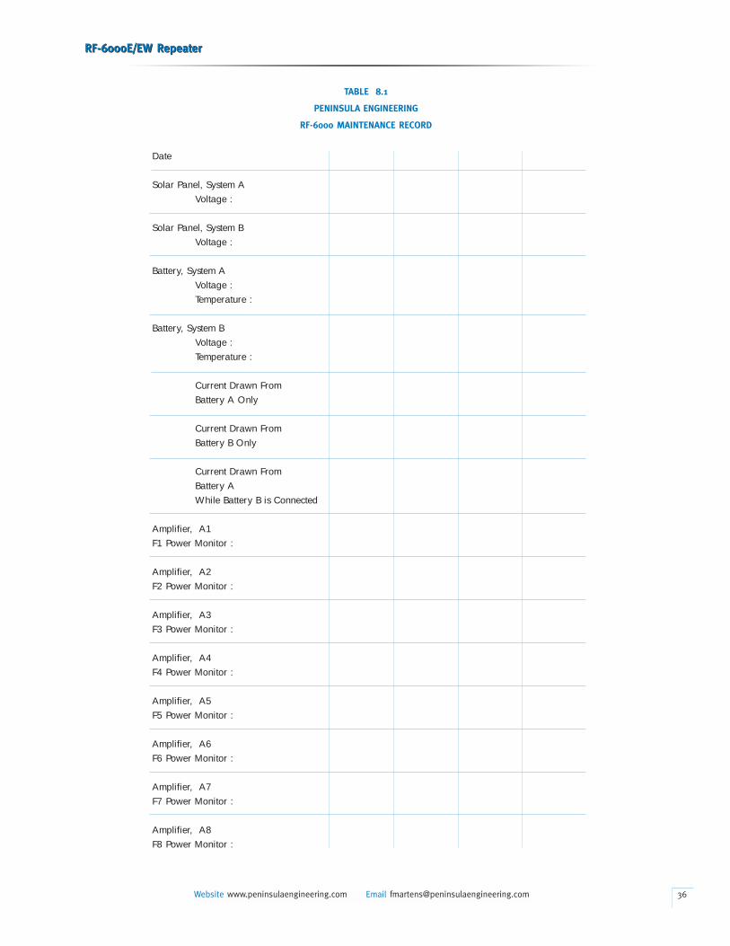
terminals and the repeater, AGC readings should be taken at
the end terminals and logged for reference. A maintenance
test record is shown in Table 8.1.
RX/TX Pad Installation
• If required in the field, the RX/TX pads should be installed
at the RF input or output of amplifiers. To install it, turn off
the DC power supply first. Disconnect the input/output semi-
rigid cable from the amplifier. Connect the SMA male end
of the pad to the amplifier SMA female input/output; and
then connect input/output cable to the other end of the pad.
Check all coaxial connections for tightness (8 in-lbs). Set
output power level by adjusting AGC/ALC.
8. MAINTENANCE
Routine Maintenance
• Unless unique conditions require more frequent maintenance,
routine maintenance should be performed annually. Clean
the surfaces of the solar cell panels with isopropyl alcohol or
a mild detergent solution. Do not use alcohol compounds
containing acetone. Check and clean the wiring connections
to the solar charge controllers and the battery connectors as
necessary. Follow the procedures as stated in Sections 7.03
through 7.06, measure the current of the repeater system.
The current reading should be within the same limits. Also
measure the power level at PWR MON of each amplifier with
a power meter. Log current and power reading in Table 8.1.
33
Administration Requirements
• The Local Telecommunications Administrations may require
measurement of the output power of the repeater at installation
or when any changes are made which cause the output
power to change. Using the power meter, measure and log
the output power in Table 7.2 as indicated in paragraph 7.05.
Trouble Location
• Soft failure of one amplifier will be indicated by a drop of
approximately 6 dB in the received signal level at the terminal
in the direction of transmission, which will be indicated on
the agc meter on the terminal equipment. Amplifier AGC/ALC
may correct for this drop. The failure of one amplifier will most
likely be caused by a failure of DC power to the amplifier.
Using the dvm, check for presence of dc voltage at the amplifier
power feed through connections. Another way to check is
insert dvm probes to pins #1 and #2 (or #3) from the back side
of amplifier wire harness as shown in Figure 2.9.
• If the received signal at the terminals is low but does not indi-
cate a complete failure on one amplifier, the most likely cause is
low voltage from the batteries. Low voltage is an indication of
a possible battery failure, or a failure of the charging system. In
the case of the primary cell batteries, the batteries are probably
reaching the limit of their life. Check the batteries and all power
lead connections. If solar panels are used, be sure they are not
obstructed from sunlight and that the surfaces are clean. If an
ac power supply is used, low voltage is probably the result of
a power failure, the duration of which exceeded the reserve
power limits of the standby battery. Check the standby battery
in accordance with the instructions given by the manufacturer
of the power supply.
Amplifier Replacement, Out of Service
• When an amplifier must be replaced in an Out of Service
condition, do the following:
a) Unplug amplifier’s power connector.
b) Disconnect input and output SMA cables.
c) Disconnect BNC cable from DC monitor point.
d) Remove mounting hardware (6 screws).
e) Remove amplifier.
• To install the replacement amplifier:
RF-6000E/EW RepeaterRF-6000E/EW Repeater
Website www.peninsulaengineering.com Email [email protected]
a) Mount the amplifier on the panel securing with
mounting hardware.
b) Connect the BNC cable to DC monitor point.
c) Connect input and output SMA cables.
d) Check all coax connections for tightness (8in/lbs)
e) Plug-in the amplifier’s power connector.
f) Verify operation by measuring power at SMA
power monitor.
g) Set output power by adjusting AGC/ALC.
Amplifier Replacement, In Service
(For Duplex and One-Way Options Only)
• When an amplifier must be replaced while the repeater is
in service (eg. soft failure), do the following:
a) Mount a temporary spare amplifier in and oriented
in the same input/output direction as the amplifier
to be replaced.
b) Remove the SMA terminations from the coaxial
circulators in series, identified by F1 or F2, with the
amplifier to be replaced (shown in Figures 1.1 and 1.2).
c) Connect the flexible coaxial cables or semi-rigid
coaxial cables (part of the sparing kit) from the
input(RX) coax circulator open port to the temporary
spare amplifier’s input SMA. Likewise connect the
output(TX) coax circulator open port to the temporary
spare amplifier’s output SMA connector.
d) Connect the DC leads from the temporary spare
amplifier using the power adapter in the sparing kit
to the “A” battery if replacing amplifier A1, or “B”
if replacing amplifier A2.
e) Disconnect the input coaxial cable from the amplifier
to be replaced. The signal is now carried in the
temporary spare amplifier, but may be 20 dB down.
f) Unplug the power connector of the amplifier to
be replaced.
g) Disconnect the output coaxial cable from the amplifier
to be replaced.
h) Re-set the output power of the temporary spare
amplifier by adjusting its AGC/ALC.
i) Remove BNC cable from DC monitor point of the
replaced amplifier to the temporary spare.
j) Unscrew mounting hardware (6ea) and remove the
defective amplifier.
34
• To install a replacement amplifier in service:
a) Mount the amplifier on the panel securing with
mounting screws.
b) Connect BNC cable to DC monitor point.
c) Connect the output coaxial cable to the replacement
amplifier’s output. Signal level will drop 20 dB.
d) Plug in the amplifier’s power connector.
e) Connect the input coaxial cable to the replacement
amplifier’s input. Signal level should be close to
normal. Set power by adjusting AGC/ALC.
f) Remove the power connections from the temporary
spare amplifier.
g) Disconnect the flexible or semi-rigid coax cables
from the coax circulators and from the temporary
spare amplifier.
h) Replace the SMA terminations on the coax circulators.
Check the output power of the amplifier. Re-set its
power by adjusting AGC/ALC if needed.
i) Remove the temporary spare amplifier.
RF-6000E/EW RepeaterRF-6000E/EW Repeater
Website www.peninsulaengineering.com Email [email protected]
CAUTION
Due to unpredictable reflections within the RF-6000E, EW,
operation with a temporary spare amplifier, it may be degrad-
ed somewhat from normal, particularly in high capacity
digital and analog systems. Be sure the AGC/ALC is set
for the correct power level in your system.
Return Procedure
• Once it is determined that a unit is faulty, contact the Peninsula
Engineering Repair Department at: 1-925-901-0103. A rep-
resentative will issue a Return Authorization Number (RMA)
and shipping instructions.
• Reship the units in containers similar to those (if not the
same) in which the units were originally delivered in order to
minimize the potential for shipping damage. Insure that the
packing material adequately isolates the units from undue
contact with the shipping container.
35
RF-6000E/EW RepeaterRF-6000E/EW Repeater
Website www.peninsulaengineering.com Email [email protected] 36
TABLE 8.1
PENINSULA ENGINEERING
RF-6000 MAINTENANCE RECORD
Date
Solar Panel, System AVoltage :
Solar Panel, System BVoltage :
Battery, System AVoltage :Temperature :
Battery, System BVoltage :Temperature :
Current Drawn FromBattery A Only
Current Drawn FromBattery B Only
Current Drawn FromBattery A While Battery B is Connected
Amplifier, A1F1 Power Monitor :
Amplifier, A2F2 Power Monitor :
Amplifier, A3F3 Power Monitor :
Amplifier, A4F4 Power Monitor :
Amplifier, A5F5 Power Monitor :
Amplifier, A6F6 Power Monitor :
Amplifier, A7F7 Power Monitor :
Amplifier, A8F8 Power Monitor :
APPENDIX A
Antenna System
The antenna system is vital to the success of any RF
repeater. It was only when high performance microwave
antennas became available that high capacity RF repeater
became practical. The antennas must have high gain (25-50
dB), clean pattern, low sidelobes and good Front-to-Back
ratio. It is the sidelobes and Front-to-Back ratio that control
much of the echo that results from antenna to antenna
coupling. Foreground obstructions also produce an echo
component which is site specific.
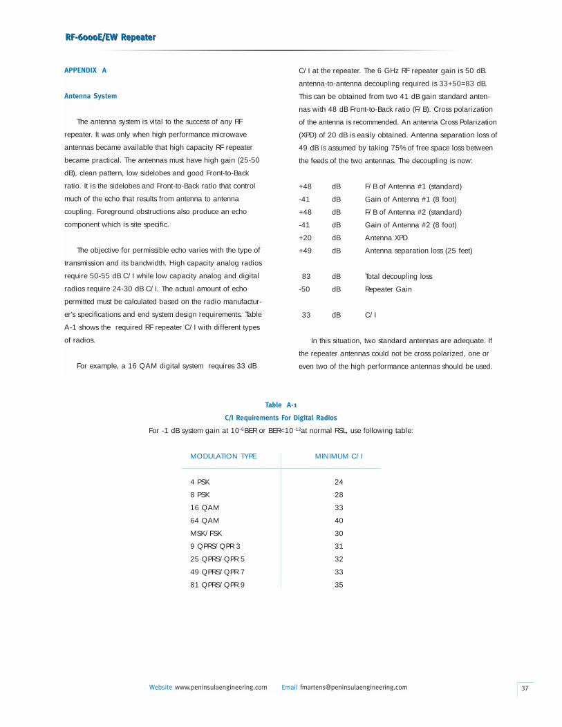
The objective for permissible echo varies with the type of
transmission and its bandwidth. High capacity analog radios
require 50-55 dB C/I while low capacity analog and digital
radios require 24-30 dB C/I. The actual amount of echo
permitted must be calculated based on the radio manufactur-
er’s specifications and end system design requirements. Table
A-1 shows the required RF repeater C/I with different types
of radios.
For example, a 16 QAM digital system requires 33 dB
RF-6000E/EW RepeaterRF-6000E/EW Repeater
Website www.peninsulaengineering.com Email [email protected]
C/I at the repeater. The 6 GHz RF repeater gain is 50 dB.
antenna-to-antenna decoupling required is 33+50=83 dB.
This can be obtained from two 41 dB gain standard anten-
nas with 48 dB Front-to-Back ratio (F/B). Cross polarization
of the antenna is recommended. An antenna Cross Polarization
(XPD) of 20 dB is easily obtained. Antenna separation loss of
49 dB is assumed by taking 75% of free space loss between
the feeds of the two antennas. The decoupling is now:
+48 dB F/B of Antenna #1 (standard)
-41 dB Gain of Antenna #1 (8 foot)
+48 dB F/B of Antenna #2 (standard)
-41 dB Gain of Antenna #2 (8 foot)
+20 dB Antenna XPD
+49 dB Antenna separation loss (25 feet)
83 dB Total decoupling loss
-50 dB Repeater Gain
33 dB C/I
In this situation, two standard antennas are adequate. If
the repeater antennas could not be cross polarized, one or
even two of the high performance antennas should be used.
37
Table A-1
C/I Requirements For Digital Radios
For -1 dB system gain at 10 BER or BER<10 at normal RSL, use following table:
MODULATION TYPE MINIMUM C/I
4 PSK 24
8 PSK 28
16 QAM 33
64 QAM 40
MSK/FSK 30
9 QPRS/QPR 3 31
25 QPRS/QPR 5 32
49 QPRS/QPR 7 33
81 QPRS/QPR 9 35
-6 -12
RF-6000E/EW RepeaterRF-6000E/EW Repeater
Website www.peninsulaengineering.com Email [email protected] 38
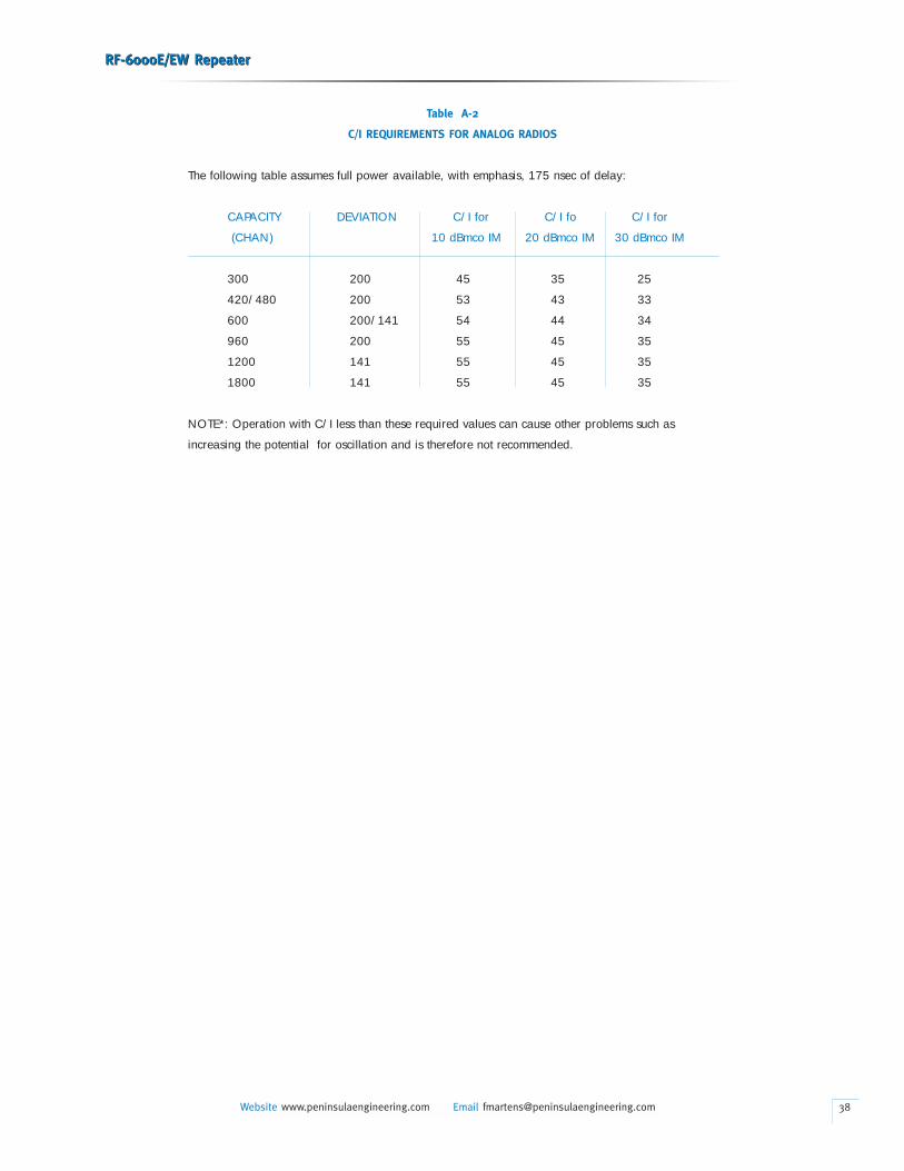
Table A-2
C/I REQUIREMENTS FOR ANALOG RADIOS
The following table assumes full power available, with emphasis, 175 nsec of delay:
CAPACITY DEVIATION C/I for C/I fo C/I for
(CHAN) 10 dBmco IM 20 dBmco IM 30 dBmco IM
300 200 45 35 25
420/480 200 53 43 33
600 200/141 54 44 34
960 200 55 45 35
1200 141 55 45 35
1800 141 55 45 35
NOTE*: Operation with C/I less than these required values can cause other problems such as
increasing the potential for oscillation and is therefore not recommended.
Recommended