
HU
MID
ITY
RELAYS & CONTACTORSR
EL
AY
S &
C
ON
TAC
TO
RS
LY/MK Series | p. 1125 RV8H Series | p. 1132 G7L Series | p. 1150
Hundreds of Options in Stock, and Thousands of Options Available.

MODEL/SERIES PAGEProducts manufactured in the United States
Products that are new to the catalog
ke le .com
RELAYS & CONTACTORS
RIB Series | p. 1133
RV8H | p. 1132
DPC Series | p. 1151
RE
LA
YS
&
CO
NT
AC
TO
RS
Board Mounted RelaysMR Series — Air Products and Controls Multi-Voltage Control Relays . . . . .1143RIB M Series — Functional Devices Modular Panel Relays . . . . . . . . . . . . . .1145 ContactorsDPC Series — Definite Purpose Contactors . . . . . . . . . . . . . . . . . . . . . . . . .1151T30, T40, T60, T90 — EEC Definite Purpose Contactors . . . . . . . . . . . . . . . .1152 Enclosed RelaysRIB, RIBT Pilot Series — Relay In A Box for Pump Level Switch Control . . .1133RIB, RIBT Power Series — Functional Devices Relay In A Box . . . . . . . . . .1135RIB01 and RIB02 Series — Functional Devices Relay in a Box Dry C
ontact Input Series . . . . . . . . . . . . . . . . . . . . . . . . . . . . . . . . . . . . . . . . . .1138PAM-1, PAM-4 — Air Products and Controls Multi-Voltage Relay Modules . .1147 Plug-In General Purpose RelaysRH, RJ, RR Series — IDEC General-Purpose Relays . . . . . . . . . . . . . . . . . .1121SH, SJ, SR Series — IDEC Relay Sockets . . . . . . . . . . . . . . . . . . . . . . . . . .1123G2R-S, LY, MK Series — Omron General-Purpose Relays . . . . . . . . . . . . . .1125P2RF, PF, PTF Series — Omron Relay Sockets . . . . . . . . . . . . . . . . . . . . . .1127781, 782, 783, 784 Series — Magnecraft Relays . . . . . . . . . . . . . . . . . . . . . .112970-781D5-1, 70-782D-1, 70-783D-1, 70-784D-1 — Magnecraft Relay
Sockets . . . . . . . . . . . . . . . . . . . . . . . . . . . . . . . . . . . . . . . . . . . . . . . . . . .1131RV8H Series — 6mm Interface Relays . . . . . . . . . . . . . . . . . . . . . . . . . . . . . .113220307 Series — Special Voltage Relays . . . . . . . . . . . . . . . . . . . . . . . . . . . . .1155 Power RelaysKE375, KE900 Series — Power Relays . . . . . . . . . . . . . . . . . . . . . . . . . . . . .1148G7L Series — Omron Power Relays . . . . . . . . . . . . . . . . . . . . . . . . . . . . . . .1150 Specialty Relay ProductsRIBL Latching Series — Relay In A Box Latching Relay Series . . . . . . . . . .1137RIBTW Series — Functional Devices LonWorks Relay in a Box . . . . . . . . . .1139RIBTW2401B-BC — Functional Devices BACnet Relay in a Box . . . . . . . . . .1140RIBW Series — Functional Devices Wireless Control Relays . . . . . . . . . . . .1141RSSDN — IDEC Solid State Relay . . . . . . . . . . . . . . . . . . . . . . . . . . . . . . . . .1153Model ALT — Alternating Relay . . . . . . . . . . . . . . . . . . . . . . . . . . . . . . . . . . .1155PIL-2 — Kele Motor Starter Interface . . . . . . . . . . . . . . . . . . . . . . . . . . . . . . .1167 Timing RelaysRTE Series — IDEC Multifunction Electronic Timers . . . . . . . . . . . . . . . . . . .1158TRU Series — Multifunction Timing Relays . . . . . . . . . . . . . . . . . . . . . . . . . .1160821TD10H, TDRSOXP, TDRSRXP — Magnecraft Time Delay Relays . . . . .1162438USA, 438USA-INT — Delay On Make / Interval Timers . . . . . . . . . . . . . .1156TMV8000, KRDM — Delay-on-Make Timing Relays . . . . . . . . . . . . . . . . . . . .1164TA, CT Series — Lockout Delay Timer . . . . . . . . . . . . . . . . . . . . . . . . . . . . . .1165KRDB, KSDB, TDUB — Delay-on-Break Timing Relays . . . . . . . . . . . . . . . .1166

NEW!
1121
RELAYS & CONTACTORSRELAYS & CO
NTACTORS
19
WE MAKE IT EASY. kele.com 888-397-5353 USAMarch 2014
RH SERIES
RR Series
RH SERIES (UL ratings)
RR SERIES (UL ratings)
RATEDVOLTAGE
RATED CURRENT (mA) ±15% @ 20°C60 Hz 50 Hz
COIL RESISTANCE (Ω)±10% @ 20°C
AC
DC
1224
120240
1224
4PDT21.284.57,3609,1204PDT
96
388
3PDT25.3103
10,80012,1003PDT100
400
DPDT39.3153––
DPDT160
650
SPDT16583
16.58.3
SPDT188
750
4PDT19698
19.59.8
3PDT16581
16.48.2
DPDT12160.5
––
SPDT86428.64.9
4PDT16583
16.58.3
3PDT14070
14.27.1
DPDT10050––
SPDT75377.54.3
SPDT6432
DPDT75
36.9
3PDT12060
4PDT12562
VOLTAGERESISTIVE GENERAL USE HORSEPOWER RATING
RH31/3 hp1/6 hp
––
1/3 hp1/6 hp
––
––––
RH1RH2RH4
5A7.5A
––
RH36.5A7.5A
––
RH4RH1RH27A–7A–
RH47.5A10A–
10A
RH37.5A10A10A–
RH1RH210A–
10A–
240V AC120V AC30V DC28V DC
RATEDVOLTAGE
Rated Current (mA) ±15% @ 20°C60 Hz 50 Hz
AC
DC
1224
1202401224
3651823518––
21010520.510.5
24512124
12.112060
VOLTAGE RESITIVE (A) INDUCTIVE (A)cos = 0.3
MOTOR LOAD (hp)
77.57
1/31/4–
101010
240 AC120 AC30 DC
RJ Series Rated Current (mA) ±15% @ 20°C
60 HzWITHOUT LED1 WITH LED1
50 Hz 60 Hz 50 Hz
ACBLADE & PCB
BLADEPCBDC
24V120V
24V24V
2436,4001,0801,080
37.57.5
43.98.8
41.17.4
47.58.7
Maximum continuous applied voltage RH, RR 110% of rated voltage RJ 140% of rated voltagePull-in voltage RH, RR, RJ/AC 80% of rated voltage RJ, RJ/DC 70% of rated voltageDrop-out voltage AC 30% or more of rated voltage DC 10% or more of rated voltageContact material RH Silver cadmium oxide RR Silver RJ Silver nickel alloy
Contact resistance RH 50 mΩ maximum RR 30 mΩ maximum RJ 50 mΩ maximumOperate time RH, RR 25 ms maximum RJ 15 ms maximumRelease time RH, RR 25 ms maximum RJ 10 ms maximumMin load RH 24 VDC/30 mA, 5 VDC/100 mA RR 24 VDC/10 mA, 5 VDC/20 mA RJ 5 VDC/100 mAOperating temp -22° to 158°F (-30° to 70°C)Agency approvals UL-recognized component, (RH, RR): File #E66043, (RJ): File #E55996 CSA certified, File #LR35144; CE certified (not RR blade style)Warranty 1 year
COIL RATINGS CONTACT RATINGS
RJ1S RJ2S
12A @ 250 VAC/30 VDC12A @ 250 VAC; 6A @ 30 VDC7.5A @ 250 VAC; 6A @ 30 VDC7.5A @ 250 VAC; 3A @ 30 VDC
N.O.N.C.N.O.N.C.
Resistive Load(Maximum)
CONTACT
8A @ 250 VAC/30 VDC8A @ 250 VAC; 4A @ 30 VDC4A @ 250 VAC; 4A @ 30 VDC4A @ 250 VAC; 2A @ 30 VDC
Inductive Load(Maximum)
RJ Series (UL ratings)
COIL RESISTANCE (Ω)±10% @ 20°C
COIL RESISTANCE (Ω)±10% @ 20°C
MODELS
22.122.1
25.7–
1. LED indicator is only available on Blade relays.
IDEC GENERAL-PURPOSE RELAYSRH, RJ, RR SERIES
DESCRIPTIONIDEC general-purpose relays are available in the RH Series blade-style relays and the RR Series pin-style relays and the RJ Series compact relays .
The RH Series features a 10A switching capacity . They are available in SPDT, DPDT, 3PDT, and 4PDT contact configurations, driven by AC or DC coils, and they have blade terminals for socket mounting .
The RR Series has a 10A contact rating . The RR Series relays are available in SPDT, DPDT, and 3PDT configurations driven by AC or DC coils, and they have pin or blade terminals for socket mounting .
The RJ Series is compact to reduce space requirements . They are available in a 12A SPDT version and an 8A DPDT version . They are driven by AC or DC coils and have blade terminals for socket mounting .
FEATURES• Blade style, pin style, and compact models• Indicator light and/or check button available • Surface or DIN rail mount• UL recognized, CSA certified
SPECIFICATIONS
RJ Series RH Series RR Series

NEW!RELAYS & CONTACTORS
1122
NEW!RE
LAYS
& C
ONT
ACTO
RS
19
WHEN YOU NEED IT RIGHT, RIGHT NOW, CALL KELE.kele.com888-397-5353 USA March 2014
IDEC GENERAL-PURPOSE RELAYSRH, RJ, RR SERIES
1 .39 (3 .56) or less
in(cm)
2 .19 (5 .55)
0 .55 (1 .39) 0 .82 (2 .1)
1 .07
(2 .
75)
1 .07
(2 .
75)
1 .07
(2 .
75)
1 .22 (3 .1)
1 .14 (2 .9) 1 .42 (3 .6) 1 .87 (4 .8) or less 1 .42 (3 .64)
0 .2 (0 .5)
1 .42(3 .64)
1 .41
8 (3
.6)
1 .41
8 (3
.6)
RR2P RR1BA, RR2BA, RR3B
RR Series Power Relays (blade)
RH Series Relays (blade)
RR3PA
RH2B RH3BRH1B
1 .07
(2 .
75)
1 .60 (4 .1)
RH4B
RR Series Relays (pin)
2
4
3
1 5
1 .06 (2 .7) 0 .5 (1 .27)
1 .13
(2 .
38)
RJ Series Relays (blade)
3
4 5
6
72
1 8
(+)(-)
RR2P
3 9
8
76
5
4
2 10
1 11(+)(-)
RR3PA
7
A B
5
2
(-) (+)
RR1BA
BA
7
4
1
9
6
3
(+)(-)RR2BA
8
5
2
7
4
1
9
6
3
BA
(+)(-)RR3B
9
5
1
13 14(-) (+)
RH1B
13 (-) 14(+)
RH3B
9
5
1
10
6
2
12
8
4
13 (-) 14(+)
RH4B
9
5
1
11
7
3
12
8
4
10
6
2
9
5
1
12
8
4
13 14(-) (+)
RH2B
1 5 1 8
3
4
2
4
3
2
5
6
7
RJ1S RJ2S
WIRING
DIMENSIONS
ORDERING INFORMATION
RH1B U AC24V
Example: RR2PUAC24V DPDT relay 8 pin with 24VAC coil
U Standard relayUL Indicator lightULC Indicator light and check button
AC12V 12 VAC coil voltageAC24V 24 VAC coil voltageAC120V 120 VAC coil voltageAC240V 240 VAC coil voltageDC12V 12 VDC coil voltageDC24V 24 VDC coil voltage
MODEL DESCRIPTIONRH1B Relay, SPDT, blade (use SH1B-05 socket)RH2B Relay, DPDT, blade (use SH2B-05 socket)RH3B Relay, 3PDT, blade (use SH3B-05 socket)RH4B Relay, 4PDT, blade (use SH4B-05 socket)
RJ1S C A24
C No optionsCL LED indicator
A24 24 VAC coil voltageA120 120 VAC coil voltageD24 24 VDC coil voltage
MODEL DESCRIPTIONRJ1S Relay, SPDT (use SJ1S-05B socket)RJ2S Relay, DPDT (use SJ2S-05B socket)
RR2P U AC24V
U Standard relayUL Indicator lightULC Indicator light and check button
AC12V 12 VAC coil voltageAC24V 24 VAC coil voltageAC120V 120 VAC coil voltageAC240V 240 VAC coil voltageDC12V 12 VDC coil voltageDC24V 24 VDC coil voltage
MODEL DESCRIPTIONRR2P Relay, DPDT, 8 pin (use SR2P-05 or SR2P-06)RR3PA Relay, 3PDT, 11 pin (use SR3P-06 socket)RR1BA Relay, SPDT, 11 blade (use SR3B-05 socket)RR2BA Relay, DPDT, 11 blade (use SR3B-05 socket)RR3B Relay, 3PDT, 11 blade (use SR3B-05 socket)
LegendNCNO
Bottom View
RELATED PRODUCTS PAGEDIN-3F 35 mm DIN rail, steel, 39.4" (1m), RoHS compliant 860DIN-3F, BAM-1000 DIN rail 860SH, SR, SJ Series Relay sockets 1123
NEW!
1123
RELAYS & CONTACTORSRELAYS & CO
NTACTORS
19
WE MAKE IT EASY. kele.com 888-397-5353 USAMarch 2014
Model Socket Type Rated Voltage
Rated Current
Hold Down Clip orSpringWire Size Wire Size Weight Approvals
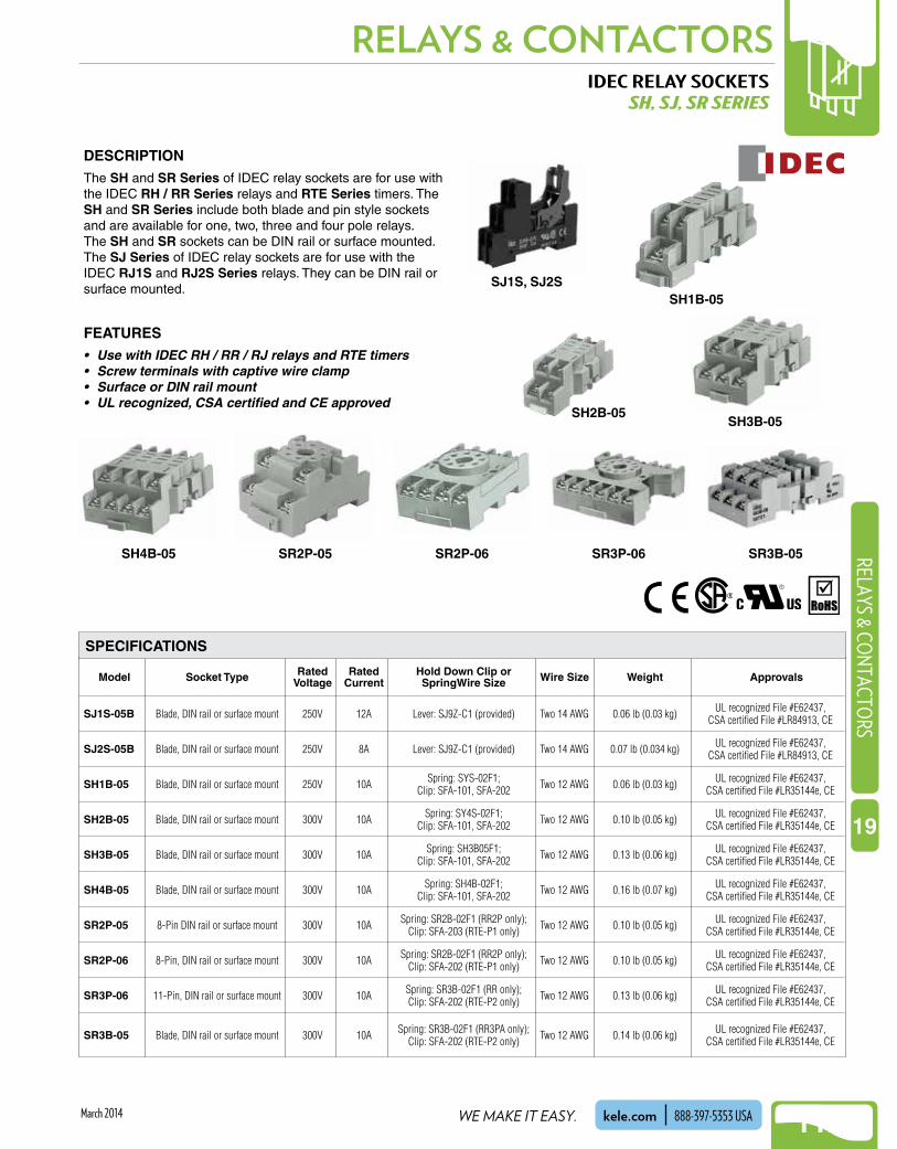
SJ1S-05B Blade, DIN rail or surface mount 250V 12A Lever: SJ9Z-C1 (provided) Two 14 AWG 0.06 lb (0.03 kg) UL recognized File #E62437, CSA certified File #LR84913, CE
SJ2S-05B Blade, DIN rail or surface mount 250V 8A Lever: SJ9Z-C1 (provided) Two 14 AWG 0.07 lb (0.034 kg) UL recognized File #E62437, CSA certified File #LR84913, CE
SH1B-05 Blade, DIN rail or surface mount 250V 10A Spring: SYS-02F1; Clip: SFA-101, SFA-202 Two 12 AWG 0.06 lb (0.03 kg) UL recognized File #E62437,
CSA certified File #LR35144e, CE
SH2B-05 Blade, DIN rail or surface mount 300V 10A Spring: SY4S-02F1; Clip: SFA-101, SFA-202 Two 12 AWG 0.10 lb (0.05 kg) UL recognized File #E62437,
CSA certified File #LR35144e, CE
SH3B-05 Blade, DIN rail or surface mount 300V 10A Spring: SH3B05F1; Clip: SFA-101, SFA-202 Two 12 AWG 0.13 lb (0.06 kg) UL recognized File #E62437,
CSA certified File #LR35144e, CE
SH4B-05 Blade, DIN rail or surface mount 300V 10A Spring: SH4B-02F1; Clip: SFA-101, SFA-202 Two 12 AWG 0.16 lb (0.07 kg) UL recognized File #E62437,
CSA certified File #LR35144e, CE
SR2P-05 8-Pin DIN rail or surface mount 300V 10A Spring: SR2B-02F1 (RR2P only); Clip: SFA-203 (RTE-P1 only) Two 12 AWG 0.10 lb (0.05 kg) UL recognized File #E62437,
CSA certified File #LR35144e, CE
SR2P-06 8-Pin, DIN rail or surface mount 300V 10A Spring: SR2B-02F1 (RR2P only); Clip: SFA-202 (RTE-P1 only) Two 12 AWG 0.10 lb (0.05 kg) UL recognized File #E62437,
CSA certified File #LR35144e, CE
SR3P-06 11-Pin, DIN rail or surface mount 300V 10A Spring: SR3B-02F1 (RR only); Clip: SFA-202 (RTE-P2 only) Two 12 AWG 0.13 lb (0.06 kg) UL recognized File #E62437,
CSA certified File #LR35144e, CE
SR3B-05 Blade, DIN rail or surface mount 300V 10A Spring: SR3B-02F1 (RR3PA only); Clip: SFA-202 (RTE-P2 only) Two 12 AWG 0.14 lb (0.06 kg) UL recognized File #E62437,
CSA certified File #LR35144e, CE
IDEC RELAY SOCKETSSH, SJ, SR SERIES
DESCRIPTIONThe SH and SR Series of IDEC relay sockets are for use with the IDEC RH / RR Series relays and RTE Series timers . The SH and SR Series include both blade and pin style sockets and are available for one, two, three and four pole relays . The SH and SR sockets can be DIN rail or surface mounted .The SJ Series of IDEC relay sockets are for use with the IDEC RJ1S and RJ2S Series relays . They can be DIN rail or surface mounted .
FEATURES• Use with IDEC RH / RR / RJ relays and RTE timers• Screw terminals with captive wire clamp• Surface or DIN rail mount• UL recognized, CSA certified and CE approved
SJ1S, SJ2SSH1B-05
SH2B-05SH3B-05
SH4B-05 SR2P-05 SR2P-06 SR3P-06 SR3B-05
SPECIFICATIONS

NEW!RELAYS & CONTACTORS
1124
NEW!RE
LAYS
& C
ONT
ACTO
RS
19
WHEN YOU NEED IT RIGHT, RIGHT NOW, CALL KELE.kele.com888-397-5353 USA March 2014
ORDERING INFORMATION
IDEC RELAY SOCKETSSH, SJ, SR SERIES
MODEL DESCRIPTIONSH1B-05 Relay socket, SPDT blade type, DIN/surface mountSH2B-05 Relay socket, DPDT blade type, DIN/surface mountSH3B-05 Relay socket, 3PDT blade type, DIN/surface mountSH4B-05 Relay socket, 4PDT blade type, DIN/surface mountSJ1S-05B Relay socket, SPDT blade type, DIN/surface mountSJ2S-05B Relay socket, DPDT blade type, DIN/surface mountSR2P-05 Relay socket, DPDT pin type, DIN/surface mountSR2P-06 Relay socket, DPDT pin type, DIN/surface mountSR3B-05 Relay socket, three-pole blade type, DIN/surface mountSR3P-06 Relay socket, 3PDT pin type, DIN/surface mount
DIMENSIONS
1
5
14 13
9
0.32(0.8)
0.66(1.7)
0.63(1.6)
0.63(1.6)
0.78(2.0)
0.10(0.25)
0.57(1.5)
0.98(2.5)
1.12(2.85)
in(cm)
2.62(6.7)
1.83(4.8)
0.16dia.
(0.42) 0 .14 dia .(0 .36)
2 MountingHoles
0.16 dia(0.42)
0 .31(0 .79)DIN
Rail
0 .17(0 .44)
0 .22(0 .55)
SH1B-05
1
5
14 13
12
8
9
0.32(0.8)
0.86(2.2)
1.03(2.6)
1.03(2.6)1.17
(3.0)
0.57(1.5)
0.98(2.5)
0.7(1.88)
1.12(2.85)
2.62(6.7)
1.83(4.8)
0.16dia.
(0.42)
2 MountingHoles
0.16 dia(0.42)
DINRail
0 .14 dia .(0 .36)
0 .31(0 .79)
0 .17(0 .44)
0 .22 (0 .55)
0.10(0.25)
4
SH2B-05
1
5
14 13
12
8
9
0.32(0.8)
1.25(3.2)
1.42(3.6)
1.42(3.6)
1.56(4.0)
0.57(1.5)
0.98(2.5)
0.7(1.88)
1.12(2.85)
2.62(6.7)
1.83(4.8)
0.16dia.
(0.42)
2 MountingHoles
0.16 dia(0.42)
DINRail
0 .14 dia .(0 .36)
0 .31(0 .79)
0 .17(0 .44)
0 .22(0 .55)
0.10(0.25)
4
10
6
2
SH3B-05
153
4
2
SJ1SSJ1S,SJ2S
632
1
7
SJ2S
4 5
8
0.6(1.6) 0.2 (0.4)
0.1(0.2)
1.2 (2.9)
2.8(7.1)
1.4 (3.5)1.9 (4.9)
2.2 (5.6)
SJ1S, SJ2S
1
5
14 13
12
8
9
0.32(0.8)
1.65(4.2)
1.81(4.6)
1.81(4.6)
1.97(5.0)
0.57(1.5)
0.98(2.5)
0.7(1.88)
1.12(2.85)
2.62(6.7)
1.83(4.8)
0.16dia.
(0.42)
2 Mounting Holes0.16 dia (0.42)
DINRail
0.14 dia.(0.36)
0.31(0.79)
0.17(0.44)
0.22(0.55)
0.10(.25)
4
10
6
2
7
3
11
SH4B-05
0.32(0.8)
in(cm)
1.40(3.6)
1.14(2.9)
1.14(2.9)
0.64(1.7)
0.78(2.0)
1.12(2.85)
1.25(2.85)
2.03(5.2)
1.28(3.3)
0.9(2.5)
0.16dia.
(0.42)
2 Mounting Holes0.16 dia. (0.42)
DINRail
0.14 dia.(0.36)
0.31(0.79)
0.17(0.44)
0.20(0.55)
0.12(0.25)
5 4
3
2
1
6
7
8
SR2P-05
0.32(0.8)
1.56(4.0)
1.3(3.3)
1.3(3.3)
0.7(1.8)
0.86(2.2)
1.0(2.55)
2.34(6.0)
0.97(2.5)
0.16dia.
(0.42)
DINRail
0.14 dia.(0.36)
0.31(0.79)
0.17(0.44)
0.20(0.55)
0.04(0.25)
5 4 3
21
6
7 8
2 Mounting Holes0.16 dia. (0.42)
SR2P-06
0.32(0.8)
2.3(5.9)
1.3(3.3)
1.3(3.3)
2.34(6.0)
0.16dia.
(0.42)
0.14 dia.(0.36)
0.31(0.79)
0.17(0.44)
0.20(0.55)
0.12(0.25)
4
2 31
7 6
9 1110
8 5
0.7(1.8)
0.86(2.2)
1.0(2.55)
1.05(2.5)
DINRail
2 Mounting Holes0.16 dia. (0.42)
SR3P-06
.07(0.2)
0.57(1.5)
DINRail
2 MountingHoles
0.16 dia.(0.42)
0.31(0.8) M3.5
TerminalScrew
0.16(0.42)2.9
(7.6)
1.41(3.6)
0.98(2.5)
1.45 (3.7)1.69 (4.3)
2.2(5.6)
1.12(2.85)
1.45(3.7)
41
9 8
63
52
7
B A
SR3B-05
RELATED PRODUCTS PAGEDIN-3F, BAM-1000 DIN rail 860RH, RJ, RR series Relay 1121RTE Series Time delay relay 1158
in(cm)
in(cm)
in(cm)
in(cm)
in(cm)
in(cm)
in(cm)
in(cm)
in(cm)

NEW!
1125
RELAYS & CONTACTORSRELAYS & CO
NTACTORS
19
WE MAKE IT EASY. kele.com 888-397-5353 USAMarch 2014
LY SERIES
RatedVoltage
Rated Current (mA) 60 Hz 50 Hz
Coil Resistance (Ω)
AC
DC
2412024
4PDT78
2200350
3PDT1002450410
DPDT1804430650
SPDT1804430650
4PDT93.619
3PDT80
17.3
DPDT54
10.8
SPDT54
10.8
4PDT80
16.4
3PDT67
14.8
DPDT469.2
SPDT469.2
36.9 36.958.6 58.669 69
G2R-S SERIESRated
VoltageRated Current (mA)
60 HzCoil Resistance (Ω)
AC
DC
2412024
2537,2861,100
37.57.521.8
MK SERIESRated
VoltageRated Current (mA)
60 HzCoil Resistance (Ω)
AC
DC
2412024
681578430
881856
Min operating voltage 80% of rated voltage AC/DCMax continuous applied voltage 110% of rated voltage AC/DCDrop-out voltage AC 30% or more of the rated voltage DC 10% (LY), 15% (MK, G2R-S) or more of the rated voltageContact material LY, G2R-S Silver cadmium oxide MK SilverContact resistance 100 mΩ maximumOperating time 30 ms maximumRelease time 25 ms maximumMin load LY, G2R-S 100 mA/5 VDC MK 10 mA/1 VDC Agency approvals UL-recognized component, File #E41643 (LY, G2R-S), #E41515 (MK); CSA certified, File #LR31928 (LY, G2R-S); #LR41408 (MK); CE certifiedWarranty 1 year
LY SERIESContact
FormUL Contact Ratings
SPDT
DPDT
3PDT4PDT
15A @ 240 VAC (inductive)15A @ 28 VDC (resistive)1/2 hp @ 120 VAC (motor)13A @ 120 VAC (resistive)12A @ 240 VAC (inductive)10A @ 28 VDC (resistive)1/2 hp @ 120 VAC (motor)10A @ 240 VAC (inductive)10A @ 28 VDC (resistive)1/2 hp @ 240 VAC (motor)
MK SERIESContact
FormUL Contact Rating
DPDT
3PDT
10A @ 250 VAC (resistive)10A @ 28 VDC (resistive)7A @ 250 VAC (inductive)10A @ 120 VAC (resistive)10A @ 28 VDC (resistive)10A @ 250 VAC (resistive)7A @ 250 VAC (inductive)
G2R-S SERIESContact
FormUL Contact Rating
SPDT
DPDT
10A @ 30 VDC (resistive)10A @ 250 VAC (general purpose)5A @ 30 VDC (resistive)5A @ 250 VAC (general purpose)
CONTACT RATINGSCOIL RATINGS
OMRON GENERAL-PURPOSE RELAYSG2R-S, LY, MK SERIES
DESCRIPTIONOmron general-purpose relays are available in the LY, MK, and G2R-S Series . The LY Series is available in SPDT, DPDT, 3PDT, and 4PDT contact configurations driven by AC or DC coils . It has up to a 15A switching capacity and blade terminals for socket mounting .
The MK Series is available in DPDT and 3PDT configurations driven by AC or DC coils and has up to a 10A switch rating . The MK Series has pin-type terminals for socket-mounting and comes standard with a mechanical indicator and push-to-test button .
The G2R-S Series is available with SPDT or DPDT contacts rated up to 10A and driven by AC or DC coils . They are socket-mounted, and their small size saves space . They come with a mechanical indicator, optional LED, and lockable test button .
FEATURES• Blade-style, pin-style and compact models• DIN rail or surface mount• UL recognized, CSA certified, CE certified
SPECIFICATIONS
P2RF
G2R-S
LY
MK

NEW!RELAYS & CONTACTORS
1126
NEW!RE
LAYS
& C
ONT
ACTO
RS
19
WHEN YOU NEED IT RIGHT, RIGHT NOW, CALL KELE.kele.com888-397-5353 USA March 2014
OMRON GENERAL-PURPOSE RELAYSG2R-S, LY, MK SERIES
in(cm)
2 .07(5 .25) max
0 .03(0 .08)
1 .36(3 .45) max
1 .36(3 .45) max
0 .85(2 .15)
1 .10(2 .79)
LY1/LY2
MK2/MK3
1 .42(3 .60)
LY
1 .24(3 .14)
1 .10(2 .79)
LY3
1 .63(4 .14)
1 .4(3 .5)
LY4
1 .14(2 .9)
0 .51(1 .3)
1 .14(2 .9)
G2R-1, G2R-2
1
3
5
7
2
4
6
8
1
3
5
1
4
7
1
5
9
2
6
10
3
7
11
4
4
8
12
3
6
9
7
2
4
6
2
5
8
8 10 11 13 14
5
6
7
8
8
9
76
54
32
1 11 101
2
3
MK3MK2LY4LY3LY2LY1 G2R-1
1 8
6
5
7
3
4
2
G2R-2
1 5
4
3
2
WIRING
DIMENSIONS
ORDERING INFORMATION
LY SERIES
Use with PTF Series sockets Use with PF Series sockets Use with P2RF Series sockets
MK SERIES G2R-S SERIES
Example: LY2I4NAC24 DPDT relay with push-to-test button, LED indicator, and 24 VAC coil.
LY LY Series 1 SPDT contact configuration 2 DPDT contact configuration 3 3PDT contact configuration 4 4PDT contact configuration I4 Push-to-test button (optional) (two- and four-pole only when combined with N option) N LED indicator (optional) AC24 24 VAC DC24 24 VDC AC120 120 VAC
LY 2 I4 AC24N
MODEL DESCRIPTIONMK MK Series 2 DPDT contact configuration 3 3PDT contact configuration P — N LED indicator (optional) — Two-pole 5 Three-pole S Push-to-test button (standard) AC24 24 VAC DC24 24 VDC AC120 120 VAC
MK N 5 AC24
Example: MK3PN5SAC24 3PDT relay with LEDindicator, push-to-test button, and 24 VAC coil.
3 P S
MODEL DESCRIPTION
Example: G2R1SAC24(S) SPDT relay with24 VAC coil.
G2R G2R Series 1 SPDT contact configuration 2 DPDT contact configuration S No options SNI LED indicator, test button AC24(S) 24 VAC DC24(S) 24 VDC AC120(S) 120 VAC
G2R AC24(S)1 S
MODEL DESCRIPTION
RELATED PRODUCTS PAGEDINRSTL, DINRALU DIN rail 860PF, PTF, PRF Series Relay sockets 1127

NEW!
1127
RELAYS & CONTACTORSRELAYS & CO
NTACTORS
19
WE MAKE IT EASY. kele.com 888-397-5353 USAMarch 2014
OMRON RELAY SOCKETSP2RF, PF, PTF SERIES
DESCRIPTIONThe PTF and PF Series of Omron relay sockets are for use with the Omron LY / MK Series Relays . The P2RF is for use with the G2R-S relays . The PTF and PF Series include both blade and pin style sockets and are available for one, two, three, and four pole relays . The P2RF comes with a built-in relay hold down mechanism . All of these sockets can be DIN rail or surface mounted .
FEATURES• Use with Omron LY / MK / G2R-S relays• Screw terminals with captive wire clamp• Surface or DIN rail mount• UL recognized, CSA certified and CE approved
Rated Voltage 250VRated Current 10A, 5A, 15ATerminals M3 .5 screws with captive wire
clampsDielectric Strength 1500VWire Size Up to two 12 AWGMaterials Of Construction
PolyphenyleneHold Down Clip or Spring
PFC-A1, PYC-A1Mounting DIN rail or surface mountApprovals UL-recognized component, File
#E87929; CSA certified, File #LR31928; CE certified
GENERAL SPECIFICATIONS
GENERAL SPECIFICATIONS (IN (CM))
PTF08A-E for use with relay LY1, LY2Hold-down clip: PYC-A1Weight: 0 .1 lb (0 .05 kg)
PTF11A for use with relay LY3Hold-down clip: PYC-A1Weight: 0 .13 lb (0 .06 kg)
PTF14A-E for use with relay LY4HoId-down clip: PYC-A1Weight: 0 .15 lb (0 .07 kg)
3
1
4
2
5
78
6
1.12(2.84)
0.31(0.78)
1.18(2.99)
0.75(1.90)
3.09(7.84)max
2.68(6.80)
1.39(3.53)
Two Mounting Holes0.18 (0.46) dia
4
1
6
3
9 7
10
5
2
8
1.46(3.70)
0.31(0.78)
1.18(2.99)
1.08(2.74)
3.09(7.84)max
2.68(6.80)
1.39(3.53)
11
Two Mounting Holes0.18 (0.46) dia
5
1
8
4
12 9
13
7
3
11
6
2
10
1.79(4.55)
0.31(0.78)
1.39(3.53)
1.18(2.99)
1.42(3.60)
3.09(7.84)max
2.68(6.80)
14
Two Mounting Holes0.18 (0.46) dia
NEW!RELAYS & CONTACTORS
1128
NEW!RE
LAYS
& C
ONT
ACTO
RS
19
WHEN YOU NEED IT RIGHT, RIGHT NOW, CALL KELE.kele.com888-397-5353 USA March 2014
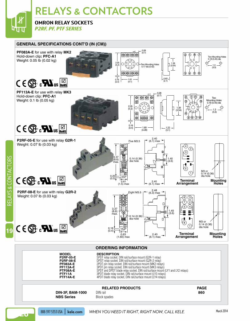
ORDERING INFORMATIONMODEL DESCRIPTIONP2RF-05-E SPDT relay socket, DIN rail/surface mount (G2R-1 relay)P2RF-08-E DPDT relay socket, DIN rail/surface mount (G2R-2 relay)PF083A-E 2PDT pin relay socket, DIN rail/surface mount (MK2 relays)PF113A-E 3PDT pin relay socket, DIN rail/surface mount (MK3 relays)PTF08A-E SPDT and DPDT blade relay socket, DIN rail/surface mount (LY1 and LY2 relays)PTF11A 3PDT blade relay socket, DIN rail/surface mount (LY3 relays)PTF14A-E 4PDT blade relay socket, DIN rail/surface mount (LY4 relays)
GENERAL SPECIFICATIONS CONT'D (IN (CM))
PF083A-E for use with relay MK2HoId-down clip: PFC-A1Weight: 0 .05 lb (0 .02 kg)
PF113A-E for use with relay MK3HoId-down clip: PFC-A1Weight: 0 .1 lb (0 .05 kg)
P2RF-05-E for use with relay G2R-1Weight: 0 .07 lb (0 .03 kg)
1 .3(3 .3)
TwoMounting Holes0 .18 (0 .45) dia
0 .16(0 .4) 1 .69
(4 .28)
0 .28(0 .7)
2 .05(5 .2) 1 .39
(3 .54)
1 .22(3 .1)
9
101112
3
4
5 6 7 8
4
3
5M3 or0 .14 (0 .36)dia hole
1 .40(3 .6)
0 .14 (0 .36)dia hole
Five M3 .5
2 .40(6 .1) max
2 .40(6 .1) max
0 .61(1 .5) max
0 .20(0 .5)
3 .37(8 .6)max .
2
1
TerminalArrangement
MountingHoles
6
7
8 M3 or0 .14 (0 .36)dia hole
1 .40(3 .6)
0 .14 (0 .36)dia hole
Eight M3 .5
2 .40(6 .1) max
2 .48(6 .3) max
0 .63(1 .60) max
0 .16(0 .4)
3 .37(8 .6)max .
3
2
45
1
TerminalArrangement
MountingHoles
P2RF-08-E for use with relay G2R-2Weight: 0 .07 lb (0 .03 kg)
0 .28(0 .7)
1 .61(4 .1)
1 .3(3 .3)
0 .83(2 .1)
2 .05(5 .2)
1 .39(3 .54)
0 .16(0 .4)
1 8 7
65
2
3 4
Two Mounting Holes0 .18 (0 .45) dia
Two Mounting Holes 0 .17 dia (0 .42)
OMRON RELAY SOCKETSP2RF, PF, PTF SERIES
RELATED PRODUCTS PAGEDIN-3F, BAM-1000 DIN rail 860NBS Series Block spades

NEW!
1129
RELAYS & CONTACTORSRELAYS & CO
NTACTORS
19
WE MAKE IT EASY. kele.com 888-397-5353 USAMarch 2014
MODEL 781 782 783 784 COIL Pull-in Voltage AC (50/60 Hz) ≤85% of nominal ≤85% of nominal ≤85% of nominal ≤85% of nominal Pull-in Voltage DC ≤80% of nominal ≤80% of nominal ≤80% of nominal ≤80% of nominal Dropout Voltage AC/DC ≥10% of nominal ≥10% of nominal ≥10% of nominal ≥10% of nominal Maximum Voltage 110% of nominal 110% of nominal 110% of nominal 110% of nominal Coil Power AC (60 Hz) 0.9VA 1.2VA 1.5VA 1.5VA Coil Power DC 0.7W 0.9W 1.7W 2.0W Duty Continuous Continuous Continuous Continuous
CONTACTS Contact Material Silver alloy Silver alloy Silver alloy Silver alloy Contact Rating 20A @ 277 VAC 15A @ 120 VAC 15A @ 120 VAC 15A @ 120 VAC 10A @ 240 VAC Gen. Purp. 12A @ 277 VAC 12A @ 277 VAC 12A @ 277 VAC 15A @ 28 VDC 12A @ 28 VDC 20A @ 28 VDC 15A @ 28 VDC 1/2 hp @ 120 VAC 1/2 hp @ 120 VAC 1/2 hp @ 120 VAC 1/2 hp @ 120 VAC 1 hp @ 250 VAC 1 hp @ 250 VAC 3/4 hp @ 250 VAC 3/4 hp @ 250 VAC Minimum load 100 mA @ 5 VDC or 0.5W 100 mA @ 5 VDC or 0.5W 100 mA @ 5 VDC or 0.5W 100 mA @ 5 VDC or 0.5W DIELECTRIC STRENGTH
Coil To Contacts 2500 Vrms 1600 Vrms 1600 Vrms 1600 Vrms
Across Open Contacts 1600 Vrms 1600 Vrms 1600 Vrms 1600 Vrms
Pole to Pole — 1600 Vrms 2500 Vrms 2500 Vrms
GENERAL Operate Time 20 msec 25 msec 25 msec 20 msec Release Time 20 msec 20 msec 20 msec 20 msec Electrical Life @ Rated Load 100,000 operations 100,000 operations 100,000 operations 100,000 operations Mechanical life @ No Load 10,000,000 operations 10,000,000 operations 10,000,000 operations 10,000,000 operations Operating Position Any Any Any Any Operating Temperature -40° to 131°F (-40° to 55°C) -40° to 131°F (-40° to 55°C) -40° to 131°F (-40° to 55°C) -40° to 131°F (-40° to 55°C) Weight 0.064 lb (0.029 kg) 0.08 lb (0.036 kg) 0.13 lb (0.06 kg) 0.18 lb (0.08kg) Agency Approvals UL-recognized component UL-recognized component UL-recognized component UL-recognized component File #E43641, CSA certified File #E43641, CSA certified File #E43641, CSA certified File #E43641, CSA certified File 40787, CE: IEC 61810-1 File 40787, CE: IEC 61810-1 File 40787, CE: IEC 61810-1 File 40787, CE: IEC 61810-1 Warranty 1 year 1 year 1 year 1 year
MAGNECRAFT RELAYS781, 782, 783, 784 SERIES
DESCRIPTIONThe Magnecraft 781, 782, 783, and 784 Series are SPDT, DPDT, 3PDT, and 4PDT plug-in style relays available with common AC and DC coil voltages . They are equipped with a mechanical flag indicator to show relay status in the manual or powered condition . Full-featured versions of these relays also include a bi-polar LED to show coil "on" or "off" status, a push button that allows momentary manual operation without the need for coil power, and a removable lock-down door that can hold the push button and relay contacts in the operate position .
FEATURES• SPDT, DPDT, 3PDT, 4PDT configurations• Flag indicator• Optional LED and momentary/maintained pushbutton• DIN rail/surface mount sockets• Mating sockets:
SPECIFICATIONS
781: 70-781D5-1A 783: 70-783D11-1 782: 70-782D8-1 784: 70-784D14-1
781
782
783
784

NEW!RELAYS & CONTACTORS
1130
NEW!RE
LAYS
& C
ONT
ACTO
RS
19
WHEN YOU NEED IT RIGHT, RIGHT NOW, CALL KELE.kele.com888-397-5353 USA March 2014
MAGNECRAFT RELAYS781, 782, 783, 784 SERIES
1.1 max(2.79)
1.2(3.08)
1.1 max(2.79)
1.6 max(4.06)
1.1 max(2.79)
0.83 max(2.10)
1.1 max(2.79)
1.60 max (4.1)
0.53(1.4)
781
in (cm)
782 783 784
1 (12)
5 (14)
9 (11)
13 (A1) 14 (A2)
781
BottomView
1 (12)
5 (14)
9 (11)
13 (A1) 14 (A2)
4 (42)
8 (44)
12 (41)
782
1 (12)
5 (14)
9 (11)
2 (22)
6 (24)
10 (21)
4 (42)
8 (44)
12 (41)
13 (A1) 14 (A2)
783
1 (12)
5 (14)
9 (11)
2 (22)
6 (24)
10 (21)
3 (32)
7 (34)
11 (31)
4 (42)
8 (44)
12 (41)
13 (A1) 14 (A2)
784
Numbers correspond to Magnecraft socket terminals. Numbers in parentheses correspond to other brand socket terminals.
Legend
NO NC
WIRING
DIMENSIONS
ORDERING INFORMATION
Model Description KIT Includes relay and mating socket. Leave blank to order the relay only. 781XAXC SPDT relay with flag indicator (requires 70-781D5-1A socket) 782XBXC DPDT relay with flag indicator (requires 70-783D11-1 socket) 783XCXC 3PDT relay with flag indicator (requires 70-783D11-1 socket) 784XDXC 4PDT relay with flag indicator (requires 70-784D14-1 socket) 12D 12 VDC coil (782XBXC only) 24D 24 VDC coil 24A 24 VAC coil 120A 120 VAC coil 240A 240 VAC coil (782XBXC only)
Example: KIT-782XBXC-24A DPDT relay with 24 VAC coil and 70-782D8-1 socket included.
KIT - -781XBXC 24A
Model Description 781XAXM4L SPDT relay with flag, LED, momentary/maintained push button (requires 70-781D5-1A socket) 782XBXM4L DPDT relay with flag, LED, momentary/maintained push button (requires 70-782D8-1 socket) 783XCXM4L 3PDT relay with flag, LED, momentary/maintained push button (requires 70-783D11-1 socket) 784XDXM4L 4PDT relay with flag, LED, momentary/maintained push button (requires 70-784D14-1 socket) 12D 12 VDC coil 24D 24 VDC coil 24A 24 VAC coil 120A 120 VAC coil 240A 240 VAC coil
Example: 782XBXM4L-24A DPDT relay with 24 VAC coil, LED, and push button (socket not included).
-782XBXM4L 24A
NEW!
1131
RELAYS & CONTACTORSRELAYS & CO
NTACTORS
19
WE MAKE IT EASY. kele.com 888-397-5353 USAMarch 2014
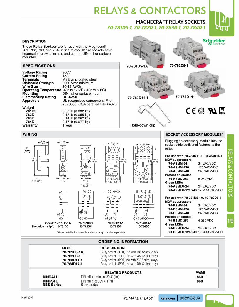
Plugging an accessory module into the socket adds additional features to the relay .
For use with 70-783D11-1, 70-784D14-1MOV suppressors 70-ASMM-24 24 VAC/VDC 70-ASMM-120 120 VAC/VDC 70-ASMM-240 240 VAC/VDCProtection diodes 70-ASMD-250 6-250 VDCGreen LEDs 70-ASMLG-24 24 VAC/VDC 70-ASMLG-120/240 120/240 VAC/VDC
For use with 70-781D5-1A, 70-782D8-1MOV suppressors 70-BSMM-24 24 VAC/VDC 70-BSMM-120 120 VAC/VDC 70-BSMM-240 240 VAC/VDCProtection diodes 70-BSMD-250 6-250 VDCGreen LEDs 70-BSMLG-24 24 VAC/VDC 70-BSMLG-120/240 120/240 VAC/VDC
MAGNECRAFT RELAY SOCKETS70-781D5-1, 70-782D-1, 70-783D-1, 70-784D-1
Voltage Rating 300VCurrent Rating 15ATerminals M3 .5 zinc-plated steelDielectric Strength 2000 Vms minimumWire Size 20-12 AWGOperating Temperature -40° to 176°F (-40° to 80°C)Mounting DIN rail or surface mountFlammability Rating UL 94V-0Approvals UL-recognized component, File
#E70550, CSA certified File #4078Weight 781D5 0 .07 lb (0 .032 kg) 782D 0 .12 lb (0 .055 kg) 783D 0 .14 lb (0 .062 kg) 784D 0 .17 lb (0 .077 kg)Warranty 1 year
DESCRIPTIONThese Relay Sockets are for use with the Magnecraft 781, 782, 783, and 784 Series relays . These sockets have fingersafe screw terminals and can be DIN rail or surface mounted .
5
1
14
9
13
70-781D5-1A
in(cm)
Socket:16-781SCHold-down clip*:
3.14(8.0)
1.18(3.0)
0.19 (0.51)
58
14
912
14 13
70-782D8-116-782SC
1.18(3.0)
2.67(6.8)
1.06(2.6)
58 6
2 14
912
14
10
13
70-783D11-116-783SC
2.67(6.8)
1.57 (4.0)1.45 (3.7)
1.10(2.8)
58 67
2 14 3
912
14
11 10
13
70-784D14-116-784SC
1.96 (5.0)
2.67(6.8)
1.81 (4.6)
1.41 (3.6)
*Order metal hold-down clip and accessory modules separately.
0.82(2.1)
0.67(1.7)
WIRING SOCKET ACCESSORY MODULES*
SPECIFICATIONS 70-781D5-1A
ORDERING INFORMATION
MODEL DESCRIPTION70-781D5-1A Relay socket, SPDT, use with 781 Series relays70-782D8-1 Relay socket, DPDT, use with 782 Series relays70-783D11-1 Relay socket, 3PDT, use with 783 Series relays70-784D14-1 Relay socket, 4PDT, use with 784 Series relays
70-782D8-1
70-783D11-1 70-784D14-1
Hold-down clip
RELATED PRODUCTS PAGEDINRALU DIN rail, aluminum, 39.4" (1m) 860DINRSTL DIN rail, steel, 39.4" (1m) 860NBS Series Block spades
NEW!RELAYS & CONTACTORS
1132
NEW!RE
LAYS
& C
ONT
ACTO
RS
19
WHEN YOU NEED IT RIGHT, RIGHT NOW, CALL KELE.kele.com888-397-5353 USA March 2014
6MM INTERFACE RELAYSRV8H SERIES
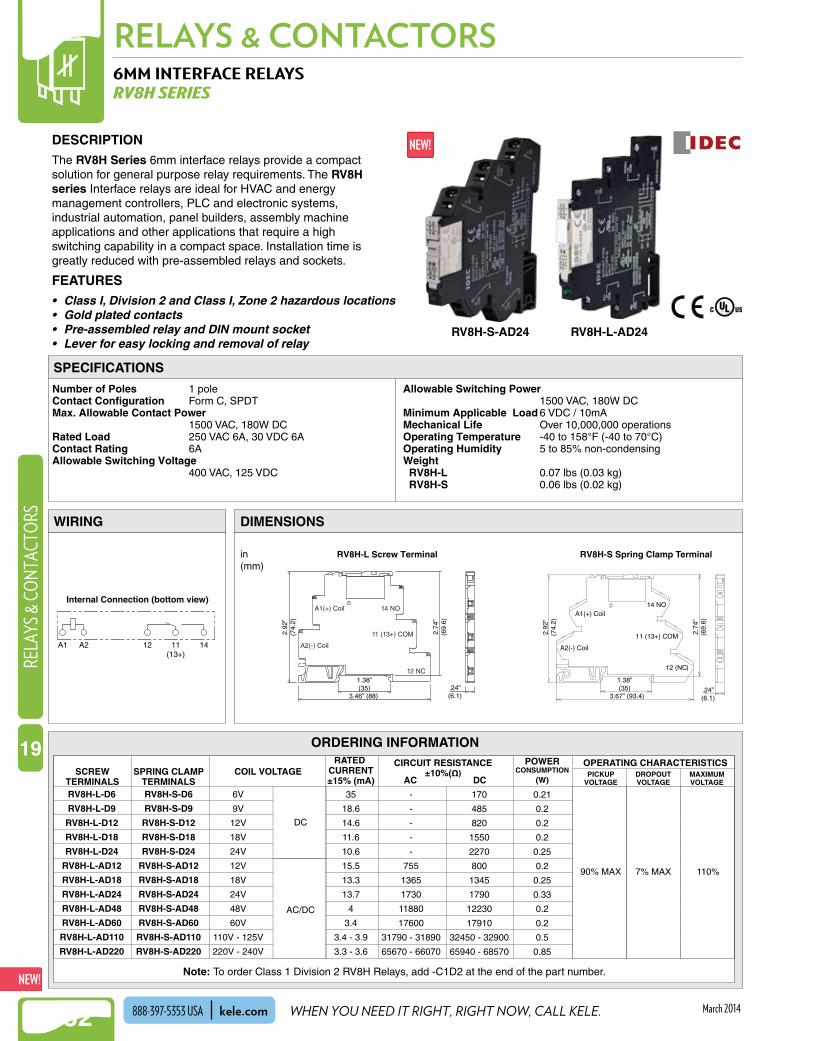
Number of Poles 1 poleContact Configuration Form C, SPDTMax. Allowable Contact Power
1500 VAC, 180W DCRated Load 250 VAC 6A, 30 VDC 6AContact Rating 6AAllowable Switching Voltage
400 VAC, 125 VDC
Allowable Switching Power 1500 VAC, 180W DC
Minimum Applicable Load 6 VDC / 10mAMechanical Life Over 10,000,000 operationsOperating Temperature -40 to 158°F (-40 to 70°C)Operating Humidity 5 to 85% non-condensingWeight RV8H-L 0 .07 lbs (0 .03 kg) RV8H-S 0 .06 lbs (0 .02 kg)
ORDERING INFORMATION
DESCRIPTIONThe RV8H Series 6mm interface relays provide a compact solution for general purpose relay requirements . The RV8H series Interface relays are ideal for HVAC and energy management controllers, PLC and electronic systems, industrial automation, panel builders, assembly machine applications and other applications that require a high switching capability in a compact space . Installation time is greatly reduced with pre-assembled relays and sockets .
FEATURES• Class I, Division 2 and Class I, Zone 2 hazardous locations• Gold plated contacts• Pre-assembled relay and DIN mount socket• Lever for easy locking and removal of relay
SPECIFICATIONS
WIRING DIMENSIONS
RV8H-L-AD24RV8H-S-AD24
AC/DC
90% MAX 7% MAX 110%
DC
RV8H-L-D6
RV8H-L-D9
RV8H-L-D12
RV8H-L-D18
RV8H-L-D24
RV8H-L-AD12
RV8H-L-AD18
RV8H-L-AD24
RV8H-L-AD48
RV8H-L-AD60
RV8H-L-AD110
RV8H-L-AD220
SCREWTERMINALS
SPRING CLAMPTERMINALS
COIL VOLTAGECIRCUIT RESISTANCE
±10%(Ω)AC DC
POWERCONSUMPTION
(W)PICKUP
VOLTAGEDROPOUTVOLTAGE
MAXIMUMVOLTAGE
OPERATING CHARACTERISTICSRATED CURRENT±15% (mA)
RV8H-S-D6
RV8H-S-D9
RV8H-S-D12
RV8H-S-D18
RV8H-S-D24
RV8H-S-AD12
RV8H-S-AD18
RV8H-S-AD24
RV8H-S-AD48
RV8H-S-AD60
RV8H-S-AD110
RV8H-S-AD220
6V
9V
12V
18V
24V
12V
18V
24V
48V
60V
110V - 125V
220V - 240V
35
18.6
14.6
11.6
10.6
15.5
13.3
13.7
4
3.4
3.4 - 3.9
3.3 - 3.6
-
-
-
-
-
755
1365
1730
11880
17600
31790 - 31890
65670 - 66070
170
485
820
1550
2270
800
1345
1790
12230
17910
32450 - 32900
65940 - 68570
0.21
0.2
0.2
0.2
0.25
0.2
0.25
0.33
0.2
0.2
0.5
0.85
RV8H-L Screw Terminal
14 NOA1(+) Coil
11 (13+) COM
A2(-) Coil
12 NC
RV8H-S Spring Clamp Terminal
14 NOA1(+) Coil
11 (13+) COM
A2(-) Coil
12 (NC)
.24”(6.1)
.24”(6.1)
2.74
”(6
9.6)
2.74
”(6
9.6)
1.38”(35)
1.38”(35)
3.46” (88) 3.67” (93.4)
2.92
”(7
4.2)
2.92
”(7
4.2)
in(mm)
Internal Connection (bottom view)
A1 A2 12 1411(13+)
Note: To order Class 1 Division 2 RV8H Relays, add -C1D2 at the end of the part number .

NEW!
1133
RELAYS & CONTACTORSRELAYS & CO
NTACTORS
19
WE MAKE IT EASY. kele.com 888-397-5353 USAMarch 2014
FUNCTIONAL DEVICES RELAY IN A BOXRIB, RIBT PILOT SERIES
Frequnecy 50/60 HzWire Length 16" (40 .6 cm)Life Rating 10 million cycles minimum
mechanicalRelay Status LED, ON - relay activatedOperating Temperature -30° to 140°F (-34° to 60°F)Operating Humidity 5-95% RH non-condensingHousing Type Plenum rated, NEMA 1, NEMA 4Conduit Hub 1/2" NPT, 3/4" NPTDimensions A size enclosures 1 .7" H x 2 .8" W x 1 .5" D
(4 .32 x 7 .11 x 3 .81 cm)B size enclosures 4 .0" H x 4 .0" W x 1 .8" D
(10 .16 x 10 .16 x 4 .57 cm)G size enclosures 2 .3" H x 3 .2"W x 1 .8" D
(5 .84 x 8 .13 x 4 .57 cm)
Approvals UL listed, UL 916 Energy Management UL 864 Fire, cUL listed, CSFM, UL File S7312
Warranty 1 year
DESCRIPTION
The Relay In A Box (RIB) Pilot Series controls most BAS, HVAC, low-horsepower motor and lighting applications . The relays come mounted and pre-wired in a housing, saving the installer the time, trouble, and expense of buying separate components (relay, socket, mounting rail, and enclosure) and assembling them on the job or at the shop .
The RIB Pilot Series has a protruding 1/2" or 3/4" NPT nipple from which all wires exit (except T series) . To install, remove a conduit knockout in the equipment, insert the wires and nipple through the hole, tighten the locknut, and connect the wires .
RIB Pilot Series - 10A RelaysThe RIB Pilot Series has relay contacts rated for 10A and is used to control light electrical loads, drive power relays/contactors, or sense the voltage being fed to electrical loads . The RIB Pilot Series requires a low coil-drive current and is provided with circuitry to allow powering the relay coil from a wide range of AC or DC voltages .
RIBT Series - High/Low Voltage SeparationThe RIBT Series is designed to provide physically separate entrances for connections to the relay input coil and output contacts . Relay contact wires exit the housing through a 1/2" or 3/4" NPT nipple . The cover of the RIBT Series is removable, and the coil drive wires can enter the housing through one of two convenient openings with star bushings or 1/2" conduit . The coil drive wires are secured to screw terminals within a separate wiring compartment in the RIBT Series . Most of the RIB's in the Pilot Series are also available in the RIBT Series .
FEATURES
• Convenient and economical to use• Relay status indicator via LED• Coil uses low current and accepts a wide range of AC
and DC voltages• Closed/Open/Auto switch option available• Nipple- or screw-mountable• Compact, gray plastic enclosure• Color-coded wires for eliminating errors• UL listed for UL916 Energy Management and UL864
Fire• Made in the USA
SPECIFICATIONS - GENERAL
RIBU1C RIBU1S
PULL-IN DROP-OUTCOIL DRIVE DC AC DC AC10-30 VAC/VDC 10 9 2.8 2.124 VAC/VDC 20 18 3.8 3120 VAC – 102 – 9208-277 VAC – 176 – 13
Coil pull-in/drop-out (nominal values)

NEW!RELAYS & CONTACTORS
1134
NEW!RE
LAYS
& C
ONT
ACTO
RS
19
WHEN YOU NEED IT RIGHT, RIGHT NOW, CALL KELE.kele.com888-397-5353 USA March 2014
FUNCTIONAL DEVICES RELAY IN A BOXRIB, RIBT PILOT SERIES
ORDERING INFORMATION
SPECIFICATIONS - PILOT SERIES
10A resistive10A resistive480 VA pilot duty480 VA ballast 600W tungsten240W tungsten1/3 hp for N.O.1/6 hp for N.C. 1/4 hp for N.O. 1/8 hp for N.C.
10A resistive 277 VAC480 VA pilot duty 277 VAC480 VA ballast 277 VAC600W tungsten 120 VAC N.O.240W tungsten 120 VAC N.C.1/3 hp for N.O. 120-240 VAC1/6 hp for N.C. 120-240 VAC1/4 hp for N.O. 277 VAC1/8 hp for N.C. 277 VAC
Status Contacton RIBU1SM and RIBH1SM:5A max @ 277 VAC
10A resistive 120-277 VAC10A resistive 28 VDC480 VA pilot duty 240-277 VAC480 VA ballast 277 VAC600W tungsten 120 VAC N.O.240W tungsten 120 VAC N.C.1/3 hp for N.O. 120-240 VAC1/6 hp for N.C. 120-240 VAC1/4 hp for N.O. 277 VAC1/8 hp for N.C. 277 VAC
10A resistive 30 VDC10A resistive 277 VAC1/2 hp for N.O. 120/240 VAC1/3 hp for N.C. 120/240 VAC
10A resistive 30 VDC10A resistive 277 VAC180 VA pilot duty 120 VAC1/8 hp for N.C. 120 VAC
Switch ratings20A 277 VAC
120/240/277 VAC28 VDC240/277 VAC277 VAC120 VAC N.O.120 VAC N.C.120/240 VAC120/240 VAC277 VAC277 VAC
Relay #1NCCOMNO
Relay #2 (if present)(gray)
(purple)
(brown)
(gray)(purple)(brown)
RELAY COILDRIVE DATA
12 mA @ 10 VDC14 mA @ 12 VDC16 mA @ 24 VDC18 mA @ 30 VDC
RIBU1C*RIBU1C-N4†
RIBU2C*
RIBH1C*RIBH1C-N4†
RIBH2C*
30 mA @ 10 VAC32 mA @ 12 VAC42 mA @ 24 VAC50 mA @ 30 VAC 25 mA @ 120 VAC35 mA @ 208-277 VAC
Relay #1Common - White/Yellow wire10-30 VAC/VDC - White/Blue wire120 VAC - White/Black wire208-277 VAC - White/Brown wireRelay #2 (if present)Common - White/Purple wire10-30 VAC/VDC - Gray/White wire120 VAC - White/Red wire208-277 VAC - White/Orange wire
RIBU1S*
RIBU2SC
RIBU2S2RIBU1SM
RIBH1S*
RIBH1SM
Relay #2 of RIBU2SCNCCOMNO
Relay #1
Relay #2
Relay #3
Relay #4 (if present)
(gray)
(purple)
(brown)
(brown)(purple)(gray)
Relay #1 (orange) (orange)
ClosedOpenAuto
ClosedOpenAuto
Relay #2 of RIBU2S2
MODEL TYPESIZE/HUB
OVR SW
RELAYCONTACT RATINGS
RELAYCONTACT WIRING
COILDRIVE
1-SPDT
2-SPDT
1-SPDT
2-SPDT
1-SPST-NO**
1-SPST-NO**
1-SPDT
2-SPST-NO**
1-SPST-NO**
1-SPST-NO**
1-SPST-NO**
A-1/2
G-3/4
A-1/2
G-3/4
–
–
–
–
Yes
Yes
Yes-2
Yes +
Status
Yes
Yes +
Status
G-1/2
G-3/4B-3/4
G-1/2
G-1/2
G-1/2
(brown)(brown)
ClosedOpenAuto
(blue)(yellow)(orange)
STATUS = 2nd Pole of switch of RIBU1SM, RIBH1SM
10-30 VAC/VDC120 VAC 50/60 Hz
10-30 VAC208-277 VAC50/60 Hz
10-30 VAC/VDC50/60 Hz
24 VAC/VDC120 VAC 50/60- Hz
24 VAC/VDC208-277 VAC50/60 Hz
10-30 VAC/VDC120 VAC50/60 Hz
10-30 VAC/VDC208-277 VAC50/60 Hz
Wiring
Input Current
(blue)
(yellow)
(orange)
(gray)(purple)(brown)
(black)(black)
(blue)(blue)
(yellow)(yellow)
(blue)(yellow)(orange)
RIBL3C 3-SPST-NO B-1/2
B-1/2
A-1/2
G-1/2
G-1/2
A-1/2
A-1/2
–
–
–
–
10-30 VAC/VDC120 VAC 50/60 Hz
10-30 VAC208-277 VAC50/60 Hz
1-SPDT
1-DPDT
1-DPDT
1-SPDT
RIBH1SC*
RIBU1SC*
RIBL4C 3-SPST-NO1-SPDT
SPDTManualSwitch
Yes-2
Yes
Yes-2
RIB2401D*RIB2401D-N4†
RIB2402DRIB2402D-N4†
NC
COM
NO
(yellow)Common
(blue) N.C.
(orange) N.O.
AutoManual
N.C. - ClosedOpen
N.O. - Closed
Common - White/Yellow wire24 VAC/VDC - White/Blue wire120 VAC - White/Black wire208-277 VAC - White/Brown wire
Common - White/Red wireRelay#1 - White/Black wireRelay#2 - White/Blue wireRelay#3 - White/Yellow wireRelay#4 - White/Brown wire (if present)
24 mA @ 18 VAC 20 mA @ 20 VDC32 mA @ 24 VAC 24 mA @ 30 VDC40 mA @ 30 VAC 36 mA @ 30 VDC31 mA @ 120 VAC (RIB2401D)36 mA @ 208-277 VAC (RIB2402D)
30 mA @ 10 VAC 12 mA @ 10 VDC32 mA @ 12 VAC 14 mA @ 12 VDC42 mA @ 24 VAC 16 mA @ 24 VDC50 mA @ 30 VAC 18 mA @ 30 VDC
NCCOMNO
NCCOMNO
NCCOMNO
SIB02S
Wiring
Wiring
Input Current
Input Current
No RelaySwitch Only
Order by model number* Models may be ordered in RIBT Series with high/low voltage separation .** Can be ordered normally closed by adding - NC after model number .† N4 has NEMA 4 housing

NEW!
1135
RELAYS & CONTACTORSRELAYS & CO
NTACTORS
19
WE MAKE IT EASY. kele.com 888-397-5353 USAMarch 2014
FUNCTIONAL DEVICES RELAY IN A BOXRIB, RIBT POWER SERIES
Frequency 50/60 HzWire Length 16" (40 .6 cm)Life Rating 10 million cycles minimum
mechanicalRelay Status LED, ON - relay activatedOperating Temperature -30° to 140°F (-34° to 60°C)Operating Humidity 5% to 95% non-condensingHousing Type NEMA 1, plenum ratedConduit Hub 1/2" NPT, 3/4" NPTDimensions A and G size enclosures 2 .3" H x 3 .2" W x 1 .8" D (5 .84 x 8 .13 x 4 .57 cm) B size enclosures 4" H x 4" W x 1 .8" D (10 .16 x 10 .16 x 4 .57 cm)
Approvals UL listed, UL 916 Energy Management, UL 864 Fire, cUL listed, CSFM, UL File S7312
Warranty 1 year
DESCRIPTIONThe Relay In a Box (RIB) Power Series controls most BAS, HVAC, low-horsepower motor and lighting applications . The relays come mounted and pre-wired in a housing, saving the installer the time, trouble and expense of buying separate components (relay, socket, mounting rail, and enclosure) and assembling them on the job or at the shop .
The RIB Power Series has a protruding 1/2" or 3/4" NPT nipple from which all wires exit (except T series) . To install, remove a conduit knockout in the equipment, insert the wires and nipple through the hole, tighten the locknut, and connect the wires .
RIB Power Series - 20, 30A RelaysThe RIB Power Series has relay contacts rated for 20 and 30A . They require modest coil drive current and are used for direct switching and control of heavy electrical circuits, such as large resistive, motor, and lighting loads .
RIBT Series - High/Low Voltage SeparationThe RIBT Series is designed to provide physically separate entrances for connections to the relay input coil and output contacts . Relay contact wires exit the housing through a 1/2" or 3/4" NPT nipple . The cover of the RIBT Series is removable and, with star bushings or 1/2" conduit, the coil drive wires can enter the housing through one of two convenient openings . The coil drive wires are secured to screw terminals within a separate wiring compartment in the RIBT . Most of the RIBs in the Power Series are also available in the T Series .
FEATURES• Convenient and economical to use• Relay status indicator via LED• Coil uses low current and accepts a wide range of AC
and DC voltages• Closed/Open/Auto switch option available• Nipple or screw mountable• Compact, gray plastic enclosure• Color-coded wires for eliminating errors• UL listed for UL916 Energy Management and UL864
Fire• Made in the USA
SPECIFICATIONS - GENERAL
RIB, RIBT Power Series
PULL-IN DROP-OUTCOIL DRIVE DC AC DC AC24 VAC/VDC 22 18 3.8 3120 VAC – 85 – 35208-277 VAC – 160 – 60480 VAC – 340 – 140
Coil pull-in/drop-out (nominal values)

NEW!RELAYS & CONTACTORS
1136
NEW!RE
LAYS
& C
ONT
ACTO
RS
19
WHEN YOU NEED IT RIGHT, RIGHT NOW, CALL KELE.kele.com888-397-5353 USA March 2014
20A resistive 277 VAC1 hp 120 VAC2 hp 277 VAC20A ballast N.O. 120/277 VAC 10A ballast N.C. 120/277 VAC 10A tungsten N.O. 120 VAC770 VA pilot duty 120 VAC1110 VA pilot duty 277 VAC
20A resistive 277 VAC1 hp 120 VAC2 hp 277 VAC20A ballast N.O. 120/277 VAC 10A ballast N.C. 120/277 VAC 10A tungsten N.O. 120 VAC770 VA pilot duty 120 VAC1110 VA pilot duty 277 VAC
(blue)(yellow)
(orange)
N.C.CommonN.O.
RELAY COILDRIVE DATA
24 VAC White/Yellow wires
125 mA @ 24 VAC 50 mA @ 24 VDC
RIB2401B*Common - White/Yellow wire24 VAC/VDC - White/Blue wire120 VAC - White/Black wire208-277 VAC - White/Brown wire
RIB2401SB*
RIB2402SB*
(orange)(orange)
ClosedOpenAuto
(orange)(orange)
(brown)(brown)
ClosedOpenAuto
MODEL TYPESIZE-HUB
OVRSW
RELAYCONTACT RATINGS*
RELAYCONTACT WIRING
COILDRIVE
1-SPDT
G-1/2
G-1/2 –
–
Wiring
Common - White/Yellow wire24 VAC/VDC - White/Blue wire120 VAC - White/Black wire208-277 VAC - White/Brown wire
Wiring
120 VAC - White/Black wires208-277 VAC - White/Brown wires480 VAC - White/Green wires
Input Current100 mA @ 120-480 VAC
Wiring
Wiring
Input Current
24 VAC/VDC White/Yellow wires120 VAC White/Black wires208-277 VAC White/Brown wires480 VAC White/Green wires
125 mA @ 24 VAC 50 mA @ 24 VDC75 mA @ 120 VAC 95 mA @ 208-277 VAC95 mA @ 480 VAC
Wiring
Input Current
75 mA @ 24 VAC 32 mA @ 24 VDC42 mA @ 120 VAC
Input Current
24 VAC/VDC - White/Yellow wires120 VAC - White/Black wires208-277 VAC - White/Brown wires480 VAC - White/Green wires
Wiring
190 mA @ 24 VAC 140 mA @ 30 VDC140 mA @ 120 VAC 170 mA @ 208-277 VAC120 mA @ 480 VAC
Input Current
24 VAC/VDC 120 VAC
24 VAC/VDC120 VAC
24 VAC/VDC
24 VAC/VDC120 VAC
24 VAC/VDC208 - 277 VAC
24 VAC/VDC 208 - 277 VAC
24 VAC/VDC 208 - 277 VAC
75 mA @ 24 VAC 32 mA @ 24 VDC42 mA @ 120 VAC62 ma @ 208/277 VAC
Input Current
RIB2402B*
Double Pole SwitchRelay Pole #1 Relay Pole #2
1-SPDT
1-SPST-NO
1-SPST-NO
–
1-SPDT
1-SPDT
G-1/2
G-1/2
Yes
Yes
RIB02S2
RIB04S2
RIB24S2*
RIB01S21-DPST-NO B-1/2
24 VAC/VDCRIB243P* 1-3PST-NO B-1/2
–120 VACRIB013P 1-3PST-NO B-1/2
–
208-277 VACRIB023P 1-3PST-NO B-1/2 –
480 VACRIB043P 1-3PST-NO B-1/2
YesDouble
Pole
RIB2401SBC* G-1/2 Yes-2
RIB2402SBC* G-1/2 Yes-2
RIB01P B-1/2 –120 VAC20A resistive 300 VAC20A resistive 28 VDC, 15 VDC15A resistive 600 VAC1 hp 120 VAC2 hp 240-277 VAC3 hp 480-600 VAC20A ballast 277-480 VAC770 VA pilot duty 120 VAC1,158 VA pilot duty 240 VAC1,110 VA pilot duty 277 VAC1,640 VA pilot duty 480 VAC
20A resistive 277 VAC1 hp 120 VAC2 hp 240-277 VAC10A tungsten 120 VAC20A ballast 277-480 VAC770 VA pilot duty 120 VAC1,110 VA pilot duty 277 VAC
1-DPDT
RIB02P B-1/2 –208-277 VAC1-DPDT
RIB04P B-1/2 –480 VAC1-DPDT
N.C.Common
N.O.
N.C.Common
N.O.
(gray)(purple)(brown)
(blue)(yellow)(orange)
RIB24P* 1-DPDT G-1/2 –
(blue)(blue)
(yellow)(yellow)
(orange)(orange)
N.O.
N.O.
N.O.
20A resistive 300 VAC20A resistive 28 VDC15A resistive 600 VAC1 hp 120 VAC, 1 PH2 hp 240-277 VAC, 1 PH3 hp 480-600 VAC 1 PH5 hp 240 VAC, 3 PH7.5 hp 480 VAC 3 PH20A ballast 277-480 VAC1466 VA 240 VAC, 3 PH2112 VA 480 VAC, 3 PH
AutoManual
N.C. - ClosedOpen
N.O. - Closed
(yellow)Common(blue)N.C.(orange)N.O.
20A resistive 277 VAC1 hp 120 VAC2 hp 277 VAC20A ballast N.O. 120/277 VAC 10A ballast N.C. 120/277 VAC 10A tungsten N.O. 120 VAC770 VA pilot duty 120 VAC1110 VA pilot duty 277 VAC
RIB24P30 1-DPDT 24 VAC/VDC A-3/4 –
N.C.Common
N.O.
N.C.Common
N.O.
(gray)(purple)(brown)
(blue)(yellow)(orange)
30A resistive 300 VAC25A resistive 28 VDC15A resistive 600 VAC1 hp 120 VAC2 hp 240-277 VAC3 hp 480-600 VAC20A ballast 277-480 VAC770 VA pilot duty 120 VAC1,158 VA pilot duty 240 VAC1,110 VA pilot duty 277 VAC1,640 VA pilot duty 480 VAC
24 VAC/VDC - White/Yellow wiresWiring
125 mA @ 24 VAC 50 mA @ 24 VDCInput Current
For normally closed, add -NC aftermodel number when ordering.
For normally closed, add -NC aftermodel number when ordering.
For normally closed, add -NC aftermodel number when ordering.
208-277 VAC
480 VAC
24 VAC/VDC
120 VAC
*Not rated for electronic ballast
FUNCTIONAL DEVICES RELAY IN A BOXRIB, RIBT POWER SERIES
SPECIFICATIONS - POWER SERIES
ORDERING INFORMATIONOrder by model number
* Models may be ordered in RIBT Series with high/low voltage separation .** Can be ordered normally closed by adding - NC after the model number .† N4 has NEMA 4 housing

NEW!
1137
RELAYS & CONTACTORSRELAYS & CO
NTACTORS
19
WE MAKE IT EASY. kele.com 888-397-5353 USAMarch 2014
RELAY IN A BOX LATCHING RELAY SERIESRIBL LATCHING SERIES
Operate Time 50 msPulse Length 30 seconds (maximum)Frequency 50/60 HzWire Type 16" (46 cm) 600 vLife Rating 1 million cycles minimum
mechanicalOperating Temperature -30° to 140°F (-34° to 60°C)Operating Humidity 5 to 95% RH non-condensingHousing Type NEMA 1, plenum ratedConduit Hub 0 .5" NPT nippleDimensionsB, SB 1 .7" x 2 .8" x 1 .5"
(4 .32 x 7 .11 x 3 .81 cm)BM, SBM 2 .3" x 3 .2" x 1 .8"
(5 .84 x 8 .13 x 4 .57 cm)Approvals UL listed, UL508, C-UL, CE, RoHSWarranty 1 year
DESCRIPTIONThe RIBL Latching Series relays are activated by pulse commands from a controller . The relay contacts are mechanically latched in the closed position and the load will remain on in the event of a control panel failure period . If power is completely lost the contacts will remain in their last state and the load will activate upon the return of normal power or emergency power .
FEATURES
• NEMA 1 Plastic enclosure• UL Listed• Energy efficient (no coil draw when relay is active)• Optional override switch• Optional status LED• Optional auxilary contacts for status control
Wht/Blu24 Vac/dc (–)
Wht/Yel24 Vac/dc (+)
Wht/Red24 Vac/dc (–)
UNLATCH
LATCH OrgLine
OrgLoad
WIRINGSPECIFICATIONS
RIBL12B
RIBL24SBM
ORDERING INFORMATION
Model Coil Voltage Coil Current Latch /Unlatch
VoltageContact
Arrangement Contact Rating LED Indication
RIBL12B
12 VAC / DC
182mA @ 10 VAC, 250mA @ 12 VAC, 165mA @ 10VDC, 198mA @ 12 VDC, 250mA @ 15VDC
Latch / Unlatch: 10 VDC / 11
VAC Minimum
One SPST latching relay,
dual coil
20A resistive @ 120-277 VAC, 20A ballast @ 120-277 VAC, 16A electronic ballast @
120-277 VAC, 5540 W tungsten @ 277 VAC, 720 VA @ 120-277
VAC, 2 hp @ 277 VAC, 3 hp @ 240 VAC, 1.5
hp @ 120 VAC
None
RIBL12BMON = Voltage detected
(contact closed)
RIBL12SB None
RIBL12SBMON = Voltage detected
(contact closed)
RIBL24B
24 VAC / DC
175mA @ 20 VAC, 210mA @ 24 VAC, 92mA @ 20VDC,
110mA @ 24 VDC, 138mA @ 30 VDC
Latch / Unlatch: 20 VDC / 22
VAC Minimum
None
RIBL24BMON = Voltage detected
(contact closed)
RIBL24SB None
RIBL24SBMON = Voltage detected
(contact closed)

NEW!RELAYS & CONTACTORS
1138
NEW!RE
LAYS
& C
ONT
ACTO
RS
19
WHEN YOU NEED IT RIGHT, RIGHT NOW, CALL KELE.kele.com888-397-5353 USA March 2014
ORDERING INFORMATION
FUNCTIONAL DEVICES RELAY IN A BOX DRY CONTACT INPUT SERIESRIB01BDC, RIB01SBDC, RIB02BDC, RIB02SBDC, RIB21CDC
Coil Rating 120 VAC @ 42 mA, 208-277 VAC @ 62 mA, 120-277 VAC @ 50 mA
Contact Rating 20A resistive @ 277 VAC 1110 VA pilot duty @ 277 VAC 770 VA pilot duty @ 120 VAC 20A ballast 277 VAC N .O . 10A ballast 277 VAC N .C 240W tungsten 120 VAC N .C . 2 hp 277 VAC 1 hp 120 VAC, 10A general use @ 250 VAC 10A resistive @ 30 VDC 1/2 hp 125-250 VAC 470 VA pilot duty 120-240 VAC
Frequency 50/60 HzControlling Contact SPST, 7 VDC, 1µA minimum
Output Type SPDT, SPST-NOWire Length 16" (40 .6 cm)Operating Temperature -30° to 140°F (-34 .4° to 60°F)Operating Humidity 5% to 95% non-condensingHousing Type NEMA 1, plemum, NEMA 1, plenumConduit Hub 1/2" NPTDimensions RIB01, RIB02
2 .3" H x 3 .2" W x 1 .8" D (5 .8 x 8 .1 x 4 .6 cm), RIB21CDC
1 .7" H x 2 .8" W x 1 .5" D (4 .3 x 7 .1 x 3 .8 cm)Approval UL File E68805Warranty 1 year
DESCRIPTION
The dry contact input RIB Series is controlled by Class 2 circuits with a dry contact from a BAS controller, thermostat, switch, another relay, or a solid-state switch . The power to energize the RIB Series comes from the load being controlled or a local power source near the relay . The relay contacts are isolated from the input power and the dry contact input .
FEATURES
• Remote power input, dry contact control• LED indication• UL listed• Optional override switch
MODEL DESCRIPTIONRIB01BDC Dry contact input RIB, 120 VAC, SPDT, 20ARIB01SBDC Dry contact input RIB, 120 VAC, SPST-NO, 20A, override switchRIB02BDC Dry contact input RIB, 208-277 VAC, SPDT, 20ARIB02SBDC Dry contact input RIB, 208-277 VAC, SPST-NO, 20A, override switchRIB21CDC Dry contact input RIB, 120-277 VAC, SPDT, 10ARIB21CDC-N4 Dry contact input RIB, 120-277 VAC, SPDT, 10A, NEMA 4 housing
SPECIFICATIONS
RIB
(blue)N.C.
Dry ContactInput (Class 2)*
Contact Output
(white/red)(white/blue)
RIB21CDC120-277 VAC
BlackNeutral or phase red
RIB01BDC120 VAC
BlackNeutral white
POWER INPUTRIB02BDC
208-277 VACBlack
Neutral or phase red (yellow)Common
(orange)N.O.
* If more than one dry contact RIB is used in common, connect all white/blue wires together
RIB
Dry ContactInput (Class 2)*
(white/red)(white/blue)
RIB01SBDC120 VAC
BlackNeutral white
POWER INPUTRIB02SBDC208-277 VAC
BlackNeutral or phase red
orangeorange
Closed
Open
Auto••
•
•
WIRING INSTALLATION
PowerInput
RelayContact
RIB located atRTU or Load
BAS Controller,Thermostat, or
Other Dry ContactSwitch
Minimum rating7 VDC, 1µA
Low-VoltageClass 2 Wiring
Starter
Power208-480 VAC
RTU orOther Load
RIB01SBDC RIB21CDC

NEW!
1139
RELAYS & CONTACTORSRELAYS & CO
NTACTORS
19
WE MAKE IT EASY. kele.com 888-397-5353 USAMarch 2014
ORDERING INFORMATION
FUNCTIONAL DEVICES LONWORKS RELAY IN A BOXRIBTW SERIES
Coil Rating 24 VAC @ 111 mA, 24 VDC @ 81 mA, 120 VAC @ 96 mA, 208-277 VAC @ 105 mA
Contact Rating 20 A resitive @ 277 VAC, 20 A ballast N .O . @ 120/277 VAC, 10 A ballast N .C . @120/277 VAC, 10 A tungsten N .O . @ 120 VAC, 1110 VA piot duty @ 277 VAC, 770 VA pilot duty @ 120 VAC, 2 hp @ 277 VAC, 1 hp @ 120 VAC
Frequency 50/60 HzRelay Type SPDT, SPST-NODuty ContinousTransceiver Type FTT-10ALED Indication Green Network status Red Relay status Yellow Service statusOperating Temperature -30° to 140°F (35° to 60°C)Operating Humidity 5% to 95% non-condensingHousing Type NEMA 1, plenum ratedConduit Hub 1/2' NPTDimensions 4"H x 4"W x 1 .8"D (10 .2 x 10 .2 x
4 .6 cm) with ½" NPT NippleApprovals UL listed file #E68805, CE certified,
LonMark 3 .3 certified, FCC, ROHSWeight 0 .82 lb (0 .38 Kg)Warranty 1 year
DESCRIPTION
The RIBTW Series of general-purpose power relays are controlled from a remote location using a LONWorks network . The relay is powered locally and communication with the network is over a twisted pair of wires . Using standard network variables (SNVTs) the relay can be commanded on and off over the network and the relay state is communicated . A separate digital input is provided to conveniently allow the state of a status feedback signal from a current switch (or other switched feedback device) to be communicated on the LONWorks network .
FEATURES
• Enclosed LonWorks relay with 20A contacts• Additional dry contact input (powered by Class 2
circuit)• Models with manual override switch• LED indication of network status, relay status and
service status• UL listed and LonMark certified, CE
LONLON
Dry contact inputClass 2 circuit24 VAC/VDC
(blue)N.C.
(yellow)Comm
(orange)N.O.
Common
(white/yellow)Neutral
(white/black)120 VAC
or (white/brown)208-270 VAC
RIBTW2401B, RIBTW2402B
LONLON
Dry contact inputClass 2 circuit 24 VAC/VDC
(orange)
Closed AutoOpen
(orange)
Common
(white/yellow)Neutral
(white/black)120 VAC
or (white/brown)208-270 VAC
RIBTW2401SB, RIBTW2402SBNOTE: When using 120, 200, or 277 VAC, there will be residual voltage on 24V terminals;
this is not intended to power external devices.
WIRING
APPLICATION
MODEL DESCRIPTIONRIBTW2401B-LN LonWorks RIB relay, SPDT, 24 VAC/VDC or 120 VAC power inputRIBTW2402B-LN LonWorks RIB relay, SPDT, 24 VAC/VDC or 208-277 VAC power inputRIBTW2401SB-LN LonWorks RIB relay, SPST-NO with manual override switch, 24 VAC/VDC or 120 VAC power inputRIBTW2402SB-LN LonWorks RIB relay, SPST-NO with manual override switch, 24 VAC/VDC or 208-277 VAC power input
SPECIFICATIONS
The relay will go to the default state when the communicationtimer times out. Setting the timer value to zero will cause thecommunication to never time out.
DESCRIPTION SNVT NAME SNVT TYPECommand to open/close relay nvi Value SNVT_switch
Command status of relay nvo Fb Value SNVT_switch
Default state of relay on/off nci Default SNVT_switch
Communication timer nci Max Receive T SNVT_elapsed_tm
Invert status of Digital-In nci Invert SNVT_lev_disc
Max time between updates nci Max Send T SNVT_elapsed_tm
Min time between updates nci Min Send T SNVT_elapsed_tm
OPEN LOOP SENSOR OBJECT
nci Invertnci Max Send Tnci Min Send T
nvoValue
NV1
NODE OBJECT
nviRequest
NV1 nvoStatus
NV2
CLOSED LOOP ACTUATOR
nci Defaultnci Max Receive T
nviValue
NV1 nvoValue Fb
NV2
RIBTW2401B

NEW!RELAYS & CONTACTORS
1140
NEW!RE
LAYS
& C
ONT
ACTO
RS
19
WHEN YOU NEED IT RIGHT, RIGHT NOW, CALL KELE.kele.com888-397-5353 USA March 2014
FUNCTIONAL DEVICES BACNET RELAY IN A BOXRIBTW2401B-BC
Supply Voltage 24 VAC @ 11 mA, 24 VDC @ 81 mA, 120 VAC @ 96 mA
Contact Rating 20A resistive @ 277 VAC, 20A ballast N .O . @ 120/277 VAC, N .C . @ 277 VAC, 10A tungsten N .O . @ 120 VAC, 1110 VA pilot duty @ 277 VAC, 770 VA pilot duty @ 120 VAC, 2 hp @ 277 VAC, 1 hp @ 120 VAC
Frequency 50/60 HzRelay Type SPDTDuty Continuous dutyLife Expectancy 10 million cycles minimumBaud Rate 9600, 19200, 38400, 57600, 76800,
and 115200LED Indication Green: network status,
Red: relay statusOperating Temperature -30° to 140°F (35° to 60°C)Operating Humidity 5% to 95% non-condensingHousing Type NEMA 1, plenum ratedConduit Hub 1/2" NPTDimensions 4" H x 4" W x 1 .8" D
(10 .2 x 10 .2 x 4 .6 cm); 1/2" NPT nipple
Approvals UL listed file #E68805, CE certified, BACnet certified
Weight 0 .83 lb (0 .38 Kg)Warranty 1 year
DESCRIPTIONThe Model RIBTW2401B-BC is an open-protocol relay controlled from a remote location using a BACnet network . These are also available in the LonWorks protocol . The relay is powered locally, and communication with the network is over a twisted pair of wires . Using standard BACnet or LonWorks objects, the relay can be commanded on and off over the network and the relay state communicated back . A separate digital input is provided to conveniently allow the state of a status feedback signal from a current switch (or other switched feedback device) to be communicated on the network . Click on the related parts and pricing tab for a more complete listing of available models .
FEATURES
• Enclosed BACnet relay with 20A contacts• Additional dry contact input (powered by Class 2
circuit)• LED indication of network status and relay status• UL listed and BACnet compatible, CE
(blue)N/C
(yellow)Comm
(orange)N/O
(white/yellow)Neutral
NOTE: When using 120 VAC, there will be residual voltage on 24V terminals;this is not to be used for powering external devices.
(white/black)120 VAC
0 1 2 3 4 5 6 7 8 9 10 1112
MS
B
LSB
Bau
dra
te
MS/TP ADDRESS
1
24 VAC/VDCCommon
Dry
con
tact
Dig
ital i
nput
MSTPR
EF
A(–
)B
(+)
Rel
ayov
errid
e
Connect jumper for terminating resistor. Disconnect for no terminating resistor.
*24 V or 120 V required but not both
WIRINGAPPLICATION
SPECIFICATIONS
RIBTW2401B-BC
ORDERING INFORMATION
MODEL DESCRIPTIONRIBTW2401B-BC BACnet RIB relay, SPDT, 24 VAC/VDC or 120 VAC power inputRIBTW2402B-BC BACnet RIB relay, SPDT, 24 VAC/VDC or 208/277VAC power input
BACnet®
Compatible Relay
Dry contact input (Class 2 circuit)
Network
24 VAC/VDC
LineNeutral
Load(orange) (yellow)
Occupancy sensor
NEW!
1141
RELAYS & CONTACTORSRELAYS & CO
NTACTORS
19
WE MAKE IT EASY. kele.com 888-397-5353 USAMarch 2014
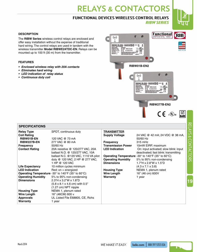
FUNCTIONAL DEVICES WIRELESS CONTROL RELAYSRIBW SERIES
DESCRIPTION
The RIBW Series wireless control relays are enclosed and offer easy installation without the expense of traditional hard wiring . The control relays are used in tandem with the wireless transmitter Model RIBWE24TDC-EN . Relays can be mounted up to 100 ft (30 m) from the transmitter .
FEATURES
• Enclosed wireless relay with 20A contacts• Eliminates hard wiring• LED indication of relay status• Continuous duty coil
Relay Type SPDT, continuous dutyCoil Rating RIBW01B-EN 120 VAC @ 73 mA RIBW227B-EN 277 VAC @ 80 mAFrequency 50/60 HzContact Rating 20A resistive @ 120/277 VAC, 20A
ballast N .O . @ 120/277 VAC, 10A ballast N .C . @120 VAC, 1110 VA pilot duty @ 120 VAC, 2 HP @ 277 VAC,
1 HP @ 120 VACLife Expectancy 10 million cycles minimumLED Indication Red: on = energizedOperating Temperature -30° to 140°F (35° to 60°C)Operating Humidity 5% to 95% non-condensingDimensions 2 .3"H x 3 .2"W x 1 .8"D (5 .8 x 8 .1 x 4 .6 cm) with 0 .5" (1 .27 cm) NPT nippleHousing Type NEMA 1, plenum ratedWire Length 16" (46CM) 600 v Approvals UL Listed File E68805, CE, RohsWarranty 1 year
TRANSMITTERSupply Voltage 24 VAC @ 42 mA; 24 VDC @ 38 mA,
50/60 HzFrequency 315 mHzTransmission Power 10mW EIRP, maximumLED Indication On: input activated; slow blink: input
deactivated; fast blink: transmittingOperating Temperature -30° to 140°F (35° to 60°C)Operating Humidity 5% to 95% non-condensingDimensions 1 .7"H x 2 .8"W x 1 .5"D (4 .3 x 7 .1 x 3 .8)Housing Type NEMA 1, plenum ratedWire Length 16" (46 cm) 600V Warranty 1 year
SPECIFICATIONS
RIBW277B-EN2
RIBW01B-EN2

NEW!RELAYS & CONTACTORS
1142
NEW!RE
LAYS
& C
ONT
ACTO
RS
19
WHEN YOU NEED IT RIGHT, RIGHT NOW, CALL KELE.kele.com888-397-5353 USA March 2014
ORDERING INFORMATION
FUNCTIONAL DEVICES WIRELESS CONTROL RELAYSRIBW SERIES
WIRING
(blue)
(orange)
(black)120 or277 VAC
(white)Neutral
Wirelessreceivercontrolunit
Relay Wiring
Wireless transmitter control unit
(white/yellow)24 VAC/VDC
(white/blue)
(white/yellow)24 VAC/VDC
Dry contact input
(white/red)
Low voltage control input
(white/black)
(white/black)
Wirelesstransmission
Transmitter Wiring
MODEL DESCRIPTIONRIBW01B-EN2 2-way wireless encl relay dry-contact, 20A 120 VACRIBW24B-EN2 2-way wireless encl relay dry-contact, 20A 24 VACRIBW208B-EN2 2-way wireless encl relay dry-contact, 20A 208 VACRIBW240B-EN2 2-way wireless encl relay dry-contact, 20A 240 VACRIBW277B-EN2 2-way wireless encl relay dry-contact, 20A 277 VACRIBWE24TDC-EN2 Wireless trasmitter for RIB relays
RELATED PRODUCTS PAGEWWS Series Wireless switch transmitter 679WWS Series switch cover WWS Series swtich cover plates 679

NEW!
1143
RELAYS & CONTACTORSRELAYS & CO
NTACTORS
19
WE MAKE IT EASY. kele.com 888-397-5353 USAMarch 2014
Relay sections (snap-apart)
Contact type
Voltage input
Contact rating
MR-100 MR-200SERIES
MR-600 MR-8001 or 4 1, 4, or 8
24 VDC @ 18 mA24 VAC @ 18 mA
120 VAC @ 18 mA230 VAC @ 18 mA
24 VDC @ 40 mA24 VAC @ 40 mA
120 VAC @ 40 mA230 VAC @ 40 mA
24 VAC, 24 VDC @15 mA
24 VDC @ 22 mA 24 VAC @ 60 mA
120 VAC @ 20 mA
SPDT SPDTDPDT10A resistive @ 120 VAC
7A resistive @ 230 VAC/28 VDCN.O.: 1/6 hp @ 120 VAC N.C.: 1/8 hp @ 120 VAC
10A @ 120 VAC7A @ 24 VDC
10A @ 120 VAC 7A @ 30 VDC/277 VAC
1/4 hp @ 120 VAC 1/3 hp @ 230 VAC
32° to 120°F (0° to 49°C) 32° to 120°F (0° to 49°C)
LED
Solid or stranded, 12 to 22 AWG terminals
18-gauge metal back, ABS-94VO plastic cover1/2" knockouts
On/Auto/Off Switch
–
–
–
–
3.25"H x 2.13"W x 1.5"D (8.25 x 5.39 x 3.81 cm)5.13"H x 3.13"W x 2.5"D (13 .46 x 7.95 x 6.35 cm) or5.13"H x 9.5"W x 2.5"D (13.46 x 24.13 x 6.35 cm)
3.5"H x 2.13"W x 1.38"D (8.9 x 5.4 x 3.5 cm)
UL-recognized component, File #S3403Enclosed model UL listed, File #S3403
UL-recognized component,File #S3403
* Specifications are for each relay section.
Temperature
WiringTrack or enclosed Track Track or spacerMounting
Indication
Manual override
Enclosure option
DimensionsEnclosure dimensions
Agency approvals
SPECIFICATIONS
AIR PRODUCTS AND CONTROLS MULTI-VOLTAGE CONTROL RELAYSMR SERIES
DESCRIPTIONThe MR Series multi-voltage control relays offer SPDT or DPDT contacts which may be operated by multiple input control voltages .Each relay section contains a red LED, which indicates the relay coil is energized . Relay sections may be snapped apart from standard four- or eight-section assemblies and used independently .These relays are ideal for applications where local or remote contacts are required for control of electrical loads and general-purpose switching . They are suitable for use with HVAC, temperature control, fire alarm, security, building automation, and lighting control systems .
FEATURES• Multi-voltage input, SPDT or DPDT control relays• LED indication when relay is energized• Snap-apart relay sections from standard four or eight-
section assemblies• Track, spacer, or enclosed mounting options• Dust-proof housing with LED viewing holes on
enclosed models• Relays rated for 10 million mechanical operations
MR-101/T MR-601/T
MR-801/S
MR-101/C MR-104/T

NEW!RELAYS & CONTACTORS
1144
NEW!RE
LAYS
& C
ONT
ACTO
RS
19
WHEN YOU NEED IT RIGHT, RIGHT NOW, CALL KELE.kele.com888-397-5353 USA March 2014
AIR PRODUCTS AND CONTROLS MULTI-VOLTAGE CONTROL RELAYSMR SERIES
Ø 18/24 115 230
NC C NO
SPDT Contacts10A @
120 VAC
RelayEnergizedIndicator
MR-101, -104
InputControlVoltage
24 VDC
24 VAC
120 VAC
230 VAC
(–) (+)
A.C. A.C.
L1
H
L2
N
Terminal strip connections
NC C NO
SPDT Contacts10A @
120 VAC
Ø 18/24 115 230
NC C NO
DPDT Contacts10A @
120 VAC
RelayEnergizedIndicator
MR-201, -204 MR-601, -604, -608
InputControlVoltage
24 VDC
24 VAC
120 VAC
230 VAC
(–) (+)
A.C. A.C.
L1
H
L2
N
InputControlVoltage
24 VDC
24 VAC
120 VAC
(+)
N
AC
(–)
AC
H
Terminal strip connections
NC C NORelay
EnergizedIndicator
Supply24 VAC24 VDC
24 VAC/VDCControlInput
Common
NC C NO
SPDT Contacts10A @
120 VAC
MR-801, -804, -808
RelayEnergizedIndicator
Terminal strip connections
ON
AU
TOO
FF
SUP CTL COMØ 24 115
Note: Multisection relays MR-604 and MR-608 have all supply and all common terminals factory jumpered together.
WIRING
ORDERING INFORMATION
MR-101/TMR-101/CMR-104/TMR-104/CMR-201/TMR-201/CMR-204/TMR-204/CMR-601/TMR-604/TMR-608/TMR-801/TMR-801/SMR-804/TMR-804/SMR-808/TMR-808/S
COIL VOLTAGE SECTIONS MOUNTING SWITCH AGENCY APPROVALS
24 V
DC
24 V
AC
120
VAC
230
VAC
UL
ME
A
CS
FM
SP
DT
(10
A)
DP
DT
(10
A)
Man
ual
Ove
rrid
eO
n/A
uto
/Off
MODEL
XXXXXXXXXXXXXXXXX
RecognizedListedRecognizedListedRecognizedListedRecognizedListedRecognizedRecognizedRecognizedRecognizedRecognizedRecognizedRecognizedRecognizedRecognized
X
X
X
X
XXXXXXXX
XXXXXXXXXXXXXXXXX
XXXXXXXX
XXXXXX
XXXXXXXX
1144
148114488
1144
XXXXXXXXXXXX
X
X
X
X
X
X
X
X
XXXX
Trac
k(i
ncl
ud
ed)
Sp
acer
s(i
ncl
ud
ed)
En
clo
sure
(in
clu
ded
)

NEW!
1145
RELAYS & CONTACTORSRELAYS & CO
NTACTORS
19
WE MAKE IT EASY. kele.com 888-397-5353 USAMarch 2014
FUNCTIONAL DEVICES MODULAR PANEL RELAYSRIB M SERIES
Frequency 50/60 HzLife Rating 10 million cycles minimum
mechanicalRelay Status LED, ON - relay activatedOperating Temperature -30° to 140°F (-34° to 60°C)Operating Humidity 5% to 95% non-condensingDimensions C 1 .75"H x 4"W x 1 .25"L (4 .45 x 10 .16 x 3 .18 cm) D 1 .75"H x 4"W x 2"L (4 .45 x 10 .16 x 5 .08 cm) F 1 .75"H x 4"W x 2 .45"L (4 .45 x 10 .16 x 6 .22 cm) H 1 .75"D x 2 .75"W x 1 .25"L (4 .45 x 6 .99 x 3 .18 cm) I 1 .75"D x 2 .75"W x 1 .7"L (4 .45 x 6 .99 x 4 .32 cm) J 1 .75"D x 4"W x 1 .5"L (4 .45 x 10 .16 x 3 .85 cm) K 1 .75"D x 2 .75"W x 2 .5"L (4 .45 x 6 .99 x 6 .35 cm)
L 1 .75"D x 2 .75"W x 1 .25"L (4 .45 x 6 .99 x 8 .64 cm) MH1000 14 .5"H x 7 .7"W x 3 .9"D (36 .83 x 19 .56 9 .91 cm) MH3500 24 .5"H x 10 .25"W x 3 .9"D (62 .23 x 26 .04 x 9 .91 cm) MH38000 24 .5"H x 12 .5"W x 6 .5"D (62 .23 x 31 .75 x 16 .5 cm)Approvals UL listed, UL 916 Energy
Management, UL 864 Fire, cUL listed, CSFM . UL FIle E68805
Warranty 1 year
DESCRIPTION
The RIB M Series modular relay system allows the installer to mount a combination of relays in an attractive metal enclosure . Models are available to control most BAS, HVAC, low-horsepower motors and lighting applications . The relay modules snap into a 4" (10 .16 cm) wide plastic track . This system provides a convenient and cost-saving method of mixing and matching relays of different ratings to suit the requirements of the application .Connections to the modules are made by wiring to screw terminals . Input connections can be grouped on one side of the enclosure and output connections on the other to separate high-voltage and low-voltage wires . Plenty of room is provided within the enclosure for wire runs, and the housings can be stacked vertically or horizontally . The relay modules can be snap-track mounted inside the housing as pictured or mounted into an available space in other equipment . The track is available in 2" (5 .08 cm) lengths for mounting one module or in 12" (30 .5 cm) lengths for mounting several modules .
RIBM Pilot Series - 10A, 15A modular relaysThese pilot modular relays have contacts rated up to 15A and are used to control light electrical loads, drive power relays/contactors or to sense the voltage fed to electrical loads . The pilot modular relays require a low coil drive current and are provided with circuitry to allow powering the relay coil from a wide range of AC or DC voltages .
RIBM Power Series - 30A modular relaysThe power modular relays have contacts rated up to 30A . They require modest coil drive current and are used for direct switching and control of heavy electrical circuits such as large resistive, motor, or lighting loads .
FEATURES• Convenient and economical to use• Handy, track-mounted modules• Attractive, stackable metal enclosure• Relay status indicator via LED• Coil uses low current and accepts wide range of AC &
DC voltages• Closed/Open/Auto switch option available• High density relay packaging• UL listed enclosure and relay modules
SPECIFICATIONS
RIB M Series (shown in optional
enclosure)
PULL-IN DROP-OUTCOIL DRIVE DC AC DC AC10-30 VAC/VDC 10 9 2 .8 2 .124 VAC/VDC 22 18 3 .8 3120 VAC – 85 – 35208-277 VAC – 160 – 60
Coil pull-in/drop-out (nominal values)

NEW!RELAYS & CONTACTORS
1146
NEW!RE
LAYS
& C
ONT
ACTO
RS
19
WHEN YOU NEED IT RIGHT, RIGHT NOW, CALL KELE.kele.com888-397-5353 USA March 2014
DPST-NO
DPST-NO
–
Yes-2
–
Yes-2
–
Yes
24 VAC/VDC
24 VAC/VDC120 VAC50/60 Hz
24 VAC/VDC208-277 VAC50/60 Hz
24 VAC/VDC120 VAC
24 VAC/VDC208-277 VAC
20A resistive 277 VAC1 hp 120 VAC2 hp 277 VAC20A ballast N.O. 120-277 VAC10A ballast N.C. 120-277 VAC10A tungsten N.O. 120 VAC770 VA pilot duty 120 VAC1,110 VA pilot duty 277 VAC
20A resistive 300 VAC, 28 VDC15A resistive 600 VAC1 hp 120 VAC2 hp 240-277 VAC3 hp 480-600 VAC20A ballast 277-480 VAC770 VA pilot duty 120 VAC1,158 VA pilot duty 240 VAC1,110 VA pilot duty 277 VAC1,640 VA pilot duty 480 VAC24ZL and 24ZN: 30A res.@ 300 VAC
24 VAC/VDCCOMMON
NCCOMNO
RIBM2401B
RIBM2401SBC
RIBM2402B
RIBM2402SBC
RIBM2401SB
RIBM2402SB
RIBM24PL
RIBM24ZL
1-SPDT
1-SPST-NO
C
F
F
D
45 mA @ 18 VAC 30 mA @ 22 VDC75 mA @ 24 VAC 32 mA @ 24 VDC42 mA @ 120 VAC 42 mA @ 30 VDC62 mA @ 208-277 VAC
100 mA @ 20 VAC 50 mA @ 24 VDC125 mA @ 24 VAC 70 mA @ 30 VDC
Closed
Open
AutoPosition of yellow jumperselects N.O. vs N.C.
either - 208-277 VACor - 120 VAC 24 VAC/VDC Common
NO
NCCOMNO
Relay Without Override Switch
Relay With Override Switch
Common
N.C.
N.O.
AutoManual
N.C. - ClosedOpen
N.O. - Closed
C
F
Wiring
Wiring
Current Input
Current Input
–FDPDTRIBM24ZN 24 VAC/VDC
NC
COM
NO
Relay #2 (if present)
Relay #1 (and #2 if present)
COIL DRIVE DATA
RIBMU1CRIBMU1SCRIBMNU1C
Relay #1
U1S and H1S
NCCOMNO
NCCOMNO
Closed
Open
Auto
Closed
Open
Auto
Closed
Open
Auto
Closed
Open
Auto
MODEL TYPE SIZE* OVR CONTACT RATINGS CONTACT WIRINGCOIL DRIVE
1-SPDT
1-SPST
–
Yes
U1SM and H1SM
24 VAC/VDC50-60 Hz
10-30 VAC/VDC 208-277 VAC50-60 Hz
10-30 VAC/VDC120 VAC50-60 Hz
10-30 VAC/VDC 208-277 VAC50-60 Hz
10-30 VAC/VDC120 VAC50-60 Hz
Wiring
Wiring
Current Input
15A general use 125 VAC10A general use 250 VAC10A resistive 30 VDC1/2 hp 125/250 VAC470 VA pilot duty 120/240 VAC
10A resistive 120/240/277 VAC15A resistive 150 VAC, 28 VDC15A inductive 150 VAC480 VA pilot duty 240/277 VAC480 VA ballast 277 VAC600W tungsten 120 VAC N.O.240W tungsten 120 VAC N.C.1/3 hp for N.O. 120/240 VAC1/6 hp for N.C. 120/240 VAC1/4 hp for N.O. 277 VAC1/8 hp for N.C. 277 VAC
10A resistive 277 VAC15A resistive 150 VAC480 VA pilot duty 277 VAC480 VA ballast 277 VAC600W tungsten 120 VAC N.O.240W tungsten 120 VAC N.C.1/3 hp for N.O. 120/240 VAC1/6 hp for N.C. 120/240 VAC1/4 hp for N.O. 277 VAC1/8 hp for N.C. 277 VAC
Status
Status
24C 24S
*Cut appropriate jumper to select N.C. or N.O.
**For normally closed contacts, specify NC after model number
Yes
Yes +
Yes
Yes+
24 VAC/VDC
Current Input30 mA @ 10 VAC 12 mA @ 10 VDC32 mA @ 12 VAC 14 mA @ 12 VDC42 mA @ 24 VAC 16 mA @ 24 VDC50 mA @ 30 VAC 18 mA @ 30 VDC25 mA @ 120 VAC35 mA @ 208-277 VAC
eitheror
208-277 VAC120 VAC
10-30 VAC/VDCCommon
**
*
RIBMH2C 2-SPDT
1-SPST-NO
1-SPST-NO
1-SPST-NO
1-SPST-NO
* See Specification on previous page for dimensions.
RIBM24C
RIBMN24C
RIBMU1SRIBMNU1S
F
F
1-SPDT
1-SPDT
C
HC
C
CKDLCK
C
H
D
RIBM24S
RIBMN24S
RIBMU2CRIBMH1C
2-SPDT –
–
Yes-2
–
–
–
Yes-2–
J
JRIBMNH1CRIBMH1SC
RIBMH1SMRIBMNH1SM
RIBMH1SRIBMNH1S
RIBMU1SMRIBMNU1SM
Relay Without Override Switch
Relay With Override Switch
Common
N.C.
N.O.
AutoManual
N.C. - ClosedOpen
N.O. - Closed
STATUS 50 VAC/VDC max and0.25 A max
I
I
L
24 mA @ 20 VAC 13 mA @ 20 VDC28 mA @ 24 VAC 16 mA @ 24 VDC44 mA @ 35 VAC 25 mA @ 35 VDC
FUNCTIONAL DEVICES MODULAR PANEL RELAYSRIB M SERIES
SPECIFICATIONS - PILOT RELAY MODULES
SPECIFICATIONS - POWER RELAY MODULES
ORDERING INFORMATION
ACCESSORIESMH1000 Screw-cover housingMH3500 Hinge-cover housingMH3800 Hinge-cover housingMT212-12 Relay track, 12" x 2.75" (30.48 x 6.99 cm)MT212-2 Relay track, 2" x 2.75" (5.08 x 6.99 cm)MT4-12 Relay track, 12" x 4" (30.48 x 10.16 cm)MT4-2 Relay track, 2" x 4" (5.08 x 10.16 cm)

NEW!
1147
RELAYS & CONTACTORSRELAYS & CO
NTACTORS
19
WE MAKE IT EASY. kele.com 888-397-5353 USAMarch 2014
Coil Rating PAM-1 24 VAC @ 31 mA, 24 VDC @ 15 mA,
120 VAC @ 19 mA PAM-4 9-40 VDC @ 15 mAContact Rating SPDT, Form C, 10A @120 VAC, 7A
@ 24 VDC, 250µA @ 5 VDCWire Size 12" (30 .5 cm), 18 AWGOperating Temperature -58° to 185°F (-50° to 85°C)Mounting Pre-drilled mounting screw hole and
mounting screw provided; double-sided tape also provided
Dimensions 1 .5"H x 1"W x 0 .9"D (3 .81 x 2 .54 x 2 .2 cm)
Approvals UL listed File #S3403, CSFM, MEAWeight 0 .15 lb (0 .068 kg)Warranty 1 year
AIR PRODUCTS AND CONTROLS MULTI-VOLTAGE RELAY MODULESPAM-1, PAM-4
DESCRIPTIONPAM Series relays are small encapsulated multi-voltage modules that provide 10A Form C contacts .These devices are ideal for applications where remote relays are required for control or status feedback . They are suitable for use with HVAC, temperature control, fire alarm, security, building automation, and lighting control systems .
PAM Series relays may be mounted by using double-sided adhesive tape (provided), a self-drilling screw, or they may be loosely placed in a handy box .
FEATURES• Multi-voltage input• Small size• Multiple mounting options• Wirenuts, mounting screw, and tape included• LED indication (PAM-1 only)
9-40 VDC@ 15 mA
(red)
(black)
(blue)
(yellow)
(orange)
(+)
(+)
(-)
(–)
10AContacts
C
N.C.
N.O.
Mounting Hole
24 VAC/VDC
120V*
(white)
(red)
(black)
(blue)
(yellow)
(orange)
10AContacts
C
N.C.
N.O.
Mounting Hole
Relay Energized LED
PAM-1 PAM-4* May not be suitable for continuous duty use at 120 VAC for extended periods of time.
WIRING
PAM-1
ORDERING INFORMATION
PAM-4
SPECIFICATIONS
MODEL DESCRIPTIONPAM-1 Multi-voltage relay module, 24 VAC/VDC, 120 VACPAM-4 Multi-voltage relay module, 9-40 VDCPAM-2 Multi-voltage relay module, 12 or 24 VDCPAM-SD Multi-voltage relay module, 20-32 VDC

NEW!RELAYS & CONTACTORS
1148
NEW!RE
LAYS
& C
ONT
ACTO
RS
19
WHEN YOU NEED IT RIGHT, RIGHT NOW, CALL KELE.kele.com888-397-5353 USA March 2014
DESCRIPTIONThe KE375 and KE900 Series of 30A relays are heavy duty power relays commonly used for energy management, refrigeration, and HVAC control applications . High power handling capability and small size make these power relays particularly suited for motor control, heater loads, and lighting control . The KE900 Series features an open frame construction, and the KE375 is encased in a clear polycarbonate cover .
FEATURES• Small size• High-power handling capability• One-, two-, and three-pole models• 24 VAC, 24 VDC & 120 VAC coils
KE375
KE900D
KE900 KE375
24 VAC/60 Hz, 120 VAC/60 Hz, or 24 VDC
3/16" dia mounting holes Top-mount cover with slotted tabs
30A or 1-1/2 hp @ 120 VAC / 240 VAC20A or 2 hp @ 600 VAC30A @ 28 VDC, resistive3600W @ 120 or 240V (ballast)2 hp @ 240 VAC20A @ 600 VAC20A @ 125 VDC (D models only)
30A @ 300 VAC, 80% PF15A @ 600 VAC, 80% PF30A @ 28 VDC1 hp @ 120 VAC2 hp @ 240 VAC / 277 VAC3 hp @ 480/600 VAC, 100,000 cycles20A @ 277/480 VAC ballast, 6000 cycles
AC: 9.5 VA sealedDC: 2.0W
AC: 4.6 VA DC: 2.6W
AC: 85% or less of nominalDC: 75% or less of nominal
Coil voltage
Coil power
Pull-in voltage
Contact ratings
MountingTerminalsContact materialDielectric strength
Screw terminals
30 ms
10 oz (283g)
15 ms
3.5 oz (99g)
Silver cadmium oxide
2200V RMS between contacts2200V RMS between other elements
2200V RMS between contacts3750V RMS between other elements
UL/cUL listed, File #E37066 UL/cUL-recognized component, File #E37066;CE certified
0.25" x 0.032" quick connects
Operate/Release time
WeightAgency approvals
SPECIFICATIONS
KE900S
POWER RELAYSKE375, KE900 SERIES

NEW!
1149
RELAYS & CONTACTORSRELAYS & CO
NTACTORS
19
WE MAKE IT EASY. kele.com 888-397-5353 USAMarch 2014
POWER RELAYSKE375, KE900 SERIES
A
1
4
3
6
7 9
B
2
5
81 .40(3 .56)
2 .13(5 .41)
3 .16(8 .03)
2 .75(6 .99)
2 .35(5 .97)
0 .17(0 .43)
0 .06(0 .16)
KE375T
KE900S KE900D KE375T
6
5
3
8
6
4
7
5
3
1
4
7
2
5
8
3
6
9
2 1 2 1 A B
NC
NO
C
NC
NO
C
NC
NO
C
WIRING
DIMENSIONS
ORDERING INFORMATION
MODEL DESCRIPTIONKE375T120VAC 3PDT Power relay 120 VAC coilKE375T24VAC 3PDT Power relay 24 VAC coilKE375T24VDC 3PDT Power relay 24 VDC coilKE900S120VAC SPDT Power relay 120 VAC coilKE900S24VAC SPDT Power relay 24 VAC coilKE900S24VDC SPDT Power relay 24 VDC coilKE900D120VAC DPDT Power relay 120 VAC coilKE900D24VAC DPDT Power relay 24 VAC coilKE900D24VDC DPDT Power relay 24 VDC coil
2 .2(5 .59)
2 .38(6 .04)
3 .32(8 .43)
2 .50(6 .35)
6-32 Screw (2) Coil TerminalsTwo Mounting Holes 0 .19 (0 .48) dia
8-32 Screw(2) Contact Terminals
1 .66(4 .22)
1 .88(4 .76)2 .50
(6 .35)1 .88
(4 .76)
Two Holes0 .19 (0 .48) dia
2 .50(6 .35)
6-32 Screw(2) Coil Terminals
KE900S KE900D
8-32 Screw(6) Contact Terminals
0 .81(2 .08)
in(cm)

NEW!RELAYS & CONTACTORS
1150
NEW!RE
LAYS
& C
ONT
ACTO
RS
19
WHEN YOU NEED IT RIGHT, RIGHT NOW, CALL KELE.kele.com888-397-5353 USA March 2014
Coil Voltage 24V, 26 .4V maximum,120V 50/60 Hz .132V maximum
Coil Power AC:2 .5 VA, DC: 2 .0WPull In Voltage 18V, 75VDrop Out Voltage 3 .6V, 18V, 20VContact Rating G7L-1A: Resistive: 30A, 277 VAC
General purpose: 25A, 277 VAC 30A 120 VAC Tungsten: 1 .5 kW, 120 VAC Horsepower: 1 .5 hp, 120 VAC 3 hp, 277 VAC, G7L-2A: Resistive: 25A, 277 VAC General purpose: 25A, 277 VAC 25A 120 VAC Tungsten 1 .3 kW, 120 VAC Horsepower 1 hp, 120 VAC 2 hp, 277 VAC
Contact Resistance 50 mΩ maximumTerminals 0 .25" x 0 .031" quick connectsContact Material Silver cadmium oxideDielectric Strength 2000 VAC between contacts, 4000
VAC between coil and contactsOperate Time 30 ms maximumRelease Time 30 ms maximumOperating Temperature -13° to 140°F (-25° to 60°C)Mounting Top-mount cover with slotted tabs
or DIN rail surface-mount socket with screw terminals
Approvals UL-recognized component, File #E41643: CSA certified, File #LR35535: CE certifed
Weight 0 .2 lb (0 .091 kg)Warranty 1 year
ORDERING INFORMATION
OMRON POWER RELAYSG7L SERIES
0.43(1.1)
0.12(0.3)
2.69(6.85) max2.36(6.0)
1.99 (5.05) max
2.36 ±.007(6.0 ±0.02) 2.2 (5.6)
1.32(3.35) max 0.078
(0.2)0.031(0.08)
0.177(0.45)
0.25 (0.64) max
Two Mounting Holes0.177 (0.45) dia
or M4 tapped holes
1.85(4.7)max
2.1(5.3)
in(cm)
Depth: 1.0 (2.54)
P7LF-06G7L-1A, -2A
G7L-1A, 2AG7L-1A, -2A
DESCRIPTION
G7L Series relays are heavy duty power relays commonly used for controlling refrigeration, HVAC equipment, heater loads, and lighting controls . High-power handling capability up to 30A, small size, and low cost characterize these relays . They are available in single and double pole models and are surface mounted or DIN rail mounted with the PL7F-06 socket .
FEATURES
• High power capability• Small size• Low cost• Push-to-test button• Optional DIN rail screw terminal socket
0 1
4 6
0 1
2 4 6 8
G7L-1A-TUBJ-CB G7L-2A-TUBJ-CB
WIRING
MODEL DESCRIPTIONG7L-1A-TUBJ-CB-24VAC SPST-N.O. Power relay 24 VACG7L-1A-TUBJ-CB-24VDC SPST-N.O. Power relay 24 VDCG7L-1A-TUBJ-CB-120VAC SPST-N.O. Power relay 120 VACG7L-2A-TUBJ-CB-24VAC DPST-N.O. Power relay 24 VACG7L-2A-TUBJ-CB-24VDC DPST-N.O. Power relay 24 VDCG7L-2A-TUBJ-CB-120VAC DPST-N.O. Power relay 120 VAC
DIMENSIONS
G7L SeriesSPECIFICATIONS
RELATED PRODUCTS P7LF-06 DIN rail/surface mount socket

NEW!
1151
RELAYS & CONTACTORSRELAYS & CO
NTACTORS
19
WE MAKE IT EASY. kele.com 888-397-5353 USAMarch 2014
ORDERING INFORMATION
MODEL FULL-LOAD AMP (FLA) LOCKED-ROTOR AMP (LRA) RESISTIVE HP, SINGLE PHASE HP, THREE PHASE
DPC24A2D30DPC01A2D30DPC02A2D30
30 FLA @ 240-600 VAC 180 LRA @ 240/277 VAC150 LRA @ 480 VAC120 LRA @ 600 VAC
40A @ 240-600 VAC 2 hp @ 120 VAC3 hp @ 240 VAC
DPC24A2D40DPC01A2D40
40 FLA @ 240-600 VAC 240 LRA @ 240/277 VAC200 LRA @ 480 VAC160 LRA @ 600 VAC
50A @ 240-600 VAC 2 hp @ 120 VAC3 hp @ 240 VAC
DPC24A3C30DPC01A3C30
30 FLA @ 240-600 VAC 180 LRA @ 240/277 VAC150 LRA @ 480 VAC120 LRA @ 600 VAC
40A @ 240-600 VAC 2 hp @ 120 VAC5 hp @ 240/277 VAC
DPC24A3C40DPC01A3C40
40 FLA @ 240-600 VAC 240 LRA @ 240/277 VAC200 LRA @ 480 VAC160 LRA @ 600 VAC
50A @ 240-600 VAC 3 hp @ 120 VAC7 .5 hp @ 240/277 VAC
DPC24A3B50DPC01A3B50
50 FLA @ 240-600 VAC 300 LRA @ 240 VAC250 LRA @ 480 VAC200 LRA @ 600 VAC
65A @ 240-600 VAC 3 hp @ 120 VAC7 .5 hp @ 200/208 VAC10 hp @ 240 VAC
——————
10 hp @ 200/208 VAC10 hp @ 240/277 VAC15 hp @ 480 VAC20 hp @ 600 VAC10 hp @ 200/208 VAC10 hp @ 240/277 VAC20 hp @ 480 VAC25 hp @ 600 VAC15 hp @ 200/208 VAC15 hp @ 240 VAC25 hp @ 480/600 VAC
DPC24A4A30DPC01A4A30
30 FLA @ 240-600 VAC 180 LRA @ 240/277 VAC150 LRA @ 480 VAC120 LRA @ 600 VAC
40A @ 240-600 VAC 2 hp @ 120 VAC5 hp @ 240/277 VAC
DPC24A4A40DPC01A4A40
40 FLA @ 240-600 VAC
2DPST-N .O .
2DPST-N .O .
33PST-N .O .
33PST-N .O .
33PST-N .O .
DPC24A3B60DPC01A3B60
60 FLA @ 240-600 VAC 360 LRA @ 240 VAC300 LRA @ 480 VAC240 LRA @ 600 VAC
75A @ 240-600 VAC 3 hp @ 120 VAC7 .5 hp @ 200/208 VAC10 hp @ 240 VAC
25 hp @ 200/208 VAC25 hp @ 240 VAC30 hp @ 480/600 VAC
33PST-N .O .
44PST-N .O .
44PST-N .O .
240 LRA @ 240/277 VAC200 LRA @ 480 VAC160 LRA @ 600 VAC
50A @ 240-600 VAC 3 hp @ 120 VAC7 .5 hp @ 240/277 VAC
10 hp @ 200/208 VAC10 hp @ 240/277 VAC15 hp @ 480 VAC
10 hp @ 200/208 VAC10 hp @ 240/277 VAC10 hp @ 480 VAC
POLES
MODEL I
COILVOLTAGE
(VAC)24
120208/240
24
120
24
120
24120
NRUSH@ 50 Hz
(VA)31
3135
65
65
140
140
6868
SEALED@ 50 Hz
(VA)6
67
7.5
7.5
20
20
1414
INRUSH@ 60 Hz
(VA)28
2832
60
60
132
132
6060
SEALED @ 60 Hz
(VA)5
56
6
6
14
14
99
PULL-IN(VAC)
18
88177
18
88
18
93
19.288
DROP-OUTRANGE(VAC)6-15
20-7040-140
6-15
20-70
6-15
20-70
6-1520-70
DIMENSIONS ()
LENGTH WIDTH HEIGHT3.29 (8.36) 2.00 (5.08) 2.61 (6.63) 0.6 (0.27)
3.29 (8.36) 2.00 (5.08) 2.61 (6.63) 0.6 (0.27)3.29 (8.36) 2.00 (5.08) 2.61 (6.63) 0.6 (0.27)
3.30 (8.38) 2.90 (7.37) 3.00 (7.62) 1.0 (0.45)
3.30 (8.38) 2.90 (7.37) 3.00 (7.62) 1.0 (0.45)
4.06 (10.3) 3.19 (8.10) 3.56 (9.04) 1.0 (0.91)
4.06 (10.3) 3.19 (8.10) 3.56 (9.04) 1.0 (0.91)
3.42 (8.69) 2.75 (7.00) 3.03 (7.70) 1.5 (0.68)3.42 (8.69) 2.75 (7.00) 3.03 (7.70) 1.5 (0.68)
No24 31 6 28 5 18 6-15 3.29 (8.36) 2.00 (5.08) 2.61 (6.63) 0.6 (0.27) No
No120 31 6 28 5 88 20-70 3.29 (8.36) 2.00 (5.08) 2.61 (6.63) 0.6 (0.27) No
No
No24 140 20 132 14 18 6-15 4.06 (10.3) 3.19 (8.10) 3.56 (9.04) 1.0 (0.91) No
No120 140 20 132 14 93 20-70 4.06 (10.3) 3.19 (8.10) 3.56 (9.04) 1.0 (0.91) No
Yes24 65 7.5 60 6 18 6-15 3.30 (8.38) 2.90 (7.37) 3.00 (7.62) 1.0 (0.45) Yes
Yes120 65 7.5 60 6 88 20-70 3.30 (8.38) 2.90 (7.37) 3.00 (7.62) 1.0 (0.45) Yes
Yes24 68 14 60 9 19.2 6-15 3.42 (8.69) 2.75 (7.00) 3.03 (7.70) 1.5 (0.68) Yes
Yes120 68 14 60 9 88 20-70 3.42 (8.69) 2.75 (7.00) 3.03 (7.70) 1.5 (0.68) Yes
APPROX. WEIGHTlb (kg)
OPTIONALAUX.
SWITCHDPC24A2D30DPC24A2D40DPC01A2D30DPC01A2D40DPC02A2D30DPC24A3C30DPC24A3C40DPC01A3C30DPC01A3C40DPC24A3B50DPC24A3B60DPC01A3B50DPC01A3B60DPC24A4A30DPC24A4A40DPC01A4A30DPC01A4A40
DEFINITE PURPOSE CONTACTORSDPC SERIES
DESCRIPTION
The DPC Series is an economical line of definite-purpose contactors designed to control electrical loads such as air conditioning, refrigeration compressor, motors, and resistance heaters .
FEATURES• Two-, three-, and four-pole models• Contact ratings from 30-60 FLA• Optional auxiliary contacts on select models
CONTACT RATINGS
Two-pole Three-pole Four-pole
IEC 60947-4-1
Line Load Terminals Box lug or dual 0 .25” quick connectsCoil Terminals Dual 0 .25” quick connectsAuxiliary Contacts 10A, 1/3 hp @ 120/250 VAC 4A @
120 VAC for lamp loadWire Size 14-4 AWG
Operating Temperature -40° to 149°F (-40° to 65°C)Approvals UL recognized, File #E246810,
CE certifiedWeight 1 .5 lbs (0 .68 kg)Warranty 1 year
SPECIFICATIONS
RELATED PRODUCTS CN1C Auxiliary contact, (1) SPDT

NEW!RELAYS & CONTACTORS
1152
NEW!RE
LAYS
& C
ONT
ACTO
RS
19
WHEN YOU NEED IT RIGHT, RIGHT NOW, CALL KELE.kele.com888-397-5353 USA March 2014
EEC DEFINITE PURPOSE CONTACTORST30, T40, T60, T90
Electrical Life 200,000 electrical operationsMechanical Life 2,000,000 mechanical operationsOperating Temperature -40° to 149°F (-40° to 65°C)
Approvals CE, CSA, UL Listed #E309604Warranty 1 year
ORDERING INFORMATION
DESCRIPTIONThe T30, T40, T60 and T90 Series of definite purpose contactors can be used in air conditioning, compressors, refrigeration, heaters and HVAC applications . They are rated for 200,000 electrical operations and 2 million mechanical operations . The coils are rated 80 to 105% voltage, 65VA inrush and 7 .5VA sealed . These contactors are available in 1, 2 or 3 pole configurations up to 100 Amps .
SPECIFICATIONS
T40A3
T30A1-GT30A1-AT40A1-GT40A1-AT30A2-GT30A2-AT30A2-BT30A2-CT40A2-GT40A2-AT40A2-BT40A2-CT40A2-ET40A2-GT40A2-HT40A3-GT40A3-AT40A3-BT40A3-CT40A3-HT40A3-ET60A3-G-AUX-C11T60A3-A-AUX-C11T60A3-B-AUX-C11T60A3-C-AUX-C11T60A3-H-AUX-C11T60A3-E-AUX-C11T90A3-G-AUX-C11T90A3-A-AUX-C11T90A3-B-AUX-C11T90A3-C-AUX-C11T90A3-H-AUX-C11T90A3-E-AUX-C11
303040403030303040404040404040404040404040606060606060909090909090
404050504040404050505050505050505050505050757575757575
100100100100100100
111122222222222333333333333333333
2412024120241202082402412020824048024277241202082402774802412020824027748024120208240277480
3.78 (9.6)3.78 (9.6)3.78 (9.6)3.78 (9.6)3.78 (9.6)3.78 (9.6)3.78 (9.6)3.78 (9.6)3.78 (9.6)3.78 (9.6)3.78 (9.6)3.78 (9.6)3.78 (9.6)3.78 (9.6)3.78 (9.6)3.78 (9.6)3.78 (9.6)3.78 (9.6)3.78 (9.6)3.78 (9.6)3.78 (9.6)4.53 (11.5)4.53 (11.5)4.53 (11.5)4.53 (11.5)4.53 (11.5)4.53 (11.5)5.24 (13.3)5.24 (13.3)5.24 (13.3)5.24 (13.3)5.24 (13.3)5.24 (13.3)
2.64 (6.7)2.64 (6.7)2.64 (6.7)2.64 (6.7)2.64 (6.7)2.64 (6.7)2.64 (6.7)2.64 (6.7)2.64 (6.7)2.64 (6.7)2.64 (6.7)2.64 (6.7)2.64 (6.7)2.64 (6.7)2.64 (6.7)2.64 (6.7)2.64 (6.7)2.64 (6.7)2.64 (6.7)2.64 (6.7)2.64 (6.7)2.66 (6.75)2.66 (6.75)2.66 (6.75)2.66 (6.75)2.66 (6.75)2.66 (6.75)3.5 (8.9)3.5 (8.9)3.5 (8.9)3.5 (8.9)3.5 (8.9)3.5 (8.9)
2.68 (6.8)2.68 (6.8)2.68 (6.8)2.68 (6.8)2.68 (6.8)2.68 (6.8)2.68 (6.8)2.68 (6.8)2.68 (6.8)2.68 (6.8)2.68 (6.8)2.68 (6.8)2.68 (6.8)2.68 (6.8)2.68 (6.8)2.68 (6.8)2.68 (6.8)2.68 (6.8)2.68 (6.8)2.68 (6.8)2.68 (6.8)3.11 (7.9)3.11 (7.9)3.11 (7.9)3.11 (7.9)3.11 (7.9)3.11 (7.9)4.53 (11.5)4.53 (11.5)4.53 (11.5)4.53 (11.5)4.53 (11.5)4.53 (11.5)
NoNoNoNoNoNoNoNoNoNoNoNoNoNoNoNoNoNoNoNoNoYesYesYesYesYesYesYesYesYesYesYesYes
MODELCONTACT AMP RATING
FULL LOAD RESISTIVENUMBER
OF POLES
COILVOLTAGE
(VAC)
DIMENSIONS in (cm)
HEIGHT WIDTH DEPTHINCLUDES 1 N.O. & 1N.C. AUX. CONTACT
FEATURES
• 1, 2, or 3 Pole styles• FLA up to 90A • Coil voltage up to 480V
ACCESSORIES AUX-11-DP 1 NO and 1 NC auxiliary for T30A3, T40A3 only

NEW!
1153
RELAYS & CONTACTORSRELAYS & CO
NTACTORS
19
WE MAKE IT EASY. kele.com 888-397-5353 USAMarch 2014
Input Current Regulated 10 mAFrequency Range 47-80 HzPick Up Voltage 4 VDCDrop Out Voltage 1 VDCVoltage Range 4-32 VDCContact Type 1 Form A, SPST-N .O .Off State Leakage 20 mA @ rated voltage (maximum)Minimum Current 10A, 25A models (Holding) 50 mA, 50A, 75A, 90A models (Holding) 100 mAOutput Current Limit 10 A, 25 A, 50 A, 75 A, 90 AOutput Voltage 48-660 VACOver Voltage Rating 1200 PIVVoltage Drop 1 .6V (maximum) @ rated currentCapacitance 8 pF
Dielectric Strength 4000 rms minimumSurge Current 1-Cycle 150A, 1-Second 30A,
1-Cycle 300A, 1-Second 75A, 1-Cylce 750A, 1-Second 150A
Reverse Voltage Protection Yes (-32 VDC)
Zero Voltage Switching YesTurn Off Time 1/2 cycle @ 60 HzTurn On Time 1/2 cycle @ 60 HzDimensions 2 .25" H x 1 .75" W x 0 .95" D
(5 .72 x 4 .45 x 2 .41 cm)Approvals UL-recognized component,
File #E194577: CE certifiedWeight 0 .22 lb (0 .10 kg)Warranty 1 year
IDEC SOLID STATE RELAYRSSDN
DESCRIPTIONThe Model RSSDN is a photo-isolated solid state relay . The 4-32 VDC input voltage allows the relay to be used on analog or digital outputs . While solid-state relays provide reliable switching and long-life operation, careful application is required as excessive temperature, high inrush currents, or induced currents can affect solid state relay operation .
FEATURES• Photo isolation• 4000V optical isolation• Zero voltage turn-on• Input status LED• High surge capability• Dual SCR output
3
4
2
1
Control Voltage4-32 VDC
orAC Line48-660 VAC
LOAD
LOAD–
+
RSSDN-10A
Observe the polarity of input terminals . Failure to do so may causedamage to the solid-state relays .
WIRING FIGURE 1. CURRENT DERATING CURVES
SPECIFICATIONS
RSSDN
20
20
15
10
5
25
30 40 50 60 100908070
10A
RM
S O
n-S
tate
Cu
rren
t (a
mp
s)
Relay Base Temp (°C)
10A, 25A
20
80
65
50
20
100
30 40 50 60 100908070
RM
S O
n-S
tate
Cu
rren
t (a
mp
s)
Relay Base Temp (°C)
50A, 75A, 90A
90AMounted on-Heatsink
Heatsink25A Unit-Free Air 10A Unit-Free Air 50A Free Air
75A Mounted on
50A Heatsink
90A Unit-Free Air
Mounted on-Heatsink
Heatsink
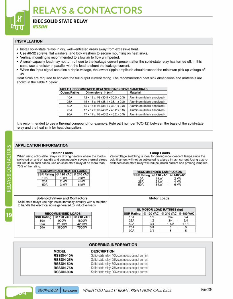
NEW!RELAYS & CONTACTORS
1154
NEW!RE
LAYS
& C
ONT
ACTO
RS
19
WHEN YOU NEED IT RIGHT, RIGHT NOW, CALL KELE.kele.com888-397-5353 USA March 2014
Zero-voltage switching is ideal for driving incandescent lamps since thecold fillament will not be subjected to a large inrush current. Using a zero-switched solid-state relay will reduce inrush current and prolong lamp life.
When using solid-state relays for driving heaters where the load isswitched on and off rapidly and continuously, severe thermal stresswill result. In such cases, use an solid-state relay at no more than75% of the rating.
RECOMMENDED HEATER LOADSSSR Rating @ 120 VAC @ 240 VAC
10A25A50A
1 kW2 kW3 kW
2 kW4 kW6 kW
Solid-state relays use high-noise immunity circuitry with a snubberto handle the electrical noise generated by inductive loads.
UL MOTOR LOAD RATINGS (hp)SSR Rating @ 120 VAC @ 240 VAC @ 480 VAC
10A25A50A75A90A
1/21/23/43/43/4
3/43/4
1-1/255
3/43/4
1-1/255
SSR Rating @ 120 VAC @ 240 VAC10A25A50A
900W2100W3800W
1800W4200W7500W
RECOMMENDED LOADS
SSR Rating @ 120 VAC @ 240 VAC10A25A50A
1 kW2 kW3 kW
2 kW4 kW6 kW
RECOMMENDED LAMP LOADS
Heater Loads Lamp Loads
Solenoid Valves and Contactors Motor Loads
IDEC SOLID STATE RELAYRSSDN
APPLICATION INFORMATION
INSTALLATION
ORDERING INFORMATION
MODEL DESCRIPTIONRSSDN-10A Solid-state relay, 10A continuous output currentRSSDN-25A Solid-state relay, 25A continuous output currentRSSDN-50A Solid-state relay, 50A continuous output currentRSSDN-75A Solid-state relay, 75A continuous output currentRSSDN-90A Solid-state relay, 90A continuous output current
• Install solid-state relays in dry, well-ventilated areas away from excessive heat .• Use #6-32 screws, flat washers, and lock washers to secure mounting on heat sinks .• Vertical mounting is recommended to allow air to flow unimpeded .• A small-capacity load may not turn off due to the leakage current present after the solid-state relay has turned off . In this
case, use a resistor in parallel with the load to shunt the leakage current .• When the input signal contains a ripple voltage, the lowest ripple amplitude should exceed the minimum pick-up voltage of
4V .Heat sinks are required to achieve the full output current rating . The recommended heat sink dimensions and materials are shown in the Table 1 below .
It is recommended to use a thermal compound (for example, Kele part number TCC-12) between the base of the solid-state relay and the heat sink for heat dissipation .
Output RatingTABLE 1. RECOMMENDED HEAT SINK DIMENSIONS / MATERIALS
Dimensions in (cm) Material
10A25A50A
75A90A
12 x 12 x 1/8 (30.5 x 30.5 x 0.3)15 x 15 x 1/8 (38.1 x 38.1 x 0.3) 15 x 15 x 1/8 (38.1 x 38.1 x 0.3)
17 x 17 x 1/8 (43.2 x 43.2 x 0.3)17 x 17 x 1/8 (43.2 x 43.2 x 0.3)
Aluminum (black anodized)Aluminum (black anodized)Aluminum (black anodized)
Aluminum (black anodized)Aluminum (black anodized)

NEW!
1155
RELAYS & CONTACTORSRELAYS & CO
NTACTORS
19
WE MAKE IT EASY. kele.com 888-397-5353 USAMarch 2014
SPECIAL VOLTAGE RELAYS20307 SERIES
Coil Rating 208 VAC @ 60 Hz, 277 VAC @ 60 Hz
Coil Power 2 .2 VARelay Type DPDT (2 form C)Contact Rating 13A, 1/3 hp @ 120 VAC;
13A, 1/2 hp @ 277 VAC; 3A, 3/4 hp @ 600 VAC; 10A @ 28 VDC NOTE: SR3B-05 socket is rated for 10A, 300 V max
Dimensions 2 .2"H x 1 .5"W x 1 .37"D (5 .6 x 3 .8 x 3 .5 cm)
Approvals UL recognized File #E7443Weight 0 .5 lb (0 .23 kg)Warranty 1 year
DESCRIPTIONThe 20307 Series plug-in style relays offer the flexibility of using 208 VAC or 277 VAC single-phase voltages for relay control . These relays are DPDT and plug into a standard three-pole general purpose relay socket .
FEATURES• 208 VAC and 277 VAC coils• 13A contact rating• UL recognized
1
4
7
A
(-)
3
6
9
B
(+)
Bottom View
WIRINGSPECIFICATIONS
ORDERING INFORMATION
MODEL DESCRIPTION20307-86 Relay, 208 VAC coil, DPDT20307-87 Relay, 277 VAC coil, DPDT
20307
SR3B-05• Socket mounting• Heavy-duty construction
ALTERNATING RELAYMODEL ALT
Supply Voltage 20-26 VAC/VDC, 95-125 VACSupply Current 40 mAContact Rating SPDT, 480 VA @ 240 VACControl Signal 115 VAC, 2 mA, 24 VAC/VDC, 2 mAOperating Temperature -4° to 122°F (-20° to 50°C)Debounce Time Delay 0 .5 secAprroval UL File E68520, CSAWeight 0 .35 lb (0 .16 Kg)Warranty 5 years
ORDERING INFORMATION
DESCRIPTION
The Model ALT alternating relay is commonly used to alternate between two loads to equalize run-time . When an external control switch opens, the Model ALT’s output contacts transfer from one state to the other . When an external control switch closes, the output contacts remain in their current state . The SW option offers an override potentiometer switch on top of the relay that allows manual override control of either load or automatic operation .
FEATURES
• Alternation between two loads to equalize run time • Two LEDs to indicate the energized load• Override switch• Debounce time delay
N.C.
N.O.C
Supply Voltage
ControlSwitch
Bottom View
1
8 654
32
7
24 VAC/VDCor 115 VAC
WIRING
MODEL DESCRIPTIONALT-115-S-SW Alternating relay, 115 VAC, override switchALT-24-S-SW Alternating relay, 24 VAC/VDC, override switch
SPECIFICATIONS
RELATED PRODUCTS PAGEOT08PC Octal Relay Socket for Model ALT
RELATED PRODUCTS PAGESR3B-05 Relay socket, three-pole blade type, DIN/surface mount 1123

NEW!RELAYS & CONTACTORS
1156
NEW!RE
LAYS
& C
ONT
ACTO
RS
19
WHEN YOU NEED IT RIGHT, RIGHT NOW, CALL KELE.kele.com888-397-5353 USA March 2014
DELAY ON MAKE / INTERVAL TIMERS438USA, 438USA-INT
Coil Rating 24-240 VAC (50/60 Hz), 19-288 VAC (50/60 Hz) or VDC
Leakage Current 438USA-INT Off State: 1 mA maximum @ 240V, 438USA Off State: 0 .6 mA @ 24V, 1 .8 mA
@ 48 V, 5 .4 mA @ 120V, 11 .4 mA @240 V
Output 10 mA to 1A inductive; inrush current to 25A for 8 ms
Range 1 to 1024 seconds, 1-second increments
Transient Protection 6000V for 8 .3 msVoltage Drop 4V maximum, ON stateAccuracy ±10% of setpointAdjustments 10-position DIP switch
Recycle Time 100 ms, 50 ms after timing cycle, 200 ms during timing cycleRepeatability ±1% nominalTiming Interval timer, Delay on make
(ON-Delay)Operating Temperature -4° to 185°F (-20° to 85°C)Storage Humidity 95% non-condensingApprovals UL-recognized component, File
#E47858; CSA certified, File #LR31931-3
Weight 0 .2 lb (0 .091 kg)Warranty 1 year
DESCRIPTIONThe Model 438USA universal switch-adjustable time capsule is an all solid state timer that provides delay on make (ON-Delay) control of a load device operating from 19-288 VAC/DC . The Model 438USA controls up to a 1A load, such as a relay or solenoid .
The Model 438USA-INT universal switch-adjustable time capsule is an all solid-state timer that provides interval timing control of a load device operating from 24 to 240 VAC . The 438USA-INT controls up to a 1A load, such as a relay or solenoid .
FEATURES• Encapsulated digital-timing circuitry• Switch-selectable delay• Low cost• Transient protected• 1A output rating
SPECIFICATIONS
438USA
438USA-INT
OPERATIONGeneralTiming is set via a binary-coded DIP switch and is adjustable from 1 to 1024 seconds . With all switches closed, there is an internal, one-second delay; with all switches open, there is a 1024-second delay time . Prior to applying power to the timer, set the switches to the correct position for the desired time .
438USA - Delay-on-Make (ON-Delay)When power is applied, the Model 438USA remains in the off state, allowing only leakage current to flow . Once the preset time period elapses, the unit switches on, allowing full current
to flow and the load to energize . The load remains energized as long as power is applied . When power is removed, the unit resets and is ready for another timing period .
438USA-INT - IntervalWhen voltage is applied, the Model 438USA-INT turns on, permitting full load current to flow . At the end of the preset timing period, the unit turns off and permits only leakage current to flow through the load . To recycle, the operating voltage must be removed and reapplied .

NEW!
1157
RELAYS & CONTACTORSRELAYS & CO
NTACTORS
19
WE MAKE IT EASY. kele.com 888-397-5353 USAMarch 2014
1 2 3 4 5 6 7 8 9 10
OPEN
1
51216
82
1
3216
82
1
+1*540 sec 60 sec
539+1*59
2 3 4 5 6 7 8 9 10
OPEN
To delay 540-second interval To delay 60-second interval
DELAY ON MAKE / INTERVAL TIMERS438USA, 438USA-INT
1 2 3 4 5 6 7 8 9 10
LOAD
19-288 VAC/VDCInput
Terminals0.25 Spade
1.7(4.31)
0.90(2.29)
0.27(.69)
0.20(0.51)
0.36(0.91)
2.25(5.71)
2.65(6.73)
Four Mounting Holes0.16 (0.41) dia
0.76(1.93)
in(cm)
438USA
TIME SETTINGS
DIMENSIONS / WIRING
ORDERING INFORMATION
MODEL DESCRIPTION438USA-INT Universal switch-adjustable time capsule, interval timer438USA Universal switch-adjustable time capsule, delay on make (ON-delay) timer
1 2 3 4 5 6 7 8 9 10
24 - 240 VAC LOAD*(yellow) (white)(black)(white)
0 .90(2 .29)
0 .20(0 .51)
2 .65(6 .731)
Four Mounting Holes0 .16 (0 .3962) dia
2 .25(5 .72)
0 .76(1 .93)
1 .7(4 .32)
Four 20 AWG wire (two for operatingvoltage and two for load circuit)
438USA-INT
* Do not apply voltage to load wires . The load is powered from the input
voltage .
Power
Load
Time Delay
FIGURE 1. TIMING
438USA
Power
Load
TimingInterval
438USA-INT

NEW!RELAYS & CONTACTORS
1158
NEW!RE
LAYS
& C
ONT
ACTO
RS
19
WHEN YOU NEED IT RIGHT, RIGHT NOW, CALL KELE.kele.com888-397-5353 USA March 2014
IDEC MULTIFUNCTION ELECTRONIC TIMERSRTE SERIES
Time Delay Settings 0 .1 sec to 600 hoursContact Configuration 2 Form C, DPDT (delay outputs)Load Type 10A resistive @ 240 VAC, 30 VDC;
7A inductive @ 240 VAC, 30 VDC; 1/6 hp @ 120 VAC; 1/3 hp @ 240 VAC
Input AD models 24 VAC/VDC (3 .5 VA/1 .7W) AF models 120VAC (6 .6 VA)Operating Temperature -4° to 149°F (-20° to 65°C)Operating Humidity 35% to 85% RHReset Time 100 ms maximumAccuracy ±0 .2%, ±20 msSetting Error ±10% maximumInsulation Resistance 100 MΩ minimum (500 VDC)Dielectric Strength Between power and output
terminals: 2000 VAC, 1 minute Between contacts of different poles:
2000 VAC, 1 minute Between contacts on the same
pole: 1000 VAC, 1 minuteElectrical Life 500,000 operations (resistive)Mechanical Life 50 million operationsWeight 0 .2 lb (0 .091 kg) Approvals UL listed, File #E66043, CEWarranty 1 year
RTE-P 8/11 Pin: A = 3 .06 (7 .79)RTE-B 11 Blade: A = 2 .95 (7 .49)
in(cm)
1 .57
(4 .0
)
1 .40(3 .6)
A
DESCRIPTIONThe RTE Series multi-function electronic timers are socket-mounted adjustable time delay relays available in two function groups . The timer functions and time ranges are easily selected by setting external switches . The knob on the front of the timer is used to set the precise delay period within the selected time range .
Timer FunctionsRTE-B1/RTE-P1 (Power-Triggered)-ON-Delay, Interval, OFF-Cycle, ON-CycleRTE-B2/RTE-P2 (Signal-triggered)-ON-Delay, OFF-Cycle, OFF-Delay, ON-Cycle, Single-Shot
FEATURES
• Selectable 10 timing functions and 20 time ranges• Time delay settings from 0.1 second to 600 hours• Two Form C delayed output contacts• Space-saving package • High repeat accuracy of ±0.2%• On and timing out LED indicators• Standard 8-pin, 11-pin, or 11-blade relay socket• UL Listed, CE certified
ControlSignal Switch Control
Signal Switch
Power(AC or DC)
Power(AC or DC)
3
4 5
6
7
3
45
67
8
9
10111
2
1
4
7
A
3
6
9
2
5
8
B81
2
1
4
7
A B
2
5
8
3
6
9
Delay DelayDelay Delay
RTE-B1/RTE-P1
Bottom View
Do not apply voltage Do not apply voltageto terminals 5 and 6 . to terminals 2 and 5 .
RTE-B2/RTE-P2
Delay DelayDelay Delay
Power(AC or DC)Power
(AC or DC)
WIRING
DIMENSIONS
SPECIFICATIONS
SR2P-06
RTE

NEW!
1159
RELAYS & CONTACTORSRELAYS & CO
NTACTORS
19
WE MAKE IT EASY. kele.com 888-397-5353 USAMarch 2014
ORDERING INFORMATION
IDEC MULTIFUNCTION ELECTRONIC TIMERSRTE SERIES
OPERATION
E: Signal OFF-Delay
C: Cycle 1 (power start, OFF first)
A: ON-Delay 1 (power start)
Set timer for desired delay, apply power to coil . First transfer of contacts occurs after preset delay has elapsed, after the next elapse of preset delay contacts return to original position . The timer now cycles between on and off as long as power is applied (duty ratio 1:1) .ITEM TERMINAL NO.
Power
DelayedContact
Indicator
Set Time
PWR
OUT
(1)1-4,5-8(2)1-7,3-9 (NC)
(1)1-3,6-8(2)4-7,6-9 (NO)
(1)2-7(2)A-B
OPERATION
TT
When a preset time has elapsed after the start input turned on while power is on, the NO output contact goes on .
RTE-P1, -B1
ITEM TERMINAL NO.
Power
DelayedContact
Indicator
Set Time
PWR
OUT
(A)1-4,8-11(B)1-7,3-9 (NC)
(A)1-3,9-11(B)4-7,6-9 (NO)
(A)2-10(B)A-B
OPERATION
Start(A)5-6(B)2-5
T
When the start input turns on while power is on, the NO contact goes on . The output oscillates at a preset cycle (duty ratio 1:1) .
ITEM TERMINAL NO.
Power
DelayedContact
Indicator
Set Time
PWR
OUT
(A)1-4,8-11(B)1-7,3-9 (NC)
(A)1-3,9-11(B)4-7,6-9 (NO)
(A)2-10(B)A-B
OPERATION
Start(A)5-6(B)2-5
T TaT T T T T T T
When power is turned on while the start input is on, the NO output contact goes on . When a preset time has elapsed after the start input turned off, the NO output contact goes off .ITEM TERMINAL NO.
Power
DelayedContact
Indicator
Set Time
PWR
OUT
(A)1-4,8-11(B)1-7,3-9 (NC)
(A)1-3,9-11(B)4-7,6-9 (NO)
(A)2-10(B)A-B
OPERATION
Start (A)5-6(B)2-5
T TaTa T
When the start input turns on while power is on, the NO output contact goes on . When a preset time has elapsed, the NO output contact goes off .
ITEM TERMINAL NO.
Power
DelayedContact
Indicator
Set Time
PWR
OUT
(A)1-4,8-11(B)1-7,3-9 (NC)
(A)1-3,9-11(B)4-7,6-9 (NO)
(A)2-10(B)A-B
OPERATION
Start(A)5-6(B)2-5
T Ta
Set timer for desired delay, apply power to coil . Contacts transfer after preset time has elapsed, and remain in transferred position until timer is reset . Reset occurs with removal of power .ITEM TERMINAL NO.
Power
DelayedContact
Indicator
Set Time
PWR
OUT
(1)1-4,5-8(2)1-7,3-9 (NC)
(1)1-3,6-8(2)4-7,6-9 (NO)
(1)2-7(2)A-B
OPERATION
T
Set timer for desired delay, apply power to coil . Contacts transfer immediately, and return to original position after preset time has elapsed . Reset occurs with removal of power .ITEM TERMINAL NO.
Power
DelayedContact
Indicator
Set Time
PWR
OUT
(1)1-4,5-8(2)1-7,3-9 (NC)
(1)1-3,6-8(2)4-7,6-9 (NO)
(1)2-7(2)A-B
OPERATION
T
Note: T = Set Time, Ta = Shorter than set time, (1): RTE-P1, (2): RTE-B1, (A): RTE-P2, (B): RTE-B2
Functions in same manner as Mode C, with the exception that first transfer of contacts occurs as soon as power is applied . The ratio is 1:1 . Time On = Time Off
ITEM TERMINAL NO.
Power
DelayedContact
Indicator
Set Time
PWR
OUT
(1)1-4,5-8(2)1-7,3-9 (NC)
(1)1-3,6-8(2)4-7,6-9 (NO)
(1)2-7(2)A-B
OPERATION
TT
RTE-P2, -B2
When the start input turns on while power is on, the output oscillates at a preset cycle (duty ratio 1:1), starting while the NO contact off .ITEM TERMINAL NO.
Power
DelayedContact
Indicator
Set Time
PWR
OUT
(A)1-4,8-11(B)1-7,3-9 (NC)
(A)1-3,9-11(B)4-7,6-9 (NO)
(A)2-10(B)A-B
OPERATION
Start (A)5-6(B)2-5
T TaT T T T T T T T
When the start input turns on while power is on, the NO output contact goes on . When a preset time has elapsed while the start input remains on, the output contact goes off . When the start input turns off, the NO contact goes on again . When a preset time has elapsed after the start input turned off, the NO contact goes off .
D: Signal ON/OFF-Delay
ITEM TERMINAL NO.
Power
DelayedContact
Indicator
Set Time
PWR
OUT
(A)1-4,8-11(B)1-7,3-9 (NC)
(A)1-3,9-11(B)4-7,6-9 (NO)
(A)2-10(B)A-B
OPERATION
Start(A)5-6(B)2-5
T TaT Ta T T
A: ON-Delay 2 (signal start)
C: Cycle 4 (signal start, ON first)
F: One-Shot (signal start)
B: Cycle 2 (signal start, OFF first)
B: Interval (power start)
D: Cycle 3 (power start, ON first)
MODEL DESCRIPTIONRTE-B1AD24 11 Blade 24 VAC/VDC On-delay, interval, off-cycle, on-cycle SR3B-05RTE-B1AF20 11 Blade 100-240 VAC On-delay, interval, off-cycle, on-cycle SR3B-05RTE-B2AD24 11 Blade 24 VAC/VDC On-delay, off-cycle, off-delay, on-cycle, single shot SR3B-05RTE-B2AF20 11 Blade 100-240 VAC On-delay, off-cycle, off-delay, on-cycle, single shot SR3B-05RTE-P1AD24 8 Pin 24 VAC/VDC On-delay, interval, off-cycle, on-cycle SR2P-06RTE-P1AF20 8 Pin 100-240 VAC On-delay, interval, off-cycle, on-cycle SR2P-06RTE-P2AD24 11 Pin 24 VAC/VDC On-delay, off-cycle, off-delay, on-cycle, single shot SR3P-06RTE-P2AF20 11 Pin 100-240 VAC On-delay, off-cycle, off-delay, on-cycle, single shot SR3P-06RTE-P1D12 8 pin 12 VDC On- Delay, interval, off-cycle, on-cycle SR3P-05CRTE-P2D12 11 pin 12 VDC On-delay, off-cycle, off-delay, on-cycle, single shot SR3P-05C
RELATED PRODUCTS PAGESR2P-06 Relay socket, DPDT pin type, DIN/surface mount 1123SR3B-05 Relay socket, three-pole blade type, DIN/surface mount 1123SR3P-05C Relay socket, SPDT, DPDT, or 3PDT blade type, DIN/surface mount 1123SR3P-06 Relay socket, 3PDT pin type, DIN/surface mount 1123

NEW!RELAYS & CONTACTORS
1160
NEW!RE
LAYS
& C
ONT
ACTO
RS
19
WHEN YOU NEED IT RIGHT, RIGHT NOW, CALL KELE.kele.com888-397-5353 USA March 2014
MULTIFUNCTION TIMING RELAYSTRU SERIES
Input Voltage 19 to 264 VAC and 19 to 30 VDCFrequency 50/60 HzOutput Type Electromechanical relayContact Configuration SPDT & DPDT, isolatedLoad Type 10A resistive @ 120/240 VAC, 28
VDC; 1/3 HP @ 120/240 VACElectrical Life 1 million operationsMechanical Life 10 million operations
Accuracy ±0 .1%Adjustments 4 position DIP switchOperating Temperature -4° to 149°F to (-20° to 65°C)Storage Temperature -22° to 185°F (-30° to 85°C)Mounting Plug-in socketApprovals CE, CSA, UR File #E57310Weight 0 .38 lb (0 .17kg)Warranty 10 years
DESCRIPTIONThe TRU Series is a multifunction, knob adjustable, universal time delay relay . It includes six of the most popular timing functions selected by a slide switch . The time delay is knob adjustable and the time delay range is switch selectable . The repeat accuracy is ± 0 .1% . Both function and time range can be selected on the top face of the unit . In addition to multifunctioning and multiple time ranges, the TRU Series features universal input voltage; 19 to 264VAC and 19 to 30VDC and full 10A output relay . The TRU Series can directly replace up to 1000 competitive time delay relay models .
FEATURES• Microcontroller ±0.1% repeat accuracy• Six timing functions are switch selectable• 0.1s - 1000m in six ranges
DIMENSIONS
SPECIFICATIONS
TRU Series
≤2.39(60.7)
≤1.78(45.2)
≤3.44 (87.3)
≤2.91 (73.9)

NEW!
1161
RELAYS & CONTACTORSRELAYS & CO
NTACTORS
19
WE MAKE IT EASY. kele.com 888-397-5353 USAMarch 2014
MULTIFUNCTION TIMING RELAYSTRU SERIES
ORDERING INFORMATION
WIRING
MODEL DESCRIPTIONTRU1 Multifunction tming relay, 24-240VAC, 24VDC, DPDT, adjustable 8 pin plug-inTRU2 Multifunction timing relay, 24-240VAC, 24VDC, SPDT, adjustable 8 pin plug-inTRU3 Multifunction timing relay, 24-240VAC, 24VDC, DPDT, adjustable 11 pin plug-in
L1 N/L2
Delay-on-Make
Interval
Recycling
8-pin DPDT
L1 N/L2
11-pin DPDT
S1 = Initiate Switch
L1 N/L2
Delay-on-Make
Interval
Single Shot
Recycling (ON Time First,
Equal Recycle Delays)
Delay-on-Break
Retriggerable Single Shot
8-pin SPDT
RELATED PRODUCTS NDS-11 11 pin socket base, 300VAC, surface or DIN mount NDS-8 8 pin socket base, 300VAC, surface or DIN mount
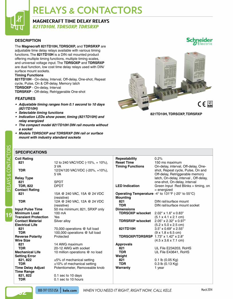
NEW!RELAYS & CONTACTORS
1162
NEW!RE
LAYS
& C
ONT
ACTO
RS
19
WHEN YOU NEED IT RIGHT, RIGHT NOW, CALL KELE.kele.com888-397-5353 USA March 2014
MAGNECRAFT TIME DELAY RELAYS821TD10H, TDRSOXP, TDRSRXP
Coil Rating 821 12 to 240 VAC/VDC (-15%, + 10%),
3 VA TDR 12/24/120 VAC/VDC (-20%, +10%),
5 VARelay Type 821 SPDT TDR, 822 DPDTContact Rating 821 15A @ 240 VAC, 15A @ 24 VDC
(resistive) TDR 12A @ 240 VAC, 12A @ 24 VDC
(resistive)Input Pulse Time 50 ms minimum; 821, SRXP onlyMinimum Load 100 mATransient Protection YesContact Material Silver alloyElectrical Life 821 70,000 operations @ full load TDR 100,000 operations @ full loadReverse Polarity ProtectedWire Size 821 14 AWG maximum TDR 20-12 AWG with socketMechanical Life 10 million operations @ no loadSetting Error 821, 822 ±5% of mechanical setting TDR ±10% of mechanical settingTime Delay Adjust Potentiometer, Removeable knobTime Range 821, 822 0 .1 sec to 10 days TDR 0 .1 sec to 10 hours
Repeatability 0 .2%Reset Time 150 ms maximumTiming Functions On-delay, interval, Off-delay, One-
shot, Repeat cycle, Pulse, On and Off-delay, Retriggerable memory latch, On-delay, interval , Off-delay, one-shot, On-delay, interval
LED Indication Green Input Red Blinks = timing, on = energized
Operating Temperature -4° to 131°F (-20° to 55°C)Mounting 821 DIN rail/surface mount TDR DIN rail/surface mount socketDimensions TDRSOXP w/socket 2 .02" x 1 .6" x 0 .83"
(5 .1 x 4 .1 x 2 .1 cm) TDRSRXP w/socket 2 .05" x 2 .32" x 0 .97"
(5 .2 x 5 .0 x 2 .5 cm) 821TD10H 3 .5" x 0 .69" x 2 .55"
(9 x 1 .8 x 6 .5 cm) TDRSOXP/TDRSRSP 1 .73" x 1 .42" x 2 .8"
(4 .5 x 3 .6 x 7 .1 cm)Approvals 821 UL File E234203, RoHS TDR UL File E43641, RoHSWeight 821 0 .1 lb (0 .05 Kg) TDR 0 .3 lb (0 .13 Kg)Warranty 1 year
DESCRIPTIONThe Magnecraft 821TD10H, TDRSOXP, and TDRSRXP are adjustable time delay relays available with various timing functions . The 821TD10H is a DIN rail mounted product offering multiple timing functions, multiple timing scales, and universal voltage input . The TDRSOXP and TDRSRXP are dual function, low cost time delay relays used with DIN/surface mount sockets .Timing Functions821TD10H - On-delay, Interval, Off-delay, One-shot, Repeat cycle, Pulse, On & Off-delay, Memory latchTDRSOXP - On-delay, IntervalTDRSRXP - Off-delay, Retriggerable One-shot
FEATURES• Adjustable timing ranges from 0.1 second to 10 days
(821TD10H)• Selectable timing functions• Indication LEDs show power, timing (821TD10H) and
relay energized• The compact model 821TD10H DIN rail mounts without
a socket• Models TDRSOXP and TDRSRXP DIN rail or surface
mount with industry standard sockets
SPECIFICATIONS
821TD10H, TDRSOXP, TDRSRXP

NEW!
1163
RELAYS & CONTACTORSRELAYS & CO
NTACTORS
19
WE MAKE IT EASY. kele.com 888-397-5353 USAMarch 2014
tP
ROn-Delay
821 Function: ATDRSOXP: SW1 OFF
R
POFF-Delay S break
821 Function: DTDRSRXP: SW1 OFF
tS
tP
RInterval
821 Function: CTDRSOXP: SW1 ON
t tt t
P
RRepeat Cycle: OFF First
821 Function: B
R
POn and Off Delay
S make/break821 Function: I
t tt t
S
R
PMemory Latch - S make
821 Function: J
S
P
RRepeat Cycle: ON First
821 Function: F
t tt
A1+ –
S A2
15 16 18
TimeAdjust
Multiplier
Red Timing/Output LED
Green InputLED
FunctionSelect
Time ScaleSelect
Time ScaleSelection
1 sec10 sec1 min
10 min1 hr
10 hr1 day
10 dayAlways ONAlways OFF
Time AdjustMultiplier
0.10.20.30.40.50.60.70.80.91.0
P - Power R - Relay Output S - Control Switch t - Time Delay
Time Range Digital Switch Position II III IV0.1sec-1sec OFF OFF OFF1sec-10sec OFF OFF ON10sec-100sec OFF ON OFF0.1min-1min OFF ON ON1min-10min ON OFF OFF10min-100min ON OFF ON0.1hr-1hr ON ON OFF1hr-10hr ON ON ON
TDRSOXP/TDRSRXPTime Range Selection
TDRSOXPTDRSRXP
821TD10H
GreenInputLED
Digital Switches
Fine Adjust Knob
RedRelayLED
OnOutput
I II III IV
off on
FunctionTimeTimeTime
Pulse Pulset
P
RPulse (0.5 sec)821 Function: G
t
1234 5 6 7
89
10
R
POne-Shot - S make
821 Function: HTDRSRXP: SW1 ON*
tS *
* Retriggerable: time delay period restarts any time the control switch is opened and closed.
S
RRetriggerable One Shot
821 Function: E
tP
t t
MAGNECRAFT TIME DELAY RELAYS821TD10H, TDRSOXP, TDRSRXP
Control switch ignoredfunctions “A” to “E”
Control switch requiredfunctions “F” to “J”
12-240V Power (AC or DC)CONTROLSWITCH
A1+ –
S A2
15 16 18COM NC NO
821TD10HTDRSRXPTDRSOXP
24 or 120VPower
(AC or DC)Non-polarity Sensitive
81
54
2 7
3 6
24 or 120VPower
(AC or DC)Non-polarity Sensitive
Use shielded wire for external trigger.Dry switch only.
Use shielded wire for external trigger.Dry switch only.
1 112 10
3 94 8
5 76
ExternalControlSwitch + –
WIRING
ORDERING INFORMATION
OPERATION
MODEL DESCRIPTION821TD10H-UNI Time-delay relay, SPDT, multifunction, 12-240 VAC/VDC, 0.1 sec to 10 daysTDRSOXP-120 Time-delay relay, on-delay/interval, 120 VAC/VDC, 0.1 sec to 10 hoursTDRSOXP-24 Time-delay relay, on-delay/interval, 24 VAC/VDC, 0.1 sec to 10 hoursTDRSRXP-120 Time-delay relay, off-delay/single-shot, 120 VAC/VDC, 0.1 sec to 10 hoursTDRSRXP-24 Time-delay relay, off-delay/single-shot, 24 VAC/VDC, 0.1 sec to 10 hours70-464-1 Relay socket, eight-pin, use with TDRSOXP time delay relay70-465-1 Relay socket, 11-pin, use with TDRSRXP time delay relay

NEW!RELAYS & CONTACTORS
1164
NEW!RE
LAYS
& C
ONT
ACTO
RS
19
WHEN YOU NEED IT RIGHT, RIGHT NOW, CALL KELE.kele.com888-397-5353 USA March 2014
DELAY-ON-MAKE TIMING RELAYSTMV8000, KRDM
Operating Temperature TMV8000 -4° to 158°F (-20° to 70°C) KRPS -40° to 140°F (-40° to 60°C) KRDM -4° to 140°F (-20° to 60°C)Storage Temperature TMV8000 -22° to 185°F (-30° to 85°C) KRPS/KRDM -40° to 185°F (-40° to 85°C)
Operating Humidity 95% RH non-condensingPower Consumption ≤ 2VA for AC; ≤ 2W for DCMounting Surface mount with one #10 screwDimensions 2"W x 2"H x 1 .21"D
(5 .08 x 5 .08 x 3 .07 cm) Approvals CE, CSA, UR File #E57310Warranty 10 years
ORDERING INFORMATION
DESCRIPTIONThese Delay-on-Make timers cover all the popular voltages and time delays . These are a cost effective approach for applications that require small size, isolation, reliability and long life . Encapsulation protects against shock, vibration and humidity .
L1 N/L2
L1 N/L2
A knob is supplied for adjustable units, or RT terminals 4 & 5 for external adjust. See external adjustment vs. time delay chart. The untimed load is optional. S1 is not used for some functions.
V = Voltage C = Common, Transfer ContactNC = Normally Closed NO = Normally Open S1 = Initiate Switch UTL = Untimed Load
Load may be connected to terminal 3 or 1. TMV8000 has knob adjustment.
V = Voltage C = Common, Transfer ContactNO = Normally Open NC = Normally Closed
A knob is supplied for adjustable units, or RT terminals 4 & 5 for external adjust. See external adjustment vs time delay chart. Relay contacts are isolated.
L1 N/L2
WIRING
SPECIFICATIONS
TMV8000
TMV8000
KRPSA2M
KRPS Series
KRDM421
KRDM Series
SPECIFICATIONS TMV8000 KRPSA24M KRDM221* / KRDM421**
Supply Voltage 24-240 VAC/DC, 50/60 Hz 24-240 VAC/DC, 50/60 Hz 24 VAC/DC* / 120 VAC**, 50/60 Hz
Output Type Solid State Isolated Relay Contacts Isolated Relay Contacts
Output Form NO, open during timing SPDT SPDT
Output Rating (@ 40°C) 1A steady state, 10A inrush @ 55°C 10A @ 125VAC; 5A @ 230VAC; 1/4 hp @ 125VAC
10A @ 125VAC; 5A @ 230VAC & 28VDC; 1/4 hp @ 125VAC
Timing Range 0.1 to 8 min adjustable 0.1 to 10 min adjustable 1 - 100 seconds adjustable
Repeat Accuracy ±2% ±0.5% or 20ms, whichever is greater ±0.5% or 20ms, whichever is greater
Timing Tolerance ≤ ± 10% ≤ ± 2% ≤ ± 5%
Reset Time ≤ 100ms ≤ 150ms ≤ 150ms
Circuitry Protection Encapsultated Encapsultated Encapsultated
Isolation Voltage - ≥ 1500V RMS input to output ≥ 1500V RMS input to output
Insulation Resistance ≥ 100 M Ω ≥ 100 M Ω ≥ 100 M Ω
Termination .25 in. (6.35mm) male quick connect terminals
.25 in. (6.35mm) male quick connect terminals
.25 in. (6.35mm) male quick connect terminals
Weight 0.15 lb (0.07kg) 0.16 lb (0.08kg) 0.16 lb (0.08kg)
FEATURES
• Onboard adjust time delay• Compact 2" x 2" size• Adjustable timing ranges

NEW!
1165
RELAYS & CONTACTORSRELAYS & CO
NTACTORS
19
WE MAKE IT EASY. kele.com 888-397-5353 USAMarch 2014
ORDERING INFORMATIONSPECIFICATIONS CT1S30 T2D120A15M TA24A3 / TA24A5
Function DOM & DOB Lockout Lockout
Supply Voltage 24 VAC 24 VAC or 120/230 VAC in 2 ranges 12 or 24 VDC, 24 VAC
Output Type Solid State Solid State Solid State
Output Form NO NO NO
Output Rating 0.75A steady state, 5A inrush @ 55°C 1A steady state, 10A inrush @ 60°C 75mA, 1A @ 60°C
Timing Range 1 to 600s - -
Lockout Time - 1s - 100m in 4 adjustable ranges or fixed fixed 0.5, 1, 2, 3, or 5m
Repeat Accuracy ± 5% ± 1% or 20ms, whichever is greater -
Timing Tolerance ± 20% ± 30% -15% to 35%
Circuitry Protection Encapsultated Encapsultated Encapsultated
Anticipator Resistor ≥ 3000 Ω ≥ 3000 Ω ≥ 1800 Ω
Insulation Resistance ≥ 100 MΩ ≥ 100 MΩ ≥ 100 MΩ
Voltage Drop ˜= 1.25V ˜= 2.5V @ 1A ˜= 1.25V
Weight 0.15lb (0.07kg) 0.15lb (0.07kg) 0.15lb (0.07kg)
LOCKOUT DELAY TIMERTA, CT SERIES
Operating Temperature TA / CT Series -40° to 140°F (-40° to 60°C) T2D Series -4° to 140°F (-20° to 60°C)Storage Temperature -40° to 185°F (-40° to 85°C)Operating Humidity 95% RH non-condensingTerminations 0 .25 in . (6 .35 mm) male quick
connect terminalsMounting Surface mount with one #10 screwDimensions 2"W x 2"H x 1 .21"D
(5 .08 x 5 .08 x 3 .07cm)Approvals CE, CSA, UR File #E57310Warranty 10 years
DESCRIPTIONThe TA Series prevents rapid recycling of a compressor . A lockout delay is started when the thermostat opens, or input voltage is lost . Eliminates tripped circuit breakers or blown fuses caused by a locked rotor during short cycling . The TA will not allow the compressor to start when the line voltage is low . Because of the fast initiate time, bounce of the thermostat will not be transmitted to the compressor relay coil . A 30 second delay provides anti-reversing protection for scroll compressors . The CT Series combines a delay-on-make and delay-on-break time delay into one unit and may be used to control fan delays in heating and/or cooling equipment .
FEATURES• Lockout delay prevents rapid recycling of compressor• Low voltage brownout protection• Circuitry to activate the cooling anticipator (24VAC models)
L1 N
1Random Start Plus Lockout
L1 N
S1 = Initiate Switch, Contact, or Thermostat
CR = Compressor Relay (Load)
CA = Optional Cooling Anticipator
V = Voltage
L1 N/L2
V = Voltage L = LoadS1 = Initiate Switch or Thermostat
CR = Compressor Relay THMS = Wall Thermostat
WIRING
SPECIFICATIONS
CT1S30
CT1S30
T2D120A15M
T2D120A15M
TA24A3
TA24A3
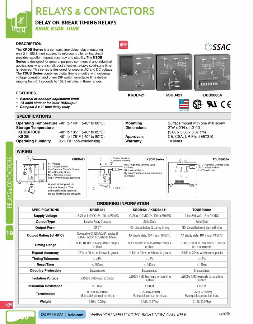
NEW!RELAYS & CONTACTORS
1166
NEW!RE
LAYS
& C
ONT
ACTO
RS
19
WHEN YOU NEED IT RIGHT, RIGHT NOW, CALL KELE.kele.com888-397-5353 USA March 2014
DELAY-ON-BREAK TIMING RELAYSKRDB, KSDB, TDUB
Operating Temperature -40° to 140°F (-40° to 60°C)Storage Temperature KRDB/TDUB -40° to 185°F (-40° to 85°C) KSDB -40° to 176°F (-40° to 80°C)Operating Humidity 95% RH non-condensing
Mounting Surface mount with one #10 screwDimensions 2"W x 2"H x 1 .21"D
(5 .08 x 5 .08 x 3 .07 cm)Approvals CE, CSA, UR File #E57310Warranty 10 years
ORDERING INFORMATION
DESCRIPTION
The KRDB Series is a compact time delay relay measuring only 2 in . (50 .8 mm) square . Its microcontroller timing circuit provides excellent repeat accuracy and stability . The KSDB Series is designed for general purpose commercial and industrial applications where a small, cost effective, reliable solid-state timer is required . This series is designed for popular AC and DC voltage . The TDUB Series combines digital timing circuitry with universal voltage operation and offers DIP switch selectable time delays ranging from 0 .1 seconds to 102 .3 minutes in three ranges .
FEATURES
• External or onboard adjustment knob• 1A solid state or Isolated 10Aoutput• Compact 2 x 2" time delay relay
WIRING
SPECIFICATIONS
KRDB421 KSDB421 TDUB3000A
L1 N/L2
UTL = Optional Untimed Load S1 = Initiate SwitchL = Timed Load
L1 N/L2
(Positive Switching)(Negative Switching)
UTL = Optional Untimed Load L = LoadS1 = Initiate SwitchRT is used when external adjustment is ordered.
L1 N/L2
.
V = Voltage S1 = Initiate Switch C = Common, Transfer Contact NO = Normally Open NC = Normally Closed UTL = Untimed Load (optional)
A knob is supplied for adjustable units. The untimed load is optional. Relay contacts are isolated.
KRDB421 KSDB Series TDUB3000A
SPECIFICATIONS KRDB421 KSDB421 / KSDB431* TDUB3000A
Supply Voltage 12, 24, or 110 VDC; 24, 120, or 230 VAC 12, 24, or 110 VDC; 24, 120, or 230 VAC 24 to 240 VAC, 12 to 24 VDC
Output Type Isolated Relay Contacts Solid State Solid State
Output Form SPDT NO, closed before & during timing NO, closed before & during timing
Output Rating (@ 40°C) 10A resistive @ 125VAC; 5A resistive @ 230VAC & 28VDC; 1/4 hp @ 125VAC 1A steady state, 10A inrush @ 60°C 1A steady state, 10A inrush @ 60°C
Timing Range 0.1s-1000m in 6 adjustable ranges or fixed
0.1s-1000m in 6 adjustable ranges or fixed
0.1-102.3s in 0.1s increments; 1-1023s in 1s increments
Repeat Accuracy ±0.5% or 20ms, whichever is greater ±0.5% or 20ms, whichever is greater ±0.5% or 20ms, whichever is greater
Timing Tolerance ≤ ±5% ≤ ±5% ≤ ±5%
Reset Time ≤ 150ms ≤ 150ms ≤ 150ms
Circuitry Protection Encapsulated Encapsulated Encapsulated
Isolation Voltage ≥1500V RMS input to output ≥2000V RMS terminals to mounting surface
≥2000V RMS terminals to mounting surface
Insulation Resistance ≥100 MΩ ≥100 MΩ ≥100 MΩ
Termination 0.25 in (6.35mm)Male quick connect terminals
0.25 in (6.35mm)Male quick connect terminals
0.25 in (6.35mm)Male quick connect terminals
Weight 0.16lb (0.08kg) 0.15lb (0.07kg) 0.15lb (0.07kg)

NEW!
1167
RELAYS & CONTACTORSRELAYS & CO
NTACTORS
19
WE MAKE IT EASY. kele.com 888-397-5353 USAMarch 2014
Supply Voltage 24 VAC/VDC @ 50 mAInput SPST switch or relayOutput One N .O . contact rated 120 VAC,
5A; one N .C . contact rated 120 VAC, 5A
Output Pulse Time 300 ms (contact Kele for special pulse time requiements, 5 sec maximum)
Weight 0 .25 lb (0 .11 kg)Warranty 18 months
ORDERING INFORMATION
KELE MOTOR STARTER INTERFACEPIL-2
Latch (start)Local start (push button)
+–
24 VAC/VDC
Commandcontact M
Local stop(push button)
Starter hold-in contact
L2L1
Unlatch(stop)
Power
Power
Command
PIL-2PULSE OUT
UL L
CMD INOFF ON
CMDIN
UL LPUP
Starter coil
3(7.62)
2.25(5.72)
PWR+
PWR–
LED IndicationPULSE OUT - UL ON only during unlatch (stop) pulsePULSE OUT - L ON only during latch (start) pulseCMD IN - OFF ON only when command contact is openCMD IN - ON ON only when command contact is closed
Power-upjumper
(shown in PUPposition)
in(cm)
DESCRIPTIONThe PIL-2 is designed to provide momentary contact closures to control motor starters with momentary start/stop push buttons . The PIL-2 acts as a remote start/stop station using a single maintained contact from a controller, switch, or relay .
FEATURES• LED indicators: Pulse out: latch/unlatch, Command
in: off/on• 24 VAC/DC power• Selectable power-up state (PUP)• Snap-track mounting for easy installation
MODEL DESCRIPTIONPIL-2 Motor starter interface, 300 ms pulsePIL-2-C Motor starter interface, special pulse (specify when ordering)
OPERATIONThe Model PIL-2 is operated by a single maintained N .C . or N .O . contact from a switch, relay, or controller . Closing the input contact causes the N .O . latch output to close momentarily for 300 ms to start a motor . Opening the input contact causes the N .C . unlatch output to open momentarily for 300 ms to stop a motor . A power-up feature allows the selection of either an immediate pulse out (PUP position), based on the current state of the input contact, or a pulse out only when the input contact changes state . LEDs indicate input state and output latch or unlatch pulses .
DIMENSIONS
SPECIFICATIONS
PIL-2

NEW!RELAYS & CONTACTORS
1168
NEW!RE
LAYS
& C
ONT
ACTO
RS
19
WHEN YOU NEED IT RIGHT, RIGHT NOW, CALL KELE.kele.com888-397-5353 USA March 2014
MOTOR LOAD SIZING
A resistive load is one that offers simple resistance to the flow of current . An example would be an electric heater .
An inductive load would be found in a motor, transformer, solenoid, or other device that has magnetizing coils . Inductive loads are often rated in amps with a separate motor rating in horsepower . They are characterized by high inrush current when contacts close, and by resistance to the stopping of current flow when contacts open (arcing) .
A pilot duty load is another specific type of inductive load that often has a separate rating . Pilot duty ratings come into play when relay contacts control the coils of other relays or contactors .
A lighting load can be ballast type (fluorescent and HID lighting) or tungsten (incandescent) . Ballasts are somewhat inductive, particularly the non-electronic types . Tungsten lighting presents a very low resistance at start-up (high starting current) when the filaments are cold, but behaves like a resistive load once the lamps are bright and hot . Tungsten loads can be the most destructive of all to a relay’s contacts unless they are specifically designed to handle such an inrush .
FULL LOAD CURRENT (AMPS) VS HPTHREE PHASE SINGLE PHASE
Volts 115V 230V 460V 115V 230VHP1/6 4.4 2.21/4 5.8 2.91/3 7.2 3.61/2 4 2 1 9.8 4.93/4 5.6 2.8 1.4 13.8 6.91 7.2 3.6 1.8 16 81-1/2 10.4 5.2 2.6 20 102 13.6 6.8 3.4 24 125 15.2 7.6 56 287-1/2 22 11 80 4010 28 14 100 5015 38 1920 52 2625 64 3230 77 3940 101 51
MOTOR LOAD SIZING
Recommended


![ME GSX600inwoo.kr/down/pro02/03/gsx600uk_5.pdf · 2019. 9. 11. · Rated current [A] 2.5 4.0 7.0 10.0 Overload capacity! 150% of rated current for 1 min Rated frequency! 50, 60 Hz](https://img.dokumen.tips/doc/110x75/612392559b50694d534e14dd/me-2019-9-11-rated-current-a-25-40-70-100-overload-capacity-150-of.jpg)


