RP18S
RELATIONSHIPS BETWEEN ROCKWELL AND BRINELLNUMBERS *
By S. N. Petrenko
ABSTRACT
Comparative Rockwell and Brinell tests were made on a great variety of ferrous
and nonferrous metals.Relationships between Brinell and Rockwell numbers, based on certain
simplifying assumptions, are:
_ . ,. ,constant
Brinell number
=
13o_Rockwell ball numberand
„ . „ ,constant
Brinell number=;(100—Rockwell cone number) 2
These equations were used as guides in finding empirical formulas which fitted
most closely the values determined experimentally. Of all the experimentalvalues obtained in this investigation very few differed by more than 10 per centfrom values obtained from these empirical equations.
Empirical equations were also found giving the tensile strengths of steels in
terms of their Rockwell numbers. Experimental values checked these equationswithin an error of plus or minus 15 per cent.
CONTENTS page
I. Introduction 19II. Purpose of investigation 20
III. Acknowledgments 20IV. Apparatus and procedure 20V. Theoretical considerations 22
VI. Experimental data 28VI I
.
Correlation of approximate theory and experiment 38VIII. Accuracy of empirical conversion formulas 42IX. Relationship of Rockwell numbers to tensile strength 44X. Results of earlier investigators 47XI
.
Summary 48
I. INTRODUCTION
Indentation hardness tests are growing in importance as a means of
checking the uniformity of the mechanical properties of metals usedin engineering structures and machines.
If a metal is of uniform composition and the process of its manufac-ture is reasonably well controlled, uniform indentation numbers are
nearly always a sufficient guarantee of its uniform quality. It is also
found that the tensile strength of steel can be estimated from its
Brinell number with sufficient accuracy for many commercialpurposes.The indentation test is preferred to a tensile test for control purposes
because it is nondestructive and relatively inexpensive and because
1 This paper supersedes a paper (B. S. Tech. Paper No. 334) with the same title and by the same author,published in 1927. The present paper includes the data (Tables 2 and 3) of the earlier paper, and, in addi-tion, the results of many more tests on various heat-treated steels (Table 2 (a)),
19

20 Bureau of Standards Journal of Research [vols
it can be applied to pieces of the regular factory output. Since anindentation very seldom impairs the usefulness of a tested piece, it
is in many cases not only possible but also practicable to test everypiece produced.
Brinell and Rockwell hardness tests are two of the various indenta-
tion tests which are being widely used for control purposes, and situa-
tions often arise in which a Brinell (or Rockwell) number is neededwhen only a Rockwell (or Brinell) number can be obtained. In suchcases a reliable chart or formula expressing a definite relationship
between Rockwell and Brinell numbers is of great practical value.
II. PURPOSE OF INVESTIGATION
The purpose of this investigation was:1. To make tests on a great number of the metals used in en-
gineering construction and thus obtain data sufficient for determiningthe relation between Rockwell and Brinell numbers and also the
relation between Rockwell numbers and tensile strength.
2. To determine the limits of error within which one of these num-bers may be used to estimate the other number and the tensile
strength of the material.
III. ACKNOWLEDGMENTS
The materials used in this investigation were contributed by thefollowing manufacturers: Aluminum Co. of America, AmericanMagnesium Corporation, Raritan Copper Works, Chase Metal Works,American Brass Co., Riverside Metal Works, International NickelCo., Union Drawn Steel Co., Colonial Steel Co., American RollingMills Co., Central Alloy Steel Co., Halcomb Steel Co., Firth Sterling
Steel Co., Carpenter Steel Co., and Wilson-Maeulen Co.The metallurgical division of this bureau contributed data on
Rockwell and Brinell numbers and tensile strengths for a greatvariety of steels.
2 (See Table 5.) These data made it possible to
get a more conclusive check on the errors involved in the use of theconversion formulas.
Credit is due Dr. L. B. Tuckerman 3 for his many valuable sugges-tions. Prof. G. F. Rouse made the study of the diamond tool andedited the manuscript.
IV. APPARATUS AND PROCEDURE
The Brinell machine used in this investigation (see fig. 1) is providedwith a dead-weight relief valve for maintaining the desired load onthe indenting tool. This consists of a spherical piston accuratelyfitted, without packing, to a cylinder connected with the pressurechamber. This piston carries a crossbar, A, and weights, B. Themaximum pressure is determined by the weights which are lifted by
* See Report in Trans, of A. S. M. E., 48, p. 533; 1926; entitled "Rough Turning With Particular Ref-erence to the Steel Cut," by H. J. French and T. O. Digges. The Rockwell and Brinell numbers forhard steels were obtained on samples (Table 5, samples I-9D to I-16B) used by Dr. Gillett, chief, metal-lurgical division, Bureau of Standards, in his work on molybdenum and cerium steels. The composition,heat treatment, and other data for these steels will be found in the book, Molybdenum, Cerium, and Re-lated Alloy Steels, by H. W. Gillett and E. L. Mack; 1925.
3 Principal scientist, mechanics and sound division, Bureau of Standards.

B. S. Journal of Research, RP185
Figure 1.
—
Brinell and Rockwell machines

Petrenko] Rockwell-Brinell Relationships 21
the piston as soon as this pressure is reached. The load remainsconstant as long as the piston floats.
A standard load of 3,000 kg was used in this investigation on metalshaving a Brinell number equal to or greater than 70, and a load of
500 kg was used on metals with a Brinell number less than 70. Inevery case the load was applied for 30 seconds. A Hultgren work-hardened steel ball, 10 mm in diameter, was used as the indentingtool.
The diameter of each indentation was measured with a Brinell
microscope having 0.1 mm graduations. Readings were estimatedto 0.01 mm.The Brinell number was obtained directly from a table 4 which
gives Brinell numbers corresponding to diameters of indentation.The Rockwell machine shown in Figure 1 has a dead-weight loading
device consisting of a double lever, A, having a total multiplicationratio of about 119. Materials listed in Table 2 were tested in this
machine. A newer model having only one lever was used for testing
the steels listed in Table 3. This machine was checked on the stand-ard blocks used for the older model and all readings fell within limits
of plus or minus 5 per cent of depth of indentation.
The specimen was placed on the table of the elevating screw, G(fig. 1), and was pressed against the indenting tool until a so-called
minor load of 10 kg was acting. Next, the pointer on the indicating
dial B was set at zero, after which the load was gradually increasedto a maximum value, designated the major load. The load was thenreduced to 10 kg and the Rockwell number was read from the dial.
The manufacturer recommends the following tools and loads for the
Rockwell machine: A steel ball He inch (1.588 mm) in diameter witha 100 kg major load, on soft and medium materials; a steel ball % inch(3.176 mm) in diameter with a 100 kg major load, on very soft
materials; and a diamond tool with a 150 kg major load on hardmaterials. This diamond tool, commonly called a cone, has anincluded angle of 120° and an apex lapped to a spherical surface. Thetool is patented by the manufacturer, and has the trade name "brale."Other major loads of 100 kg and 60 kg were used with the brale and60 kg with the Xe-inch ball in order to obtain more complete data onthe change of Rockwell numbers with change of load or indentingtool.
The direct reading dial B is provided with so-called "B" and "C"scales. The Rockwell ball number, designated in this paper by RB , is
read directly from the "B" scale. The cone number, designated in
this paper by Rc , is read directly from the "C " scale. The calibration
of the scales is such that the depth of indentation in mm, in excess of
that produced by the minor load, is (130 —RB)X 0.002 for the ball
and (100-RC)X 0.002 for the cone.There is no recognized standard for time under load in Rockwell
testing. In this investigation the major load was removed approxi-mately three-fourths second after it reached its maximum value.
Tests were made on six specimens to determine the change occurringin a Rockwell number due to a variation of time under load. Theresults are shown graphically in Figure 2. The greatest variation in
average Rockwell number over a 10-second period, a decrease of 0.8
* Miscellaneous Publication of the Bureau of Standards, No. 62.

22 Bureau of Standards Journal of Research [Vol. 6
point, was found in the case of steel block C 24-25. The averagedecrease in Rockwell number, 0.3 of a point, is less than the difference
usually found between individual readings on the same specimen.
V. THEORETICAL CONSIDERATIONS
Some symbols used in this discussion are:
Symbol Meaning
BnnRjBT,
kRc
Brinell number.Rockwell ball number, obtained using a major load of n kg and a ball with a diameter of m
inches.Rockwell cone number, obtained using a major load of k kg and the brale.
Dr. J. A. Brinell, a Swedish engineer,5 denned the indentationP
number which now bears his name as the ratio -p P being the load on
h~°"^;
^__^-
5tee/(:62S- 63.S)
''s^
^„.^^^ --_.
Steel(C24-25)
- Brass (L?«30-A )-
h-- H
71'me under had -seconds
Figure 2.
—
Effect of time under load upon Rockwellnumber
Circles represent average values obtained from five indentations.Dash lines show extreme variations. Values for zero time wereobtained within one-half second of the instant the major loadreached its maximum value. Identification marks on the stand-ard blocks are given in parentheses.
the indenting tool in kilograms and A the surface area of the indenta-tion in square millimeters.The Rockwell indentation number is defined as a constant minus
the depth of indentation. The constant and the depth are expressedin arbitrarily selected units.
Investigation has shown that the Brinell number, as defined above,is not a constant of the test material; that is, that the area of anindentation is not directly proportional to the load. Many of the
Congres International des Methodes d'Essai des Materiaux de Construction, 2, p. 83; 1901.

petrenko] Rockwell-Brinell Relationships 23
causes for this lack of proportionality can be given in a general way,P
but an exact theoretical discussion which involves the ratio -7 and
which takes into account all disturbing factors can not be given.
When it is impossible to carry out an exact deduction of a formularelating to quantities, one may resort to experiment and establish a
purely empirical formula. Unfortunately, unless there is a great massof well-distributed data, the purely empirical formula is, at best, often
unsatisfactory. Whenever it is possible to make assumptions whichare approximately true and which simplify the problem so that anapproximate formula can be derived, there is an obvious advantage in
carrying out the derivation because the resulting approximateformula is a valuable guide in rinding the most satisfactory empirical
formula.
In the present problem the simplifying assumption is Brineirsoriginal assumption that the area of an indentation is always directly
proportional to the load. Using this, it is possible to derive approxi-
mate formulas for converting Rockwell numbers into Brinell numbersor vice versa.
Applying the definition of the Brinell number to the Rockwell ball
test:
„ major load P . .
surface area of indentation 2irrH ^ '
where P is the major load, r the radius of the indenting ball, andH thetotal depth of indentation. Let the depth of indentation due to theminor load only be denoted by hq and let h = (H— h ) . Then, assumingthat the area of indentation is directly proportional to the load,
H P u iP
Fo=io
ori7=/^io
H=h P-10But h = (130- BB ) X 0.002
PE= (130-RB)X 0.002 Xpzrxo
Substituting kfequation (1)
R P-10 , .^7l~27rr(130-EB)X 0.002 W
Equation (2) can be written:
where
^=(130-^) (3)
n- p~ 10 u\° 27rr- (0.002) w

24 Bureau of Standards Journal of Research [Vol.5
The value of C corresponding to any particular Rockwell ball test
is easily found. For instance, considering the loo-SWe case, in which
a ball K 6 inch in diameter is used with a major load of 100 kg
90
2tt • (0.794) • 0.002
9,020
= 9,020
Bn=130—100^81216
Values of C corresponding to the other Rockwell ball tests have
been calculated, and all equations are shown in Table 1.
Assuming that the brale is a true cone and applying the definition
of the Brinell number to it
:
Bnmajor load
surface area of indentation tv tan 8 sec OH2
where P is major load, H the total depth of indentation, and 6 one-half
the angle of the cone.
Table 1.
—
Approximate relationships between Brinell and Rockwell numbers based
on the assumption that area of indentation is directly proportional to load
RockwellTheoretical relationship
Tool Load
Ball, 1/16 inch (1.588 mm) diameter
Ball, 1/8 inch (3.176 mm) diameter
Ball, 1/16 inch (1.588 mm) diameter
Brale, diamond, true cone having a 120°
angle.
Do
kg100
100
60
150
100
60
1 150
Bn9
'020
130— iooRbi/16
Bn 4 ' 510
130— ioo-Rsi/8
Bn- 5,01°
130— 60-Rfli/u
1,896,000
(100-i5oi?) Jc
1,074,000
Do
"n(100-ioo-Rc) 3
483,000
(lOO-eo-Rc) 3
Case I • • • For mRc greater than (100-466.7 S).
1,492.9Bn~S (100-mRc)
Case II • • • For noRc greater than (100-2,953 S) andless than (100-466.7 5).
150
Brale, diamond, the apex being a spher-ical segment of altitude S, angle of
conical portion 120°. (See fig. 3.)
•B""46.89SH-10.882 (Z,'+4.308SL)
L is obtained in terms of iso-Rc and S from:
LH-(4.308S)L+4.308S (S-15fto)=0
and
(100-iso.Rc) X0.002 = L+S-ho.
Case III • • • For 150-Rc less than (100-2,953 S).
150"Bn=
46.89 S2+10.882(L J+4.308SL)
L is obtained in terms of uoRc and S from£>+(4.308S)Z,-[60.325SH-15(dH-4.308Sd)]=0
and
(100-i5oi?c)X0.002 = X-d.
IOO-Rfll/19
ioo-Rbi/i«
ioo-Rc=1
=2Xiooi?Bi/8-130
= 1.800X«o.Rbi/i8-104
491 Xco-Rc- 49.1
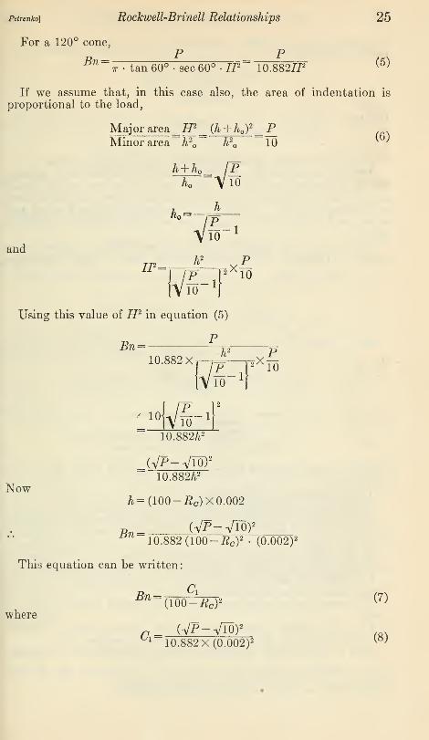
Petrenko] Rockwell-Brinell Relationships 25
For a 120° cone,
P PBn==
ir> tan 60°. sec 60° -H1= 10.882#2 (5)
If we assume that, in this case also, the area of indentation is
proportional to the load,
Major area=#2
^ (h + h )2
= PMinor area h 2
Q h2 10
h±hK IP
k =
andv5-'h 2 PP |
2X10
16uUsing this value of H2 in equation (5)
PBn
h 2 P10.882Xr-7= r2^~
Now
10.882/i2
^(VP-ViO)2
10.882/t2
/i=(100-#c)X 0.002
Bn = (Vp-Viov10.882 (100-Rc )
2• (0.002) 2
This equation can be written:
where
° l10.882 X(0.002) 2
(6)
Bn={100°-Rc)*
<*>
(8)

26 Bureau of Standards Journal of Research [Vol. 6
Considering the i50Rc case, in which the major load is 150 kg,
(Vi5o-Vio) 2
a=
and
Bn=
10.882 X(0.002) 2
= 1,896,000
1,896,000
(100- 150RcY
A list of equations for all of the cone tests is given in Table 1.
The diamond indenting tool furnished with the Rockwell machineby the manufacturer is not a true cone, as assumed in the discus-
sion just given, because it has a rounded apex approximating in forma spherical segment. A theoretical discussion for this form of tool
when used with a 150 kg major load will now be given. (Refer to
fig. 3.)
Assume that the rounded portion of the brale is a segment of asphere of radius r. Let h represent the depth of indentation pro-
Abtat/bn: r, radius of"spherical'end,d/stance OAs, d/stance SC; s=o./34r
£, distance 3D; f' o.2807r = Z./S4-S
Figure 3.
—
Form of Rockwell brale
duced by the minor load of 10 kg and Ax that due to the major loadof 150 kg.
Three cases must be considered
:
1. The major indentation is spherical; hi is less than S.
2. The minor indentation is spherical, while the major indentationis partly spherical and partly conical in form; h is less than S, while hi
is greater than S.
3. The minor, as well as the major indentation, is partly sphericaland partly conical in form. Both h and hi are greater than S.
It is assumed that the surface area of an indentation is directlyproportional to the load producing it.
The area of a spherical segment having sagitta S and radius r is
27rr&.
For a 120° cone the lateral area of a zone having a section ABEFGAis 10.882 (D + 21L), L being the vertical height of the zone.
Case I.—Since both the minor and major indentations are spheri-
Ccal an equation of the form Bn= T?r^ d~ expresses the relation
1UU — 150-ftc
between Bn and U0RC . (See equation (3), p. 23.)

petrenko] Rockwell-Brinell Relationships 27
_ A, . ,. , „ 140X0.134 1492.9 , .; , '. .
For this particular case C = ?r~ottttt^f* =—o— » and the relation isJtto X U.UUz o
R _ 1492.9 , .
^~^(100-l50J?c)
WThis equation holds for values of mRc greater than (100 — 466.75').
This value of i 50Rc is obtained by combining the equations
:
depth of minor indentation _ho_ JJ^depth of major indentation"" S 150
and(100-i505c)X 0.002 = S-ho,
Case II.—By definition
^=27rr#-i-10.882(Z2 + 2LL)
(10)
where L = hi— S.
Substituting values for r and I in terms of S, equation (10) becomes
R 150 . .
i57l_46.8952+ 10.882 (Z2+ 4.3085Z)
Ui;
In order to find a value for the variable L in terms of i50Rc two otherequations must be written. These are
:
Major area^ 2<icrS+ 10.882 (L2 + 2lL) ^ 150
Minor area 2irrh ~ 10
which reduces to
:
L2+ (4.3085)Z+ 4.3085(5- 15A ) = (12)
and(100- 150#c)X 0.002 =L+S-h (13)
By eliminating h from equations (12) and (13) a value of L is
obtained which can in turn be substituted in equation (11) to get anexpression containing Bn, uoRc, and S. This expression would becomplicated, and it seems simpler to use equations (11), (12), and(13) as they stand.
These equations hold for values of h greater than 0.0666 S andless than S. The first limit is determined by the fact that the depthof the major indentation just equals S when the depth of the minor
indentation, or h =y=- The second limit is fixed by the definition of
Ithis case.
Case III.—150
2ttS -f 1U.S5Z yjLT -f Zilu)
l.^n
(14)46.8952+ 10.882 (Z2 + 4.3085L)

28 Bureau of Standards Journal of Research [voi.s
The equations needed to solve for L are
:
Major area 27rr£+ 10.882 (Z2 + 2ZZ) _ 150 , ,_, _ QMinor area
-2«rS+ 10.SS2(d2 + 2ld)
" 10(Wiiere d * * }
which reduce to
:
L2 + (4.308&)Z- {60.325£2 + 15(^ + 4.308^)} =0 (15)
and(100- isoiWx 0.002 =L-d (16)
Equations (14), (15), and (16) can be solved simultaneously to
obtain an expression in Bn, \ bJRc, and S. In this case it also seemsmuch simpler to use the equations as they are given.
These equations hold for all positive values of d.
Values for i 50Bc and Bn in terms of S given in columns 4 and 5 of
Table 6 were calculated by means of equations (9) to (16).
By equating values of Bn given in Table 1, relationships betweenthe Rockwell numbers are obtained. For instance, using the first
two values for Bn:
9,020 = 4,510
(130 — ioqRbi/u) (130 — ioqRbi/s,)
or
100^51/16= 2 X lOO^Bl/8
- 130
The more important equations obtainable in this way are given in
Table 1.
Attention is again called to the fact that the formulas discussedabove and listed in Table 1 are only approximately true. As will beshown later, empirical formulas, like these in general form, fit exper-imental data quite satisfactorily.
VI. EXPERIMENTAL DATA
The specimens used in this investigation are listed and describedin Tables 2 and 3. Experimental Rockwell and Brinell numbers for
specimens listed in Table 2 are found in Table 4. The Brinell andRockwell numbers for the heat-treated steels are found in the right-
hand columns of Table 3.

Rockwell-Brinell Relationships 29
|.9J.OB953-9
»o 10 »o ooeooo Ooo>c«5
2.S
~. o o o o o o.g lO tF CO CO JO cs
OQO QQOOT? t> CO CSHO <DCO
§SSoTt< OS ^ OSSISg s
«\ o o o o o.H S "5 r^ ro oo
ss;
_g io CO •»*< t-» to 00>O00 00 <
' <N 00 Ol
CO CO t- <N ^ Soco"co"
(NN00OOO
so O iioo
:N
gcc !33
e288 hqo icom rH hNOO iOO)<O O CO CO CO CO lO < sssss
O CO
§ 8 a a
saap
fc£
o"a3
i o "
oMa
Wo
02 3 uS esi B * cn >d c3 «©' Eo t^ S 3 oj od S CG PQ <<OH

30 Bureau of Standards Journal of Research [Vol.5
• aa o«n
&%
: «c o o eo »o oo i-H iflno o»o>otfsoo©po o o>«)HS(DHlN(d CO t^t^Oj Tt*'odQt^oOOOTj< CO *< ,
r-l t-<r>.cN *< 00 CN Tj< rf r- «5 »o («J eO-H-H
e"8°8Soo•5- t>< as co co 05 tj<
888S:oo CD -rfi op 00 00 lO t- O <-< —i -H CD« Q CO* H CO Ol-O _< r-< 25 CN CO CO -^COO CO 00 ^F CO 00 00 CO CO CO (
.g'sss:
.g cn »o odaf^ co^
c3 Ootf
OOONCNXOCN o motdoTjTTr tjTcoV' eo ooVcnoOihiomMph eo eo
O^O
88 .=
f-l~ £? q} !_, fc.
£3 leg _22X 0$ O V K C H'o'oWOtf H woo
T3 T3 Q'O© 0) » ®^ itt) C» <DCP
'o'oo'oS !o o "SoIj. !_, l-i V* C O U, |^ In Ih
T3 »0 T*} 'O S^ T5 "13 lit)"ooooo 1*3 "o 3"oOOOOH :o O OO
^
SS
££_t^OOiONNN00 t-' T»H T»<iHiHMCO
*»8 8O'oi fl fl
WW « pq
<y Cb C£> Oi
CO CO >C >C O i-H
CO CO CO CO CO o
oo o
CO CO CO CO O O>o lO HO
Sooco
ell8.5.2
e3 en. bt
ooccoS
co a
-2 C. <« »= CV » OT OT CP CB
? 9 o *mm XA XA cm<X> a>ftnafto oOO
ISSSSS £ £83 S8S3338 £ £8

Petrenko] Rockwell-Brinell Relationships 31
wwoohm cococoeNt- ©>coo-<*<>-< it^toeo oj t^ on 10 b- 'O^ftnoooiI OS 10 CN CO CO O >C CO CT> 00 t~- CM 00 «# HN^QrJt NOJtOMOii Tji t»< Tf< co co cn <n cm ^ o co o "5 >o iOTt<-*^f<co co cn <n esi ^n
*f CO t~- Oi CO O t^ QO --H UJOr-INa i-l O CO <N CO ICOiOiCOrflrtt^Nocrt —ir--iSTt<cN •AcScooocn csmoioh aMo-tNlO^TtiCOCO CO Ol CN CM CM t^ CO CO >0 iO t»< -tfi Tfi CO CO CN CM CM CM CN
^oooooioio'O'O'o Kjioioco io «o >o »o >o ujioioioio io >o U0 >0 tfi
ooooo ooooo ooooo ooooo ooooo
S88888fed • • •
•
88888 88888 88888 88888 88888
CM CM CN CM (M
ICNCMoo oooooCN <N CN CM CN CN <N CM CN CN CM CM CM CM CM CM CM CM CM CM C^l CN CM CM CN <M
•saga »4J
M
Boagalia
T3 pt< pq (^ pq
St55
;
:§2i ijj CO
OBflBS1111 oco co co co r
r r r rfept, Pn Pl, ps<
o o o o §CD >0 lO .-( ~COt^OO OS 1-H
eaaaa.a
a a a a n ct ei a 3
1111 1111
1
oooofst fn Ph Ph Ph g r r r roooooo o >o >oo>OhNhu5Oh-hOCN
, o o o o -'pcocococo cocococo r
r r rPn-5Pt<pt<pt<P^«fept|pMpNo4JO OOO OOOoSOOOO"? iOp«Oo
g g g g a
11111oooooCO CO CO CO CO
O O »0 >0 QHOTNtCOrtHHNCO
ooooo ooooo oooo<CN CM CM CM CM CN CN CN CM CM CM CM CM CM CM
OOOOO"CO "CO 13
n . ! !
oooooT3 "^3^ *0* 'O* T? 'O' *0 X3 'O' *0 *0 *0 *0 *0 ""O* T3 'O T? XJ ^ T3^ t3 X^
OOOOO ooooo ooooo ooooo
ooooo ooooo'O 'O *0 ""0 t3 X? 'O "w 'O T3 ""O *"0 'O 'O "^
ad
115233°—30-
HOCOCNrH t~<
QAAPA ^ifififipi fiifififi WWHWW WWWWW WWWWW

32 Bureau of Standards Journal of Research
0100 0)001
T*( 03 1-1 »o **<
WOOONht^ co oi n< irf^ tji tj< e«5 o<
cS3S3288CO o« —i «o <*< C0CMO*C0< SNtO K5 >0
«OC0^t-- tNO^Olt- OiOacO—lCO*C CO O t- •<*< CO O '.© -* <D t- CN CN lO•**< Th Tf CO CO CO CO CN W Tt< •*»< T* CO OJ
CO CO CO CO CO CO CO CO
uo ift io "5 »ft iftliiioioiS io to »o >o ic
oo<coooc
oOOOOO OOOOi
MNNNCJ
ooo o ooi o4 o4 oi oi C<l es 0<l CN o» NNNNN
Sooooo oooVNNNNN CM <N (M^ooooo ooo101010 lO lO
ooo o oUJiOiOifliO KJiCiOWiO t~- t- t- t- t-^H 1-H 1-H ^* ^H H i-H H i-l l-H NNNNNOOOOO OOOOO OOOOO
lOO'OOOOO
OOOjooo! :88 8 8 88888 88888 11111
CO CO CO CO CO CO CO CO CO CO
KoiooxooOJCMOl ;§c°,°,P, ssass SS . . .
OOCSCM CM OJ
0<i oi oi ei ei
ojojcnojcm ninnSn CO CO CO CO CO
oi o* oi o* o* ei o4 o* o* o4
cy.SS.
£S*
a_68**8 88
(CJOSTH
a -a aoSo
O
o feo
*i8*l
Is
•sa-6q
-Cfepttfefeo fe
>o o o o
g°00*0050r-< lO -* >o . 00
Ifcsfl Is Is J0° OOO OOOQ"CO © CO CO CO cococooco
ft, p-TfLi fe ^ fa fa pn" (x<' pxj
o ?o ?.0 OOOOOo.S"0^2>o oooooo!>—i^CM CO CO CO Tt< M<
a gaa
COOJ i
§0 OOOOO lO'OiOlO "O U0 >0 »0 >Q "0 io lO lO "O "0 iPSRiSinSio lomminio t^ t- t— t— t-- t--t-.t-t^t-- t— 1~ t-- 1~- 1» inwioioio
ooo ; oflflflSTl
: : :o
: :ji
' CO
: :a; ! #|io'Sd!T3 CT3
o; !
a : :
.a ; !
'fi d d§T)T3'
•S! !O! !
7T 1—. io «< up ,
pampqmcq wmmoQ AAA A AO* CS 0-J "<J< T»< T* T»< «< rH -H OOO O O
oUO O, r-l
i fH 0» •<*< CO ' ' "0 i " t-l 03 CO "f "0<Oi-l.-l^-H 00-*^HOJt- I I I I I
66666 06666 gS§S£

Rockwell-Brinell Relationships 33
H >*M»<0 OH!CO>N NOMCOTf NWNMO 05 "O t^ © S»0
8 £Si?28 Sir~ «© o *o *o 10 "ti CO CO CN CN CN CN t>»!OOifl "5 *! Tj< CO CO CO CO
88888 8888 888 8oo' oo' CO
-
CO* 00 00 CX) 00 CO CO CO 00 00
8888 88888 88888 88888 8888 888 8
88888 8888 888 8
lO iO kO IO iO lO»OOOlO »COiOlCiO© oooo ooooo ooooo
»OOlC»C»C 0*0*040 1010*0 *o
ooooo oooo ooo o
8 oooo ooooo ooooo ooooo oooo ooo ooooo ooooo ooooo ooooo oooo ooo o
iSS lO io *o *o *o CNCNCNCNCN CNCNCNCN <M CN CN CMCM CN CN CN CN CM CM CM CN CN CM CO CO CO CO CO CO CO CO CO CO c
p oooo ooooo ooooo^ CNCNCNeN CN CM CN CN CN CN CM CM CM CM I CN CN CN CN CN CN
OOOOO 'OOOO O000CC00CO CO CO CO CO 00 <
.s.s.s.9 .a .a .a .a "a ^'a'a'a^aaaa aaaao ooooooooo oooo" ^ C05DCO
?2co co co co co co co co r •. r r r *••
rrrr r r r rfa 'Ifa fa fa "1ft, fa fa fa fafafafao © o
OOOO 0000°,2°.S!3 SSSgs t- rH O t>
^HCNCO >
g g
IIoo
d CO CO
14 r r
gfafaT3o o
*S8
es
fafao oiO IOco o(NCN
n ci g ga a '11OOOOCO CO CO CO
fa fa fa fa
CM ofa S o © u oSo fc+SSo o
.a .a*" Jw-ssl
*oo--5 ^2fa^ HC30
rr"©_r-Cc3 "^_
^^SSfa§.2^^g^^
©.c r
c3
lO^OlOlO IO IO iO CO IO lOlOl ooooo oooo oooCO CO CO CO CO CO CO CO CO CO CO CO^^^^^^ ^^Tt^Tj*^1 CO CO CO CO CO CO CO CO CO CO CO CO
^rtt-TrHi-T ,-$V«iHi-?tH CNCNeNCNCN CNCNCNeN CMCMCN
ooooo ;oooo: : : ; : o
' iO ' CN ih
a aaaa aaaaa aaaaa «<4j<<<j<j <j^^«< ^<<<{
_i i i i i CN ' © i—i i •*! CO *o iW l-rlt^-COGO i-l © rt »-H T*l H rH r^ <£> I
34 Bureau of Standards Journal of Research [Vol. 5
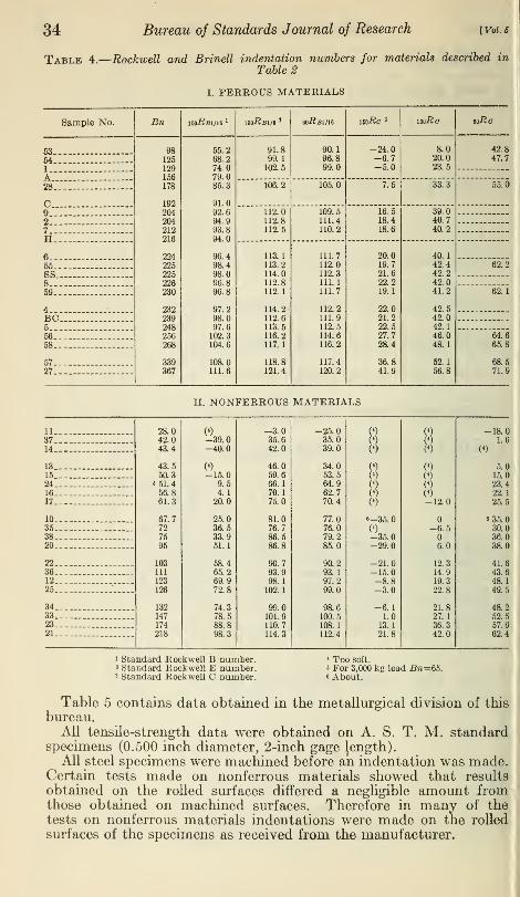
Table 4.
—
Rockwell and Brinell indentation numbers for materials described in
Table 2
I. FERROUS MATERIALS
Sample No. Bn loo-Rai/ie l ioo-Rbi/8 ' 60i?Bl/16 wRc 3 loo-Rc eo-Rc
53 ._ 98125129156
178
192204204212216
224225225226230
232239248256268
339367
55.268.274.079.085.3
91.092.694.993.894.0
96.498.498.096. 896.8
97.298.097.6102.3104.6
108.0111.6
91.899.1102.5
90.196.899.0
-24.0-6.7-5.0
8.020.023.5
42.8
54 -. 47.7
1
A28... 106.2 105.0 7.5 33.3 55.0
cg 112.0
112.8112.5
109.5111.4110.2
16.518.418.6
39.040.740.2
27
H6 113.1
113.2114.0112.8112.1
114.2112.6113.5116.2117.1
118.8121.4
111.7112.0112.3111.1111.7
112.2111.9112.5114.6116.2
117.4120.2
20.019.721.622.219.1
22.021.222.527.728.4
36.841.9
40.142.442.242.041.2
42.542.042.146.048.1
52.156.8
55 62.2
SS869 62.1
BC .
66. 64.6
68.. 65.8
68.527. . 71.9
II. NONFERROUS MATERIALS
11.-- 28.042.043.4
43.550.3
• 61.456.861.3
67.7727595
103111
123
126
132147
174218
(4)
-39.0-40.0
(«)
-15.09.54.120.0
25.036.533.951.1
58.465.269.972.8
74.378.588.898.3
-3.035.642.0
46.059.666.170.175.0
81.076.786.586.8
90.793.998.1102.1
99.0101.9110.7114.3
-25.035.039.0
34.053.564.962.770.4
77.076.079.285.0
90.293.197.299.0
98.6100.5108.1112.4
l
i
(4)
w(<)
6-35.
0)-35.0-29.0
-21.0-15.0-8.8-3.0
-6.11.0
13.121.8
(4)
0)W0)(4)
(*)
(4)
-12.0
-6.5
6.0
12.314.919.3
22.8
21.827.136.342.0
-18.037 1.6
14 (4)
13 5.015 15.024 23.416 22.117 25.5
10 fi 35.035 30.038 36.020 38.0
22 41.636... 43.612.-. 48.125 49.5
34 48.233 52.523 57.621 62.4
i Standard Rockwell B number.' Standard Rockwell E number.' Standard Rockwell C number.
* Too soft.s For 3,000 kg load Bn=65.6 About.
Table 5 contains data obtained in the metallurgical division of this
bureau.All tensile-strength data were obtained on A. S. T. M. standard
specimens (0.500 inch diameter, 2-inch gage Jength).All steel specimens were machined before an indentation was made.
Certain tests made on nonferrous materials showed that results
obtained on the rolled surfaces differed a negligible amount fromthose obtained on machined surfaces. Therefore in many of thetests on nonferrous materials indentations were made on the rolled
surfaces of the specimens as received from the manufacturer.

Rockwell-Brinell Relationships 35
The Rockwell indentations on each specimen were located betweenand near the Brinell indentations. Each experimental indentation
number listed in the tables is the average obtained from at least four
indentations.
The following study was made on each of five Rockwell brales.
By means of a contour measuring projector giving a magnification of
234, a shadow of the brale was formed on a screen, the shadow being
a projection of a cross section of the tool through its axis. The out-
line of the shadow was carefully traced. A second and a third trac-
ing were obtained after the brale had been rotated 60° and 120°,
respectively, about its axis.
Table 5.
—
Data on steels furnished by metallurgical division, Bureau of Standards
Sample No.BrinellNo. ioo-Rbi/ib wRc
Experi-mentaltensile
strength
16-3 125128131134156
157161165167168
169169170170170
170173173174174
175180181181184
187189191192193
194195197197197
198199204207209
209215223226229
229229229229229
71.470.177.775.783.1
83.486.085.585.883.9
86.987.484.586.5.
87.2
87.585.086.787.086.6
89.789.789.689.388.9
89.290.390.091.791.3
91.892.495.393.591.3
94.691.492.692.995.5
94.598.797.1100.098.4
97.596.899.595.095.0
Lbs./in*68, 500
16-4 .. 69,20029-2 70,00029-1 -. 69,5008-R 82,500
84,5002-F -.
2-CA 84,5002-C 85,00015-7. 91,00017-1 ... 87,300
2-Q 86,50034-1 77,5007-2 ... 87,3008-FA 83, 0008-RA 86, 000
15-1 92,50015-8 91,0008-F 84, 5003-FA 92,00034-2 77,500
6-FA 91,0006-F 91,5001-FA 93,0001-F 92,500
92,5009-RA
3-F 92,0009-FA 93,0009-F 93,5001-RA 96,0003-RA _ 92,000
3-R 98, 0001-R 97, 000
103, 0005-A 12.635-1-. 92,00036-2 99, 500
35-2 93,50036-1 99, 0006-FA 102, 0005-F 103, 5006-RA 101, 500
6-R 101, 5006'.. 16.8 102, 5009-R 100,00025-A-l 20.2
21.3113,500
7-FA 114, 500
6-RA 116, 0005-R 115,00025-A-2 21.1 115, 50019-1 107, 60019-2 107, 000

Bureau of Standards Journal of Research
ImetallurgContinued
36
Table 5.
—
Data on steels furnished by metallurgical division, Bureau of Standards—
Sample No.BrinellNo. l00i?Bl/l« iwRc
14-RA.14-F...13-O-A11-F...13-0...
13-CA.13-0...32-1....12-FA.12-C...
12-CA.12-F...32-2....33-1....33-2....
11-R...10-A-2.11-RA.10-F...10-FA.
7-RA..7-R....11-FA.10-R...ll-A-4.
10-RA.12-RA.28-4....
12-R...26-1-A.
14-A-2.11-A-l.14-A-l.15-A-2.12-A-2.
12-A-l.15-A-l.30-A-8.10-A-l.20-2-...
20-1....20-4....
25-2....20-3...25-1....
27-A-6.27-A-3.I-9D..I-32D.I-28B..
I-8B..I-32C.I-9C.I-28A.I-30D.
I-10D.I-16B.
247 99.0 23.8248 100.3 24.9250 101.6 25.9252 101.1 25.3254 101.5 25.9
255 100.4 26.0255 101.1 25.8255 101.3 23.3256 101.4 26.5257 103.9 25.5
257 102.9 25.7260 101.5 27.0262 101.2 23.3262 101.9 24.8262 102.4 26.2
265 103.0 26.8265 100.4 27.2267 103.1 27.6267 102.3 26.6269 102.8 27.6
270 103.0 28.8273 103.0 29.4273 102.8 27.7285 104.7 30.0288 101.9 27.7
293 105.2 32.2297 105.9 31.0300 107.1 31.1300 105.9 32.8302 106.4 33.5
304 106.1 34.5305 104.3 29.3306 105.9 34.4311 104.6 32.0317 105.9 33.6
321 106.3 33.5321 105.2 32.5330 110.1 32.9334 110.8 34.4341 113.4 33.2
363 112.8 36.4363 113.9 35.0363 112.7 36.4375 114.4 36.2388 115.0 41.2
388 114.5 39.8395 115.0 40.5407 41.9408 42.4434 43.6
450 45.9512 50.5518 60.0525 51.0527 51.1
53ft 52.2542 51.7

Petrenko) Rockwell-Brinell Relationships
Table 6.
—
Table of values for diamond brale
37
fto
ftoM vanes
nfromOto
0.0666S
' 0. 07 S.10S.15S.20S
H .30 5«D .40Ss .50S
.60S
.70S
.80S
.90SI 1. 00 s
H f 1. 10 S~J 1.20S|i 1.30SQ I 1. 40 S
0.10S.20S.30S.60S
0. 049 S.453S1.012S1. 487 S
2.286S2.963S3. 559 S4. 100 S
4. 596 S5. 059 S5. 494 S5.905S
6.306S6. 705 S7. 103 S8.293S
Rockwell Cnumber load
150 kg
Rockwell Cnumber
varies from(100-466.7 S)
to 100
100- 489. 5 S100- 676. OS100- 931. OS100-1, 143 S
100-1, 493 S100-1, 781 S100-2, 030 S100-2, 250 S
100-2, 448 S100-2, 630 S100-2, 797 S100-2, 953 S
100-3, 103 S100-3, 253 S100-3, 402 S100-3, 846 S
Brinellnumber
Brinellnumbervariesfrom3.199
S3to oo
3. 048/S*2. 133/S21. 422/S21. 066/Sa
.711/S2. 533/S2
. 427/S2
. 355/S2
. 305/S*
. 267/S2
. 237/S*
. 213/S2
. 193/S2
. 176/S2
. 161/S2
. 127/S3
For S= 0.0224 mm
Bn
33, 324
16, 66211, 1088,3316,6656,378
6,0754,2512,8342,125
1,4171,062
851708
532472425
385351321253
noRc
1009896
89.084.979.174.4
60.154.549.6
45.241.137.433.9
30.527.223.813.8
1
0.0055.0077.0095.0110.0123.0125
.0128
.0153
.0188
.0217
.0307
.0343
.0376
.0406
.0434
.0460
.0485
.0510
.0534
.0558
.0629
For S=0.0291 mm
Bn
25, 65112, 8268,5506,4135,1303,778
3,5992,5191,6791,259
840629504419
315280251
228208190150
180-Rc
100
85.880.372.966.7
56.648.240.934.5
28.823.518.614.1
9.75.31.0
-12.0
1
y/Bn
0.0062.0088.0108.0125.0140.0163
.0167
.0199
.0244
.0282
.0345
.0399
.0445
.0527
.0563
.0597
.0631
.0725
.0817
1 492 9For Case I corresponding values of Bn and mRc are calculated by use of the formula -Bn3E
<gnoo— R )
*
A circle was then drawn for each tracing, fitting as closely as pos-sible the curved portion. The lines bounding the conical portionwere extended to determine the point D. (See fig. 3.) Values of
OD and r could then be determined. These data are found in
Table 7.
The extent to which the experimental Brinell and Rockwell num-bers obtained in this investigation may have been influenced byPeculiar characteristics of the particular machines used is not known,i No attempt was made to find and interpret any systematic differ-
mces in the experimental values for steels which might result fromlifferent treatments. A. Heller 6 has shown that depth of hardenings a very important factor to be considered in deriving conversionormulas for steels.
6 American Machinist, Apr. 4, 1929.

38 Bureau of Standards Journal of Research
Table 7.
—
Data on Rockwell diamond brales
[Vol.5
Manufacturer's No.
26-1886.
26-1832.
26-15.
29-1893.
26-224.
Position lAngle of
cone
120120 6120 18
119 55119 51
120 3
120 1
120 1
120 18
119 41
119 32119 53
120 25120 4119 48
mm0.200.180.192
.182.
.167
.202
.191
.201
.212
.200
.197
.205
.198
.197
CD
mm0. 0336.0293.0315
.0271
.0271
.0326
.0315
.0315
.0326
.0336
.0326
.0315
.0315
.0315
S calculat-ed from r
mm0. 0268.0241.0257
.0244
.0224
.0267
.0271
.0256
,0284,0268,0264
,0275,0265,0264
S calculat-ed from CD
mm0. 0291.0254.0273
.0235
.0235
.0282
.0273
.0273
.0291
.0282
.0273
.0273
.0273
i The brale was turned into position 2 from position 1 by rotating it
60° rotation brought it into position 3.
* The meaning of the notation used in this table is given in fig. 3.
about its axis. An additional
VII. CORRELATION OF APPROXIMATE THEORY ANDEXPERIMENT
When one plots the first three equations of Table 1 using values of
RB and -^- as coordinates, straight lines are obtained. Likewise,
1the second three equations give straight lines if values of Rc and
y/JDll
are used as coordinates. Graphs of the first, second, and fourth of
these equations are shown by dash lines in Figures 4 and 5.
The curve forming the upper boundary of the shaded area in Figure5 was plotted from data found in columns 7 and 8, Table 6, and the
curve forming the lower boundary was plotted from values found in
columns 10 and 11.
The upper curve gives the theoretical relationship between Bn and
uoRc for a brale in which S= 0.0224 mm, and the lower curve does the
same for a brale in which S= 0.0291 mm. These particular values of
S were chosen merely because they were the minimum and maximumvalues found in the study of the five tools and may represent anextreme variation in S. Average values would show less variation.
Certain facts are made evident by an inspection of the theoretical
straight line curve (for a true cone) and the theoretical curves bound-ing the shaded areas.
The effect of the spherical portion of the brale upon the theoretical
relationship between Bn and i 50Rc is quite small for 15QRc=lO }but
gradually increases and becomes quite large at i 50Rc = 70.
If two brales are used having different values of S, the effect of
this difference in S is quite small for i50Rc = 10, but becomes consider-
ably larger at i 50Rc = 70.
Thus the theoretical value of Bn corresponding to mRc = 70 is
1,678 for £=0.0224 mm and only 1,460 for £=0.0291 mm.Experimental values taken from Tables 3 and 4 are plotted in
Figures 4 and 5. Considering Figure 4, we see that the points donot fall along the theoretical straight lines, but that their mean

Petrenko] Rockwell-Brinell Relationships 39
positions are determined fairly well by the two full lines. SinceC
these are straight lines, equations of the form Bn = -pr-^—^-r can be(loU Kb)
used as conversion formulas. The numerical values to be substitutedfor C are the reciprocal slopes of the experimental curves. Thus, the
•30 -20 -JO JO 20 30 40 SO 60
Roctcwellnumberjoo i/o im no
Figure 4.
—
Relation of Brinell numbers to Rockwell ball numbers
146iiprocal slope of the iooRbihq line is
Bn=
wv = 7,300, and the equation is:
7,300
(130— loo^BiZie)
Equations (a), (b), and (c) of Table 8 were obtained in this way.The experimental points plotted in Figure 5 determine a curve
Fhich is displaced from the theoretical curves. As would be expected,

40 Bureau of Standards Journal of Research [Voi.s
its general form is like that of the theoretical curves for a brale witha spherical apex.
This curve was used to determine the empirical equations:
„ 1,520,000- 4,500 l50Rcun~ (ioo- 150iW 2
and
n 25,00 -10 (57 - mRc)2
(d) and («) ofm 100- 150#<7 Table 8
which hold in the ranges i 50Rc greater than 10, less than 40 and ir,oRcgreater than 40, less than 70, respectively.
Table 8.
—
Empirical relationships between Rockwell and Brinell indentationnumbers
7 300 (For ioo-Bj5i/ie greater than 40 and less than 100.
(a) Bn= '—^ {Error to be expected not greater than plus or minus 1016U— ioo«fii/ie[ percent.
3 710 l^or 100^ B1 /8 grater than 30 and less than 100.
(6) Bn= . or.
'—n— {Error to be expected not greater than plus or minus 10lcJU— ioo/tsi/8[ percent.
(c) gn= 1ort' p fThis load is not recommended by manufacturer.
, . „ 1,520,000 -4,500 mRcllOT 150?c greater *?*? 10
+and le
+SS^ 4
°i(d) Bn=- tVt^ p N ,{Error to be expected not greater than plus or{WU-mKcy| m inus 10 per cent.
25000—10 (57— 2?0 2 (^or 150^ c greater than 40 and less than 70.
(e) Bn=—'-
inr>— 16° c)
{Error to be expected not greater than plus orluu- 160tfc
( minus 10 per cent>
(/) Bn= ,. nr.'—p-Y2 fThis load is not recommended by manufacturer.
(g) ^w= mqq_!, p \8jThis load is not recommended by manufacturer.
100#B1/16= 1.97X 100^iBl/8— 126
100#£1/16= 1.81 XoO^Bl/16- 105
ioo^c= 1.518Xeo^c— 51.8
The general form of the first of these equations was suggested bythe fact that for values of mRc less than 40 the experimental curveis very nearly parallel to the theoretical straight line. For valuesof mRc greater than 40 the spherical portion of the brale has a verynoticeable effect. This was an indication that the general form of
the second equation should be like that for a ball indenter.
Equations (/) and (g) of Table 8 were obtained by following the
procedure used in getting equations (a), (6), and (c). In place of
each of these equations we should very likely have two equationssimilar in form to (d) and (e). There was not sufficient data available
for checking this point.
The last three equations of Table 8 were obtained by equatingvalues of Bn taken from this same table. These equations differ verylittle from the corresponding theoretical equations of Table 1. Agraphical comparison of two cases is made in Figure 6,

Fttmiko] I\ockircll-Ih-incJl Relationships 11
7hetYtficol'clrm:
B - for Brait trhose tip is spbtrica/stymtnffaring 0/fttydt OOZtimm.
~ C ~ far 3mfe *rA\ft tip is «r v»- -. •
segmtnt hiring atritudt <xoz9i mm.
1000+
\£ 900'
I
000
<^
erpfr/rrxntnt curre.«.._ t-V».V\V -45CO rfft*"
0OQ-Zf?<PfO<**/?c < 40
aos
l\\<
aoofO 20 30 40 50 SO 70 to 90 100
ftock»*ll Cnumber-food no hg.
Fhu'ke 5.
—
Relation of Brinell numbers to Rockwell cone numbers
120
/
/
/
80i
/• A
*»n?c *t49/**efo-**//
/•
•ft
1 1
//. /i mfta= 'Z ' .>• ?94 -HO
*w/J5r ** *>/&
•
*Jf~-:- ffaorrtica/
rill1? /
[
11 1
I" •/.
<£
*»*ef?C ' r.Wvftc-fi
expenmenfoi \£
5 //
•
9 o -rrr nous marff '/a/s
rjfrrroh
c
r
//• - Abn-ffrmv m
1 1
//
'/
1v~~"mdbA - r.97 'to/Fbi1-/**
soA //
/,/
9
40/
/
/'
J//
. tf20 40 60 BO /OO ISO
Figure 6.
—
Comparison of Rockicell numbers
42 Bureau of Standards Journal of Research [Vol.i
A comparisoD of Tables l and 8 shows bhat in every case:
(/>'//) theorX(130-JBa) bheor>(5n) exptx(130-ik) expt and(/in) bheorX(100 -Rc)
s theor>(Bn) exptX (100 -Be)* e*pt. Theexplanation for this is in part as follows:
1. The flattening of the BrineU baU duo fco compression probably
results in an area of indentation Larger than one would obtain with a
rigid ball. Consequently (/>/>) bheor>(2?n) expt.
2. Elastic recovery of the materia] and deformation of the indenting
fcool due bo compression bend to make the Rockwell indentation shal-
lower Mum it would bo if (ho material were perfectly plastic and tho
boo] rigid. As a result:
( EB) bheor<(£B) expt and (Bo) theor< (2?c) expt
or
(130 /^)thoor {\ M) - h\f ) cx\)t tuu\(W0-
R
c ) t\^ory (100-Rc) expt.
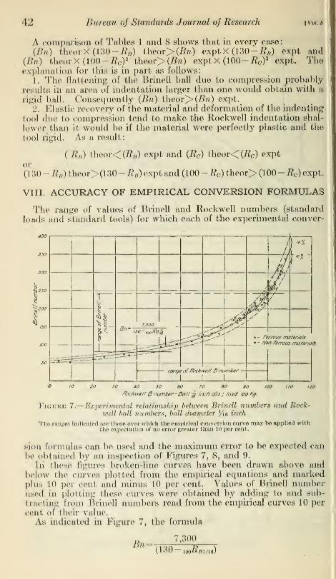
VIII. ACCURACY OF EMPIRICAL CONVERSION FORMULAS
The range of values of BrineU and Rockwell numbers (standard
loads and standard tools) Tor which each of bhe experimental conver-
ge JO 40 50 60 70 SO 90 100 110 UOi.'\ >./»/// 3 number- Da//% incf) a/in.; J<xtd /oo kg.
Figure 7. Experimental relationship between BrineU numbers and Rock'Well ball numbers, ball duuneter ,' (ft ineh
The ranges ladio»ted are those over whlob theemplrloal conversion curve may be Applied withthe expectation of do error greater iimn LO per cent.
sion formulas am be used and fche maximum error to bo expected can
be obtained by an inspection of Figures 7, 8, and 9.
In these figures broken-line curves have been drawn above andbelow bhe curves plotted from bhe empirical equations mu\ markedplus io per cent ami minus 10 per cent. Values o( BrineU numberused in plotting those curves were obtained by adding bo and sub-
tracting from BrineU numbers read from bhe empirical curves io per
oent of their value.
As indicated in Figure 7, bhe formula
Bn,300
U30 looRaint)

PsfrenAoJ Rock wcll-Bri'mil Relationships 43
can be used for fche range of Rockwell B Dumber (ball )£« uioh di-
ameter; Load l()() kg) from 10 to 100 or of Brinell uumber from 80fco 240. All of the experimental points in this range fall within the10 per cent Limits. The upper end <>• the range is sol. at mRm i\*
loo.
even though there seems to bo good agreement botwoen theory andexperiment for larger values of mRm/u- This is done because the
to
UioJ
i
ti
1
Ji7/ //
i
////4l
6 "'Ij* -<
!
A7- J7/S
o »
Vi ^^-- "Z>* • - Abn-frrrvus matsrta/s
I r^V^_^_^^i«""""_ »--'
It*™-Rockwel/L 1
/JO30 40 50 60 . 70 80 90 100 IIO
ftochmJ/d number - 0a//'$ inc/i dta., loadtooHg.
PlGTJRB 8.
—
Experimental relationship between Brinell numbers and liockwell
ball numbers, ball diameter Ya inch
The ranges Indicated are those over which the emplrloa] con version curve may i>o applied wii.ii
the expectation of do error greater than LO per oent,
relative efTect of an error in U){)Rm/u\—that is, the ratio of the error
to (130— looRmnn)— is very large when loolimm *s greater than L00.
As shown in Figure 8 the formula
ftt- «,w. ' '
3,710
10()'»7M/H
lmlds about equally well throughout the range of Rockwell B number(ball % inch diameter; load LOO kg) from 80 to 1 00 or of Brinellnumbv >m 40 to L25. The check on the accuracy of this formulais not conclusive because of insufficient data.As shown in Figure 9, the formula.
_ 1 ,520,00 - 4,50 X mRrJM ~(lOO-wo^c)8
holds for tho range of Rockwell C number (load 150 kg) from 10 to

44 Bureau of Standards Journal of Research [Vol. 5
40 or of Brinell number from 180 to 370. Ninety-five per cent of
the experimental points fall within the 10 per cent limits.
Likewise, the formula
25,000-10 (57- 150i2c)2
Bn=100-iavfl.IbQ^C
holds for the range of Rockwell C number (load 150 kg) from 40 to
70 or of Brinell number from 370 to 770. All experimental points
in this range fall within the 10 per cent limits.
30 40 50
/foc/ftvt// Cnumber-kx*a//50 kg.
Figure 9.
—
Experimental relationship between Brinell numbers and Rock-well cone numbers
The ranges indicated are those over which the empirical conversion curve may be applied withthe expectation of no error greater than 10 per cent.
IX. RELATIONSHIP OF ROCKWELL NUMBERS TO TENSILESTRENGTH
Earlier investigators 7 have established the fact that a rough pro-portionality exists between the tensile strength of steel and its Brinellnumber.The equations sometimes used in calculating the tensile strength
of steel 8 are:
Tensile strength (lbs. /in.2) = 515 Bn for Brinell numbers less than 175.
Tensile strength (lbs./in.2) = 490 Bn for Brinell numbers greater than 175.
' Die Brinellsche Kugeldruckprobe, P. W. Dohmer, Berlin; 1925.8 See Die Brinellsche Kugeldruckprobe, P. W. Dohmer, Berlin, p. 48; 1925.

Petrenko] Rockwell-Brinell Relationships 45
Since an empirical relationship between Bn and ioo#si/i6 has beenfound (see Table 8) the above equations can be transformed to read:
*
o yah nnnTensile strength (lbs. /in.
2)= T5^ ^ for loo&Bi/ia less than 88.
130 loo-^Bi/ie
Tensile strength (lbs./in.2) = -r— ~ for mRBl/l6 greater than 88.
lt3U 100^B1/16
The dash hnes in Figure 10 are the graphs of these equations.
86 88 90 92 94 96 98 100 102 104 106 108 IH>
focMwe//6 number- /ba//£ inch ctia., toadtoo hq.
Figure 10.
—
Experimental relationship between the tensile strength
of steel and Rockwell ball number, ball diameter Ke inch
The ranges indicated are those over which the empirical conversion curve may beapplied with the expectation of no error greater than 15 per cent.
The full line curve in Figure 10 is the graph of the empiricalequation
:
4,750,000- 12,000 X 100i?B1/16Tensile strength (lbs./in.2)=
130 100-^51/16
the general form of which was suggested by the last two equationsgiven above. None of the experimental tensile strengths differ fromcorresponding values obtained from this curve by more than 15 percent. It is suggested that this equation be used over the range of

46 Bureau of Standards Journal of Research [Vol. 5
Rockwell B number (ball Ke inch diameter; load 100 kg) from 82 to
100 or of tensile strength from 80,000 to 120,000 lbs./in. 2.
If values of Bn in terms of i50Rc (see equations (d) and (e), Table 8)
be multiplied by 490 the following expressions are obtained:
Tensile strength (lbs./in. 2) = ^ffi,? ~
22pX
.
1
2
5°i?c)for 150RC less than 40.
mju— 150-ttc)
Tensile strength (lbs./in.2)=
greater than 40.
These equations are plotted in Figure 11
490 (25,000 - 1 (57 - i5o^c)2)
100 -i50#C7for 150i?c
I60QOO
140000
» 120000
t tensile strength' 49oBn •
•"5(74SO-Z2,soRc)
(lOO-isofc)^^'^ c
+»"&&&*
range of ffockwe/t C nvmher-
10 20 JO 40 SO 60
fibcktvet/ C number - had 150 kg.
Figure 11.
—
Experimental relationship between the tensile strength of steel
and Rockwell cone numberThe ranges indicated are those over which the empirical conversion curve may be applied with
the expectation of no error greater than 15 per cent.
The full line curve in this Figure 11, which seems to satisfy theexperimental data better than the dash line curves, especially in therange above i 5oJ?c
= 40, is a graph of the empirical equation:
Tensile strength (lbs./in.2)= 105(7,000-10X 15(>£C)
(100- 15oifc)2
None of the experimental values differ by more than 15 per cent fromcorresponding values read from the full line conversion curve. This

Petrenko] Rockwell-Brinell Relationships 47
accuracy is about the same as that holding in a conversion fromBrinell number to tensile strength.9
It is suggested that this curve be used only over the range of Rock-well C number (load 150 kg) from 10 to 40 or of tensile strength from90,000 to 190,000 lbs. /in.
2. The experimental check on the curve in
the range above i50Rc — 40 is not sufficient to warrant using it as aconversion curve. With the exception of the two aluminum alloys
(Nos. 11 and 12), which fall in line with the ferrous alloys, the non-ferrous alloys snowed no definite relationships between tensile
strengths and Rockwell numbers. This was to be expected in viewof the failure of previous investigators to find definite relationships
for nonferrous metals (with the exception of aluminum alloys) be-
tween tensile strengths and Brinell numbers. The recent work of
Schwarz 10 indicates that no general relationship between tensile
strength and a single indentation number is possible, the approximateproportionality existing for steel and duralumin being the result of
their relatively high elastic ratio.
X. RESULTS OF EARLIER INVESTIGATORS
The desirability of having some means for comparison of the Rock-well and the Brinell numbers was recognized with the increased useof the Rockwell machine. During the last few years several investi-
gations have been made for the purpose of obtaining the experimentalrelationships between the Rockwell and the Brinell numbers. Thesummary of these investigations and the principal results obtainedare found below :^
1. S. C. Spalding, Transactions of the American Society for Steel
Treating, October, 1924.
The experiments were made on steels having a tungsten contentof about 17 per cent and drawn at different temperatures. Theresults showed that within the range Bn greater than 300 and less
than 650 the Brinell number is linearly related to the Rockwell conenumber. No conversion formula was recommended, but the rela-
tionship between the Rockwell cone number and the Brinell numbermay be roughly expressed by the equation
Bn= 12.
5
mRc- 137
2. I. H. Cowdrey, Transactions of the American Society for SteelTreating, February, 1925.
Many ferrous and nonferrous materials were tested, including over-strained, cold-worked, and heat-treated material. The followingequations were derived:
T>„_. 100-^51/16 + 2736.49- 0.048 X 1QQRB1/U
and
Bn=88.3 |
8 See Relation Between Maximum Strength, Brinell Hardness, and Scleroscope Hardness in Treatedand Untreated Alloy and Plain Steels, by R. A. Abbot, Proc. Am. Soc. Test. Mat., 15; 1915.
i° Otto Schwarz, Zugfestigkeit und Harte bei Metallen, Forsehungsarbeiten auf dem gebiete des Inge-nieurwesens, Heft 313; 1929.
115233°—30 4

48 Bureau of Standards Journal of Research [Vol. 6
3. R. C. Brumfield, Transactions of the American Society for Steel
Treating, June, 1926.
These tests also included nonferrous materials and steels treated in
various ways. The following equations were derived:
Bn = 6,600
127 Mand
100**B1/16
R 1,880,000^-(112-
150BC)2
The results obtained in these investigations are plotted in Figures12 and 13. In Figure 12 the Brinell and the Rockwell numbers are
6.S -doreouofStandardsC 'Itl.Cowdrey, 7rdnsAS5T,feix tsz$ I
S'RHBnjmf/ekfTransJSST.June/xe f.
- S=S.C.SpaMng,Trans.A5.SZ0cr.i9Z4-jf-
40 60
ftbckwe// numbers
Figure 12.
—
Relationships between Brinell and Rockwellnumbers given by different investigators
plotted using uniform scales, so that a ready comparison of the Brinell
numbers computed from the Rockwell dumbers can be made. In
Figure 13 the Rockwell numbers are plotted: mRmn<> against di»
and 160#c against i_ » as was done in Figures 4 and 5. In this way->JBn
the differences between the various equations are brought out moreclearly.

Petrenko] Rockwell-Brinell Relatiotiships 49
It will be noted that Brumfield's equations are of the same type as
the equations given in this paper. The agreement between the twogroups of equations is fairly good, except for the upper range of theRockwell cone number.
XI. SUMMARY
The tensile strengths and the Brinell and Rockwell indentationnumbers were obtained for a variety of ferrous and nonferrous metals.
tee.6
ISSjO
100.0
03.3
71.4
03.5
33.3
sao
10,000JO 43.3
3300.0 41.
7
1,111.1 38.3
633.0
400.0
£77.7
304.
1
136.3
133.3
100.0
*&£
. j»S
s s'
f,<&
y
#yBo ^'ooA»i
/
1
B.S-J //y//
/ v/
/y ACowirey
—'1Irumi
7*
7e/U
/
// \
I
/
//
/r
/j?^
Bn^/sofrb
ASpc'/d/nq
&.5^i<
irCowdrey
/ * \\' Brunf/e/d
/
.01
.03
.03
.04'
.05
.06
.07
.09
i
o
.003
.00*
.009
.008
.010
.013
.014
.018
.018
,020
.033
.034
.036
%
H!§
•20 «/0 O tO 30 30 40 SO tO 70 80 90 100 110 ISO 130
PockweIt numbers
Figure 13.
—
Relationships between Brinell and Rockwell numbers obtainedby different investigators
Rockwell number vs. ,
—
and-p-
1. The experimental indentation numbers made it possible to obtain
j
semiempirical formulas for calculating Brinell numbers from Rockwellnumbers, or vice versa. When used over the range specified each ofLthese formulas gives values in which the error to be expected is not(greater than plus or minus 10 per cent.

50 Bureau of Standards Journal of Research [voi.s
Using the following notation:
loo^sizie; Rockwell B number, ball % 6 inch diameter, load 100 kg.
100Rmi8', Rockwell B number, ball )i inch diameter, load 100 kg.
isoRc', Rockwell C number, brale, load 150 kg.
these equations are:
7 300(a) Bn= i rtn
'—o for ioo#bizi6 greater than 40 and less than 100.lOU— 100^51/16
3 710(6) Bn= . or.
'—p— for woRmis greater than 30 and less than 100.J-oU 100^51/8
, N D 1,520,000-4,500 l50Rc , r> + A in A i
(c) Bn=— jzr^. p v 2 lor 150RC greater than 10 and lessV 1UU — i5ofi>c)
than 40.
,- n 25,000- 10 (57 - 150RC)2
f r> . + n A ~ , ,
(a) Bn=—-
inn —p lor 15Qltc greater than 40 and lesslUU — i5otic
than 70.
2. For steels the tensile strength may be calculated from the
Rockwell number, with expectation of an error less than plus or
minus 15 per cent, by using the empirical formulas:
/ x v m . ., nu r ^ 4,750,000-12,000 mRmI16 ,
(a) Tensile strength (lbs./m.2) = - '-j^. ^ *- for mRBni6loU— ioo-^Bl/16
greater than 82 and less than 100.
,M m n + ., ,i ,. 2 ^105 (7,000- 10 X 150RC) ,
(b) Tensile strength (lbs./m. 2)= L nn p-v^ for i5oi?c greater
\1UU 150^C>)
than 10 and less than 40.
3. The six equations given above have been plotted. On eachgraph additional curves are drawn, one above and one below the givenconversion curve, showing the maximum error to be expected in usingthe curve. The recommended range of application of each conversioncurve is indicated on the graph.
4. No discernible relationship was found between the tensile
strengths of nonferrous metals and their indentation numbers.
Washington, December 29, 1929.
Recommended