PSEN cs1.1p
Operating Manual-21095-EN-10
} PSEN sensor technology

PrefaceThis document is a translation of the original document.
All rights to this documentation are reserved by Pilz GmbH & Co. KG. Copies may be madefor internal purposes. Suggestions and comments for improving this documentation will begratefully received.
Source code from third-party manufacturers or open source software has been used forsome components. The relevant licence information is available on the Internet on the Pilzhomepage.
Pilz®, PIT®, PMI®, PNOZ®, Primo®, PSEN®, PSS®, PVIS®, SafetyBUS p®,SafetyEYE®, SafetyNET p®, the spirit of safety® are registered and protected trademarksof Pilz GmbH & Co. KG in some countries.
SD means Secure Digital

Contents
Operating Manual PSEN cs1.1p21095-EN-10
3
Introduction 5Validity of documentation 5Using the documentation 5Definition of symbols 5
Safety 6Intended use 6Safety regulations 6Safety assessment 6Additional documents that apply 7Use of qualified personnel 7Warranty and liability 7Disposal 8For your safety 8
Unit features 8
Function description 9Safety Device Diagnostics 10Operating distances 11Lateral and vertical offset 12
Wiring 12Terminal assignment connectors 13
Connection to evaluation devices 13Single connection 14Series connection 16Connection to Pilz evaluation devices 18
Teaching in the actuator 20
Installation 20
Adjustment 22
Operation 22
Dimensions in mm 23
Technical details 23Safety characteristic data 26
Supplementary data 27Radio approval 27
Order reference 27System 27
Contents
Operating Manual PSEN cs1.1p21095-EN-10
4
Accessories 27
EC declaration of conformity 29
PSEN cs1.1p
Operating Manual PSEN cs1.1p21095-EN-10
5
Introduction
Validity of documentationThis documentation is valid for the product PSEN cs1.1p from Version 2.0.
This operating manual explains the function and operation, describes the installation andprovides guidelines on how to connect the product.
Using the documentationThis document is intended for instruction. Only install and commission the product if youhave read and understood this document. The document should be retained for future ref-erence.
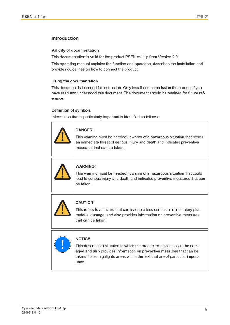
Definition of symbolsInformation that is particularly important is identified as follows:
DANGER!
This warning must be heeded! It warns of a hazardous situation that posesan immediate threat of serious injury and death and indicates preventivemeasures that can be taken.
WARNING!
This warning must be heeded! It warns of a hazardous situation that couldlead to serious injury and death and indicates preventive measures that canbe taken.
CAUTION!
This refers to a hazard that can lead to a less serious or minor injury plusmaterial damage, and also provides information on preventive measuresthat can be taken.
NOTICE
This describes a situation in which the product or devices could be dam-aged and also provides information on preventive measures that can betaken. It also highlights areas within the text that are of particular import-ance.

PSEN cs1.1p
Operating Manual PSEN cs1.1p21095-EN-10
6
INFORMATION
This gives advice on applications and provides information on special fea-tures.
Safety
Intended useThe safety functions of the safety switch are:
} Safe shutdown of safety outputs when the actuator is removed beyond the assured re-lease distance sar or when the actuator is not detected
} Remain shut down safely after the actuator has been removed
The safety switch meets the requirements in accordance with:
} EN 60947-5-3 with the actuator PSEN cs1.1 : PDDB
} EN 62061: SIL CL 3
} EN ISO 13849-1: PL e (Cat. 4)
} EN ISO 14119: Coding level Low, Type4
The safety switch may only be used with the corresponding actuator PSEN cs1.1.
The safety level PL e (Cat. 4 )/SIL CL 3 is only achieved if
} the safety outputs use 2-channel processing.
The following is deemed improper use in particular:
} Any component, technical or electrical modification to the product
} Use of the product outside the areas described in this manual
} Use of the product outside the technical details (see Technical details [ 23]).
NOTICEEMC-compliant electrical installation
The product is designed for use in an industrial environment. The productmay cause interference if installed in other environments. If installed in otherenvironments, measures should be taken to comply with the applicablestandards and directives for the respective installation site with regard to in-terference.
Safety regulations
Safety assessmentBefore using a unit it is necessary to perform a safety assessment in accordance with theMachinery Directive.
PSEN cs1.1p
Operating Manual PSEN cs1.1p21095-EN-10
7
Functional safety is guaranteed for the product as a single component. However, this doesnot guarantee the functional safety of the overall plant/machine. In order to achieve the re-quired safety level for the overall plant/machine, define the safety requirements for theplant/machine and then define how these must be implemented from a technical and organ-isational standpoint.
Additional documents that apply
Please read and take note of the following documents.
Only for use of the Safety Device Diagnostics (SDD):} Operating manual for the fieldbus module, for example SDD ES ETH or SDD ES
PROFIBUS
} System description "Safety Device Diagnostics"
For the use of passive junctions:} Operating manual of a passive junction, for example:
– PSEN ix2 F4 code
– PSEN ix2 F8 code
– PDP67 F 4 code
– PSEN Y junction M12 sensor
– PSEN Y junction M12 cable
You will need to be conversant with the information in these documents in order to fully un-derstand this operating manual.
Use of qualified personnelThe products may only be assembled, installed, programmed, commissioned, operated,maintained and decommissioned by competent persons.
A competent person is a qualified and knowledgeable person who, because of their train-ing, experience and current professional activity, has the specialist knowledge required. Tobe able to inspect, assess and operate devices, systems and machines, the person has tobe informed of the state of the art and the applicable national, European and internationallaws, directives and standards.
It is the company’s responsibility only to employ personnel who
} Are familiar with the basic regulations concerning health and safety / accident preven-tion,
} Have read and understood the information provided in this description under "Safety"
} Have a good knowledge of the generic and specialist standards applicable to the spe-cific application.
Warranty and liabilityAll claims to warranty and liability will be rendered invalid if
} The product was used contrary to the purpose for which it is intended
} Damage can be attributed to not having followed the guidelines in the manual

PSEN cs1.1p
Operating Manual PSEN cs1.1p21095-EN-10
8
} Operating personnel are not suitably qualified
} Any type of modification has been made (e.g. exchanging components on the PCBboards, soldering work etc.).
Disposal} In safety-related applications, please comply with the mission time TM in the safety-re-
lated characteristic data.
} When decommissioning, please comply with local regulations regarding the disposal ofelectronic devices (e.g. Electrical and Electronic Equipment Act).
For your safety
WARNING!Loss of safety function due to manipulation of the interlocking device
Manipulation of the interlocking device may lead to serious injury and death.
– You should prevent any possibility of the interlocking device beingmanipulated through the use of a spare actuator.
– Keep the substitute actuator in a safe place and protect it from unau-thorised access.
– If spare actuators are used, these must be installed as described inInstallation [ 20].
– If the original actuators are replaced with substitute actuators, the ori-ginal actuators must be destroyed before disposal.
} Do not remove the connector's protective cap until you are just about to connect theunit. This will prevent potential contamination.
} Switch off the supply voltage before disconnecting the plug-in connection.
} Make sure that when connecting or separating the connector the pollution degree 1 or 2is maintained.
} The connector should be protected from accidental loosening (e.g. using a cable tie).
Unit features} Transponder technology for presence detection
} Pilz coding type: Coded
} Dual-channel operation
} 2 safety inputs for series connection of multiple safety switches
} 2 safety outputs
} Safety Device Diagnostics (SDD)
– Safety Device Diagnostics can be used to poll sensor information, to perform ac-tions and to read configuration parameters

PSEN cs1.1p
Operating Manual PSEN cs1.1p21095-EN-10
9
– Manipulation protection in accordance with ISO 14119 (chap. 7.2.d) is possible byverifying the short name of the actuator through the controller via SDD communica-tion
} Diagnostic input for Y1 for Safety Device Diagnostics (SDD)
} Signal output/diagnostic output Y32 for Safety Device Diagnostics
} LED display for:
– State of the actuator
– State of the inputs
– Supply voltage/fault
} 4 directions of actuation
Function descriptionThe safety outputs may have a high or low signal, depending on the position of the actuatorand the signal status of the inputs.
In a safe condition there is a low signal at the safety outputs.
Electrical states of the inputs and outputs (when switch is ready for operation:Power / Fault LED is green):
Actuator inthe re-sponserange
Safety inputS11
Safety inputS21
Safety out-put 12
Safety out-put 22
Signal out-put Y32 (without useof the SDD)
Yes High High High High High
Yes Low Low Low Low High
No x x Low Low Low
Yes High Low High Low High
Yes Low High Low High High
x: High or low signal
Feasibility monitoring for safety inputs S11 and S21} If one safety input switches from high to low, while the other safety input remains high,
an unequal status is displayed: Input LED flashes yellow} If this safety input switches back from low to high, while the other safety input remains
high, a feasibility error is displayed and a partial operation lock is triggered: Input LEDflashes yellow
A switch to a high signal will only lead to normal switch operation if both inputs had a lowsignal. From this moment on, the switch to high may occur (partial operation lock see Errordisplay [ 22]).
} Diagnostic input Y1
If a fieldbus module of the SDD is used, the diagnostic input Y1 is automatically activ-ated and data is read.
If no fieldbus module of the SDD is used, the diagnostic input Y1 is not used.

PSEN cs1.1p
Operating Manual PSEN cs1.1p21095-EN-10
10
} Signal output/diagnostic output Y32
The status of the actuator is output. If a fieldbus module of the SDD is used, the signaloutput/diagnostic output for the writing of data is activated.
Block diagram
A1 A2 S11 S21
12 22 Y32
Y1
SDD Input
SDD Output
Power Input
Receiver Actuator
Safety Device DiagnosticsSafety Device Diagnostics is an option that can be selected independently of the safety-re-lated wiring.
When using the Safety Device Diagnostics, up to 16 sensors connected in series can beconnected as a subscriber to a fieldbus module.
The communication of the sensors with the fieldbus module is automatically built up againwith each new supply of the supply voltage. As a result, a sensor can be exchanged, e.g.when servicing, without the need for special measures.
An exchange can be detected via the fieldbus module e.g. through the serial number.
} With Safety Device Diagnostics there are the following diagnostic options for the field-bus module:
– Poll information of the sensors (examples: what sensor in the series has switched,at what point could there be an open circuit in the series connection)
– Read configuration parameters of the sensors (examples: Number of remainingteach-in processes, serial number of the switch)
– Perform actions (example: poll updated actuator name)
The results of the sensor diagnostics can be checked already during the installation phasevia the display in the fieldbus module, without the need to connect the fieldbus module tothe network.
} With Safety Device Diagnostics there are the following diagnostic options for the field-bus module for simple wiring:
– Information is passed on via the fieldbus module directly to the network

PSEN cs1.1p
Operating Manual PSEN cs1.1p21095-EN-10
11
– Mappings of the signal outputs to the sensor are automated by the SDD.
This prevents wiring errors and an expansion or reduction of the sensors is possiblewithout the need to change existing wiring.
– Wiring in accordance with IP20: Rapid installation in the control cabined is enabled.
– Wiring in accordance with IP67: Various passive junctions can be used (see Orderreferences for accessories [ 27]) to connect several sensors with only onecable from the field in the control cabinet.
Further information on Safety Device Diagnostics can be found in Additional documentsthat apply [ 7].
Operating distances
On
Off
Legend:} Sao: Assured operating distance: 15 mm
} So: Typical operating distance: 21 mm
} Sr: Typical release distance: 32 mm
} Sar: Assured release distance: 40 mm

PSEN cs1.1p
Operating Manual PSEN cs1.1p21095-EN-10
12
Lateral and vertical offset
Direction of actuation, front
[1]
[2]
[3]
[4] [4]
[5]
[6]
Po
we
r / Fa
ult
Sa
fety
Ga
te
Inp
ut
Direction of actuation at the side left-hand/right-hand[4]
[3]
[2]
[1]
[4]
[5]
[6]Safety Gate
Input
Power /Fault
Direction of actuation up/down
[1]
[2]
[3]
[4] [4]
[5]
[6]
[1] Hysteresis
[2] Typical operating distance SO
[3] Typical release distance Sr
[4] Offset in mm
[5] Operating distance in mm
[6] Response range
WiringPlease note:
} Information given in the Technical details [ 23] must be followed.
} The max. cable length lmax in the input circuit is calculated from
– the max. cable capacitance at the safety outputs (see Technical data [ 23]).
– the minimum permitted supply voltage at the sensor (19.2 V).
} When the safety inputs of the safety switch are controlled by an upstream device, andthey are not wired with 24 V,
– They must be monitored for shorts across the contacts in dependence of the Per-formance Level or SIL level to be achieved or
– The faults at the safety inputs that can occur by shorts across contact will have tobe excluded by suitable measures (e.g. wiring in accordance with EN 60204-1).
} The power supply must meet the regulations for extra low voltages with protective sep-aration (SELV, PELV).
PSEN cs1.1p
Operating Manual PSEN cs1.1p21095-EN-10
13
} The inputs and outputs of the safety switch must have a protective separation tovoltages over 60 VDC.
INFORMATION
Only use safety relays with a 24 VDC supply voltage. Safety relays with awide-range power supply or in AC device versions have internal potentialisolation and are not suitable as evaluation devices.
} The supply voltage to the safety switch must be protected with a 2 A to 4 A quick-actingfuse.
} Ensure the wiring and EMC requirements of IEC 60204-1 are met.
} When connecting in series, consider the requirements of manipulation protection andthe protection against bypassing or from overriding the safety switch (EN ISO 14119).
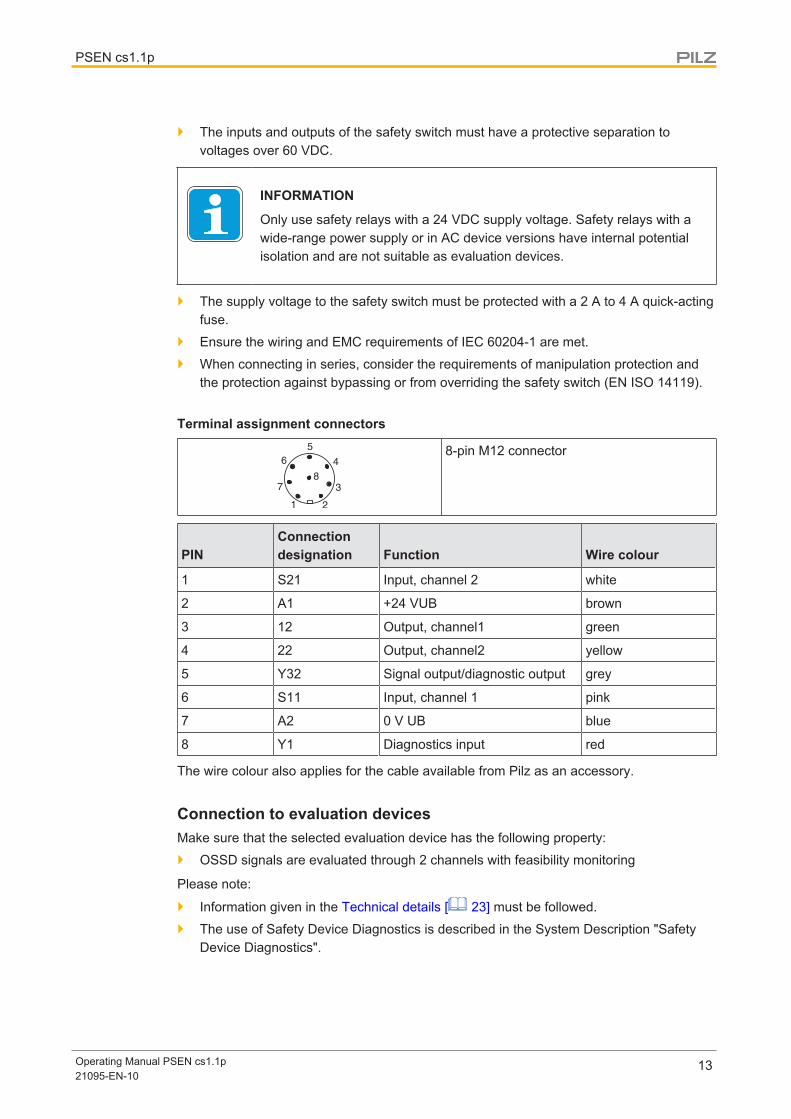
Terminal assignment connectors
8-pin M12 connector
PINConnectiondesignation Function Wire colour
1 S21 Input, channel 2 white
2 A1 +24 VUB brown
3 12 Output, channel1 green
4 22 Output, channel2 yellow
5 Y32 Signal output/diagnostic output grey
6 S11 Input, channel 1 pink
7 A2 0 V UB blue
8 Y1 Diagnostics input red
The wire colour also applies for the cable available from Pilz as an accessory.
Connection to evaluation devicesMake sure that the selected evaluation device has the following property:
} OSSD signals are evaluated through 2 channels with feasibility monitoring
Please note:
} Information given in the Technical details [ 23] must be followed.
} The use of Safety Device Diagnostics is described in the System Description "SafetyDevice Diagnostics".
PSEN cs1.1p
Operating Manual PSEN cs1.1p21095-EN-10
14
CAUTION!Do not connect the signal output to 0 V!
If the signal output Y32 is connected to 0 V, the safety switch may be dam-aged as a result. Connect the signal output Y32 to a consumer, e.g. to theinput on a control system, or leave the signal output unconnected. Also notethe max. current (see Technical details [ 23]).
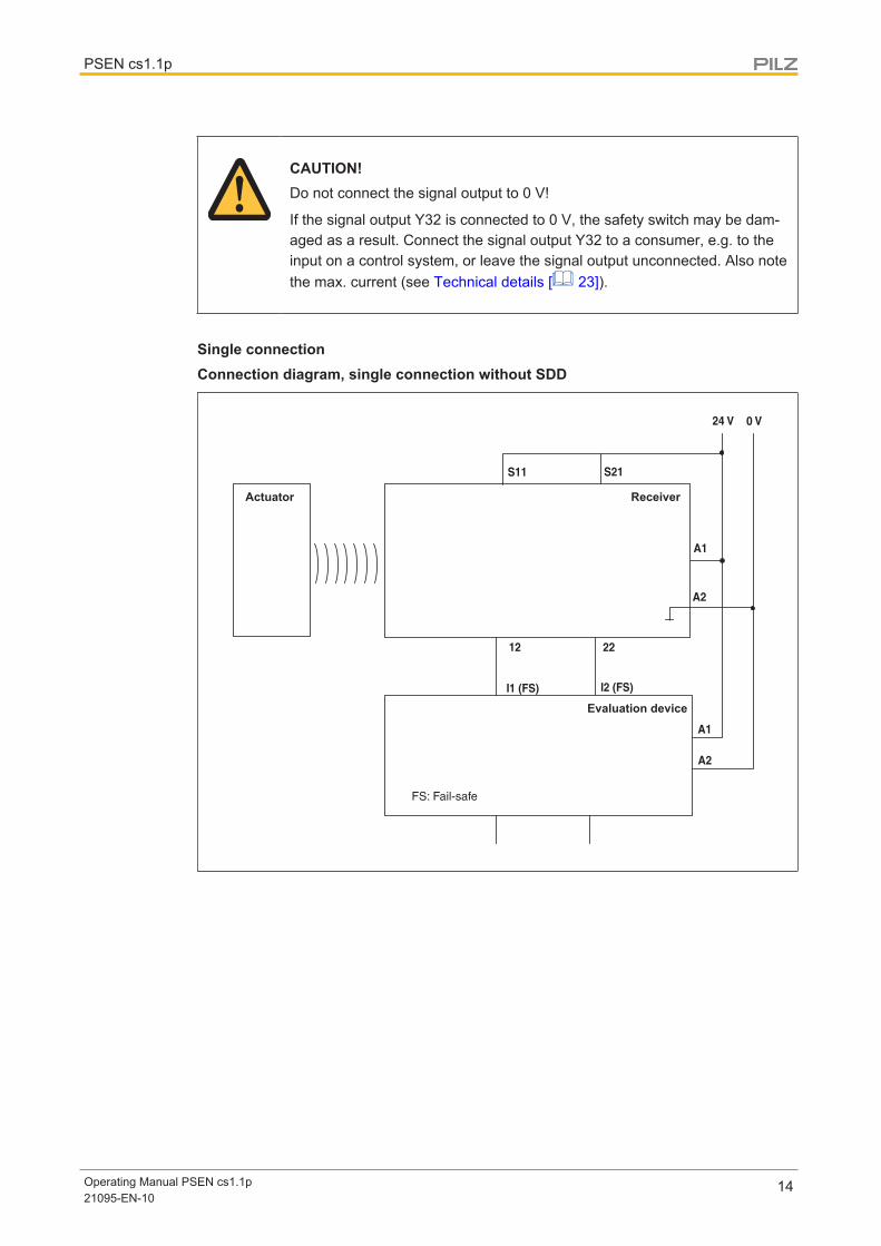
Single connectionConnection diagram, single connection without SDD
Actuator Receiver
Evaluation device

PSEN cs1.1p
Operating Manual PSEN cs1.1p21095-EN-10
15
Connection diagram, single connection with SDD
S21S11
24 V 0 V
A1
A2
12 22
I2 (FS)I1 (FS)
FS: Failsafe
A1A2
Y1
Y32
Rx Tx
Actuator Safety switch
Evaluation device
Fieldbus module

PSEN cs1.1p
Operating Manual PSEN cs1.1p21095-EN-10
16
Series connectionThe safety sensors PSENcode are also suitable for series connection with other sensors.
Maximum number of PSENcode sensors switched in series connections for SIL CL 3 usingSDD
} PSENcode large design (PSEN cs1.xp - cs2.xp): 8
When using other SDD-compatible sensors, the number must be recalculated.
In practice, the maximum possible number will be limited by the following parameters,among others:
} The required SIL level (e.g. SIL CL 3),
} the required performance level (e.g. PL e (Cat. 4)),
} the maximum delay or risk time permitted by the application.
Ensure there is sufficient supply voltage, taking inrush currents and fusing into considera-tion.
CAUTION!Extension of delay-on de-energisation
When several (n) devices are connected in series, the delay-on de-ener-gisation time adds with the number of interconnected safety switches. The max. delay-on de-energisation is made up of therisk time (see Technical details [ 23])+ (n-1) x max. delay-on de-energisation of the inputs + max. delay-on de-energisation of the evaluation device
} When making series connections using SDD, only use the following passive junctions.
– PSEN ix2 F4 code
– PSEN ix2 F8 code
– PSEN Y junction M8-M12/M12 PIGTAIL
– PSEN Y junction M12-M12/M12 PIGTAIL
– PSEN Y junction M12 SENSOR
– PSEN Y junction M12 cable channel

PSEN cs1.1p
Operating Manual PSEN cs1.1p21095-EN-10
17
Connection diagram, series connection without SDD
Actuator
Actuator
Control system
Evaluation device
Receiver
Receiver
ReceiverActuator

PSEN cs1.1p
Operating Manual PSEN cs1.1p21095-EN-10
18
Connection diagram, series connection with SDD
S11 S21
24 V 0 V
A1
A2
12 22
I1 (FS) I2 (FS)
FS: FailsafeST: Standard
S11 S21
S11 S21
12 22
12 22
A1
A2
A1
A2
Y1
Y1
Y1
Y32
Y32
Y32
TxRx
Actuator Safety switch
Evaluation device
Safety switch
Safety switch
Actuator
Actuator
Fieldbus module
Connection to Pilz evaluation devicesThe safety switch PSEN cs1.1p can be connected to Pilz evaluation devices, for example.
Suitable Pilz evaluation devices are, for example:
} PNOZelog for safety gate monitoring
} PNOZpower for safety gate monitoring

PSEN cs1.1p
Operating Manual PSEN cs1.1p21095-EN-10
19
} PNOZsigma for safety gate monitoring
} PNOZ X for safety gate monitoring
} PNOZmulti for safety gate monitoringConfigure the switch in the PNOZmulti Configurator with switch type 3.
} PSS for safety gate monitoring with standard function block SB064, SB066 orFS_Safety Gate
The correct connection to the respective evaluation device is described in the operatingmanual for the evaluation device. Make sure that the connection is made in accordancewith the specifications in the operating manual for the selected evaluation device.
The connections to two evaluation devices are shown on the following pages, by way of ex-ample:
} PNOZ s3 and
} PNOZmulti
A1A2
S12S22
A1A2
Y32Y1
S11
S211222
1
2
34
5
6
7
8
PNOZ s3 PSENcode
0 V
24 V
A1A2
S12S22
A1A2
Y32Y1
S11S211222
1
2
34
5
67
8
RxTx
PNOZ s3 PSENcode0 V
24 V
Fieldbus module
Without SDD With SDD
PSEN cs1.1p
Operating Manual PSEN cs1.1p21095-EN-10
20
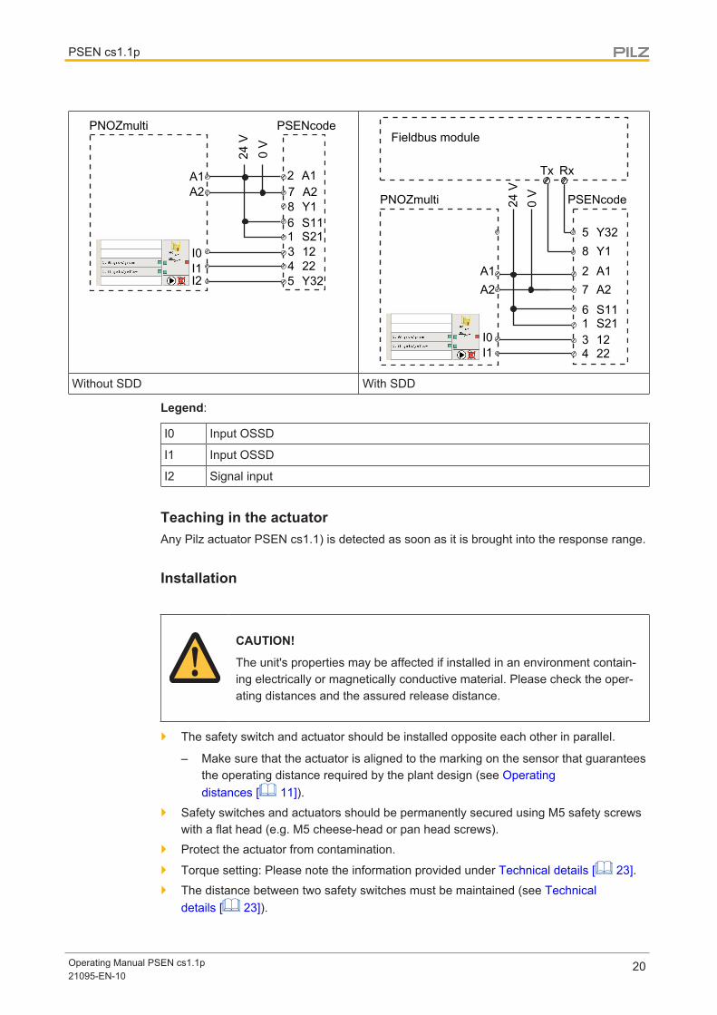
A1A2
I0I1
A1A2
Y32
Y1S11S211222
1
2
345
6
78
PNOZmulti
0 V
24 V
PSENcode
I2A1A2
I0I1
A1A2
Y32Y1
S11S211222
1
2
34
5
67
8
RxTx
PNOZmulti 0 V
24 V
PSENcode
Fieldbus module
Without SDD With SDD
Legend:
I0 Input OSSD
I1 Input OSSD
I2 Signal input
Teaching in the actuatorAny Pilz actuator PSEN cs1.1) is detected as soon as it is brought into the response range.
Installation
CAUTION!
The unit's properties may be affected if installed in an environment contain-ing electrically or magnetically conductive material. Please check the oper-ating distances and the assured release distance.
} The safety switch and actuator should be installed opposite each other in parallel.
– Make sure that the actuator is aligned to the marking on the sensor that guaranteesthe operating distance required by the plant design (see Operatingdistances [ 11]).
} Safety switches and actuators should be permanently secured using M5 safety screwswith a flat head (e.g. M5 cheese-head or pan head screws).
} Protect the actuator from contamination.
} Torque setting: Please note the information provided under Technical details [ 23].
} The distance between two safety switches must be maintained (see Technicaldetails [ 23]).

PSEN cs1.1p
Operating Manual PSEN cs1.1p21095-EN-10
21
} Make sure that the safety switch and actuator cannot be used as an end stop.
} Please note the installation measures in accordance with EN ISO 14119 for a safetyswitch design 4 and with level of coding Low
} For simpler installation, the mounting brackets (see Order reference forAccessories [ 27]) can be used.
} If using angled connector plugs, note the defined angle of the cable routing.
CAUTION!Possible loss of the safety function by changing the release distance Sar
with non-flush installation
Installing the safety switch non-flush within electrically or magnetically con-ductive material, the value for the assured release distance Sar can change.
– Check the assured release distance Sar.
Procedure:
Fig.: Sensing faces on the sensor
1. Drill holes (for M5 screws) in the mounting surface to secure the actuator and sensor(see Dimensions in mm [ 23]).
2. Use a screw to fix the sensor to the mounting surface.
Make sure that the sensor marking that is be used for operation can be operated usingthe actuator from the right side.
3. Do not fully tighten the second screw on the safety switch.
4. Use a screw to fix the actuator to the mounting surface.
Make sure that the actuator with the printed side points towards the marking on thesensor.
5. Do not fully tighten the second screw on the actuator.
6. Align the safety switch and tighten the screws.
7. Align the actuator and tighten the screws.

PSEN cs1.1p
Operating Manual PSEN cs1.1p21095-EN-10
22
Adjustment} The stated operating distances (see Technical details [ 23]) only apply when the
safety switch and actuator are installed facing each other in parallel. Operating dis-tances may deviate if other arrangements are used.
} Note the maximum permitted lateral and vertical offset (see Operatingdistances [ 11] and Lateral and vertical offset [ 12]).
Operation
NOTICE
The safety function should be checked after initial commissioning and eachtime the plant/machine is changed. The safety functions may only bechecked by qualified personnel.
Status indicators:
} "Power / Fault" LED illuminates green: The unit is ready for operation
} "Safety Gate" LED lights up yellow: Actuator is within the response range
} "Input" LED lights up yellow: There is a high signal at both inputs
Fault indicator:} "Input" LED lights up yellow: The signal switches from high to low at one input, while a
high signal remains on the other input (partial operation).Remedy: Open both channels of the input circuit.
} "Power/Fault" LED lights up red: Error messageRemedy: Rectify fault and interrupt power supply.
Please note the different times for
} The switch-on delay after UB is applied
} The recovery time of the sensor and evaluation device.

PSEN cs1.1p
Operating Manual PSEN cs1.1p21095-EN-10
23
Dimensions in mm
Safety switch
5,1 1 61
45
72
21,5
74
20
5,5
30
40
20
Actuator
30
40
5,3
30
40
0,5
4
11
Technical details
GeneralApprovals CE, EAC (Eurasian), FCC, IC, TÜV, cULus ListedSensor's mode of operation TransponderCoding level in accordance with EN ISO 14119 LowDesign in accordance with EN ISO 14119 4Classification in accordance with EN 60947-5-3 PDDBPilz coding type CodedTransponderFrequency band 122 kHz - 128 kHzMax. transmitter output 7 dBm
PSEN cs1.1p
Operating Manual PSEN cs1.1p21095-EN-10
24
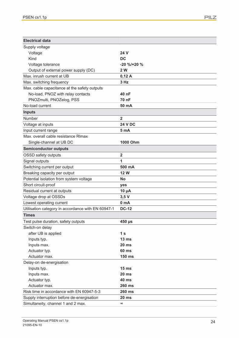
Electrical dataSupply voltage
Voltage 24 VKind DCVoltage tolerance -20 %/+20 %Output of external power supply (DC) 2 W
Max. inrush current at UB 0,12 AMax. switching frequency 3 HzMax. cable capacitance at the safety outputs
No-load, PNOZ with relay contacts 40 nFPNOZmulti, PNOZelog, PSS 70 nF
No-load current 50 mAInputsNumber 2Voltage at inputs 24 V DCInput current range 5 mAMax. overall cable resistance Rlmax
Single-channel at UB DC 1000 OhmSemiconductor outputsOSSD safety outputs 2Signal outputs 1Switching current per output 500 mABreaking capacity per output 12 WPotential isolation from system voltage NoShort circuit-proof yesResidual current at outputs 10 µAVoltage drop at OSSDs 3,5 VLowest operating current 0 mAUtilisation category in accordance with EN 60947-1 DC-12TimesTest pulse duration, safety outputs 450 µsSwitch-on delay
after UB is applied 1 sInputs typ. 13 msInputs max. 20 msActuator typ. 60 msActuator max. 150 ms
Delay-on de-energisationInputs typ. 15 msInputs max. 20 msActuator typ. 40 msActuator max. 260 ms
Risk time in accordance with EN 60947-5-3 260 msSupply interruption before de-energisation 20 msSimultaneity, channel 1 and 2 max. ∞

PSEN cs1.1p
Operating Manual PSEN cs1.1p21095-EN-10
25
Environmental dataAmbient temperature
In accordance with the standard EN 60068-2-14Temperature range -25 - 70 °C
Storage temperatureIn accordance with the standard EN 60068-2-1/-2
Climatic suitabilityIn accordance with the standard EN 60068-2-78Humidity 93 % r. h. at 40 °C
EMC EN 60947-5-3Vibration
In accordance with the standard EN 60947-5-2Frequency 10 - 55 HzAmplitude 1 mm
Shock stressIn accordance with the standard EN 60947-5-2Acceleration 30gDuration 11 ms
Airgap creepageOvervoltage category IIIPollution degree 3
Rated insulation voltage 75 VRated impulse withstand voltage 0,8 kVProtection type
Housing IP67Mechanical dataActuator 1 PSEN cs1.1Operating distances
Assured operating distance Sao 15 mmTypical operating distance So 21 mmAssured release distance Sar 40 mmTypical release distance Sr 32 mmRepetition accuracy switching distances 10 %Change of operating distance with temperaturechanges +-0,01mm/°CTyp. Hysteresis 3 mm
Min. distance between safety switches 400 mmSensor flush installation in accordance with EN60947-5-2 Yes, follow installation guidelinesConnection type M12, 8-pin male connectorMaterial
Top PBTMax. torque setting for fixing screws 1 Nm

PSEN cs1.1p
Operating Manual PSEN cs1.1p21095-EN-10
26
Mechanical dataDimensions
Height 75 mmWidth 40 mmDepth 40 mm
Actuator dimensionsHeight 11 mmWidth 40 mmDepth 40 mm
Weight of safety switch 130 gWeight of actuator 20 gWeight 150 g
Where standards are undated, the 2016-10 latest editions shall apply.
Safety characteristic data
NOTICE
You must comply with the safety-related characteristic data in order toachieve the required safety level for your plant/machine.
OperatingMode
EN ISO13849-1:2015
PL
EN ISO13849-1:2015
Category
EN 62061
SIL CL
EN 62061
PFHD [1/h]
IEC 61511
SIL
IEC 61511
PFD
EN ISO13849-1:2015
TM [year]2-ch. OSSD PL e Cat. 4 SIL CL 3 4,10E-09 – 1,10E-04 20
All the units used within a safety function must be considered when calculating the safetycharacteristic data.
INFORMATION
A safety function's SIL/PL values are not identical to the SIL/PL values ofthe units that are used and may be different. We recommend that you usethe PAScal software tool to calculate the safety function's SIL/PL values.

PSEN cs1.1p
Operating Manual PSEN cs1.1p21095-EN-10
27
Supplementary data
Radio approval
USA/Canada
FCC ID:
IC:
FCC/IC-Requirements: This product complies with Part 15 of the FCC Rules and with Industry Canada licence-exempt RSS standards. Operation is subject to the following two conditions: 1) this product may not cause harmful interference, and 2) this product must accept any interference received, including interference that may cause undesired operation. Changes or modifications made to this product not expressly approved by Pilz may void the FCC authorization to operate this equipment. NOTE: This equipment has been tested and found to comply with the limits for a Class A digital device, pursuant to Part 15 of the FCC Rules. These limits are designed to provide reasonable protection against harmful interference when the equipment is operated in a commercial environment. This equipment generates, uses, and can radiate radio frequency energy and, if not installed and used in accordance with the instruction manual, may cause harmful interference to radio communications. Operation of this equipment in a residential area is likely to cause harmful interference in which case the user will be required to correct the interference at his own expense. Le présent produit est conforme aux CNR d'Industrie Canada applicables aux appareils radio exempts de licence. L'exploitation est autorisée aux deux conditions suivantes: (1) le produit ne doit pas produire de brouillage, et (2) l'utilisateur de le produit doit accepter tout brouillage radioélectrique subi, même si le brouillage est susceptible d'en compromettre le fonctionnement.
VT8-PSENCS17482A-PSENCS1
Order reference
System
Product type Features Connection type Order no.
PSEN cs1.1p / PSEN cs1.1 Safety gate system, coded 8-pin M12 connector 540 000
PSEN cs1.1p (switch) Safety switch, coded 8-pin M12 connector 540 050
PSEN cs1.1 Actuator, coded 540 080
Accessories
Installation materials
Product type Features Order no.
PSEN bracket Mounting bracket 532 110
PSEN mag/cs bracketstraight
Mounting aid 532 111
PSEN screw M5x10 10pcs Safety screws made from stainless steel with one-way slot 540 311
PSEN screw M5x20 10pcs Safety screws made from stainless steel with one-way slot 540 312
PSEN cs1/2 bracket cablefix
Mechanical protection against defeat, protecting against unau-thorised cable disconnection or damage for safety switchesPSENcode cs1/2, PSENcode cs5/6 M12, PSENslock
532 112

PSEN cs1.1p
Operating Manual PSEN cs1.1p21095-EN-10
28
Cable
Product type Connection 1 Connection 2 Length Order no.
PSEN cable M12-8sf Straight, M12, 8-pin, socket Open cable 3 m 540 319
5 m 540 320
10 m 540 321
20 m 540 333
30 m 540 326
PSEN cable M12-8af Angled, M12, 8-pin, socket Open cable 3 m 540 322
5 m 540 323
10 m 540 324
30 m 540 325
PSEN cable M12-8sfM12-8sm
straight, M12, 8-pin, socket Straight, M12, 8-pin, pin 2 m 540 340
5 m 540 341
10 540 342
20 m 540 343
30 m 540 344
Series connection
Product type Connection X1 Connection X2Connec-tion X3 Order no.
PSEN Y junction M12SENSOR
M12, 8‑pin, pin M12, 8-pin, socket M12, 8-pin,socket
540 315
PSEN Y junction M12cable channel
M12, 8‑pin, pin M12, 8-pin, socket M12, 8-pin,socket
540 316
PSEN T junction M12 M12, 8-pin, socket M12, 8‑pin, pin M8,4‑pin, pin
540 331
PSEN Y junction M8-M12/M12 PIGTAIL
M12, 8-pin, socket M12, 8‑pin, pin M8,8‑pin,socket
540 337
PSEN Y junction M12-M12/M12 PIGTAIL
M12, 8-pin, socket M12, 8‑pin, pin M12, 8-pin,socket
540 338
PDP67 F 4 code Decentralised passive junction 773 603
PDP67 F 4 code VA Decentralised passive junction, V2A ring nut 773 613

PSEN cs1.1p
Operating Manual PSEN cs1.1p21095-EN-10
29
Safety Device Diagnostics
Product type Features Connection type Order no.
PSEN ix2 F4 code Interface for connectingmax. 4 PSEN safetysensors
Spring-loaded terminal 535 111
PSEN ix2 F8 code Interface for connectingmax. 8 PSEN safetysensors
Spring-loaded terminal 535 112
SDD ES ETH Fieldbus module Modbus/TCP for Safety Device Dia-gnostics
Spring-loaded terminal 540 130
SDD ES Profibus Fieldbus module Profibusfor Safety Device Dia-gnostics
Spring-loaded terminal 540 132
SDD ES Profinet Fieldbus module for SafetyDevice Diagnostics
Spring-loaded terminal 540 138
EC declaration of conformityThis product/these products meet the requirements of the directive 2006/42/EC for ma-chinery of the European Parliament and of the Council. The complete EC Declaration ofConformity is available on the Internet at www.pilz.com/downloads.Representative: Norbert Fröhlich, Pilz GmbH & Co. KG, Felix-Wankel-Str. 2, 73760 Ost-fildern, Germany
The Best of German Engineering
Partner of:
SupportTechnical support is available from Pilz round the clock.
Americas
Brazil
+55 11 97569-2804
Canada
+1 888-315-PILZ (315-7459)
Mexico
+52 55 5572 1300
USA (toll-free)
+1 877-PILZUSA (745-9872)
Asia
China
+86 21 60880878-216
Japan
+81 45 471-2281
South Korea
+82 31 450 0680
Australia
+61 3 95600621
Europe
Austria
+43 1 7986263-0
Belgium, Luxembourg
+32 9 3217575
France
+33 3 88104000
Germany
+49 711 3409-444
Ireland
+353 21 4804983
Italy, Malta
+39 0362 1826711
Scandinavia
+45 74436332
Spain
+34 938497433
Switzerland
+41 62 88979-30
The Netherlands
+31 347 320477
Turkey
+90 216 5775552
United Kingdom
+44 1536 462203
You can reach our
international hotline on:
+49 711 3409-444
CM
SE
®,
Ind
ura
NE
T p
®,
PA
S4
00
0®,
PA
Scal®
, P
AS
co
nfig
®,
Pilz
®,
PIT
®,
PLID
®,
PM
Cp
rim
o®,
PM
Cp
rote
go
®,
PM
Cte
nd
o®,
PM
D®,
PM
I®,
PN
OZ
®,
Prim
o®,
PS
EN
®,
PS
S®,
PV
IS®,
Safe
tyB
US
p®,
Safe
tyE
YE
®,
Safe
tyN
ET
p®,
TH
E S
PIR
IT O
F S
AFE
TY
® a
re r
eg
iste
red
and
pro
tecte
d t
rad
em
ark
s o
f P
ilz G
mb
H &
Co
. K
G in s
om
e c
ountr
ies.
We w
ould
po
int
out
that
pro
duct
featu
res m
ay v
ary
fro
m t
he d
eta
ils s
tate
d in t
his
do
cum
ent,
dep
end
ing
on t
he s
tatu
s a
t th
e t
ime o
f p
ub
licatio
n a
nd
the s
co
pe o
f th
e e
quip
ment.
We a
ccep
t no
resp
onsib
ility
fo
r th
e v
alid
ity,
accura
cy
and
entire
ty o
f th
e t
ext
and
gra
phic
s p
resente
d in t
his
info
rmatio
n.
Ple
ase c
onta
ct
our
Technic
al S
up
po
rt if
yo
u h
ave a
ny q
uestio
ns.
Pilz develops environmentally-friendly products using
ecological materials and energy-saving technologies.
Offices and production facilities are ecologically designed,
environmentally-aware and energy-saving. So Pilz offers
sustainability, plus the security of using energy-efficient
products and environmentally-friendly solutions.
Pilz GmbH & Co. KG
Felix-Wankel-Straße 2
73760 Ostfildern, Germany
Tel.: +49 711 3409-0
Fax: +49 711 3409-133
www.pilz.com
20
0X
XX
X-E
N-0
X
0-0
-2-3
-000,
2017-0
0 P
rinte
d in
Germ
any
© P
ilz G
mb
H &
Co.
KG
, 2017
2109
5-E
N-1
0, 2
017-
04 P
rinte
d in
Ger
man
y©
Pilz
Gm
bH &
Co.
KG
, 201
5
Back cover
Recommended