Issue 1.00
Professional NMEA 0183 Multiplexer Install/User Manual
For all variants:PRO-MUX-1-RPRO-MUX-1-S
Issue 1.0

© 2018 Active Research LimitedPage 2
Important NoticesThe device to which this manual relates complies with the Electromagnetic Compatibility requirements according to EN60945. The unit should always be used in conjunction with appropriately approved, shielded cable and connectors as per NMEA 0400 to ensure compliance. A declaration of conformity is available for download at www.actisense.com.
If the device to which this manual relates is to be installed within five metres of a compass, please refer to the ‘Compass Safe Distance’ section in the ‘Technical Specifications’ table.
Trademarks and Registered TrademarksActisense® and the Actisense logo are registered trademarks of Active Research Limited (Ltd). All other trademarks are the property of their respective owners.
The NMEA® name and NMEA logo are copyright held by the NMEA. All uses in this manual are by permission and no claim on the right to the NMEA name or logo are made in this manual.
Fair Use StatementThe contents of this manual may not be transferred or copied without the express written permission of Active Research Ltd. Copyright © 2018 Active Research Ltd. All rights reserved.
Technical AccuracyTo the best of our knowledge the information contained in this document was correct at the time it was produced. Active Research Ltd cannot accept liability for any inaccuracies or omissions. The products described in this manual and the specifications thereof may be changed without prior notice. Active Research Ltd cannot accept any liability for differences between the product and this document. To check for updated information and specifications please check www.actisense.com.
Active Research Ltd will not be liable for infringement of copyright, industrial property rights, or other rights of a third party caused by the use of information or drawings described in this manual.
Product RegistrationPlease register your product via the online form at actisense.com/product-registration/.
Your product package includes a unit serial number. The serial number is six digits long and can be found below the barcode on the label. Your registration will assist Actisense Support to link your product to your details, simplifying any future assistance you may require.
Product GuaranteeAll Actisense products are provided with a 3 year guarantee as standard. To activate the 5-year guarantee offered with this product please complete product registration either online (See ‘Product Registration’ section above) or by completing and returning the warranty card supplied in the box with the product. If you suspect that the unit is faulty please refer to the Troubleshooting Section of the User Manual before contacting support.
It is a requirement of the guarantee that all installations of electronic equipment follow the NMEA 0400 specification. Any connection to a battery or power supply must meet the mandatory essential safety requirements that may be imposed by local regulatory agencies.
Actisense products are intended for use in a marine environment, primarily for below deck use. If a product is to be used in a more severe environment, such use may be considered misuse under the Active Research Ltd guarantee.
Product DisposalPlease dispose of this product in accordance with the WEEE Directive. The product should be taken to a registered establishment for the disposal of electronic equipment.
© 2018 Active Research Limited
Professional NMEA 0183 Intelligent Multiplexer - PRO-MUX-1
Page 3
ContentsImportant Notices ........................................................................................................................... 2Trademarks and Registered Trademarks ........................................................................................................2Fair Use Statement..........................................................................................................................................2Technical Accuracy ..........................................................................................................................................2Product Registration ........................................................................................................................................2Product Guarantee ..........................................................................................................................................2Product Disposal .............................................................................................................................................2
Installation Warnings ..................................................................................................................... 4Warning 1: Accuracy ....................................................................................................................................................... 4Warning 2: Installation and Operation .............................................................................................................4Warning 3: Installation Code of Practice .........................................................................................................4Warning 4: Mounting Requirements ................................................................................................................4Software Updates ............................................................................................................................................4
PRO-MUX-1 Intro & Features ......................................................................................................... 5
Before getting started .................................................................................................................... 6
Terminals ......................................................................................................................................... 6
Connections .................................................................................................................................... 6Power Supply ..................................................................................................................................................6NMEA 0183 Talker and Listener Designations ................................................................................................7Connecting to NMEA Devices .........................................................................................................................7OPTO Inputs ....................................................................................................................................................7RF Ground Connection....................................................................................................................................7ISO-Drive Outputs ...........................................................................................................................................7Serial ...............................................................................................................................................................8Ethernet ...........................................................................................................................................................8Alarm ...............................................................................................................................................................8
Mounting the PRO-MUX-1 .............................................................................................................. 9DIN Rail Mounting ...........................................................................................................................................9Bulkhead Mounting ..........................................................................................................................................9
Web Browser Configuration Tool ................................................................................................ 10
Standard Ethernet networks........................................................................................................ 10
Direct connections or basic Ethernet networks ........................................................................ 11
Troubleshooting Guide ................................................................................................................ 12
Technical Support and the Returns Procedure ......................................................................... 13

© 2018 Active Research LimitedPage 4
Installation Warnings
All warnings and notices must be followed to ensure the correct operation of the PRO-MUX-1. Incorrect installation may invalidate the guarantee.
It is highly recommended that all of the installation instructions are read before commencing the installation.There are important warnings and notes throughout the manual that should be considered before the installation is attempted.
Warning 1: Accuracy The Actisense PRO-MUX-1 is designed to accurately transfer data from input to output. When the PRO-MUX-1 is in a Basic Mode no data integrity checking is performed, therefore any incomplete, inaccurate or corrupt data received on a PRO-MUX-1 input will be duplicated to the PRO-MUX-1 outputs. In contrast, PRO-MUX-1 Smart Modes do use the sentence checksum (if available) to remove incomplete and corrupted data, however, the accuracy of the data fields in a valid sentence still remains the responsibility of the NMEA Talker that generated the data.
Warning 2: Installation and OperationThis product must be installed and operated in accordance with the instructions provided. Failure to do so could result in personal injury, damage to your boat and/or poor product performance.
Warning 3: Installation Code of PracticeWhen wiring the power supply to the PRO-MUX-1 ensure the isolation switch is off. Wiring the PRO-MUX-1 while the connection is live may damage the PRO-MUX-1 and is in breach of the guarantee. Any connection to a battery or power supply must meet the mandatory essential safety requirements that may be imposed by local regulatory agencies. All wiring should be in accordance with the requirements of the NMEA 0400 installation specification.
Warning 4: Mounting RequirementsSelect a flat location to mount the PRO-MUX-1. Mounting on a contoured surface may cause damage to the case. Do not mount the PRO-MUX-1 while the device is powered, or the cable harness is connected. Note that the connectors are pluggable for easy disconnection when mounting or removing the PRO-MUX-1.
Software UpdatesThe PRO-MUX-1 units have built-in firmware which is held in flash memory, allowing quick and easy upgrades using the latest Actisense Toolkit. It is highly recommended that the firmware is kept up to date in the PRO-MUX-1. The firmware version installed in the PRO-MUX-1 can be viewed on the web based Configuration Tool ‘Home’ page, in the ‘Main Application’ section. Details of the latest PRO-MUX-1 firmware version released can be viewed on the Actisense website.

© 2018 Active Research Limited
Professional NMEA 0183 Intelligent Multiplexer - PRO-MUX-1
Page 5
The Actisense® Professional NMEA 0183 Multiplexer (PRO-MUX-1) is a robust and highly flexible platform that cures many interconnectivity headaches.
The PRO-MUX-1 is reliable, robust and provides industry leading isolation on all inputs and outputs as standard, so that connected devices safely avoid hazardous ground loops, the number 1 cause of product failure in NMEA 0183 networks.
The eight NMEA 0183 inputs can be routed to any of the six NMEA 0183 outputs, providing a highly customisable network. A bi-directional serial port and an Ethernet port allow for simple configuration and diagnostics using Actisense software.
The configuration tool is accessible via any popular web browser (using the Ethernet port) so there are no PC operating system compatibility issues to contend with. Using the web based configuration tool will allow the user to finely tune the exact data available on each output. The default setup is for all data to go to all outputs.
2-part pluggable connectors on the PRO-MUX-1 (screw or screwless terminals available) mean that new devices can easily be installed without the need to remove the PRO-MUX-1 from its mounted location. A professional DIN rail mounting mechanism keeps the PRO-MUX-1 secure in high vibration environments. Helpful LEDs indicate power, data in, data out and the alarm status to aid diagnostics.
• Ethernet port – for configuration, diagnostics and sharing NMEA 0183 data• 8 OPTO-Isolated NMEA 0183 inputs• 6 ISO-Drive NMEA 0183 outputs• Advanced Data Filtering/Routing• Configurable Input and output baud rates• Serial port – for configuration, diagnostics or as an additional NMEA 0183 input/output. • Free firmware updates make the device future-proof• Alarm output relay (N/O and N/C contacts available) • Mode inputs to provide manual selection of operational mode• Diagnostic LEDs on all inputs and outputs• Alarm status LED• Mode LED• Bi-colour status LED • DIN rail or Panel mountable• Pluggable connectors for quick and easy installation
PRO-MUX-1 Intro & Features
© 2018 Active Research LimitedPage 6
Before getting startedThe wire colours used in this manual are in accordance with the NMEA 0183 specification (v.4.10, June 2014) and are for illustration purposes only. Please ensure you check the wiring colours in the installation instructions for the devices you wish to interface to the PRO-MUX-1.
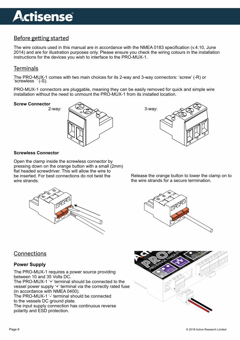
TerminalsThe PRO-MUX-1 comes with two main choices for its 2-way and 3-way connectors: ‘screw’ (-R) or ‘screwless ’ (-S).
PRO-MUX-1 connectors are pluggable, meaning they can be easily removed for quick and simple wire installation without the need to unmount the PRO-MUX-1 from its installed location.
Screw Connector 2-way: 3-way:
Screwless Connector
Open the clamp inside the screwless connector by pressing down on the orange button with a small (2mm) flat headed screwdriver. This will allow the wire to be inserted. For best connections do not twist the wire strands.
Connections
Power SupplyThe PRO-MUX-1 requires a power source providing between 10 and 35 Volts DC. The PRO-MUX-1 ‘+’ terminal should be connected to the vessel power supply ‘+’ terminal via the correctly rated fuse (in accordance with NMEA 0400).The PRO-MUX-1 ‘-’ terminal should be connected to the vessels DC ground plate.The input supply connection has continuous reverse polarity and ESD protection.
Release the orange button to lower the clamp on to the wire strands for a secure termination.

© 2018 Active Research Limited
Professional NMEA 0183 Intelligent Multiplexer - PRO-MUX-1
Page 7
NMEA 0183 Talker and Listener Designations
The NMEA have updated the NMEA 0183 specification to ensure a consistent naming convention is used for labelling ports. The designation follows the same rules as used for Rx and Tx labelling but uses Talker and Listener instead. The input / receiving (Rx) port will be labelled as a ‘Listener’ port. The output / transmitting (Tx) port will be labelled as a ‘Talker’ port. When a port is labelled ‘Listener’ it is an input and when it is labelled ‘Talker’ it is an output.
Connecting to NMEA Devices
The ‘A/+’ and ‘B/-’ of the NMEA 0183 device should be matched to the ‘A’ and ‘B’ on the PRO-MUX-1. If the NMEA 0183 device has a ground (GND) wire (and no ‘B/-’ wire), simply connect this to ‘B’ on the PRO-MUX-1.
OPTO InputsConnect the NMEA 0183 Talker to the PRO-MUX-1 Listener terminals as shown in the diagram.
RF Ground ConnectionThe shield from each Listener should be connected to the terminal on the PRO-MUX-1 ‘Isolated Talkers’ ports. All terminals are connected internally and form a common bonding point at the RF ground stud.
The RF ground stud should be connected to the vessels RF ground plate using a minimum conductor size of 8 AWG (10mm2) in accordance with NMEA 0400, (in version 3.1, this is in section 3.2).
ISO-Drive OutputsConnect the NMEA 0183 Listener to the PRO-MUX-1 Talker terminals as shown in the diagram. Connect the shield/drain wire of each Listener to the terminal.
© 2018 Active Research LimitedPage 8
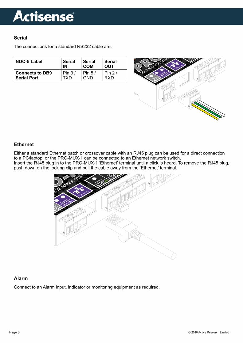
SerialThe connections for a standard RS232 cable are:
EthernetEither a standard Ethernet patch or crossover cable with an RJ45 plug can be used for a direct connection to a PC/laptop, or the PRO-MUX-1 can be connected to an Ethernet network switch.Insert the RJ45 plug in to the PRO-MUX-1 ‘Ethernet’ terminal until a click is heard. To remove the RJ45 plug, push down on the locking clip and pull the cable away from the ‘Ethernet’ terminal.
AlarmConnect to an Alarm input, indicator or monitoring equipment as required.
NDC-5 Label Serial IN
Serial COM
Serial OUT
Connects to DB9 Serial Port
Pin 3 / TXD
Pin 5 / GND
Pin 2 / RXD

© 2018 Active Research Limited
Professional NMEA 0183 Intelligent Multiplexer - PRO-MUX-1
Page 9
Mounting the PRO-MUX-1 DIN Rail MountingInstall the DIN rail in the desired location. Fully retract the black securing latch in to the down position.Attach the PRO-MUX-1 to the DIN rail as shown in the diagrams below. Ensure the PRO-MUX-1 sits flush against the DIN rail, then push the securing latch back in to position to hold the PRO-MUX-1 in place.
Bulkhead MountingActisense recommends the PRO-MUX-1 is installed using the DIN rail supplied for the most secure installation. However, the PRO-MUX-1 can be secured to a bulkhead using the two screw catches on the reverse of the PRO-MUX-1 shown in the diagram below. Two screws must be used 89.4mm apart and horizontally aligned.
Latch down
© 2018 Active Research LimitedPage 10
Web Browser Configuration Tool
The Configuration Tool for the PRO-MUX-1 is built-in and can be accessed via the Ethernet connection. As the Configuration Tool is web based it is compatible with all popular web browsers and Operating Systems. An internet connection is not required to access the Configuration Tool.
The default page displayed is the PRO-MUX-1 Configuration Tool ‘Home’ page. We strongly suggest bookmarking the ‘Home’ page in your web browser to allow quick and easy future access.
To access any of the PRO-MUX-1 setup pages, the user is required to log-in. This prevents unauthorised user access from modifying the PRO-MUX-1 configuration. The factory default log-in is “admin” for username and “admin” for password.
All modifications to the PRO-MUX-1 settings, including any user defined ‘User Modes’ are automatically saved inside the PRO-MUX-1.
Standard Ethernet networksIf the PRO-MUX-1 is connected to an Ethernet network containing both DHCP and DNS servers, launch any popular web browser and enter ‘http://promux-xxxxxx’ into the address bar (replacing ‘xxxxxx’ with the actual product’s serial number). It is important to include the ‘http://’ section of this address. If it is missing, the browser will conduct a web search.
© 2018 Active Research Limited
Professional NMEA 0183 Intelligent Multiplexer - PRO-MUX-1
Page 11
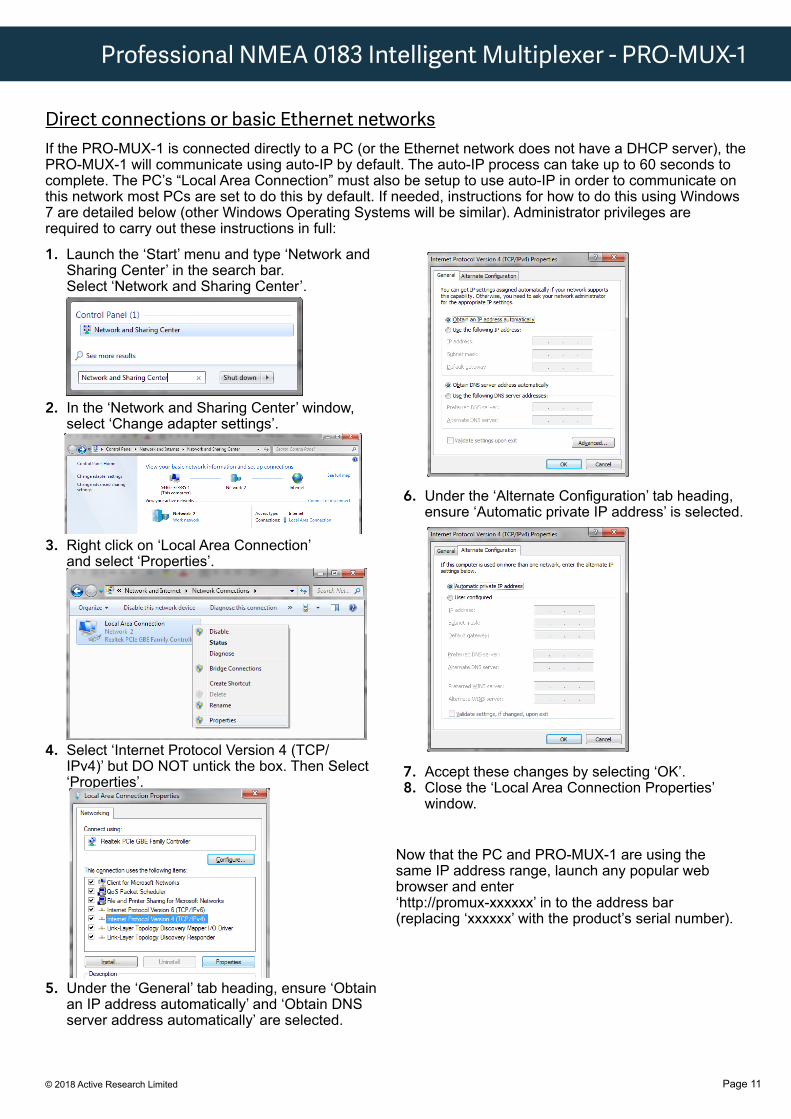
1. Launch the ‘Start’ menu and type ‘Network and Sharing Center’ in the search bar. Select ‘Network and Sharing Center’.
2. In the ‘Network and Sharing Center’ window, select ‘Change adapter settings’.
3. Right click on ‘Local Area Connection’ and select ‘Properties’.
4. Select ‘Internet Protocol Version 4 (TCP/IPv4)’ but DO NOT untick the box. Then Select ‘Properties’.
5. Under the ‘General’ tab heading, ensure ‘Obtain an IP address automatically’ and ‘Obtain DNS server address automatically’ are selected.
Now that the PC and PRO-MUX-1 are using the same IP address range, launch any popular web browser and enter ‘http://promux-xxxxxx’ in to the address bar (replacing ‘xxxxxx’ with the product’s serial number).
Direct connections or basic Ethernet networksIf the PRO-MUX-1 is connected directly to a PC (or the Ethernet network does not have a DHCP server), the PRO-MUX-1 will communicate using auto-IP by default. The auto-IP process can take up to 60 seconds to complete. The PC’s “Local Area Connection” must also be setup to use auto-IP in order to communicate on this network most PCs are set to do this by default. If needed, instructions for how to do this using Windows 7 are detailed below (other Windows Operating Systems will be similar). Administrator privileges are required to carry out these instructions in full:
6. Under the ‘Alternate Configuration’ tab heading, ensure ‘Automatic private IP address’ is selected.
7. Accept these changes by selecting ‘OK’.8. Close the ‘Local Area Connection Properties’
window.
© 2018 Active Research LimitedPage 12
Troubleshooting Guide
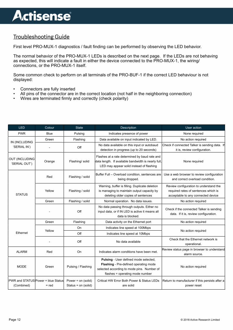
First level PRO-MUX-1 diagnostics / fault finding can be performed by observing the LED behavior.
The normal behavior of the PRO-MUX-1 LEDs is described on the next page. If the LEDs are not behaving as expected, this will indicate a fault in either the device connected to the PRO-MUX-1, the wiring/connections, or the PRO-MUX-1 itself.
Some common check to perform on all terminals of the PRO-BUF-1 if the correct LED behaviour is not displayed:
• Connectors are fully inserted• All pins of the connector are in the correct location (not half in the neighboring connection)• Wires are terminated firmly and correctly (check polarity)
LED Colour State Description User action
PWR Blue Pulsing Indicates presence of power None required
IN (INCLUDING ‘SERIAL IN’)
Green Flashing Data available on input indicated by LED. No action required
- OffNo data available on this input or autobaud
detection in progress (up to 20 seconds)Check if connected Talker is sending data. If
it is, review configuration.
OUT (INCLUDING ‘SERIAL OUT’)
Orange Flashing/ solidFlashes at a rate determined by baud rate and
data length. If available bandwidth is nearly full, LED may appear solid instead of flashing
None required
STATUS
Red Flashing / solidBuffer Full – Overload condition, sentences are
being dropped.Use a web browser to review configuration
and correct overload condition.
Yellow Flashing / solidWarning, buffer is filling. Duplicate deletion is managing to maintain output capacity by
deleting older copies of sentences
Review configuration to understand the required rates of sentences which is acceptable to any connected device
Green Flashing / solid Normal operation. No data issues. No action required
- OffNo data passing through outputs. Either no input data, or if IN LED is active it means all
data is blocked.
Check if the connected Talker is sending data. If it is, review configuration.
Ethernet
Green Flashing Data activity on the Ethernet port No action required
YellowOn Indicates line speed at 100Mbps
No action requiredOff Indicates line speed at 10Mbps
- Off No data available Check that the Ethernet network is
operational.
ALARM Red On Indicates alarm conditions have been met.Review status page in browser to understand
alarm source.
MODE Green Pulsing / Flashing
Pulsing - User defined mode selected, Flashing - Pre-defined operating mode
selected according to mode pins. Number of flashes = operating mode number
No action required
PWR and STATUS (Combined)
Power = blue Status = red
Power = on (solid) Status = on (solid)
Critical HW Error Both Power & Status LEDs are solid
Return to manufacturer if this persists after a power reset

© 2018 Active Research Limited
Professional NMEA 0183 Intelligent Multiplexer - PRO-MUX-1
Page 13
Technical Support and the Returns ProcedureAll installation instructions and any warnings contained in this manual must be followed before contacting Actisense technical support. If the troubleshooting guide did not help resolve the problem and an error persists, please contact Actisense Technical Support to help trace the issue before considering the return of the product.
If the Actisense support engineer concludes that the PRO-MUX-1 unit should be returned to Actisense, a ‘Return Merchandise Authorisation’ (RMA) number will be issued by the support engineer.
The RMA number must be clearly visible on both the external packaging and any documentation returned with the product. Any returns sent without an RMA Number will incur a delay in being processed and a possible charge. Any cables originally supplied with the product are to be included in the returned box.
© 2018 Active Research LimitedPage 14
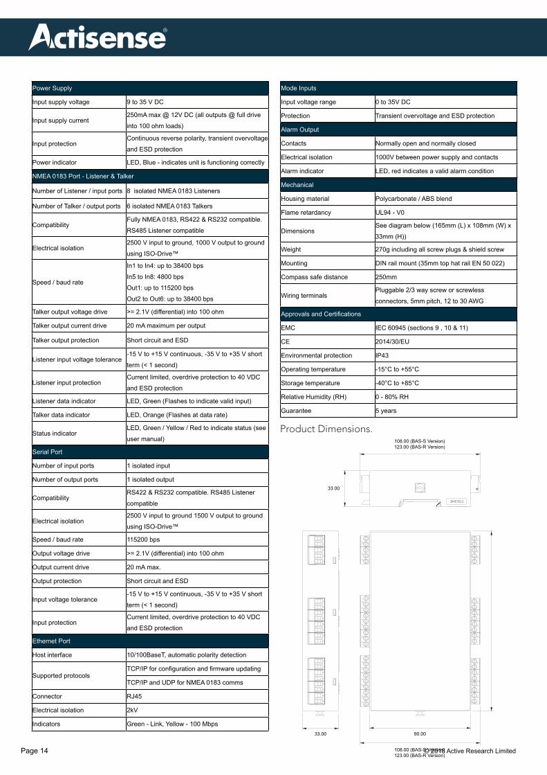
Product Dimensions.
33.00 90.00
33.00
108.00 (BAS-S Version)123.00 (BAS-R Version)
108.00 (BAS-S Version)123.00 (BAS-R Version)
Power Supply
Input supply voltage 9 to 35 V DC
Input supply current250mA max @ 12V DC (all outputs @ full drive
into 100 ohm loads)
Input protectionContinuous reverse polarity, transient overvoltage
and ESD protection
Power indicator LED, Blue - indicates unit is functioning correctly
NMEA 0183 Port - Listener & Talker
Number of Listener / input ports 8 isolated NMEA 0183 Listeners
Number of Talker / output ports 6 isolated NMEA 0183 Talkers
CompatibilityFully NMEA 0183, RS422 & RS232 compatible.
RS485 Listener compatible
Electrical isolation2500 V input to ground, 1000 V output to ground
using ISO-Drive™
Speed / baud rate
In1 to In4: up to 38400 bps
In5 to In8: 4800 bps
Out1: up to 115200 bps
Out2 to Out6: up to 38400 bps
Talker output voltage drive >= 2.1V (differential) into 100 ohm
Talker output current drive 20 mA maximum per output
Talker output protection Short circuit and ESD
Listener input voltage tolerance-15 V to +15 V continuous, -35 V to +35 V short
term (< 1 second)
Listener input protectionCurrent limited, overdrive protection to 40 VDC
and ESD protection
Listener data indicator LED, Green (Flashes to indicate valid input)
Talker data indicator LED, Orange (Flashes at data rate)
Status indicatorLED, Green / Yellow / Red to indicate status (see
user manual)
Serial Port
Number of input ports 1 isolated input
Number of output ports 1 isolated output
CompatibilityRS422 & RS232 compatible. RS485 Listener
compatible
Electrical isolation2500 V input to ground 1500 V output to ground
using ISO-Drive™
Speed / baud rate 115200 bps
Output voltage drive >= 2.1V (differential) into 100 ohm
Output current drive 20 mA max.
Output protection Short circuit and ESD
Input voltage tolerance-15 V to +15 V continuous, -35 V to +35 V short
term (< 1 second)
Input protectionCurrent limited, overdrive protection to 40 VDC
and ESD protection
Ethernet Port
Host interface 10/100BaseT, automatic polarity detection
Supported protocolsTCP/IP for configuration and firmware updating
TCP/IP and UDP for NMEA 0183 comms
Connector RJ45
Electrical isolation 2kV
Indicators Green - Link, Yellow - 100 Mbps
Mode Inputs
Input voltage range 0 to 35V DC
Protection Transient overvoltage and ESD protection
Alarm Output
Contacts Normally open and normally closed
Electrical isolation 1000V between power supply and contacts
Alarm indicator LED, red indicates a valid alarm condition
Mechanical
Housing material Polycarbonate / ABS blend
Flame retardancy UL94 - V0
DimensionsSee diagram below (165mm (L) x 108mm (W) x
33mm (H))
Weight 270g including all screw plugs & shield screw
Mounting DIN rail mount (35mm top hat rail EN 50 022)
Compass safe distance 250mm
Wiring terminalsPluggable 2/3 way screw or screwless
connectors, 5mm pitch, 12 to 30 AWG
Approvals and Certifications
EMC IEC 60945 (sections 9 , 10 & 11)
CE 2014/30/EU
Environmental protection IP43
Operating temperature -15°C to +55°C
Storage temperature -40°C to +85°C
Relative Humidity (RH) 0 - 80% RH
Guarantee 5 years

© 2018 Active Research Limited
Professional NMEA 0183 Intelligent Multiplexer - PRO-MUX-1
Page 15

© 2018 Active Research LimitedPage 16
®
21 Harwell Road Poole DorsetUK, BH17 0GE
Tel: +44 (0)1202 746682Email: [email protected]: actisense.com
Product Code Description
PRO-MUX-1-BAS-R Standard configuration with pluggable screw terminals
PRO-MUX-1-BAS-S Standard configuration with pluggable screwless terminals
Recommended