Kestrel Aluminium Systems Limited
Product Manual Section 7Low Rise Curtain Walling - Fabrication
Manual Version 23.0.1
© Kestrel Aluminium Systems Low Rise Curtain Walling
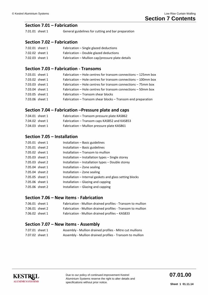
Section 7 Contents
Due to our policy of continued improvement Kestrel
Aluminium Systems reserve the right to alter details and
specifications without prior notice.
07.01.00
Sheet 1 01.11.14
Section 7.01 – Fabrication 7.01.01 sheet 1 General guidelines for cutting and bar preparation
Section 7.02 – Fabrication 7.02.01 sheet 1 Fabrication – Single glazed deductions
7.02.02 sheet 1 Fabrication – Double glazed deductions
7.02.03 sheet 1 Fabrication – Mullion cap/pressure plate details
Section 7.03 – Fabrication - Transoms 7.03.01 sheet 1 Fabrication – Hole centres for transom connections – 125mm box
7.03.02 sheet 1 Fabrication – Hole centres for transom connections – 100mm box
7.03.03 sheet 1 Fabrication – Hole centres for transom connections – 75mm box
7.03.04 sheet 1 Fabrication – Hole centres for transom connections – 50mm box
7.03.05 sheet 1 Fabrication – Transom shear blocks
7.03.06 sheet 1 Fabrication – Transom shear blocks – Transom end preparation
Section 7.04 – Fabrication –Pressure plate and caps 7.04.01 sheet 1 Fabrication – Transom pressure plate KAS862
7.04.02 sheet 1 Fabrication – Transom caps KAS852 and KAS853
7.04.03 sheet 1 Fabrication – Mullion pressure plate KAS861
Section 7.05 – Installation 7.05.01 sheet 1 Installation – Basic guidelines
7.05.01 sheet 2 Installation – Basic guidelines
7.05.02 sheet 1 Installation – Transom to mullion
7.05.03 sheet 1 Installation – Installation types – Single storey
7.05.03 sheet 2 Installation – Installation types – Double storey
7.05.04 sheet 1 Installation – Zone sealing
7.05.04 sheet 2 Installation – Zone sealing
7.05.05 sheet 1 Installation – Internal gaskets and glass setting blocks
7.05.06 sheet 1 Installation – Glazing and capping
7.05.06 sheet 2 Installation – Glazing and capping
Section 7.06 – New items - Fabrication 7.06.01 sheet 1 Fabrication - Mullion drained profiles - Transom to mullion
7.06.01 sheet 2 Fabrication - Mullion drained profiles - Transom to mullion
7.06.02 sheet 1 Fabrication - Mullion drained profiles – KAS833
Section 7.07 – New items - Assembly 7.07.01 sheet 1 Assembly - Mullion drained profiles - Mitre cut mullions
7.07.02 sheet 1 Assembly - Mullion drained profiles - Transom to mullion

Low Rise Curtain Walling
KESTRELALUMINIUM SYSTEMS
7.01.0101.10.08Sheet 1
Kestrel Aluminium Systems©
Due to our policy of continued improvement Kestrel Aluminium Systems reserve the right to alter details and specifications without prior notice.
General guidelines for cutting and bar preparation:
For further reading on cutting, preparation and workmanship please refer to BS 8118: Part 2: 1991.
Storage and transportation:
Store aluminium in a dry place, clear of the ground. Avoid contact with other metals and with materials such as cement and damp timber.
Protect aluminium extrusion surfaces with low tack removable tapes while danger of damage exists. Pack aluminium during transportation to avoid mechanical damage, abrasion and contact by agents liable to cause surface corrosion or staining.
Fabrication tolerance:
See corresponding sheets for each section type
Marking out:
Fine scribing lines must not be used on critically stressed ares of thin material. Where subsequent welding is involved paint, chalk, graphite or other marking materials likely to contaminate must not be used.
Cutting:
Cutting can be by circular saw or band saw and both must have a tooth form and pitch to suite the thickness of the material to be cut. Cut edges should be smooth, square and free from burrs, distortion and other irregularities. Care must be taken to avoid the use of tools contaminated by other metals, particulary copper or brass. Great care must be taken when working with mitred end cuts to avoid impact damage to ends (ideally bars should not be stored or transported vertically without corner protection).
Drilling, punching and preparation:
Holes can be made by either drilling, drilling and reaming or by punching. Drill holes should be smooth and free from burrs, distortion and other irregularities. Drainage slots must be of the correct diameter and length and positioned correctly. At all times prepared bars should be free from general debris and cutting/drilling swarf.
Assembly:
All joint surfaces should be free of dirt,grease and cutting/drilling debris. All joints shall be sealed against the entry of water by use of a high quality silicone sealant. NB Small gap joint sealant is NOT to be used on painted material - only anodised or mill finish profile. Be careful not to handle or transport frames in such a way as to disturb or open joints by excessive movement or bending of frames etc.
See separate document for installation guidelines
Fabrication - Guidelines for cutting and prepping
Low Rise Curtain Walling
KESTRELALUMINIUM SYSTEMS
7.02.0101.05.11Sheet 1
Kestrel Aluminium Systems©
Due to our policy of continued improvement Kestrel Aluminium Systems reserve the right to alter details and specifications without prior notice.
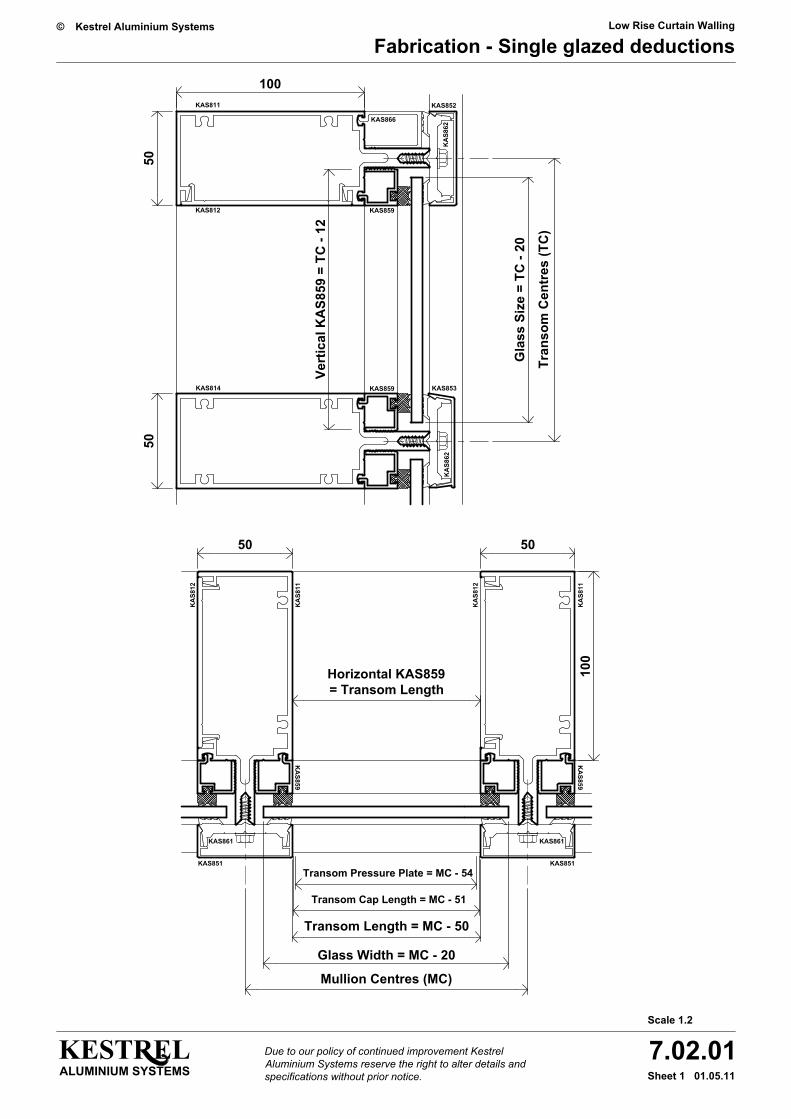
Fabrication - Single glazed deductions
KAS866
Horizontal KAS859= Transom Length
KAS859
KAS859
Transom Cap Length = MC - 51
Transom Pressure Plate = MC - 54
Mullion Centres (MC)
Glass Width = MC - 20
Transom Length = MC - 50
50
KAS851
KAS861
KA
S812
KA
S859
KA
S811
Vert
ical
KA
S859
= T
C -
12
50
KAS814
50
KAS812
100KAS811
50
KA
S812
100
KA
S859
KAS861
KAS851
KA
S811
Tran
som
Cen
tres
(TC
)
Gla
ss S
ize
= TC
- 20
KAS853
KA
S862
KAS852
KA
S862
Scale 1.2

Low Rise Curtain Walling
KESTRELALUMINIUM SYSTEMS
7.02.0201.10.08Sheet 1
Kestrel Aluminium Systems©
Due to our policy of continued improvement Kestrel Aluminium Systems reserve the right to alter details and specifications without prior notice.
Fabrication - Double glazed deductions
Scale 1.2
KAS866
Transom Cap Length = MC - 51
Transom Pressure Plate = MC - 54
Mullion Centres (MC)
Glass Width = MC - 20
Transom Length = MC - 50
50
KAS851
KAS861
KA
S812
KA
S811
50
KAS814
50
KAS812
100KAS811
50
KA
S812
100
KAS861
KAS851
KA
S811
Tran
som
Cen
tres
(TC
)
Gla
ss S
ize
= TC
- 20
KAS853
KA
S862
KAS852
KA
S862

Low Rise Curtain Walling
KESTRELALUMINIUM SYSTEMS
7.02.0301.10.08Sheet 1
Kestrel Aluminium Systems©
Due to our policy of continued improvement Kestrel Aluminium Systems reserve the right to alter details and specifications without prior notice.
Fabrication - Mullion cap/pressure plate details
Scale 1.2
Fixed through the Cap to the Mullion Nose Below
100
and Clamps the Unfixed Overlap of the Pressure Plate
This Allows Free Lineal Movement of the Caps AboveCrimped into Position in the Lower Cap OnlyPositioned to Overlap the Joint and Bonded or44.44 ( 1 " ) x 3.2 ( ") 50mm Long Aluminium Flat PlateKAS851 Mullion Cover Cap
This Allows Free Lineal Movement of the Plate Above
3/4 1/8
the Joint Only.
Out
side
4
KAS861 Mullion Pressure Plate
Flat Plate Positioned to Overlap the Joint and Screw31.76 ( 1 ") x 3.2 ( ") x 50mm Long Aluminium3/4 1/8
4
100
4
Important - No Pressure Cap Fixingto be within this 100mm Overlap Area
24
Low Rise Curtain Walling
KESTRELALUMINIUM SYSTEMS
7.03.0101.10.08Sheet 1
Kestrel Aluminium Systems©
Due to our policy of continued improvement Kestrel Aluminium Systems reserve the right to alter details and specifications without prior notice.
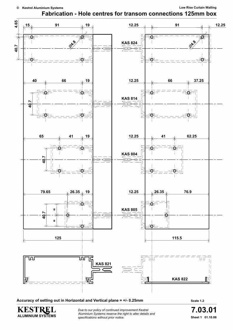
Fabrication - Hole centres for transom connections 125mm box
Scale 1.2
∅4.8∅4.8
15 91 194.65
40.7
12.25 12.2591
196640
40.7
6612.25 37.25
125 115.5
40.7
194165 12.25 41 62.25
40.7
==
1979.65 26.35 76.926.3512.25
KAS 824
KAS 814
KAS 804
KAS 805
KAS 822
KAS 821
Accuracy of setting out in Horizontal and Vertical plane = +/- 0.25mm
Low Rise Curtain Walling
KESTRELALUMINIUM SYSTEMS
7.03.0201.10.08Sheet 1
Kestrel Aluminium Systems©
Due to our policy of continued improvement Kestrel Aluminium Systems reserve the right to alter details and specifications without prior notice.
Fabrication - Hole centres for transom connections 100mm box
Scale 1.2
4.65
40.7
196615 6612.25 12.25
100 90.5
40.7
194140 12.25 41 37.25
40.7
==
1954.65 26.35 51.926.3512.25
KAS 814
KAS 804
KAS 805
KAS 812
KAS 811
∅4.8∅4.8
Accuracy of setting out in Horizontal and Vertical plane = +/- 0.25mm

Low Rise Curtain Walling
KESTRELALUMINIUM SYSTEMS
7.03.0301.10.08Sheet 1
Kestrel Aluminium Systems©
Due to our policy of continued improvement Kestrel Aluminium Systems reserve the right to alter details and specifications without prior notice.
Fabrication - Hole centres for transom connections 75mm box
Scale 1.2
4.65
40.7
194115 4112.25 12.25
75 65.5
40.7
==
1929.65 26.35 26.926.3512.25
KAS 804
KAS 805
KAS 802
KAS 801
∅4.8∅4.8∅4.8
1915 41 41
KAS 804
12.25 12.25
∅4.8
40.7
==
Accuracy of setting out in Horizontal and Vertical plane = +/- 0.25mm
Low Rise Curtain Walling
KESTRELALUMINIUM SYSTEMS
7.03.0401.10.08Sheet 1
Kestrel Aluminium Systems©
Due to our policy of continued improvement Kestrel Aluminium Systems reserve the right to alter details and specifications without prior notice.
Fabrication - Hole centres for transom connections 50mm box
Scale 1.2
9.5
50
31
==
KAS 805KAS 805
=
31
=
50
∅3.5
10 31.38 8.62
8.6231.3810
31.38 8.621031
==
20
10
KAS873D shear blockfixed with 3 No10 x 1 1/4" AB self tapping Pozi pan head screws KAS882
KAS873D shear blocks required for all transom to mullion connections
Accuracy of setting out in Horizontal and Vertical plane = +/- 0.25mm
Low Rise Curtain Walling
Fabrication - Transom shear blocks
KESTRELALUMINIUM SYSTEMS
7.03.0501.10.08Sheet 1
Kestrel Aluminium Systems©
Due to our policy of continued improvement Kestrel Aluminium Systems reserve the right to alter details and specifications without prior notice.
Scale 1.2
199115
∅6
M6 Threaded Inserts with 40mm hexagon Set Screws(Drill 9.1mm dia. Clear Holes for Threaded Inserts)
Where Shear Blocks are Required on One Side Only use
KAS872D
KAS871D
KAS870D KAS804
KAS814
KAS824
Note: Over Tightening May Cause the Profile to Distort.KAS889 M.06 Hexagon Bolts Nuts and Washers Where Shear Blocks are Required on Both Side use
See Drawing 7.03.04 sheet 1 for 50mm box (KAS805) shear blocks125
196640
6mm Ø holes on transom centre lines
125
100
75
KAS871D KAS871D
194165
20
50
Accuracy of setting out in Horizontal and Vertical plane = +/- 0.25mm
Low Rise Curtain Walling
Fabrication - Transom shear blocks
KESTRELALUMINIUM SYSTEMS
7.03.0601.10.08Sheet 1
Kestrel Aluminium Systems©
Due to our policy of continued improvement Kestrel Aluminium Systems reserve the right to alter details and specifications without prior notice.
Scale 1.2
KAS804
KAS814
KAS824
125
100
75
KAS805
50
Transom cut length
10.5
20
Drill and csk 2 x 4.5mm clearance holes for no 8
Repeat at each end of transom for screw fixing to shear blocks
20
10.5
10.5
2020
10.5
Csk Head Fixing ScrewTransom to Shear Block
KAS881

Low Rise Curtain Walling
Fabrication - Transom pressure plate KAS862
KESTRELALUMINIUM SYSTEMS
7.04.0101.10.08Sheet 1
Kestrel Aluminium Systems©
Due to our policy of continued improvement Kestrel Aluminium Systems reserve the right to alter details and specifications without prior notice.
should be a maximum of 50mm from the ends
an Additional Slot or Hole Should be includednot allow compliance with this Requirement then * When the centres of the Pre-Punched Slots do
Scale 1:1
10 x 6mm Pre-Punched SlottedFixing Holes @ 150mm Centres
Fixing Slots
Scale 1:1
Drainage Slots
30 x 6mm Pre-Punched SlottedDrainage Holes @ 300mm Ctrs.
The 10 x 6 Slots for the Pressure Plate Fixings
150
300 Drainage Slot Pitch
696 Pressure Plate Length
Example : 750 Mullion Centres
300 Drainage Slot Pitch
150
546 Pressure Plate Length
Example : 600 Mullion Centres
123
27
Fixing Slot Centres
103*
20
48
Fixing Slot Centres
48
Typical Examples KAS862
27
123
300 Drainage Slot Pitch
150
150
150
150
103 20
Scale 1:4
*
48
Scale 1:4
48
27

Low Rise Curtain Walling
Fabrication - Transom cover caps KAS852 & 853
KESTRELALUMINIUM SYSTEMS
7.04.0201.10.08Sheet 1
Kestrel Aluminium Systems©
Due to our policy of continued improvement Kestrel Aluminium Systems reserve the right to alter details and specifications without prior notice.
Mullion Centres from 1350mm upto 1950mm
Mullion Centres from 750mm upto 1350mm
Max. 600 Centres
Max. 600 Centres
30
Cap Length = Mullion Centres - 52mm
Cap Length = Mullion Centres - 52mm
30
75
75
26
30
26
3030
Max. 600 Centres Max. 600 Centres 75
Max. 600 Centres
30
75
26
26
30
Mullion Centres upto 750mm
Max. 600 Centres
Cap Length = Mullion Centres - 52mm
30
75
26
Typical ExamplesRout 6 x 30 Drainage Slots atPositions and Centres Shown
75
30
26
6
3 2
6
Out
er F
ace
75
View from Underside
Outer Face
KAS852 KAS853

Low Rise Curtain Walling
Fabrication - Mullion pressure plate KAS861
KESTRELALUMINIUM SYSTEMS
7.04.0301.10.08Sheet 1
Kestrel Aluminium Systems©
Due to our policy of continued improvement Kestrel Aluminium Systems reserve the right to alter details and specifications without prior notice.
KA
S861
Mul
lion
Pres
sure
Pla
te :
6.1
M S
tock
Len
gth
Scale 1:1
Fixing Slots
10 x 6mm Pre-Punched SlottedFixing Holes @ 150mm Centres
The 10 x 6 Slots for the Pressure Plate Fixings
an Additional Slot or Hole Should be includednot allow complience with this Requirement then * When the centres of the Pre-Punched Slots do
should be a maximum of 50mm from the ends
Fixi
ng S
lot C
entr
es
103
20
Scale 1:4
*15
0
10
6
Typical Examples
103
150
* 20
See drawing 7.02.03 sheet 1 for detail of both mullion pressure plate KAS861 and mullion cap KAS851 at mullion joint locations.
Low Rise Curtain Walling
Installation - Basic guidelines
KESTRELALUMINIUM SYSTEMS
7.05.0101.10.08Sheet 1
Kestrel Aluminium Systems©
Due to our policy of continued improvement Kestrel Aluminium Systems reserve the right to alter details and specifications without prior notice.
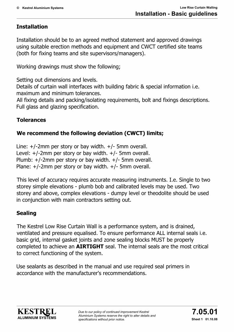
Installation
Installation should be to an agreed method statement and approved drawings using suitable erection methods and equipment and CWCT certified site teams (both for fixing teams and site supervisors/managers).
Working drawings must show the following;
Setting out dimensions and levels.Details of curtain wall interfaces with building fabric & special information i.e. maximum and minimum tolerances.All fixing details and packing/isolating requirements, bolt and fixings descriptions.Full glass and glazing specification.
Tolerances
We recommend the following deviation (CWCT) limits;
Line: +/-2mm per story or bay width. +/- 5mm overall.Level: +/-2mm per story or bay width. +/- 5mm overall.Plumb: +/-2mm per story or bay width. +/- 5mm overall.Plane: +/-2mm per story or bay width. +/- 5mm overall.
This level of accuracy requires accurate measuring instruments. I.e. Single to two storey simple elevations - plumb bob and calibrated levels may be used. Two storey and above, complex elevations - dumpy level or theodolite should be used in conjunction with main contractors setting out.
Sealing
The Kestrel Low Rise Curtain Wall is a performance system, and is drained, ventilated and pressure equalised. To ensure performance ALL internal seals i.e. basic grid, internal gasket joints and zone sealing blocks MUST be properly completed to achieve an AIRTIGHT seal. The internal seals are the most critical to correct functioning of the system.
Use sealants as described in the manual and use required seal primers in accordance with the manufacturer's recommendations.
Low Rise Curtain Walling
Installation - Basic guidelines
KESTRELALUMINIUM SYSTEMS
7.05.0101.10.08Sheet 2
Kestrel Aluminium Systems©
Due to our policy of continued improvement Kestrel Aluminium Systems reserve the right to alter details and specifications without prior notice.
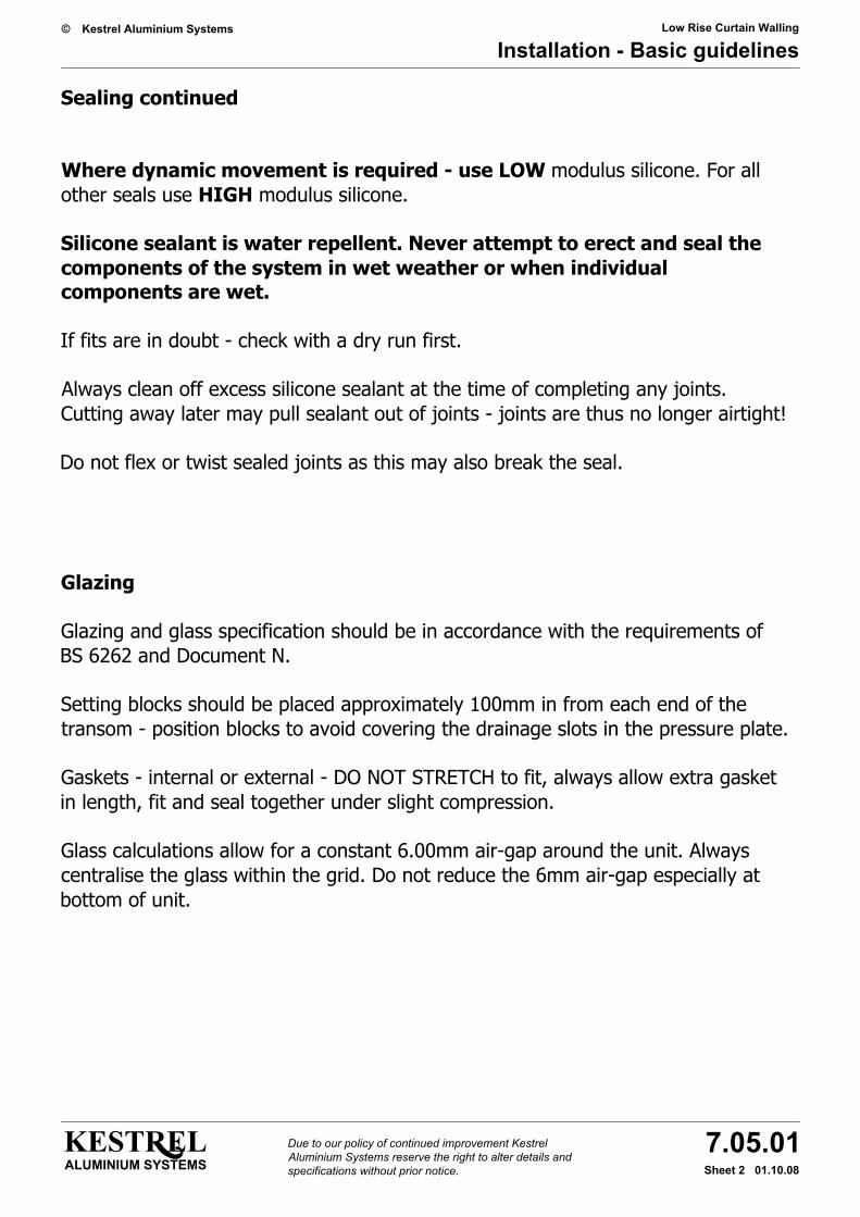
Sealing continued
Where dynamic movement is required - use LOW modulus silicone. For all other seals use HIGH modulus silicone.
Silicone sealant is water repellent. Never attempt to erect and seal the components of the system in wet weather or when individual components are wet.
If fits are in doubt - check with a dry run first.
Always clean off excess silicone sealant at the time of completing any joints. Cutting away later may pull sealant out of joints - joints are thus no longer airtight!
Do not flex or twist sealed joints as this may also break the seal.
Glazing
Glazing and glass specification should be in accordance with the requirements of BS 6262 and Document N.
Setting blocks should be placed approximately 100mm in from each end of the transom - position blocks to avoid covering the drainage slots in the pressure plate.
Gaskets - internal or external - DO NOT STRETCH to fit, always allow extra gasket in length, fit and seal together under slight compression.
Glass calculations allow for a constant 6.00mm air-gap around the unit. Always centralise the glass within the grid. Do not reduce the 6mm air-gap especially at bottom of unit.
Low Rise Curtain Walling
Installation - Transom to mullion
KESTRELALUMINIUM SYSTEMS
7.05.0201.11.14Sheet 1
Kestrel Aluminium Systems©
Due to our policy of continued improvement Kestrel Aluminium Systems reserve the right to alter details and specifications without prior notice.
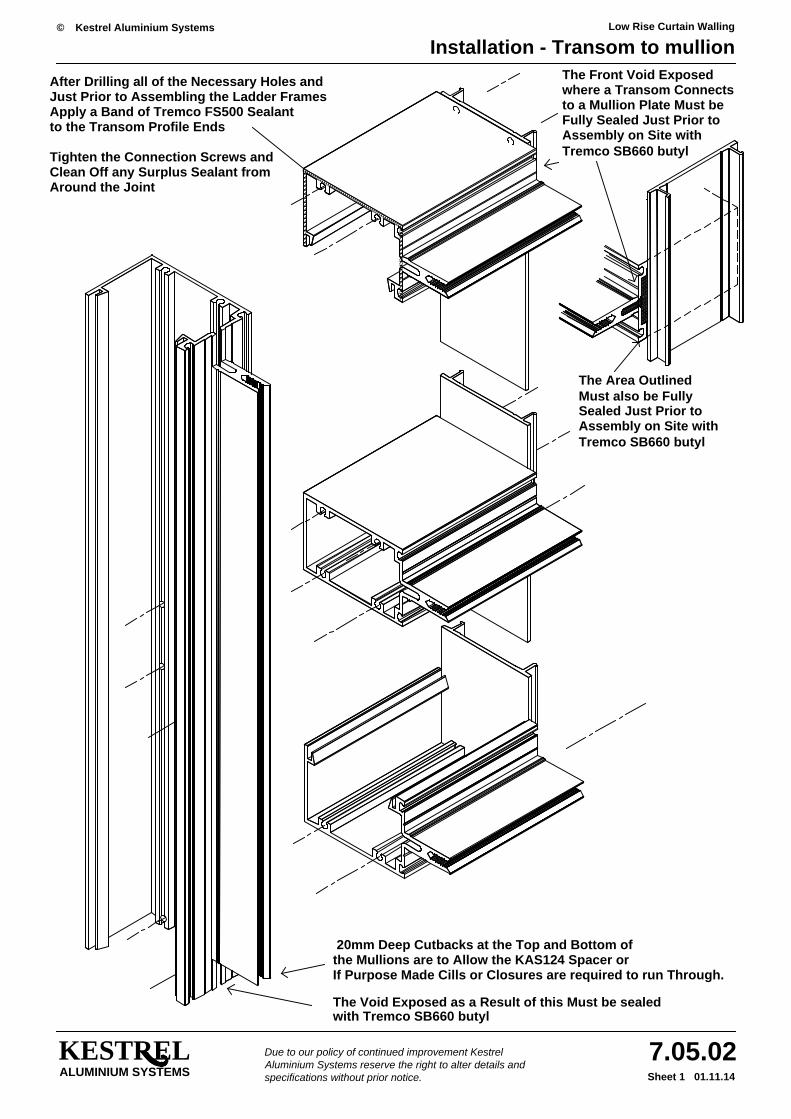
20mm Deep Cutbacks at the Top and Bottom ofthe Mullions are to Allow the KAS124 Spacer orIf Purpose Made Cills or Closures are required to run Through.
The Void Exposed as a Result of this Must be sealedwith Tremco SB660 butyl
xxx
xxxx
xxxx
xxxx
xxx
to the Transom Profile Ends
Just Prior to Assembling the Ladder Frames
Tighten the Connection Screws andClean Off any Surplus Sealant from
Apply a Band of Tremco FS500 Sealant
After Drilling all of the Necessary Holes and
Around the Joint
Fully Sealed Just Prior toAssembly on Site withTremco SB660 butyl
xxxxxxxxxxxxxxxxxxxxxxxxxxxxxxxxxxxxxxxxxxxxxxxxxxxx
Tremco SB660 butylAssembly on Site withSealed Just Prior toMust also be FullyThe Area Outlined
The Front Void Exposed
to a Mullion Plate Must bewhere a Transom Connects
xxx
xxxx
xxxx
xxxx
xxx

Low Rise Curtain Walling
Installation - Installation types - Single storey
KESTRELALUMINIUM SYSTEMS
7.05.0301.10.08Sheet 1
Kestrel Aluminium Systems©
Due to our policy of continued improvement Kestrel Aluminium Systems reserve the right to alter details and specifications without prior notice.
is sufficient to allow the last frame to be manoeuvred and clipped into position. (suggest o/all frame width -20)Always ensure that the amount of lateral space available in-between the last but one frame and the structure
Typical Single Storey Elevation - Scale 1:50
PlatePlatePlate
Full
Stor
ey h
eigh
t
Open Transom
Plate
Open Transom
Plate
Box Transom
Ope
n M
ullio
n
Plat
e
First
Ope
n M
ullio
n
Plat
e
SecondBox Transom
Open Transom
Plate
Ope
n M
ullio
n
Ope
n M
ullio
n
Plat
e
Plat
e
ThirdBox Transom
Open Transom Open Transom Open Transom
Low Rise Curtain Walling
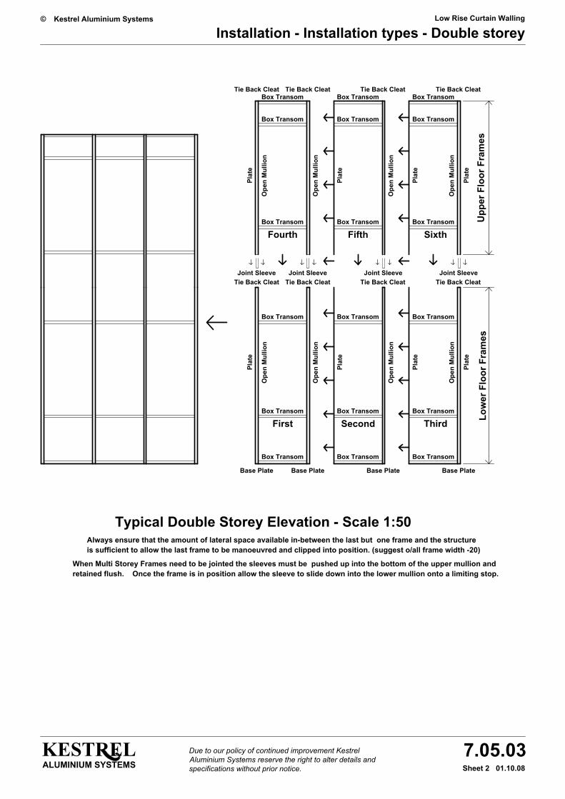
Installation - Installation types - Double storey
KESTRELALUMINIUM SYSTEMS
7.05.0301.10.08Sheet 2
Kestrel Aluminium Systems©
Due to our policy of continued improvement Kestrel Aluminium Systems reserve the right to alter details and specifications without prior notice.
Low
er F
loor
Fra
mes
Always ensure that the amount of lateral space available in-between the last but one frame and the structureis sufficient to allow the last frame to be manoeuvred and clipped into position. (suggest o/all frame width -20)
When Multi Storey Frames need to be jointed the sleeves must be pushed up into the bottom of the upper mullion andretained flush. Once the frame is in position allow the sleeve to slide down into the lower mullion onto a limiting stop.
SecondBox Transom
Box Transom
Typical Double Storey Elevation - Scale 1:50
Box Transom
Base Plate
Box Transom
Base Plate
First ThirdBox Transom
Box Transom
Base PlateBase Plate
Box Transom
Box Transom
FifthBox Transom
Box Transom
Joint Sleeve Joint SleeveTie Back Cleat
Box Transom
Ope
n M
ullio
n
Plat
e
Ope
n M
ullio
n
Plat
e
Tie Back Cleat
FourthBox Transom
Ope
n M
ullio
n
Plat
e
Ope
n M
ullio
n
Plat
e
Tie Back CleatBox Transom
Box Transom
Tie Back Cleat
Upp
er F
loor
Fra
mes
Joint SleeveJoint SleeveTie Back Cleat
Box Transom
Ope
n M
ullio
n
Plat
e
Tie Back Cleat
Ope
n M
ullio
n
Plat
e
Box Transom
Sixth
Ope
n M
ullio
n
Plat
e
Ope
n M
ullio
n
Plat
e
Box Transom
Box Transom
Tie Back CleatTie Back Cleat

Low Rise Curtain Walling
Installation - Zone sealing
KESTRELALUMINIUM SYSTEMS
7.05.0401.11.14Sheet 1
Kestrel Aluminium Systems©
Due to our policy of continued improvement Kestrel Aluminium Systems reserve the right to alter details and specifications without prior notice.
Tremco SB660 Butyl Sealant
Positioned and Sealed Prior to
the Blocks with Sufficient
it is Imperative that Blocks are
Seal the Top Surface Edges of
Butyl Sealant to the Ends of theTransom Gasket Grooves just Prior to Finally positioning the
Apply a Bead of Tremco SB660
'Gaskets Must Not be Cut Short'
Trim the Ends Square usingProprietary Gasket Shears
Avoiding Stretching the Gasket
from the Centre of the ApertureZip the Gasket into the Groove
Measure and Cut the GasketSlightly Oversize and Starting
suit the Glass/Panel ThicknessChose the Correct Gasket to
Any Lineal Butt Joints should be
See drawing 7.05.05 sheet 1
Similarly Bonded and Sealed
Gasket
Gaskets are Bonded and sealedInbetween Transom and Mullion
with Tremco SB660 Butyl Sealant
Ensure that the Butt Joints
Glazing
Mullion and TransomBlocks at the Junction of EveryInsert the KAS867 Zone Sealing
the Curtain Wall Stick FrameAssemble, Line, Level and Fix

Low Rise Curtain Walling
Installation - Zone sealing
KESTRELALUMINIUM SYSTEMS
7.05.0401.11.14Sheet 2
Kestrel Aluminium Systems©
Due to our policy of continued improvement Kestrel Aluminium Systems reserve the right to alter details and specifications without prior notice.
KAS867 Zone Blocks and Seal with
To Ensure that the Curtain WallDrains as Intended Fit the
with Tremco SB660 Butyl Sealant
Prior to Glazing
Chose the Correct Gasket tosuit the Glass/Panel Thickness
Slightly Oversize and StartingMeasure and Cut the Gasket
Zip the Gasket into the Groovefrom the Centre of the Aperture
Avoiding Stretching the Gasket
Proprietary Gasket ShearsTrim the Ends Square using
'Gaskets Must Not be Cut Short'
Apply a Bead of Tremco SB660
Prior to Finally positioning same
Butyl Sealant to the Ends of the
Similarly Bonded and Sealed
See drawing 7.05.05 sheet 1
Ensure that the Butt Joints
with Tremco SB660 Butyl Sealant
Inbetween Transom and MullionGaskets are Bonded and sealed
Mullion Gasket Grooves just
Any Lineal Butt Joints should be
KAS867 Zone Sealing Blocks
Low Rise Curtain Walling
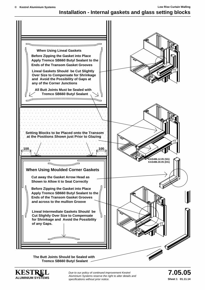
Installation - Internal gaskets and glass setting blocks
KESTRELALUMINIUM SYSTEMS
7.05.0501.11.14Sheet 1
Kestrel Aluminium Systems©
Due to our policy of continued improvement Kestrel Aluminium Systems reserve the right to alter details and specifications without prior notice.
Tremco SB660 Butyl SealantThe Butt Joints Should be Sealed with
Setting Blocks to be Placed onto the Transom
100
and across to the mullion Groove
Cut Slightly Over Size to Compensatefor Shrinkage and Avoid the Possibility
Lineal Intermediate Gaskets Should be
of any Gaps.
Ends of the Transom Gasket Grooves
When Using Moulded Corner Gaskets
Cut away the Gasket Arrow Head as
Apply Tremco SB660 Butyl Sealant to theBefore Zipping the Gasket into Place
Shown to Allow it to Seat Correctly
100
All Butt Joints Must be Sealed with
any of the Corner Junctionsand Avoid the Possibility of Gaps atOver Size to Compensate for ShrinkageLineal Gaskets Should be Cut Slightly
Apply Tremco SB660 Butyl Sealant to theEnds of the Transom Gasket Grooves
Before Zipping the Gasket into Place
When Using Lineal Gaskets
at the Positions Shown just Prior to Glazing
Tremco SB660 Butyl Sealant
KAS486.12.05 (SG)KAS486.30.05 (DG)

Low Rise Curtain Walling
Installation - Glazing and capping
KESTRELALUMINIUM SYSTEMS
7.05.0601.11.14Sheet 1
Kestrel Aluminium Systems©
Due to our policy of continued improvement Kestrel Aluminium Systems reserve the right to alter details and specifications without prior notice.
minimum 50mm long )from offcuts of pressure cap( Stitch plate can be made
of Tremco SB660 to the Outer
Mullion Pressure PlatesPosition and Fix the KAS861
Face of the Zone Sealing Blocks
Still in Position apply a BandWith the Transom Stitch Plates
Clean and Free from Debris
be Seated on Setting Blocksor Insulation Panels ShouldSingle Glass, Double Glass
Ensure that all Rebates areBefore Attempting to Glaze
When Capping Off, Glass can
using Transom Stitch Platesbe held in place Temporarily
Ends of the TransomsPositioned 100mm from the

Low Rise Curtain Walling
Installation - Glazing and capping
KESTRELALUMINIUM SYSTEMS
7.05.0601.11.14Sheet 2
Kestrel Aluminium Systems©
Due to our policy of continued improvement Kestrel Aluminium Systems reserve the right to alter details and specifications without prior notice.
Remove Any Protective TapeClean Down and Ensure thatAll Clip Caps are Secure
Fit Transom Clip Caps
Fit the KAS851 Mullion Clip Cap
the Side of the Mullion Clip Capthe Transom Pressure Plate andFS500 Sealant Inbetween
and Prior to Fitting the TransomCap, Apply a Fillet of Tremco
Mullion Pressure Plates and FixPressure Plates Inbetween the Centralise the KAS862 Transom
Due to our policy of continued improvement Kestrel Aluminium Systems reserve the right to alter details and specifications without prior notice.ALUMINIUM SYSTEMS
KESTREL 7.06.01Scale 1.1
Sheet 1 01.01.10
© Kestrel Aluminium Systems
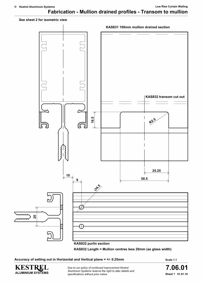
Fabrication - Mullion drained profiles - Transom to mullionLow Rise Curtain Walling
KAS831 100mm mullion drained section
KAS832 purlin section
20
9
KAS832 Length = Mullion centres less 20mm (as glass width)
10
16.5
50.5
25.25
R2.5
∅4.5KAS832 transom cut out
Accuracy of setting out in Horizontal and Vertical plane = +/- 0.25mm
See sheet 2 for isometric view
Due to our policy of continued improvement Kestrel Aluminium Systems reserve the right to alter details and specifications without prior notice.ALUMINIUM SYSTEMS
KESTREL 7.06.01Scale 1.1
Sheet 2 01.01.10
© Kestrel Aluminium Systems
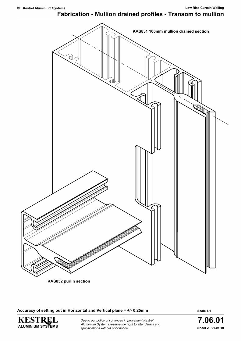
Fabrication - Mullion drained profiles - Transom to mullionLow Rise Curtain Walling
KAS831 100mm mullion drained section
KAS832 purlin section
Accuracy of setting out in Horizontal and Vertical plane = +/- 0.25mm

Due to our policy of continued improvement Kestrel Aluminium Systems reserve the right to alter details and specifications without prior notice.ALUMINIUM SYSTEMS
KESTREL 7.06.02Scale 1.1
Sheet 1 01.02.10
© Kestrel Aluminium Systems
Fabrication - Mullion drained profiles - KAS833Low Rise Curtain Walling
25B
etw
een
200m
m a
nd 2
50m
m c
entr
es
Snap in PVC isolator KAS860black PVC strip - cut length as KAS833 - prior to drilling
Gaskets - 2 x KAS192
Drill and csk for No. 12 screw as shown (6mm Ø)
Drill 25mm in from ends and thenmaximuim 250mm centres.
No12 x 22mm philips csk A2 S/Steel AB self tapping screw
∅6
Due to our policy of continued improvement Kestrel Aluminium Systems reserve the right to alter details and specifications without prior notice.ALUMINIUM SYSTEMS
KESTREL 7.07.01Scale 1.2
Sheet 1 01.11.14
© Kestrel Aluminium Systems
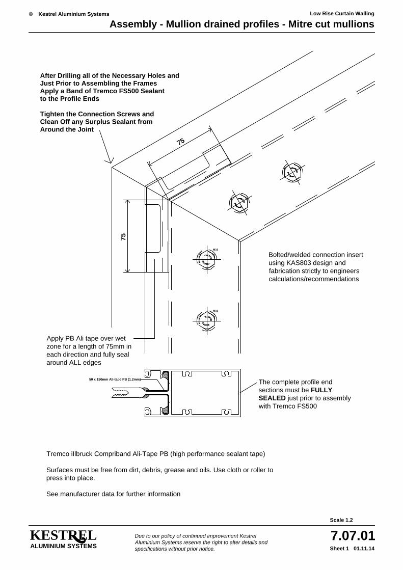
Assembly - Mullion drained profiles - Mitre cut mullionsLow Rise Curtain Walling
Bolted/welded connection insert using KAS803 design and fabrication strictly to engineers calculations/recommendations
M10
M10
50 x 150mm Ali-tape PB (1.2mm)
75
75
After Drilling all of the Necessary Holes and
Apply a Band of Tremco FS500 SealantJust Prior to Assembling the Frames
Clean Off any Surplus Sealant fromTighten the Connection Screws and
to the Profile Ends
Around the Joint
The complete profile end sections must be FULLY SEALED just prior to assembly with Tremco FS500
Apply PB Ali tape over wet zone for a length of 75mm in each direction and fully seal around ALL edges
Tremco iIlbruck Compriband Ali-Tape PB (high performance sealant tape)
Surfaces must be free from dirt, debris, grease and oils. Use cloth or roller to press into place.
See manufacturer data for further information
Due to our policy of continued improvement Kestrel Aluminium Systems reserve the right to alter details and specifications without prior notice.ALUMINIUM SYSTEMS
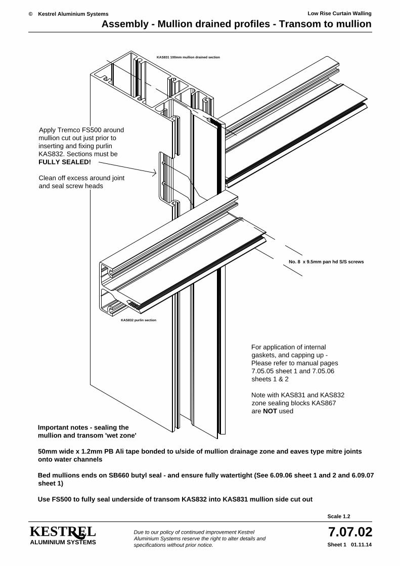
KESTREL 7.07.02Scale 1.2
Sheet 1 01.11.14
© Kestrel Aluminium Systems
Assembly - Mullion drained profiles - Transom to mullionLow Rise Curtain Walling
KAS832 purlin section
KAS831 100mm mullion drained section
No. 8 x 9.5mm pan hd S/S screws
Important notes - sealing the mullion and transom 'wet zone'
50mm wide x 1.2mm PB Ali tape bonded to u/side of mullion drainage zone and eaves type mitre jointsonto water channels
Bed mullions ends on SB660 butyl seal - and ensure fully watertight (See 6.09.06 sheet 1 and 2 and 6.09.07 sheet 1)
Use FS500 to fully seal underside of transom KAS832 into KAS831 mullion side cut out
Apply Tremco FS500 around mullion cut out just prior to inserting and fixing purlin KAS832. Sections must be FULLY SEALED!
Clean off excess around joint and seal screw heads
For application of internal gaskets, and capping up - Please refer to manual pages 7.05.05 sheet 1 and 7.05.06 sheets 1 & 2
Note with KAS831 and KAS832 zone sealing blocks KAS867 are NOT used
Recommended


![[BS en 13947-2006] -- Thermal Performance of Curtain Walling. Calculation of Thermal Transmittance](https://img.dokumen.tips/doc/110x75/5695cef11a28ab9b028be4b2/bs-en-13947-2006-thermal-performance-of-curtain-walling-calculation-of.jpg)