. \b
-ABSTRACT
PRACTICAL APPLICATIONS OF STRESS-WAVE THEORY IN PILING DESIGN
By Charles H. Samson, Jr.,l M. ASCE, Farland C. Bundy,2 M. ASCE
and Teddy J. Hirsch,3 M. ASCE
,~.31(~
Extensive efforts have been devoted in recent research studies to
obtain a suitable means of applying wave theory to pile-driving problems
for use by practicing Civil Engineers. Through use of a digital computer
program devised to account for the significant factors, design engineers
of the Texas Highway Department Bridge Division, working closely with
research engineers of the Texas Transportation Institute at Texas A&M
University, have applied this procedure in their pile-driving problems.
Of special concern were long prestressed concrete piles driven in various
causeway projects along the Texas Gulf Coast. In this paper are discussed
various a~plications ofsfress-wave ttieoryc-o·p-rn·C"rtc-a'l· p-i:Hng p~oblems •
\ . -· f
I l ..... . ! ' • ;. ., i •
•. , ,"'7 '..J
;':~·
1 Professor __ of_,,S.tru_ct.uraLEn.gj.~E=.ring_a.R,<!.. ~tructural Meehan cs, Depts. of Civil and Aerospace Engineering, and Head of Structural Research Dept., Texas Transportation Institute, Texas A&M University, College Station, Texas.
2 Supervising Design Engineer, Bridge Division, Texas Highway Dept., Austin, Texas ..
3 Assoc. Professor of Structural Engineering and Structural Mechanics, De.pt. of Civil Engineering, and Assoc. Research Engineer, Texas Transportation Institute, Texas A&M University, College Station, Texas.

PRACTICAL APPLICATIONS OF STRESS-WAVE THEORY IN PILING DESIGN
By Charles H. Samsop~ Jr.,l M. ASCE, Farland C. Bundy,2 M. ASCE
and Teddy J. Hirsch,3 M. ASCE
Background
Since 1961 an intensive research study has been underway at Texas A&M
University on dynamic behavior of piling during driving. The work has
been sponsored by the Bridge Division of the Texas Highway Department
during this time, and for the past year cosponsored by the Bureau of
Public Roads. The research was initiated as a result of difficulties
encountered in driving prestressed concrete piling during the construe-
tion of the Lavaca Bay Causeway near Port Lavaca, Texas. Several
piles 70 to 110 feet long developed transverse cracks and failed com
pletely during driving.
In an effort to determine causes of the cracking and possible
remedial action, a project was begun with the objective of developing a
computer program based on the work of E. A. Smith (1). ~·: Mr. Smith, who
was fonnerly Chief Mechanical Engineer for Raymond International, Inc.,
but now retired, worked extensively over a period of several years to
1 Professor of Structural Engineering and Structural Mechanics, Depts. of Civil and Aerospace Engineering, and Head of Structural Research Dept., Texas Transportation Institute, Texas A&M University, College Station, Texas.
2 Supervising Design Engineer, Bridge Division, Texas Highway Dept., Austin, Texas.
3 Assoc, Professor of Structural Engineering and Structural Mechanics, Dept. of Civil Engineering, and Assoc. Research Engineer, Texas Transportation Institute, Texas A&M University, College Station, Texas.
~·: Numbers in parentheses refer to list of References at the end of the article.

adapt one-dimensional wave theory to the dynamic behavior of piling under
the impact of a pile-driver ram,
2
In 1961 a computer procedure was developed at the Texas Transportation
Institute (2) at Texas A&M University as the first phase of the research ..
The program was designed for the IBM 709 Digital Computer at the A&M Data
Processing Center. Mr. Smith served as a special consultant on this work,
Since 1961, the research has continued in several directions, Several
piles have been instrumented and field tested for stress, strain, and
displacement data. This work has been described in two reports published
by the Texas Transportation Institute (3, 4). A general discussion of
dynamic behavior of piling as predicted by wave theory, based on this
research, has been published by Institute research engineers (5). A study
is also under way in which the computer procedure is used to determine the
influence of different variables on the behavior of piles during driving.
An interim report (6) has been prepared on the portion of the study thus
far completed.
Stress-wave Theory
The stress-wave theory used in this research is based on classical
one-dimensional wave theory, details of which may be found in References
(7) and (8).
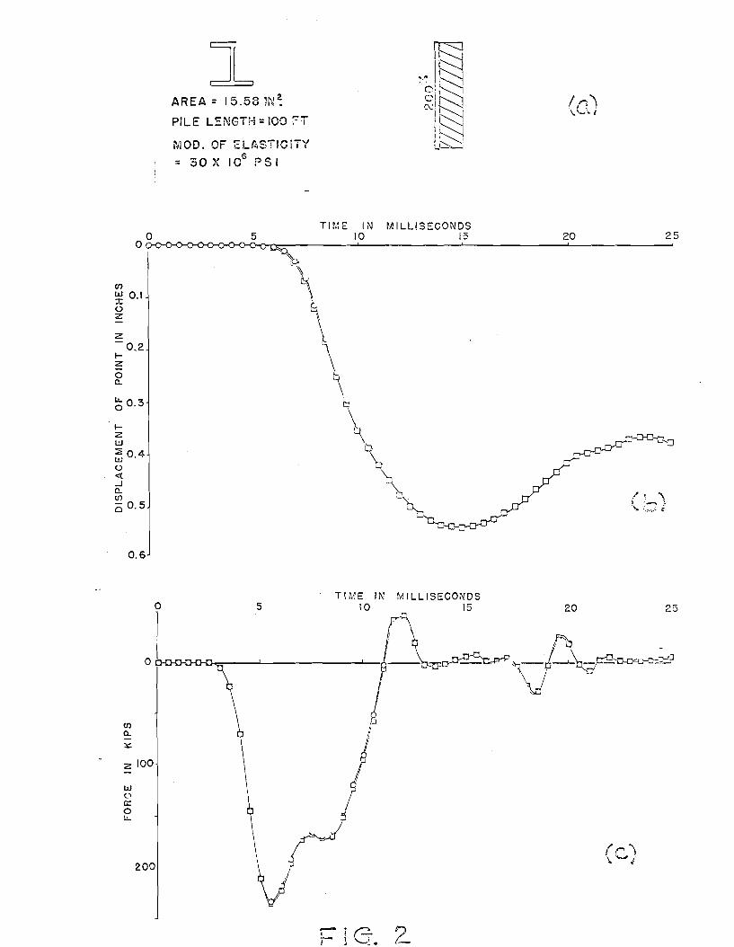
Figure la illustrates a typical pile-driving situation. Figure lb
shows the idealized representation used by Smith in developing his pro
cedure. The pile is pictured as series of discrete weights and springs,
properties of which are determined from the properties of the actual pile.
Load-deformation characteristics of the pile material, the soil, the cap
block, and the cushion block must be predetermined. The weight and impact
velocity of the ram must also be predetermined.

3
In the application of this method a relatively small increment of time
is selected. The analysis becomes a step-by-step operation initiated by
the impact velocity of the ram, assumed to remain constant during the first
interval. In sequence, then, displacements, internal forces, and soil
reactions may be determined for all segments. With this information, it is
possible to calculate new velocities for all segments for use in the next
time interval. This sequence of computations may be continued until the
desired information is obtained. Information that would prove of interest
to a design engineer might be, for example~
1. Permanent set per blow.
2. Maximum compressive stress and maximum tensile stress that might occur during one blow in any segment.
3. Variation of stress with time for each segment.
4. Variation of displacement with time for each segment,
Such data may be readily extracted from the computer solution.
Example
As an illustration of theory, the pile of Figure 2a is shown, along
with the idealization used in the computer. The pile properties are taken
from Reference (1). The total ultimate soil resistence is arbitrarily
taken to be 200 kips uniformily distributed along the side. The resistance
for this particular case is considered to be entirely side friction.
Other pertinent information is given as follows:>'(
Hammer energy= 12,000 ft lb
Impact velocity of ram= 12.4 ft per sec
Weight of pile cap= 700 lb
Capblock stiffness= 2xl06 lb per in.
,•, The reader is referred to References (1), (2), and (5) for more detailed discussion of these factors.·

Coefficient of restitution of capblock = 0.50
Soil quake (maximum elastic deformation)= 0.1 in.
Soil damping coefficient= 0.05 sec per ft
4
Figure 2b illustrates a typical displacement versus time plot obtained
from the computer solution. The particular curve shown is for the point
of the pile. Figure 2c shows a plot of force versus time for the mid-point
of the pile. The set per blow was determined to be 0.39 in.
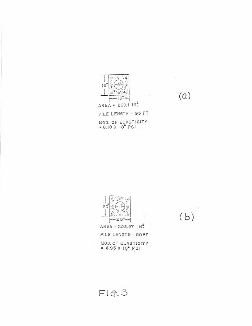
Practical Application
Bridge Division engineers of the Texas Highway Department have put
stress-wave theory to work in solving practical field problems. In the
construction of both the Lavaca Bay Causeway and the Nueces Bay Causeway
on the Texas Gulf Coast, long prestressed concrete piles (70 to 110 feet)
were driven. Cross sections of piles used on the projects are given in
Figure 3. A general view of the partially completed Nueces Bay job is
shown in Figure 4. The rig that appears in the foreground is taking soil
borings. Piles were driven by a diesel hammer having the following
characteristics:
Rated Hammer energy= 39,800 ft lb
Weight of ram= 4,850 lb
Figure 5 shows a pile positioned for driving at the Nueces Bay site.
On the Lavaca Bay project, cushioning was provided by a circular
one-inch plywood capblock and a three-inch thick oak cushion block. The
cushioning on the Nueces Bay project consisted of the same type capblock
as used in the Lavaca Bay work and a six-inch oak cushion block.
On both projects there occurred some instances of transverse cracking
in the piles of the sort shown in the close-up view of Figure 6. Here the

crack has been filled with an epoxy adhesive in an effort to pennit
redriving of the pile. Obvious questions were: What was the cause?
What corrective measures could be taken?
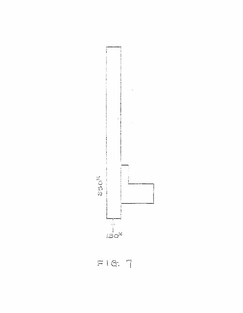
As a means of shedding more light on the problem, a specific pile
installation at the Lavaca Bay site was selected for theoretical inves
tigation. Based on soil data acquired through soil borings, the soil
resistance for a 90-foot pile at a penetration of 30 feet was estimated
to be that shown in Figure 7.
In order to observe the effect of different hammer energies and
different ram velocities, three different sets of hammer characteristics,
representative of different pile drivers in use, were selected for study.
These were as follows:
Hammer A:
Diesel hammer
Ram weight= 4,850 lb
Rated energy per blow= 39,800 ft lb
Maximum explosive pressure on pile= 158,700 lb
Hammer B:
Single-acting steam hammer
Ram weight= 9,300 lb
Rated energy per blow= ~J,225 ft lb
Hammer C:
Single-acting steam haffimer
Ram weight= 14,000 lb
Rated energy per blow = 37,500 f:: lb
5
Figure 8 provides curves of maximum tensile stress versus impact
velocity. The maximum tensile stress is the maximum developed in the
pile considering all time intervals and all pile segments. For a given
hammer, different impact velocities correspond to different hammer
efficiencies.
In the plot of Figure 8, two curves are given for Ram A: one
accounting for the internal explosive pressure, one allowing for no
internal pressure. Since there is some question ·among engineers as to
the degree of influence of explosive. pressure, the two curves bound the
range of effectiveness.
Also in Figure 8, for each ram two cushion blocks were considered.
The dashed curves represent results based on cushioning provided by a
6
new block. Because continued use of a cushion block continues to per
manently compress it, leading to a considerably increased stiffness,
comparision curves are shown for cushioning having a stiffness arbitrarily
increased ten times over that of an unused block. That a great amount of
compression occurs is evidenced by Figure 9, in which the capblock and
cushion block used at Nueces Bay are shown before and after driving. The
charred appearance of the capblock and the "squashed" appearance of the
cushion block in Figure 9b attest to the amount of compression that has
taken place.
No attempt will be to generalize on the basis of the limited results
shown. It should be noted that the soil resistance in Figure 7 is ex
tremely light and indicative of resistance encountered during the initial
stage of driving. In Figure 8, all tensile stresses plotted exceed the
800-psi prestress in the pile. Of course, adding the tensile strength of

the concrete to the prestress would provide perhaps 1,200 or 1,300-psi
total ultimate strength.
The results of Figure 8 support certain conclusions, at least for
the circumstances considered:
1. In conditions of low soil resistance, very high tensile stresses may b2 developed.
2. A softer cushion block will in general lead to lower maximum tensile stress.
3. The influence of diesel hammer explosive pressure on the maximum tensile stress does not appear significant.
4. For a given ram, the development of high tensile stress is greatly influenced by the impact velocity.
One immediate step that was taken by Bridge Division engineers was
7
to insist that new cushion blocks be installed at least with each new pile
being driven. On the Nueces Bay project, this step alone appeared largely
to eliminate the cracking problem. A further practice that was followed
in some cases of very light drivic.g was the pre-drilling of a slightly
undersized shaft to a depth offering firmer bearing. Since the pile couLd
be positioned at this depth without impact driving, the period of greatest
danger of tensile cracking was avoided.
Other remedial steps that suggest themselves on the basis of Figure 8
are the use of a thicker cushion block and the decrease of impact velocity
by decreasing the stroke of the pile-driver ram during periods of low soil
resistance.
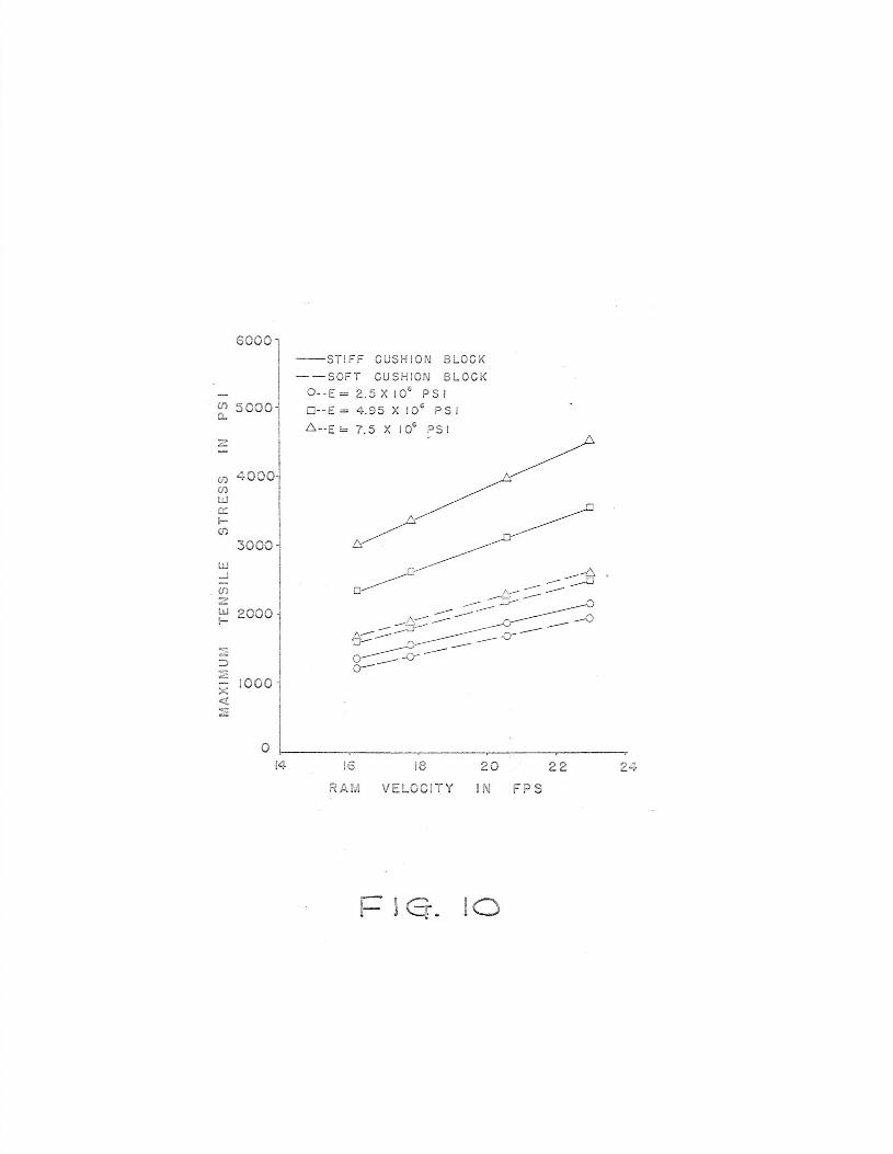
fc. is some interest to note the influence of modulus of elasticity on
the magnitude of maximum tensile stress developed. Figure 10 is a plot of
maximum tensile stress versus ram impact velocity for the diesel hammer.
It is noted that a significant increase in tensile stress occurs with an
increase in modulus of elasticity. These results suggest the interesting

8
possibilities of use of lightweight aggregate concrete, with its character
istic lower modulus of elasticity, as a material for prestressed concrete
piles.
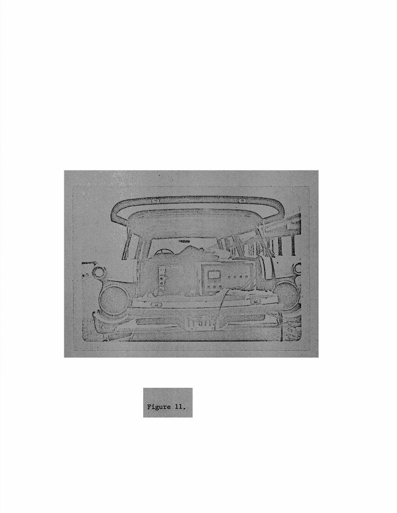
Field Tests
Field tests performed during the research at Texas A&M are described
in detail in References (3), (4), and (7). These tests have provided data
on a recording oscillograph (see Figure 11) for stress variation with time
at different points along the pile and displacement variation with time
at the head of the pile. Electric resistance strain gages embedded in the
pile measured strains. A linear voltage displacement, shown in a close-up
view in Figure 12, transducer measured the travel at the head of the pile.
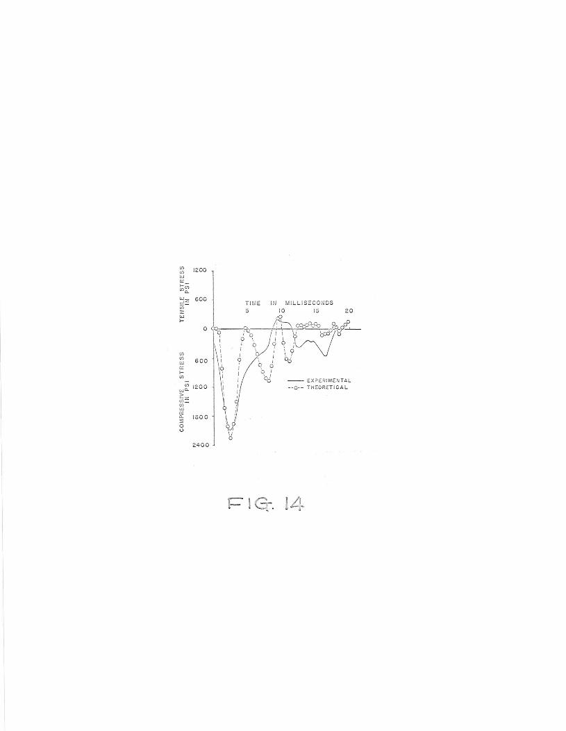
Figure 13 shows one set of oscillographic data taken from the recorder.
Experimental data acquired in this way are being correlated with corre-
sponding theoretical solutions obtained by the computer stress-wave program.
Figure 14 shows one such correlation, taken from Reference (5). Consider-
ing the uncertainty associated w~th soil factors, the correlation is thought
to be encouraging. Further research related to dynamic soil behavior is
expected to improve the correlation.
Future Applications of Stress-wave Theory
The objective throughout the Texas A&J.~ research has been to develop
an effective and reliable method for use by practicing engineers concerned
with designing piling and determining driving conditions. It is expected
that practical use may be achieved in several ways:
1. Where a large computer is available and where soil information is known, specific problems can be solved, as illustrated by Figure 8.
2. Where a computer is not locally available, a central service organization may be used. Texas A&M, for example, has such facilities.
9
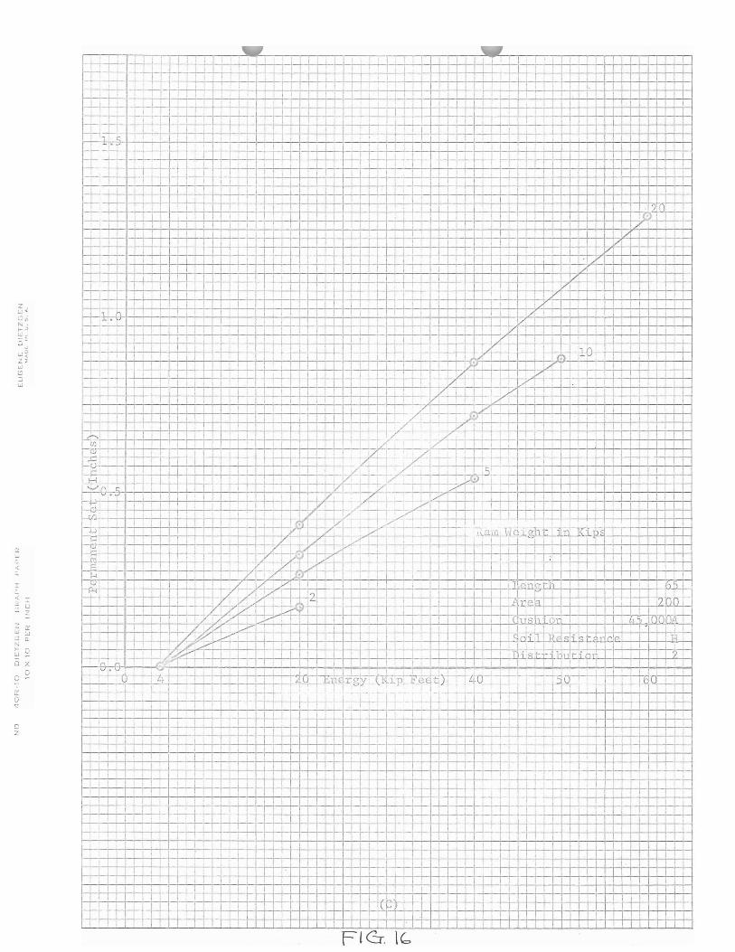
3. Parameter studies currently in progress should lead to much generalized information that can be of direct benefit to the practicing engineer. For example, Figure 15 has been extracted from Reference (6), in which a whole family of such plots has been developed. Plots of maximum stress versus impact energy for the conditions indicated are given. A separate curve is provided for each ram weight. Figure 16, also taken from Reference (6), provides curves of permanent set versus impact energy.
4. Extensive comparison of stress-wave solutions with those from simplified formulas should define more clearly the limitations and the ranges of applicability of the formulas.
Future Research at Texas A&J.v1
Future research planned includes continued field tests to provide
correlation information; additional generalized paramenter studies; iso
lated experimental studies of piling and cushioning material, pile-drivers,
and soil factors; and continued refinement of the computer program. The
research engineers hope that their efforts will lead to a reliable means
of theoretically determining driving stresses, displacements, and ultimate
bearing capacity by means of a digital-computer analysis.
References
(1) Smith, E. A. L., "Pile-driving Analysis by the Wave Equation," Transactions, ASCE, Vol. 127, 1962, Part I, p. 1145.
(2) Samson, Charles H., Jr., "Pile-driving Analysis by the Wave Equation (Computer Procedure), Report RP 25, Texas Transportation Institute, Texas A&M University, Hay, 1962.
(3) Hirsch, Teddy J., "Stresses in Long Prestressed Concrete Piles During Driving," Report RP 27, Texas Transportation Institute, Texas A&l.~ University, September, 1962.
(4) Hirsch, Teddy J., "Field Tests of Prestressed Concrete Piles During Driving," Report RP 27-2, Texas Transportation Institute, Texas A&M University, August, 1963.
(5) Samson, Charles H., Jr., Hirsch, Teddy J., and Lowery, Lee L., Jr., "Computer Study of Dynamic Behavior of Piling," Journal of the Structural Division, ASCE, Vol. 89, No. ST5, August, 1963.
(6) Hirsch, Teddy J., "Computer Study of Variables Which Affect the Behavior of Concrete Piles During Driving," Report RP 27-3, Texas Transportation Institute, Texas A/01 University, August, 1963.
10
(7) Hirsch, Teddy J., Samson, Charles H., Jr.~ and Lowery, Lee L., Jr., 11 Driving Stresses in Pres tressed Concrete Piles," presented at National Meeting ASCE, San Francisco, California; October 7, 1963. _

{A) ACTUAL ?ILE
~ i I !
I
I VJc 10) I e'_ ,.,1
'' c10)~ r r, <10> r\ ':i W,·~
VJ cm j " , ._,1( J I) ,,.. 2 '7f\
f\ (11) - v:.t= i
SIDE FRllCTIONAL RESISTANCE
~ . , I t\, < 12> POINT
r,.,:Cl 2)f-<-- RESISTANCE C\ ,;~
(8) I D E A LIZ ED PI l E
0
en ~ 0.1 (.)
z
z 0.2
I-z 0 0..
~0.3
I-z w ::e:04 w . (.)
<t ...J 0.. (/)
c 0.5
0.6
Cl)
a.. ~
0
z 100
0
l
200
1 AREA= 15.58 l~J:
PILE LENGTH= 100 ?'T
MOD. OF ELASTICITY
=30XIOGPS1
5
\ ~.
TIME IN 10
18:3 ,.ftl~2jl " ii-~
8.1~1N·. c,;1 i ! ; I It 1·,~ i (, -.............~. c.;--
MILLISECONDS !5
\ \
b
\ \ cJ
\~ ~\ . ., n
TIME IN MILLISECONDS 5 10 15
rlG, ii " ~ •
2.
to-' \. • I
20 25
20 25
PILE LE GTH = 95 FT
MOD. OF E~AS ICITY = . 18 )( 10 P SI . ·
T . ~--i:/i:: ·o· .. c-. . J,
201 _i{@-i-. _i _.- ·. ·_,:6\~j; t-- 2 "--i
AREA = 302 .97 I ~
PI LE LE G H = 90 FT
MOD. OF EL A STICITY = 4 .95 )( IOa PS I
(Q)
( b)

I
\ it '
I . j ,., .. __ ............. _ __.,__. ______ ------· ___ ___... __ ____
Figure 4.
. .. J ·1
.)
} . I
(
'
I I \ ' ' I
I . \ .J
l ) )
) . -'

~ 1 cr. 5

/-----------/~/ ------------0111,/ ? / /
/i /j I
. i I
) I
' I I I
i v )-_ ________________________ ~I//
G
- ~
I~
' '
1

70001
6000
5000
(J) 4000
~ I ~ 30001'
w
: zoooj
?ILE llI, CASE I
-- STIFF CUSHJO~J JLOCK
--- SOFT CUSHION SLOCK
0 RAM A WITH EXPLOSlVE PRE;SSURE
D R~M A WITHCUT EXPLOSIVE PRESSURE
L:::. RAM a 0 RAM C
~ II ~ X /\-~ p =i1000J~~-
1cr
0 '---~---~----~---~------~----JO 12 14 16 18 20 22 24
RAIA VELOCITY IN FPS
G-. . 6

Figu:c2 Seo
Figure 9bo
6000 --ST I FF CUS H IO N B LOCK
-- SOFT CUSH ION B LOCK
0 -- E = 2.5 X 10° PS I
Cll 5000 0 - -E = 4 .95 X 10 6 PS I a..
z
(/) 4 000 (/)
w a:: l-(.f)
3000 w _J
CJ)
:z w 2000 l-
~ ::)
e 1000
X <! ~
0 14
6--E == 7.5 X 10⁶ PS I
16
RA 18 20 22
VELOC IT Y IN F P S
r= J 0 . 10
24

.Fl Gr.·

I I
'le tic 13-1 St;:ale l " = 375 X 10- 6 in/ i n or , II := JC 68 I Os O i O .L
l"
Te, .s :Lo·, l .
Ca ge 1 I I C01 ilp , ~ ~\r v - "" v-
I ( Iei ~s i o .. Ga £E'. 2 j (\ - - = ~ -t
:;..11:2 .. __
i\V \ h/ - -Cor h.p O
\ I Ca r
~ Te, nsio .
ge ./c..,,,- .,_.c:,, .. -i-== j t 1 !/ Cor hp' .~ \
J /1 0( Sec ond TimE Lil es I i---
l '
\
f=" l G-. I 3
(f) 1200 Cf) 1 w a:: f- -
"'"' c..
~:= 600 TI ME IN MIL L IS ECO DS
(f) 5 10 15 2 0 = w
f-
0 R:i I 0
0 ' f . 0 I
' Cf) I Cf)
600 \ I w 0 0 a:: I f- 0 I Cf) ~ -- E XPE RI MEN TAL
Cf) 12 00 - -0·- T HEORE T I CA L we.. > - z "' -Cf)
w 0:: c.. 1800 ::; 0 0
24 00
l= I 4

C C
tr w a. <( a.
I a. < tr l:l
z w l:l N I-l,J
0
0 -;-a: 0 7 (')
ci z
I u z
tr w 0.
0 -X 0
Flcr lS
'3 ""< zr
< -.. u - z
- :r iJ.. ~ lJ a.
' ~ ~ 0 X
0 C
0 z
... --. t L -·-. '- -1-h-W-!-~ I ; : I +-,+--: I I : I ~,---;'-"'--l----'--'-1, -1-,, ..;1 _ _;__1~-~1'-, -,.-;-,:'-!-.LI 1_,_1:f-,:-,
-L- -, - ~'-:1 • I : I i : : ' : I I I ' : I ' I ' : : : ! I I I I ' :~~ I : I
r- • - I J ; ! 1 , , J 1 1 1 1 1 i 1 1 1 -t-r- t I I J l , , I I 1 ·111 _I_,-+ +- ~+~ ,-,~'=F=F' ' I I I I IL ' >-~ I ! ' I I I I I ' I I ' I I Ill I II : II
-+ I I : I' I I I JI ~I_·, '. '11 I I I I I I I
~ -r-r ', T-i-f--;-r:: ----+-.. . - I
1 1 ~. r , 1 1 , , r , , , , , 1 , 1 , 1 1 1 ,-r·-..,-1_ 11,.1. H-,1~r-H~,
1
1, I ,1 11111 I ,11 1·:;-·C" ~-,--1-l: I I I I • I I I : ~~I I I -;--r, I I I i I I I I I ! I I I -·- I~ l'I 1 1 11.1 l,I ',I I I ii I I •II II I I 11,
1-, _,___ '.-. ,-~~-:f~i :--t~,---.--i-'I 1 . I 1,, ' 1 1-L -- - - --· I I I - ' ' -'----' i I ' I ' I I ' I I I I I I I ! I _L +..- ~-,_;_; I ' : I I ' I I I I : I I ' I I I ; I I I I I I I I I I I I I I
' ,, 11: ',11,:1 I 1111 '11• I I I 11 1 1 ' I 1:11 'I I : 1 1
-, -r-'- ri--1--; i I I I I I ! I i ! I I I I ! I I : 1 I I I I I I I I I I I I i I I I -1- I,, I l,'ft+fi I I I! 1 If J I \ ill I 1111 ! ,, i' [ II ~L:::r:=:.:::=, 1-! : , ~·- 1 1 , 1 , 1 ;T 1 , , , , 1 1 , 1 1 , , , 1 1 1 1 1 1 , 1 , ; r
! ' i I ' -r· ~I I I I I I I I I I I I I I I I I I I I I J L I I I I I I I I ?~l"\...---i-T ,--, i I I . 1 j \ , 1 -,-i---1 : ' , , 1 ; I , 1 ; I , 1 , l_!___L_ , I ' I I I --r( ·t1
. ,.:::. --,, I I I • I I: I I I I I I I I I I' I I I I I I Iii I I I I I / I I
-!.--l__l__l__'. I, 11! 'I I I ,: I,, I 11111 11 1111 I I / , I t-:--=r== _ I I I I l I I I I I I ~ I I I 1 I I I I t I I I t I I I/ i l-J_-,---,- I I I I I I I I : I I I I I I I ' ' I : I ! : I I i I ! I I I I Vi I I I I
1 , I I I I I I , I, 1 1 I I I I I I I 1' I I I I I 1 · 1 / I I I' I i----t-' I I I I I I I I I I I I I I I I I I I I I I I I I I 1/f I I I I I
I I I I I I I I I I I I I I I , 1 I I I I I I l I I 1/i I I I I I I I -,-·, I I I: I! I I 'I I JI I I I I 1 1 1 I'' I, I I Ii I I: Y I I I 1 1' I I ~-1-' I I ' : I I I I I ! I I I I I I I I I I I I I I I I ! I I --.-,-/ ' : I i I I
I I I I I I I I: I I I I I I I I I I : I I I I I: / ' I I I I I I 1·:;--r-,..... 1 1 1 1 1 1: 1 1 1 t 1 • 1 1 , 1 . / t 1 , , 1
_, _ ... • v 1 1 , 1 , , 1 , , , , , 1 , 1 1 . 1-v , 1 1 ,___ -- , 1 ; 1 , 1 1 1 1 1 , i 1 , (_..;.J_L...~~ / , I 1 1 1
I I I I I I
'---"---- I : : I I I i I ! I I I' I I I ' I y- I I I I I --+-+-4---'-'--+-i _,_-+-__ __,, >---:.+"-T--1+ : I I ' I: : I
1: I;; I I ! 1 1--c-i+.r-/,{, I
1 1 1 h."1-Li-lD-l---,,--+--.l...,1-+--'!--'-'-'-11- !----al
I : I : : ' : I : I : : I : ; : ' I I : I / f--/-· ,,r<'• : : i ; ' I I : : I I I I I I I ' I I I I I ' ,-~ / - - ,--i--' I I I I I I I I I I I
I I I I I I I I I I I I I 1 /-· - I' I I I I I I I I I I ' I I - '--· . - - , . -~.- , I I I I I I
: : i : , ; : I: I; ; : ! , +--' ~-- /0 : ;' 1 ----~,::: I ~ : :, · ! : : !
, 1
1 : : : 1 1
~ 1
f : , , , --r-..;.--r=;:A~- -=..~/ ~~~;..=.~ , : 1 1 , : : 1 1 1 , ,
I I I !II I I ii '·~+ ,.L- •-/.~' ' I I: ,'1'!1 1, 1111 1 I I I I I I I I I il' I / j---,-,-.l._J I I l i I ! I I I I I 1 , , 1 , 1 , , , · , ·---=--=:: -,, = 1;.. 1-,-:_;_q __ ~1 J : 1 1 1 1 1 1 1 1 ,
: ' I I : I I I: i :, __J~' /-=:-L~-~~-~ ~' ,~,: ' -:--..i;il11.Ji.e..:..g11i-, i:n 'R'-i ,:,,t -- -I -;--1l--"1,- '--'1i_;_1-1
I I I ' ! I I I ,--,---,- -- /~,) ' ~ I I : I : I : : : I I I I - ·----,--l ~ -- • --i----- --'---'- I I : I , , I
1,1,,,11,,1 X'"" ', ,, ,,,1,,.11 ,.1 11111 1 , 1 , _1 ,~- -/ - - . 7,__CJ - ,___,_ 1 , 1 , , 1 , , , ! • 1 1 , , 1 1
:','.:; ~~]~-:: ~ :,;:: 1
: •: 1
1
1mncrr~ I:: I ' :At;; 1
1 I I I I ~2.__.. ~~ ~, I ' I I l I
I l_,,.cr-,--',-+i-1-~l,_.-;--1-~l-.-t--,---+--,,,~',,+I .--I , 1 , , ~ 1 ___ ~ L.!-- +-p=p' , ,
1 1 , 1 1 , ! 1 , , t r.e:::i . 1 1 :nH1
1 1 1 ; 1 , __ -,----,---+---,- I ,-+-,_
1 ___ ---1 ____ _,i 1 , 1 1 I , 1 , , I I ::
111',!~_,_1__
1 I
, , 1 1 ~: J 1
,1
, 1
'. , , 1
• 1,
1, , 1 1 u1,st1ir,ct , 1 u., 11111
I I I I I I ·- I I I I I I ' ' _J_ ' I .'....L!... I I I I I I
I 1 1 , , ~-~-, _ , I . ,' 1
: , 111~
11_1-l- , • , , 1 , c o{Clld.s:i.s.t.ar c:...,: : 1'r ,
I I ! r" -1.J._ I : I I ! I i l +- - I I I ·= r----'_.., --+-- -',-'<l-'-, -I
1-----'--'-- - i I ' 11 , , , • ~ 1 , I , ,n;~.i-~R buti.ori 11 1 ?I 'r. r, I • l'1i ' I I I I -1..'. I I I I I I I ~ I I I I I I v . v - ' ' I I I I 'I di ' I I L I I I I i
-,- __ o-q.-1-;-.- I I 1-+--r------.z...9-'-E11 rgy(Ki.'n'-Feqt) - 40 -~--1-i-+- , "io-. I Bl) I 1 ' I 1 I · 1 I , I ' - I I I , -1 I , 1 I I I n=:---+--:--. ,, ll[i .._,. ... , ,t, I I Iii I I I I I ---;-r--;-- ' i I I ,·-r- -t- i-, -r-~ ' f t-- r -· - ~ I I I I I I I ' ' I I
I I I I I ' I I I I I ' I ' I I I : I I ' I I I ! I I I I
: I ~ I ; ' : ~: : ++--h I : I -+i_L!jj~---,-~--1 1111 I I : ' I~ 1: I : I I I I I I , • , , , , , I · I I I , I I , · .: .. -1~--:---~--I · , , ,~-~ -----: ! '1 'l, , ·-I I I I I ' I I I I ' i I I I I I i ' I i - ,__; i - +- I I -- +-+ I i .
I
1
: ':: : : : : : ',r+ I:: I '''' 'II: I: IT ':I: :~-i:y _ __;._+-~-#·' ~·++LU~t-1 ! I I I I I I I I I I I ! I , I I I • i I I I ~ __ L_ _ +-i-...+--,------,1---.-..--;... , , 1 , 1 1 ! , , i 1 1 1 1 , , -r-r , 1 1 , , , , , , 1 , . , . 1 , , .L..
' I r r ' 1 1 I 1 ' i I 1 1 , ir-1 1 I , I i 1 , 'I ·----,-i-......,- \ , 1 I , 1 , l I I I I I I I i I I _J • I I I I I I I I I , ...L ' 1 I i , I I I I I I 1
1 1 , , 1 , 1 1 , 1 , ..(__l______j ~ , , ' 1 1 1 1 1 , :_J___'.___J - r·- ,-:--1- 1r , , , 1 1 , , , , 1 1 1 , . , 1 , 1 1 1-~ 1 1 1 1 1 : :·T -rr-, 1 1 1 , I , 1 1 ,
I ' I ' I : l I u ' I ' I I I I I I L I I I i I I ' I ""TiT: I I if-+' l I I I r,·-- 1 I 1 , ,.-~-r;----i- 1--+---r1 I I r I I I I! -r I I , I I I I I 1 , , r I I ,
i ; I I ' i I ' I I -h I I I I I J WJ J ! :-1-11 : j- -4-t I _l_:l. : ' I I : : : : 1=+:1 I I , • , , : rt , , : ~ , -;- I ~, -1--H-~ Ti I 1 i , I I 1 , , r I , , , 1 1 1 , ' I , ,· I I , I :i- I I 1 I I I I I I I , 1 , 1 , , 1,, 1 1 111 , 1 1 1 1 , 1 1 r, 1, , , , 1 , , 1, , 1, 1 I , I I , ! I I I I I I I I I I , I I I I , I I I I I I , I I I I I I I I I I ! I I I I I I l I I I I I I r , , 1 1 1 1 1 , 1 1 1 , 1 1 1 1 , 1 +-1-- 1~ ;:;-; , 1 , 1 1 1 ,
._J_--j : : 1
; : I I : : I : j : : : : : I : 1r-l- +H--'~ : \ I I I : : : : :
Recommended


