MiTek Posi-Joist
DetailsRev 6.4
20191001

Block Sopport DetailsPSD33 - Site Trimmable Block End Support DetailPSD34 - Internal Blocked Support Detail
Soil Vent Pipe DetailsPSD31 - Fixing Round SVP Using Bearer PlatesPSD32 - Fixing Round SVP Using Timber TrimmerCompartment Floor DetailPSD30 - Typical Timber Frame Compartment Floor / Party Wall Detail
Restraint DetailsPSD28 - Horizontal Restraint Strap Fixed To StrongbackPSD29 - Horizontal Restraint Strap Fixed To NoggingPSD29A - Horizontal Restraint Strap Fixed to Con nuous Nogging
Strongback DetailsPSD24 - Strongback Detail (Fixed To Site Added Blocks)PSD25 - Strongback Detail (Fixed To Built In Ver cal Webs)PSD26 - Strongback Bridging (Fixed To Built In Ver cal Webs)PSD27 - Strongback Splice (Fixed To Site Added Blocks)
Staircase opening DetailsPSD18 - 2 Ply Posi-Joist Trimming Girder and Posi-Joist Trimmer BeamPSD19 - 3 Ply Posi-Joist Trimming Girder and Posi-Joist Trimmer BeamPSD20 - Posi-Joist Trimming Girder and EWP Trimmer BeamPSD21 - Posi-Joist Trimming Girder and Solid Timber Trimmer Beam On HangersPSD22 - Solid Timber Or EWP Trimmer Beam Slotted Through Posi-Joist Trimming GirderPSD23 - EWP Stair Trimmer and Posi-Joist Trimmer Beam
Duct DetailPSD17 - Maximum Duct Sizes
Par on DetailsPSD15 - Non-Loadbearing Par ons Parallel To Posi-JoistsPSD16 - Non-Loadbearing Par ons Parallel To Posi-Joists
(Alterna ve Noggin Support Detail)
Internal DetailsPSD10 - Bo om Chord Support Timber Frame Internal Lapped
(With Full Depth Stru ng)PSD11 - Bo om Chord Support Timber Frame Internal Con nuous
(With Full Depth Stru ng If Required)PSD12 - Bo om Chord Support Masonry Internal Lapped PSD13 - Bo om Chord Support Masonry Internal Con nuous Or Bu ng EndsPSD14 - Bo om Chord Support Masonry Internal Con nuous With Solid Timber Block
End DetailsPSD01 - Posi-Joist To Girder DetailPSD02 - Bo om Chord Support Timber Frame External
(With Ring Beam And Packer)PSD03 - Bo om Chord Support Timber Frame Internal
(With Restraint Noggins)PSD04 - Top Chord Support Timber Frame Internal or ExternalPSD05 - Bo om Chord Support Masonry On Hanger With Top Noggin RestraintPSD06 - Bo om Chord Support Masonry Built InPSD07 - Top Chord Support Masonry Built In PSD08 - Bo om Chord Support Flush To Steel BeamPSD09 - Top Chord Support To Downstand Steel Beam
Index

Do not notch bo om chordof Posi-Joist over bo om
ange of hanger.
Posi-Joist girder chords xedtogether as speci ed by design.
Posi-Joist To Girder Detail
Note: Loaded face be clearly marked on Posi-Joist girder.
PSD01
Posi-JoistHanger

Bo om Chord SupportTimber Frame External
(With Ring Beam And Packer)
PSD02
Solid mber packer as speci ed by mberframe design
Solid or engineered mber rim board with depth to suit.
Edge joist to befully webbedwith internalcrush blocksat max 1.8mcentres

Bo om Chord SupportTimber Frame
(With Restraint Noggins).
Full depth chord restraintblocking xed betweenPosi-Joists.
PSD03

Ring beam tosuit Posi-Joist depth.
Gap between end ofBottom Chord of Posi-Joist and plasterboard runner.
Con nuousplasterboardrunner.
Packing piece to suitPosi-Joist Top Chord
ange depth and ring beam width.
Unless proven by design the Posi-Strut shouldoverhang the bearingby 15mm.
Top Chord Support Timber Frame Internal or External
PSD04

Bo om Chord Support Masonry Hanger with Noggin Restraint
Noggin between Posi-Joists for decking perimiter support or top top restraint if hanger depth is less than 0.75 x posi depth.
Masonry Joist Hanger.Do not notch bo om chordof Posi-Joist over bo om
ange of hanger.
Minimum bearing determined by design. Choose correct full depth hanger for coursework,load, bearing width and desired bearing level.
PSD05

Bo om Chord SupportBuilt into Masonry.
Blockwork to con nue between joists toprovide restraint.
Fully exible sealant toprovide air ghtness.
PSD06

Top Chord Support Built into Masonry
PSD07
Unless proven by design the Posi-Strut should overhang the bearing by 15mm

Bo om Chord Support to Steel Beam
Timber pack as speci ed by building designer xed to beam(size to suit).
Face xPosi-Joist hanger
PSD08

Top Chord Support Fixing To Downstand Steel Beam
Packing piece to suitPosi-Joist Top Chordflange depth and plate width.
Timber plate xedto top of steel.
Timber pack xed tobeam (size to suit)
Unless proven by design the Posi-Strut shouldoverhang the bearingby 15mm.
Gap between end ofBottom Chord of Posi-Joist and plasterboard runner.
PSD09

Bo om Chord SupportTimber Frame Internal Lapped
(With Full Depth Stru ng)
Single or double full depth blocking xed betweenPosi-Joists.
Posi-Joists lapped over wall.
PSD10
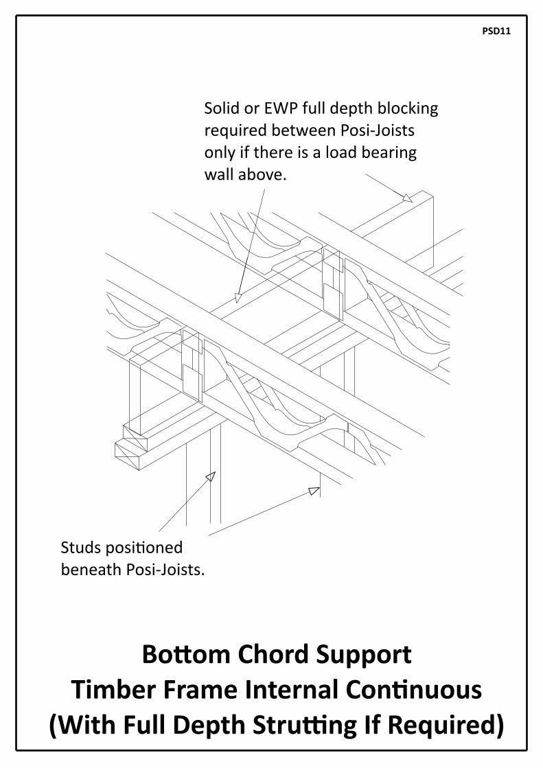
Bo om Chord SupportTimber Frame Internal Con nuous
(With Full Depth Stru ng If Required)
Solid or EWP full depth blockingrequired between Posi-Joistsonly if there is a load bearing wall above.
Studs posi oned beneath Posi-Joists.
PSD11

Bo om Chord Support Internal Masonry Lapped
Masonry built up to underside of oor toprovide restraint.
Note: Use on internal load bearing internal walls (not re walls).
Posi-Joists lapped over wall.
PSD12

Bo om Chord Support Internal Masonry Con nuous
or Bu ng Ends.
Masonry built up to underside of oor toprovide restraint.
(Minimum 45mm Bearing Required If Posi-Joist split on centre of wall.
PSD13

Bo om Chord Support Internal Masonry Con nuousJoist with solid mber block
Note: Use on internal load bearing internal walls (not re walls).
Solid mber block overbearing with grainparallel to span.
Gap to be lled toprovide air ghtness.
PSD14

Non-Loadbearing WallParallel with Posi-Joists.
Z clips.
38x89 C16 (min) noggins at max600mm centres.
Panel head restrainint nogging nailed down onto wall panel as above.
Wall panel skew nailed through onto support noggin with a min of 2 no 3.35 dia galvanised wire nails, length to suit.
PSD15

Wall panel skew nailed through onto noggin with a min of 2 no3.35 dia galvanised wire nails,length to suit.
Non-Loadbearing Par ons Parallel To Posi-Joists
(Alterna ve Noggin Support Detail)
PSD16
Plated stacked noggin supportedon top ofbo om chord ofPosi-Joists

Maximum Duct Sizes
RECTANGLE WIDTH
RECTANGLE DEPTH50 75 100 125 150 175 200 225 250 275 300
POSIJOISTSIZE
W CIRCLEDIA SQUARE
PS-8
PS-9
PS-10
PS-12
PS-14
PS-16
108 105 95
131 124 115
159 150 135
210 190 155
279 250 200
327 272 220
270 180 90
100180240310
320
350
490
510 470 430 390 340 300 260 220 170 130 90
60110160200
70110160
80160210270
310
440 390
260 210
350 300 250
--- - - - - -
-
-
-
-
---
-
- - -
- -
- - -
--
W
PSD17
LARGE SERVICES MAY NEED TO BE OF FLEXIBLE MATERIAL TO BE ABLE TO BE FED THROUGH
THE VOIDS IN THE POSI-JOISTS

Opening with 2-ply Posi-Joist Girderand Posi-Joist Trimmer Beam
Posi-Joist girder chords xedtogether as speci ed by design.
Do not notch bo om chordof Posi-Joist over bo om
ange of hanger.
PSD18
Posi-JoistHangers

Posi-Joist girder chords xedtogether as speci ed by design.
Do not notch bo om chordof Posi-Joist over bo om
ange of hanger.
Opening With 3 Ply Posi-Joist Girder and Posi-Joist Trimmer Beam
PSD19
Posi-JoistHangers
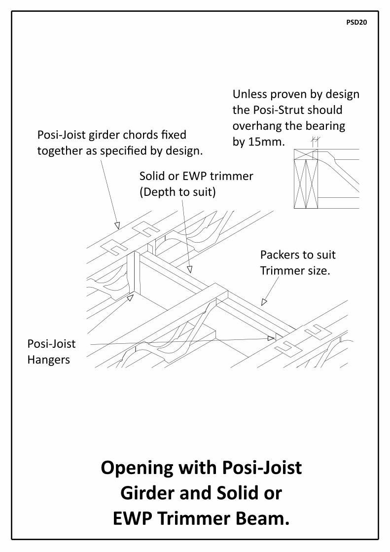
Opening with Posi-Joist Girder and Solid or
EWP Trimmer Beam.
Solid or EWP trimmer(Depth to suit)
Packers to suitTrimmer size.
Posi-Joist girder chords xedtogether as speci ed by design.
Unless proven by design the Posi-Strut shouldoverhang the bearingby 15mm.
PSD20
Posi-JoistHangers

Packers to suitTrimmer size.
Posi-Joist girder chords xedtogether as speci ed by design.
Staircase Opening With Posi-JoistGirder and Solid Timber
Trimmer Beam On Hangers
PSD21
Posi-JoistHangers

Posi-Joist girder chords xedtogether as speci ed by design.
Packers to suitTrimmer size.
PSD22
Staircase Opening With Solid Timber Or EWP Trimmer Beam Slo ed
Through Posi-Joist Girder
Packing piece topick up ceiling
Solid mber or EWPtrimmer at depth tosuit slo ed through
girders

Do not notch bo om chordof Posi-Joist over bo om
ange of hanger.
Staircase Opening With EWP Stair Trimmer and
Posi-Joist Trimmer beam
PSD23
Twice nail brace to web using3.1 x 75mm long galvanised wire nails
Posi-JoistHangers
Strongback securelyxed to trimmer with
suitable hanger

Strongback DetailFixed to Site Added Blocks
38x75 (min) blocks twice nailed to top and bo om members and twice nailed to strongback using3.1x75mm long galvanised ring shank nails.
Minimum recommended strongbacksizes are given above. See Posi-Joist calcula ons for EC5 oor designed sizes. Note:Using smaller sizes than speci ed will invalidate the design.
Posi on strongbacks ght to the underside of top chord.
(Fix at a maximum of 4.0 metre centres and within e ec ve zone)
INSERT STRONGBACK THROUGH POSI - JOISTSBEFORE FIXING AS IT CANNOT BE
INSTALLED AFTE THEY HAVE BEEN FIXED.
PSD24
WEB SIZE RECOMMENDED MINSTRONGBACK SECTION
PS-8, PS-9 & PS-10
PS12, PS-14 & PS16
47 x 97 TR26*
36 x 147 TR26*

Strongback DetailFixed To Built In Ver cal Webs
PSD25
(Fix at a maximum of 4.0 metre centres and within e ec ve zone)
INSERT STRONGBACK THROUGH POSI - JOISTSBEFORE FIXING AS IT CANNOT BE
INSTALLED AFTE THEY HAVE BEEN FIXED.
WEB SIZE
PS-8, PS-9 & PS-10
PS12, PS-14 & PS16
RECOMMENDED MINSTRONGBACK SECTION
47 x 97 TR26*
36 x 147 TR26*
Twice nail brace to web using3.1 x 75mm long galvanised wire nails
Minimum recommended strongbacksizes are given above. See Posi-Joist calcula ons for EC5 oor designed sizes. Note:Using smaller sizes than speci ed will invalidate the design.
Posi on strongbacks ght to the underside of top chord.

Twice nail brace to web using 3.1x75mm long galvanised wire nails.
Strongback BridgingFixed To Built In Ver cal Webs
PSD26
(Fix at a maximum of 4.0 metre centres and within e ec ve zone)
INSERT STRONGBACK THROUGH POSI - JOISTSBEFORE FIXING AS IT CANNOT BE
INSTALLED AFTE THEY HAVE BEEN FIXED.
WEB SIZE RECOMMENDED MINSTRONGBACK SECTION
PS-8, PS-9 & PS-10
PS12, PS-14 & PS16
47 x 97 TR26*
36 x 147 TR26*
Minimum recommended strongbacksizes are given above. See Posi-Joist calcula ons for EC5 oor designed sizes. Note:Using smaller sizes than speci ed will invalidate the design.
Posi on strongbacks ght to the underside of top chord.

38x75 (min) blocks twice nailed to top and bo om members and twice nailed to strongback using3.1x75mm long galvanised annular ringshank nails.
1200mm long splice xed with 10no3.1x90mm long galvanised annular ringshanknails each side of splice, nailed through and clenched over on far side.
Strongback SpliceFixed to Site Added Blocks
PSD27

Horizontal Restraint StrapFixed to Strongback
Strap xed along top edge of strongback.Refer to strap manufacturers details for
xing method.
Strongback twice nailed to brace using min 3.1x75mm long galvanised annular ringshanknails.
PSD28

Horizontal Restraint StrapFixed To Noggins
Strap xed to noggin. Refer to strapmanufacturers details for xing method.
Min 35 x 72 C16 noggin xed between joists.
PSD29

Horizontal Restraint StrapFixed to Con nuous Noggin
Strap xed along top edge of strongback.Refer to strap manufacturers details for
xing method.
35x97 C16 Noggin nailed to underside of top chord of Posi-Joist using 3.1x75mm long galvanised annular ringshank nails.
PSD29A

Typical Timber Frame Compartment Floor / Party Wall Detail
47x 89 Packsbetween joists
Posi-JoistsParallel to wall
Posi-Joistsbearing on wall
47x 89 Con nuous Pack
Floa ng Floor Comprising:-18mm T & G Chipboard on 19mm plasterboard plank on 25mm Fibreglass Slab on 18mm T & G Chipboard. All T & G edges glued, and 19mm plank bonded to chipboard with dabs of Gyproc sealant at 300mm centres. Joints between chipboard and plasterboard to be staggered and board direc on reversed.
Bead of sealent applied to oor deck proir to xing19mm plasterboard plank
100mm Mineral wool insula onquilt 23kb/m2
Mineral wool cavity barrier
2 no 30 x 200mm GMSStraps at 1200mm centres
Posi-web overbearing by min15mm
200approxFirst Posi-Joist beamset back from wallby approx 200mm
Plasterboard noggins
Ring Beams in solid mber or LVL
Ceiling (not shown) comprising:-2 Layers 15mm Gyproc Fireline Board on 16mm resilient bars at 400mmcentres. First layer xed with 38mm Gyproc screws at 230mm centres.Second layer xed with 60mm Gyproc screws at 230mm centres.Staggered with rst layer screws.Lay Firleline board in echelon pa ern with staggered joints.
PSD30

Fixing Round SVPusing Bearer Plates
Note: This may not perform well acous callyas sound will be transmi ed directly from the oor tothe bearer through the inner leaf of the wall.
Bearers xed to wall at oor and ceiling level.
Posi-Joist adjacent to SVP shown in full depth masonry hanger.
Soil Vent Pipe (SVP).
PSD31

Soil Vent Pipe (SVP).
Packer
Face Fix Joist Hanger(Solid Trimmer to Posi-Joist)
Solid Trimmer to built into wall.
Fixing Round SVPusing Solid Trimmer.
PSD32
Unless proven by design the Posi-Strut should overhang thebearing by 15mm

Side eleva on
65
330mm
330mm
5555
130 maxTrim
47
GrainDirec on
PSD33
47
55 55
330mm solid block from dry well seasoned mber
ght xed at manufacture
For 72 or 97 wide Posi joists insert one trimmable block secured with 6 no. 3.1 x 90 long power driven annular ring-shank or 3.3 x 98 long power
driven screw-shank nails into the top and 6 into the bo om at 44mm centres.
Plan view of Posi-Joist with one block
Two blocks required when chords are
122mm or 147mm
Plan view of Posi-Joist with two blocks
Site Trimmable Block End Support Detail
For 122 and 147 wide Posi joists insert two trimmable blocks secured with 12 no. 3.1 x 90 long power driven annular ring-shank or helically twisted nails
into the top and 12 into the bo om at 44mm centres.
One block required when chords are72mm or 97mm
Min 200
130 max Trim
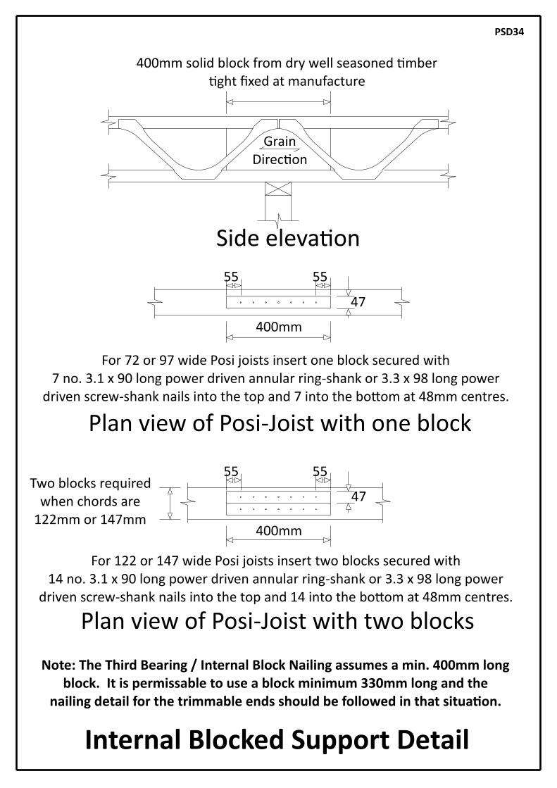
Internal Blocked Support Detail
Side eleva on
400mm solid block from dry well seasoned mberght xed at manufacture
PSD34
GrainDirec on
400mm
400mm
47
Plan view of Posi-Joist with one block
Plan view of Posi-Joist with two blocks
47
55 55
For 72 or 97 wide Posi joists insert one block secured with 7 no. 3.1 x 90 long power driven annular ring-shank or 3.3 x 98 long power
driven screw-shank nails into the top and 7 into the bo om at 48mm centres.
Two blocks required when chords are
122mm or 147mm
55 55
For 122 or 147 wide Posi joists insert two blocks secured with 14 no. 3.1 x 90 long power driven annular ring-shank or 3.3 x 98 long power
driven screw-shank nails into the top and 14 into the bo om at 48mm centres.
Note: The Third Bearing / Internal Block Nailing assumes a min. 400mm long block. It is permissable to use a block minimum 330mm long and the
nailing detail for the trimmable ends should be followed in that situa on.
Recommended