Cat. Nº: ABOX-104-001-71
USER GUIDE
PLC Arduino ARDBOX 20 I/Os Relay HF

Pag
e2
Cat. Nº: ABOX-104-001-71

Pag
e3
Cat. Nº: ABOX-104-001-71
PLC Arduino ARDBOX 20 I/Os Relay HF User Guide Revised March 2018
This user guide is for version PLC Arduino ARDBOX 20 I/Os Relay HF,
with Reference name Ref.IS.AB20REL-HF only. For older versions refer
to user guide with Cat. No. ABOX-004-001-70

Pag
e4
Cat. Nº: ABOX-104-001-71
Preface
This User Guide is been implemented by Boot & Work, S.L. working
under the name Industrial Shields.
Purpose of the manual
The information contained in this manual can be used as a reference to operating, to functions, and to the technical data of the signal modules, power supply modules and interface modules.
Intended Audience
This User Guide is intended for the following audience:
Persons in charge of introducing automation devices.
Persons who design automation systems.
Persons who install or connect automation devices.
Persons who manage working automation installation.
Warnings:
Unused pins should not be connected. Ignoring the directive may damage the
controller.
Improper use of this product may severely damage the controller.
Refer to the controller’s User Guide regarding wiring considerations.
Before using this product, it is the responsibility of the user to read the product’s User
Guide and all accompanying documentation.

Pag
e5
Cat. Nº: ABOX-104-001-71
Application Considerations and Warranty
Read and Understand this Manual
Please read and understand this manual before using the product. Please consult your
comments or questions to Industrial Shields before using the product.
Application Consideration
THE PRODUCTS CONTAINED IN THIS DOCUMENT ARE NOT SAFETY RATED.
THEY SHOULD NOT BE RELIED UPON AS A SAFETY COMPONENT OR
PROTECTIVE DEVICE FOR ENSURING SAFETY OF PERSONS, AS THEY ARE
NOT RATED OR DESSIGNED FOR SUCH PURPOSES.
Please know and observe all prohibitions of use applicable to the products.
FOR AN APPLICATION INVOLVING SERIOUS RISK TO LIFE OR PROPERTY
WITHOUT ENSURING THAT THE SYSTEM AS A WHOLE HAS BEEN DESSIGNED
TO ADDRESS THE RISKS, NEVER USE THE INDUSTRIAL SHIELDS PRODUCTS.
NEVER USE THE INDUSTRIAL SHIELDS PRODUCTS BEFORE THEY ARE
PROPERLY RATED AND INSTALLED FOR THE INTENDED USE WITHIN THE
OVERALL EQUIPMENT OR SYSTEM.
Industrial Shields shall not be responsible for conformity with any codes, regulations or
standards that apply to the combination of products in the customer’s application or use
of the product.
The following are some examples of applications for which particular attention must be
given. This is not intended to be an exhaustive list of all possible uses of the products,
nor is it intended to imply that the uses may be suitable for the products:
Systems, machines, and equipment that could present a risk to life or property.
Nuclear energy control systems, combustion systems, railroad systems,
aviation systems, medical equipment, amusement machine, vehicles, safety
equipment, and installation subject to separate industry or government
regulations.
Outdoor use, uses involving potential chemical contamination or electrical
interference, or conditions or uses not described in this document.
At the customer’s request, INDUSTRIAL SHIELDS will provide applicable third party
certification documents identifying ratings and limitations of use that apply to the
products. This information by itself is not sufficient for a complete determination of the
suitability of the products in combination with the system, machine, end product, or
other application or use.

Pag
e6
Cat. Nº: ABOX-104-001-71
Disclaimers
Weights and Dimensions
Dimensions and weights are nominal and they are not used for manufacturing
purposes, even when tolerances are shown.
Performance Data
Performance data given in this manual is provided as a guide for the user in
determining suitability and does not constitute a warranty. It may represent the result of
INDUSTRIAL SHIELDS’s test conditions, and the users most correlate it to actual
application requirements. Actual performance is subject to the INDUSTRIAL SHIELDS
Warranty and Limitations of Liability.
Change in Specifications
Product specifications and accessories may be changed at any time based on
improvements and other reasons.
It is our practice to change model numbers when features are changed, or published
ratings or when significant construction changes are made. However, some
specifications of the products may be changed without any notice. When in doubt,
special numbers may be assigned to fix or stablish key specifications for your
application on your request. Please consult with your INDUSTRIAL SHIELDS
representative at any time to confirm actual specifications of purchased products.
Errors and Omissions
The information in this document has been carefully checked and is believed to be
accurate; however, no responsibility is assumed for clerical, typographical, or
proofreading errors, or omissions.

Pag
e7
Cat. Nº: ABOX-104-001-71
Warranty and Limitations of Liability
Warranty
Industrial Shields’s exclusive warranty is that the products are free from defects in
materials and workmanship for a period of one year (or other period if specified) from
date of sale by Industrial Shields.
INDUSTRIAL SHIELDS MAKES NO REPRESENTATION OR WARRANTY, EXPRESS
OR IMPLIED, REGARDING MERCHANABILITY, NON-INFRINGEMENT, OR
FITNESS FOR PARTICULAR PURPOSE OF THE PRODUCTS. ANY BUYER OR
USER ACKNOWLEDGES THAT THE BUYER OR USER ALONE HAS DETERMINED
THAT THE PRODUCTS WILL SUITABLY MEET THE REQUIREMENTS OF THEIR
INTENDED USE. INDUSTRIAL SHIELDS DISCLAIMS ALL OTHER WARRANTIES,
EXPRESS OR IMPLIED
Limitations of Liability
INDUSTRIAL SHIELDS SHALL NOT BE RESPONSIBLE FOR SPECIAL, INDIRECT,
OR CONSEQUENTIAL DAMAGES, LOSS OF PROFITS OR COMERCIAL LOSS IN
ANY WAY CONNECTED WITH THE PRODUCTS, WHETHER SUCH CLAIM IS
BASED ON CONTRACT, WARRANY, NEGLIGENCE, OR STRICT LIABILITY.
If no event shall the responsibility of INDUSTRIAL SHIELDS for any act exceed the
individual price of the product on which liability is asserted.
IN NO EVENT SHALL INDUSTRIAL SHIELDS BE RESPONISBLE FOR WARRANTY,
REPAIR OR OTHER CLAIMS REGARDING THE PRODUCTS UNLESS INDUSTRIAL
SHIELDS’S ANALYSIS CONFIRMS THAT THE PRODUCTS WERE PROPERLY
HANDLED, STORED, INSTALLED, AND MAINTAINED AND NOT SUBJECT TO
CONTAMINATION, ABUSE, MISUSE, OR INAPPROPIATE MODIFICATION OR
REPAIR.
Pag
e8
Cat. Nº: ABOX-104-001-71
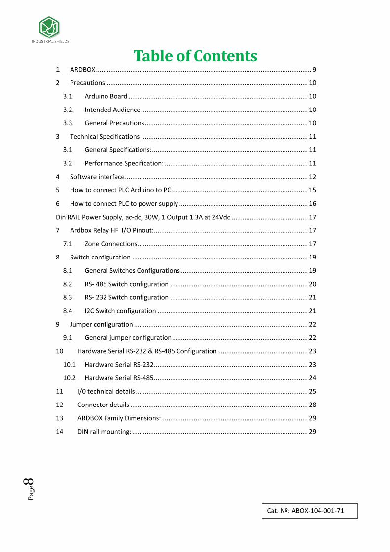
Table of Contents 1 ARDBOX ....................................................................................................................... 9
2 Precautions ................................................................................................................ 10
3.1. Arduino Board ................................................................................................... 10
3.2. Intended Audience ............................................................................................ 10
3.3. General Precautions .......................................................................................... 10
3 Technical Specifications ............................................................................................ 11
3.1 General Specifications: ...................................................................................... 11
3.2 Performance Specification: ............................................................................... 11
4 Software interface ..................................................................................................... 12
5 How to connect PLC Arduino to PC ........................................................................... 15
6 How to connect PLC to power supply ....................................................................... 16
Din RAIL Power Supply, ac-dc, 30W, 1 Output 1.3A at 24Vdc .......................................... 17
7 Ardbox Relay HF I/O Pinout: ..................................................................................... 17
7.1 Zone Connections .............................................................................................. 17
8 Switch configuration ................................................................................................. 19
8.1 General Switches Configurations ...................................................................... 19
8.2 RS- 485 Switch configuration ............................................................................ 20
8.3 RS- 232 Switch configuration ............................................................................ 21
8.4 I2C Switch configuration ................................................................................... 21
9 Jumper configuration ................................................................................................ 22
9.1 General jumper configuration ........................................................................... 22
10 Hardware Serial RS-232 & RS-485 Configuration .................................................. 23
10.1 Hardware Serial RS-232 ..................................................................................... 23
10.2 Hardware Serial RS-485 ..................................................................................... 24
11 I/0 technical details ............................................................................................... 25
12 Connector details .................................................................................................. 28
13 ARDBOX Family Dimensions: ................................................................................. 29
14 DIN rail mounting: ................................................................................................. 29

Pag
e9
Cat. Nº: ABOX-104-001-71
1 ARDBOX
A compact PLC based in Open Source Hardware technology. With different
Input/Outputs Units.
COMPACT PLC ARDUINO ARDBOX 20 I/Os RELAY HF
Alimentation Voltage 12 to 24Vdc Fuse protection (2.5A)
Polarity protection
Max. current consumption 1,5A
Size 100x45x115
Clock Speed 16MHz
Flash Memory 32KB of which 4KB are used by
bootloader
SRAM 2.5KB
EEPROM 1KB
Communications I2C – USB -- RS232 -- RS485 –
SPI
TOTAL Input points 10
TOTAL Output points 10
INPUTS
Digital range:5 to 24 Vdc (3.8 to
25.4 Vdc)
Analog range: 0 to 10 Vdc
Digital 10
5 to 24Vdc
I min: 3/6 mA Separated PCB ground
Analog 10 bits 6 of 10 Digital input
0 to10V
Input Impedance: 39K Separated PCB ground
* Interrupt HS 4 of 10 Digital input
5 to 24Vdc
Pag
e10
Cat. Nº: ABOX-104-001-71
2 Precautions
3.1. Arduino Board All Ardbox family products use Arduino LEONARDO Board.
3.2. Intended Audience This manual is intended for technicians, which must have knowledge of electrical
systems.
3.3. General Precautions The user must operate the product according to the performance specifications
described in the operation manuals.
Before using the product under conditions, which are not described in the manual or
applying the product to nuclear control systems, railroad systems, aviation systems,
vehicles, combustion systems, medical equipment, amusement machines, safety
equipment and other systems, machines, and equipment that may have a serious
influence on lives and property if used improperly, consult your INDUSTRIAL SHIELDS
representative.
Make sure that the rating and performance characteristics of the product are sufficient
for the systems, machines, and equipment, and be sure to provide the systems,
machines, and equipment with double safety mechanisms.
This manual provides information for programming and operating the Unit. Be sure to
read this manual before attempting to use the Unit keep this manual close at hand for
reference during operation.
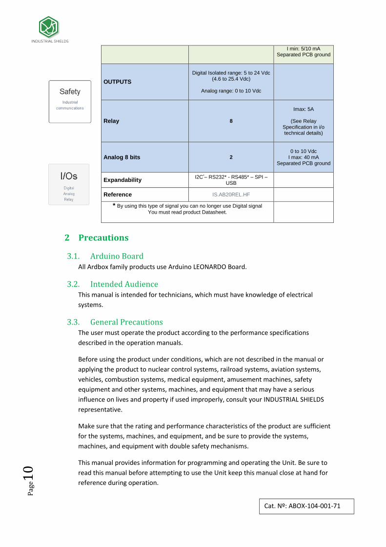
I min: 5/10 mA Separated PCB ground
OUTPUTS
Digital Isolated range: 5 to 24 Vdc
(4.6 to 25.4 Vdc)
Analog range: 0 to 10 Vdc
Relay 8
Imax: 5A
(See Relay
Specification in i/o technical details)
Analog 8 bits 2
0 to 10 Vdc
I max: 40 mA Separated PCB ground
Expandability I2C*– RS232* - RS485* – SPI –
USB
Reference IS.AB20REL.HF
* By using this type of signal you can no longer use Digital signal
You must read product Datasheet.

Pag
e11
Cat. Nº: ABOX-104-001-71
3 Technical Specifications
3.1 General Specifications:
Power supply voltage
DC power supply 12 to 24Vdc
Operating voltage range
DC power supply 11.4 to 25.4Vdc
Power consumption
DC power supply 30VAC max.
External power supply
Power supply voltage 12 to 24Vdc
Power supply output capacity
1.3A
Insulation resistance 20MΩ min.at 500Vdc between the AC terminals and the protective earth terminal.
Dielectric strength 2.300 VAC at 50 to 60 HZ for one minute with a leakage current of 10mA max. Between all the external AC terminals and the protective earth terminal.
Shock resistance 80m/s2 in the X, Y and Z direction 2 times each.
Ambient temperature (operating) 0º to 45ºC
Ambient humidity (operating) 10% to 90% (no condensation)
Ambient environment (operating) With no corrosive gas
Ambient temperature (storage) -20º to 60ºC
Power supply holding time 2ms min.
Weight 340g max.
3.2 Performance Specification:
Arduino Board ARDUINO LEONARDO
Control method Stored program method
I/O control method Combination of the cyclic scan and immediate refresh processing methods.
Programming language Arduino IDE. Based on wiring (Wiring is an Open Source electronics platform composed of a programming language. “similar to the C”. http://arduino.cc/en/Tutorial/HomePage
Microcontroller ATmega32u4
Pag
e12
Cat. Nº: ABOX-104-001-71
Flash Memory 32kb of which 4 kb are used by bootloader
Program capacity (SRAM) 2.5kb
EEPROM 1kb
Clock Speed 16MHz
4 Software interface Industrial Shields PLC are programmed using Arduino IDE, which is a software based on the C
language. They can also be programmed using directly C but it is much easier working with
Arduino IDE as it provides lots of libraries that helps in the programming.
Furthermore Industrial Shields provides boards for programming the PLCs much easier.
Basically it is no needed to define the pins and if that pins are inputs or outputs. Everything is
set up automatically if using the boards.
In order to install Industrial Shields boards, these are the steps that must be followed.
Requirements:
Arduino IDE 1.8.0 or above (better to have always the latest version).
Steps:
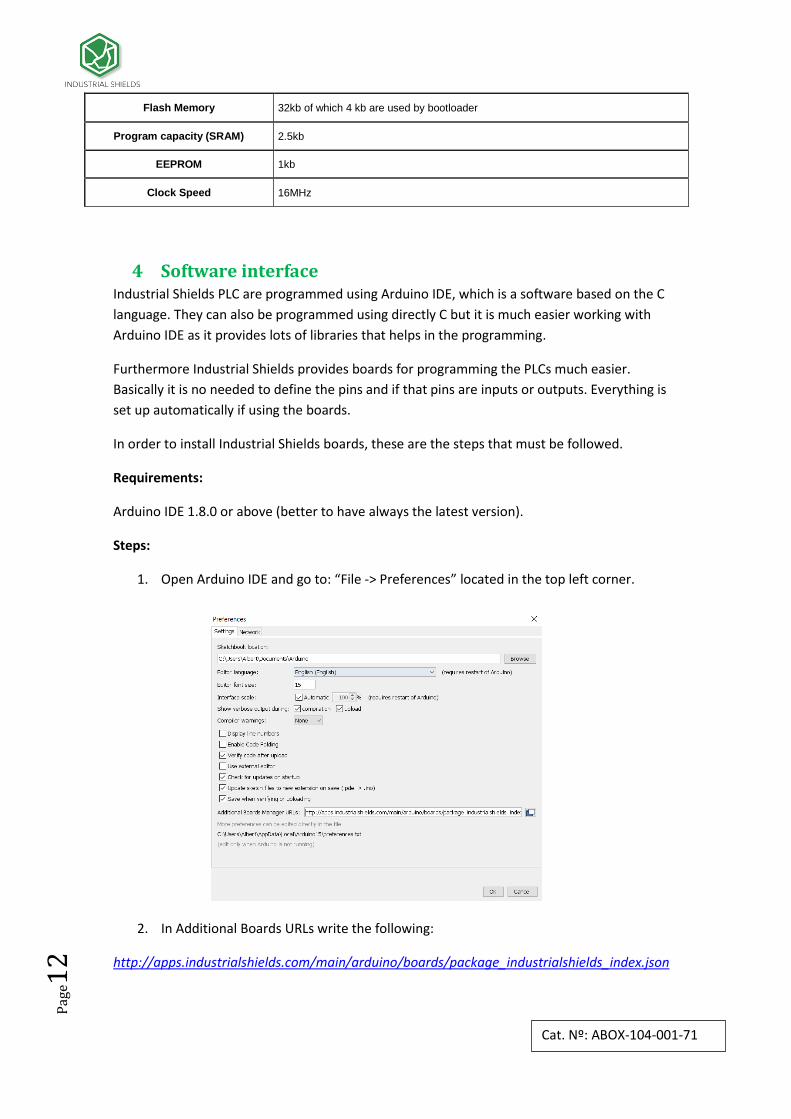
1. Open Arduino IDE and go to: “File -> Preferences” located in the top left corner.
2. In Additional Boards URLs write the following:
http://apps.industrialshields.com/main/arduino/boards/package_industrialshields_index.json

Pag
e13
Cat. Nº: ABOX-104-001-71
3. Press OK to save the changes.
4. Go to: Tools -> Board: … -> Boards Manager
5. Search for industrialshields on the searcher.
6. Click install (selecting the latest version).
Following this steps you will be able to use now the Industrial Shields Boards:

Pag
e14
Cat. Nº: ABOX-104-001-71
Once it is selected the Ardbox Family or M-Duino family an extra option will appear on Tools:
There, it can be selected the exact model for every family.
Also there are some examples of programming in File -> Examples -> Ardbox Family.
Furthermore there are some extra libreries that can be found in Industrial Shields github.
https://github.com/IndustrialShields/

Pag
e15
Cat. Nº: ABOX-104-001-71
5 How to connect PLC Arduino to PC
- Connect USB port from PLC to PC.
NOTE: Ardbox Family use micro USB cable.
- Open Arduino IDE interface:
- Select Industrial Shields boards -> Ardbox Family
- Select the correct Ardbox Relay Board.
If it is used the latest version of Industrial Shields boards it will appear 4 different Ardbox Relay boards: The ones that have to be used for the 104-001-71 Ardbox Relay HF are the following ones:
Ardbox Relay HF w/ HW RS-485
Ardbox Relay HF w/ HW RS-232
* HW is the abbreviation of Hardware, so depending on the Hardware Serial it will be used, it is needed to select one or the other. See section 11 to configure the equipment to work with RS-232 Hardware Serial or RS-485 Hardware Serial. If it is not used the RS-232 & RS-485 it is needed to select the board Ardbox Relay HF w/ HW RS-485. See section 9-10 to enable the features that are disabled if using RS-485 protocol that will get enabled as there is no RS protocol.

Pag
e16
Cat. Nº: ABOX-104-001-71
- Select correct port.
Now everything is set up to upload a sketch to Ardbox Relay HF
6 How to connect PLC to power supply
- Ardbox Family PLCs are 12 to 24Vdc supplied. IMPORTANT: The polarity IS NOT
REVERSAL!
- Make sure that the live and GND connector of the power supply match the PLC.
- Make sure that the power supply mains output is not higher than 24Vdc.
Pag
e17
Cat. Nº: ABOX-104-001-71
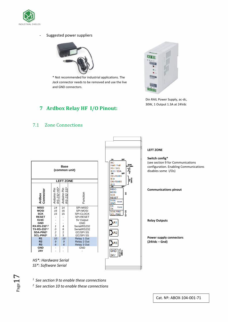
- Suggested power suppliers
7 Ardbox Relay HF I/O Pinout:
7.1 Zone Connections
HS*: Hardware Serial SS*: Software Serial
1 See section 9 to enable these connections 2 See section 10 to enable these connections
Base
(common unit)
LEFT ZONE
Ard
bo
x
Co
nn
ecto
r
Ard
uin
o P
in
RS
-232 H
S*
Ard
uin
o P
in
RS
-232 S
S*
Fu
nctio
n
MISO MOSI SCK
RESET 5VdC GND
RX-RS-2321,2 TX-RS-2321,2 SDA-PIN21 SCL-PIN31
R1 R2 R3
GND 24V
14 16 15 -
- - 1 0 2 3 10 9 6 - -
14 16 15 - - - 4 8 2 3 10 9 6 - -
SPI-MISO SPI-MOSI
SPI-CLOCK SPI-RESET 5V Output
GND Serial/RS232 Serial/RS232 I2C/SPI SS I2C/SPI SS Relay 1 Out Relay 2 Out Relay 3 Out
GND -
* Not recommended for industrial applications. The
Jack connector needs to be removed and use the live
and GND connectors.
LEFT ZONE Switch config* (see section 9 for Communications configuration. Enabling Communications disables some I/Os)
Communications pinout
Relay Outputs
Power supply connectors (24Vdc – Gnd)
Din RAIL Power Supply, ac-dc,
30W, 1 Output 1.3A at 24Vdc

Pag
e18
Cat. Nº: ABOX-104-001-71
Base
(common unit)
RIGHT ZONE
Ard
bo
x
Co
nn
ecto
r
Ard
uin
o P
in
RS
-485 H
D*
Ard
uin
o P
in
RS
-485 F
D*
Fu
nctio
n
B-
A+
Z-/A0.1
Y+/A0.0
R4
R5
I0.9
I0.8
I0.7
I0.6
I0.51
I0.41
I0.32
I0.22
I0.1
I0.01
R6
R71
R81
-
-
11
13
5
3
A5
A4
A3
A2
A1
A0
8
4
12
2
7
0
1
-
-
-
-
5
3
A5
A4
A3
A2
A1
A0
8
4
12
2
7
0
1
RS485
RS485
RS485/Analog Output
RS485/Analog Output
Relay 4 Out
Relay 5 Out
Analog/Digital Input
Analog/Digital Input
Analog/Digital Input
Analog/Digital Input
Analog/Digital Input
Analog/Digital Input
Digital Input/ Interrupt
Digital Input/ Interrupt
Digital Input/ Interrupt
Digital Input/ Interrupt
Relay 6 Out
Relay 7 Out
Relay 8 Out
Power LED Arduino Reset button Input / Output LED
RIGHT ZONE RS-485 pinout Analog Outputs Pinout Relay Outputs
Inputs pinout
Relay Outputs
Config switch * (see section 9 for communications configuration)

Pag
e19
Cat. Nº: ABOX-104-001-71
8 Switch configuration
8.1 General Switches Configurations LEFT ZONE. Communications and inputs/outputs can not work simultaneously.
1. NC – Not Connected
2. H/F – Choosing between Half/Full Duplex for the RS485 communication. In order to use Full Duplex, it has to be considered the TOP ZONE and the JUMPER ZONE(*see section 10).
3. SCL/R5 – Choosing between SCL (I2C) and R5. If the switch is ON, the R5 will be enabled and the SCL will be disabled. If the switch is OFF, SCL will be now enabled and R5 disabled.
4. SDA/I0.0 - Choosing between SDA (I2C) and I0.0. If the switch is ON, the I0.0 will be enabled and the SDA will be disabled. If the switch is OFF, SDA will be now enabled and R5 disabled.
1. RE-RS485 – If this switch is ON, the I0.4 switch must be set to OFF. Being in ON mode it enables
RE for the RS-485.
2. I0.4 – If this switch is ON, the RE-RS485 switch must be set to OFF. Being in ON mode it enables
the input I0.4.
3. DE-RS485 – If this switch is ON, the I0.5 switch must be set to OFF. Being in ON mode it
enables DE for the RS-485.
4. I0.5 – If this switch is ON, the DE-RS485 switch must be set to OFF. Being in ON mode it
enables the input I0.5.
TOP ZONE. Communications and outputs can not work simultaneously.
LEFT ZONE
SWITCH ON OFF
NC - -
H/F Half Duplex Full Duplex
SCL/R5 R5 SCL
SDA/I0.0 I0.0 SDA
RE-RS485 RE-RS485 I0.4
I0.4 I0.4 RE-RS485
DE-RS485 DE-RS485 I0.5
I0.5 I0.5 DE-RS485
TOP ZONE
SWITCH ON OFF
D1 - RS-485 RS-232/485 R8
R8 R8 RS-232/485
D0 - RS-485 RS-232/485 R7
R7 R7 RS-232/485

Pag
e20
Cat. Nº: ABOX-104-001-71
1. D1 – RS-485: If this switch is ON, the R8 switch must be set to OFF. Being in ON mode it enables DI for the RS-485 and RS-232 Hardware Serial ( see section 9 for jumper configuration)
2. R8: If this switch is ON, the DI – RS-485 switch must be set to OFF. Being in ON mode it enables the Relay 8.
3. D0 – RS-485: If this switch is ON, the R7 switch must be set to OFF. Being in ON mode it enables D0 for the RS-485 or RS-232 Hardware Serial ( see section 9 for jumper configuration)
4. R7: If this switch is ON, the D0 – RS-485 switch must be set to OFF. Being in ON mode it enables the Relay 7.
8.2 RS- 485 Switch configuration
RS-485 TOP ZONE: In order to enable the RS-485 protocol the
TOP ZONE must be configured as it is shown in the table.
Although the switch name only is referenced to RS-485 it is
also the same for the RS-232.
Having this set up, the R7 & R8 are disabled.
RS-485 LEFT ZONE: The H/F can be set up as ON or OFF. If it is wished
to use the RS-485 Half Duplex (A+, B-) it has to be ON. For using the
RS-485 Full Duplex (A+, B-, Y+, Z-) it has to be OFF.
The switch RE-RS485 and DE-RS485 must be set in ON mode. As
these pins are set to ON, the other 2 (I0.4, I0.5) must be set to OFF.
Being in OFF mode they are completely disabled.
The switches marked as “ – “ don’t interfere with the RS-485
communication protocol.
* To enable the RS-485 communication it is needed to configure also the jumpers, see Section 10
TOP ZONE
SWITCH MODE
DI - RS-485 ON
R8 OFF
D0 - RS-485 ON
R7 OFF
LEFT ZONE
SWITCH MODE
NC -
H/F ON/OFF
SCL/R5 -
SDA/I0.0 -
RE-RS485 ON
I0.4 OFF
DE-RS485 ON
I0.5 OFF

Pag
e21
Cat. Nº: ABOX-104-001-71
8.3 RS- 232 Switch configuration
RS-232 TOP ZONE: In order to enable the RS-232 protocol the
TOP ZONE must be configured as it is shown in the table.
Although the switch name only is referenced to RS-485 it is
also the same for the RS-232.
Having this set up, the R7 & R8 are disabled.
RS-232 LEFT ZONE: As both RS-232 & RS-485 can’t work at the same
time, the RE-RS485 and DE-RS485 have to be in OFF mode, so this
enables the I0.4, I0.5 inputs.
* To enable the RS-232 communication it is needed to configure also the jumpers, see Section 10
8.4 I2C Switch configuration
To enable I2C configuration the switches SCL/R5 & SDA/I0.0 must be set to ON. As they are in
ON mode R5 & I0.0 are disabled.
The switches marked as “ – “ don’t interfere with the I2C communication protocol.
TOP ZONE
SWITCH MODE
DI - RS-485 ON
R8 OFF
DO - RS-485 ON
R7 OFF
LEFT ZONE
SWITCH MODE
NC -
H/F -
SCL/R5 -
SDA/I0.0 -
RE-RS485 OFF
I0.4 ON
DE-RS485 OFF
I0.5 ON
TOP ZONE
SWITCH MODE
DI - RS-485 -
R8 -
DO - RS-485 -
R7 -
LEFT ZONE
SWITCH MODE
NC -
H/F -
SCL/R5 ON
SDA/I0.0 ON
RE-RS485 -
I0.4 -
DE-RS485 -
I0.5 -

Pag
e22
Cat. Nº: ABOX-104-001-71
9 Jumper configuration
9.1 General jumper configuration
This jumper zone makes the selection between using the RS-485 Full Duplex or the Analog Outputs. If it is wanted to use the RS-485 Full Duplex communication protocol the Y+ must be connected to ENABLE, and Z- also connected to ENABLE. If it is wanted to use the Analog Outputs, The A0.0 must be connected to ENABLE, and A0.1 also connected to Enable This jumper zone makes the choosing between connecting the inputs I0.2, I0.3 to pins 4, 8 of the Arduino Leonardo respectively, or connect the RS-232 ports to activate the Software Serial RS-232. In order to use the inputs I0.2,I0.3 the jumper must be connected to the pins 4,8. So I0.2 must be connected with D4 and I0.3 must be connected to D8. This jumper makes the choosing between connecting MAX232 to pins 0,1 of the Arduino Leonardo or with the MAX485. In order to use the RS-232 Hardware Serial protocol both RS-232 must be connected to the D1/D0. In order to use the RS-485 Hardware Serial protocol both
RS-485 must be connected to the D1/D0. *The jumpers that are not connected to the middle jumpers MUST NOT be connected anywhere.
JUMPER ZONE 1
LEFT RIGHT
Y+ Z-
ENABLE ENABLE
A0.0 A0.1
JUMPER ZONE 2
LEFT RIGHT
I0.2 I0.3
D4 D8
RS-232 RS-232
JUMPER ZONE 3
UP RS-485 D1 RS-232
DOWN RS-485 D0 RS-232
Pag
e23
Cat. Nº: ABOX-104-001-71
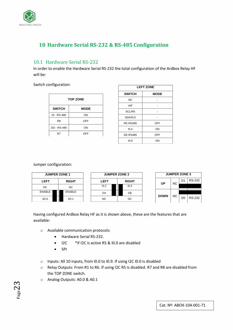
10 Hardware Serial RS-232 & RS-485 Configuration
10.1 Hardware Serial RS-232 In order to enable the Hardware Serial RS-232 the total configuration of the Ardbox Relay HF
will be:
Switch configuration:
Jumper configuration:
Having configured Ardbox Relay HF as it is shown above, these are the features that are
available:
o Available communication protocols:
Hardware Serial RS-232.
I2C *If I2C is active R5 & I0.0 are disabled
SPI
o Inputs: All 10 inputs, from I0.0 to I0.9. If using I2C I0.0 is disabled
o Relay Outputs: From R1 to R6. If using I2C R5 is disabled. R7 and R8 are disabled from
the TOP ZONE switch.
o Analog Outputs: A0.0 & A0.1
LEFT ZONE
SWITCH MODE
NC -
H/F -
SCL/R5 -
SDA/I0.0 -
RE-RS485 OFF
I0.4 ON
DE-RS485 OFF
I0.5 ON
TOP ZONE
SWITCH MODE
DI - RS-485 ON
R8 OFF
DO - RS-485 ON
R7 OFF
JUMPER ZONE 1
LEFT RIGHT
NC NC
ENABLE ENABLE
A0.0 A0.1
JUMPER ZONE 2
LEFT RIGHT
I0.2 I0.3
D4 D8
NC NC
JUMPER ZONE 3
UP NC D1
RS-232
DOWN NC
D0
RS-232

Pag
e24
Cat. Nº: ABOX-104-001-71
10.2 Hardware Serial RS-485
In order to enable the Hardware Serial RS-485 the total configuration of the Ardbox Relay HF
will be:
Switch configuration:
Jumper configuration:
Having configured Ardbox Relay HF as it is shown above, these
are the features that are available:
o Available communication protocols:
Hardware Serial RS-485.
I2C *If I2C is actived R5 & I0.0 are disabled
SPI
o Inputs: All 10 inputs except for input I0.4, I0.5 as they are disabled from the LEFT ZONE
switch. If using I2C I0.0 is disabled
o Relay Outputs: From R1 to R6. If using I2C R5 is disabled. R7 and R8 are disabled from
the TOP ZONE switch.
o Analog Outputs: A0.0 & A0.1 if RS-485 is working in Half Duplex. They are disabled if
using RS-485 Full Duplex, see the JUMPER ZONE 1 from above.
LEFT ZONE
SWITCH MODE
NC -
H/F ON/OFF
SCL/R5 -
SDA/I0.0 -
RE-RS485 ON
I0.4 OFF
DE-RS485 ON
I0.5 OFF
TOP ZONE
SWITCH MODE
DI - RS-485 ON
R8 OFF
DO - RS-485 ON
R7 OFF
JUMPER ZONE 1 HALF DUPLEX
LEFT RIGHT
Y+ Z-
ENABLE ENABLE
A0.0 A0.1
JUMPER ZONE 2
LEFT RIGHT
I0.2 I0.3
D4 D8
NC NC
JUMPER ZONE 3
UP NC D1
RS-232
DOWN NC
D0
RS-232
JUMPER ZONE 1 FULL DUPLEX
LEFT RIGHT
Y+ Z-
ENABLE ENABLE
A0.0 A0.1

Pag
e25
Cat. Nº: ABOX-104-001-71
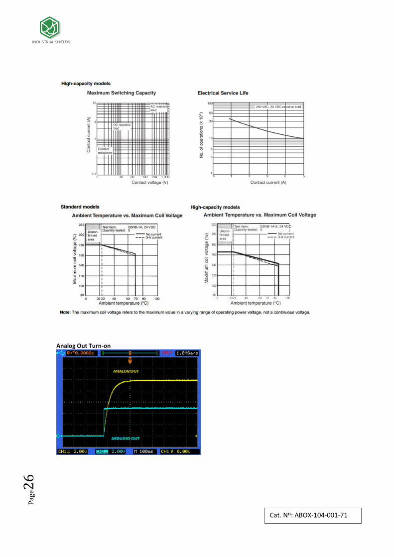
11 I/0 technical details Relay
Pag
e26
Cat. Nº: ABOX-104-001-71
Analog Out Turn-on

Pag
e27
Cat. Nº: ABOX-104-001-71
Analog Out Turn-off
Analog/Digital Input Turn-on
Analog/Digital Input Turn-off

Pag
e28
Cat. Nº: ABOX-104-001-71
12 Connector details
The connector inside the PLCs that mounts on the PCB is MC 0,5/10-G-2,5 THT – 1963502
from Phoenix contact. MC0,5/10-G-2,5THT
For I/O and power supply there is a FK-MC 0,5/10-ST-2,5 - 1881406 connector from Phoenix
contact. FK-MC 0,5/10-ST-2,5
Connection details:
Article reference MC 0,5/10-G-2,5 THT
Height 8,1mm
Pitch 2,5mm
Dimension 22,5mm
Pin dimensions 0,8x0,8mm
Pin spacing 2,50mm
Article reference FK-MC 0,5/10-ST-2,5
Rigid conduit section min. 0,14 mm²
Rigid conduit section max. 0,5 mm²
Flexible conduit section min. 0,14 mm²
Flexible conduit section max. 0,5 mm²
Conduit section AWG/kcmil min. 26
Conduit section AWG/kcmil max. 20

Pag
e29
Cat. Nº: ABOX-104-001-71
13 ARDBOX Family Dimensions:
45mm width
14 DIN rail mounting:

Pag
e30
Cat. Nº: ABOX-104-001-71
About Industrial Shields: Direction: Fàbrica del Pont, 1-11
Zip/Postal Code: 08272
City: Sant Fruitós de Bages (Barcelona)
Country: Spain
Telephone: (+34) 938 760 191 / (+34) 635 693 611
Mail: [email protected]
Recommended