Plasma Focusing:Opportunities and Challenges
Johnny S.T. NgSLAC National Accelerator Center
ICFA Workshop on Novel Concepts for Linear Accelerators and CollidersSLAC, July 8, 2009

Outline
• Introduction: Overview and Motivation• Experimental Results• Challenges
– Emittance preservation– Collider application: detector background
• Summary

Plasma lens focusing for linear colliders
The plasma electron densityrelative to the beam electrondensity will determine the locationof the return current.
An electron beamtraversing a plasma
In vacuum, there is no netLorentz force on the beam
In a plasma, E-field is neutralized;B-field pinches the beam.
[Pisin Chen, Part. Accel., 20, 171 (1987)]

J. Ng, ICFA Workshop July 2009
Review: Plasma Focusing[P. Chen, in Handbook of Acc. Phys. and Eng., p484]
Superdensenp >> nb
Overdensenp > nb,
SLAC E-150[J.Ng et al,PRL 2001]
Underdense(np < nb)SLAC-E157and E164x[e.g., P. Muggliet al PRL2008]
UCLA/FNPL,[Thompson etal PAC07]
Regimes: Beam OpticsFocusing StrengthFocusing mechanism
Return current penetrates beam volume;both beam fields (magnetic and electric)largely cancelled; self-focusingdiminishes.
- Thin lens considered.- Aberration power:
-Courant-Snyder parameters:
-Reduction in spot size:
-Plasma fully neutralize space chargeof the beam while the return currentruns outside of the beam volume
-Beam’s magnetic field leads to self-focusing
-Thick lens considered.
-Maximum reduction:
e-: total rarefaction, ions providenearly linear focusing.
e+: excess plasma electrons andcurrent pull positrons inward
1rpk
pe
enrK 2
pe
e nrK 8
be nrK 2
2)(12
rp
be
knrK
1rpk
lKff
P 2,)(12
1
20
PPP 000 ,,
200
2
2
00
*
)( fPP
)(2cos2
12
)(2sin2
12
)(
0*0
0*0
0
0*0
0*0
0
ssKKs
K
ssKKs
Ks
)(11
10*0
*0
*
K
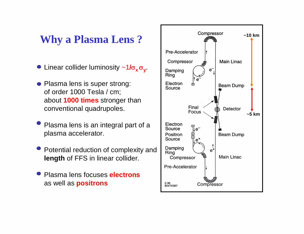
Why a Plasma Lens ? ~10 km
~5 km
Linear collider luminosity ~1/ x y.
Plasma lens is super strong:of order 1000 Tesla / cm;about 1000 times stronger thanconventional quadrupoles.
Plasma lens is an integral part of aplasma accelerator.
Potential reduction of complexity andlength of FFS in linear collider.
Plasma lens focuses electronsas well as positrons

Early ExperimentsANL - J.Rosenzweig,et al.,(1989)
Thick plasma lens 35 cm long with n~1-7 x 1013 cm-3
21 MeV electron beam with n ~ 2.5-4 x 1010 cm-3
Beam size reduced from = 1.4 mm to = 0.9 mm
Tokyo university - H. Nakanishi, et al., (1990)Thin plasma lens with density n~1.4 x 1011 cm-3
18 MeV electron beam with n ~ 1.2 x 1010 cm-3
Theory for thin plasma lens is confirmed
UCLA - G. Hairapetian, et al., (1993)Thin plasma lens with n ~ 4 x 1012 cm-3
LBNL - W. Leemans, et al., (1996)
These experiments confirmed the plasma lens concept,but operated at low energies with electron beams only,
and low plasma densities: ~ 10-6 to that for SLC/NLC

SLAC E150 : Plasma Focusing of Positrons
Study plasma focusing for high-energy,high-density electron and positron particle beamsin the regime relevant to high energy colliders
Better understanding of beam-plasma interactionsand benchmarking of computer codesfor future plasma lens designs
Develop compact, simple and economicalplasma lens designs suitable for high-energycollider applications

SLAC E150 Collaboration
P. Chen, W. Craddock, F.J. Decker, R. C. Field, R. Iverson, F. King,R.E. Kirby, J. S. T. Ng, P. Raimondi,D. WalzStanford Linear Accelerator Center, Stanford University
H.A. Baldis, P. BoltonLawrence Livermore National Laboratory
D. Cline, Y. Fukui, V. KumarUniversity of California, Los Angeles
C. Crawford, R. NobleFermi National Accelerator Laboratory
K. NakajimaKEK-National Laboratory for High Energy Physics
A. OgataHiroshima University
A. WeidemannUniversity of Tennessee

Final Focus Test Beam Facility (FFTB) beam parameters (e- and e+)bunch charge: 1.5 x 10¹⁰ (electrons or positrons) per pulsebeam size: 5-11 m in X, 3-5 m in Ybunch length: 600 mbeam energy: 28.5 GeVnorm. emittance: 5 x 10⁻⁵ m rad in X
0.5 x 10⁻⁵ m rad in Ybeam density: ~7 x 10¹⁶ /cm3
Gas Jetgas: N2 or H2, neutral density ~3 x 10¹⁸ /cm3
nozzle size: 3 mmgas pressure: 250-1000 lb per square inch
Plasma Productionbeam-induced ionization: ~7% efficiencylaser-induced ionization: ~50% efficiencylaser pulse: =1.06 m, E~1J, ~ 10 ns FWHMplasma characterization: optical interferometry
Parameters of the E150 Experiment

The Final FocusTest Beam Line
3D drawing ofthe plasma chamber
Schematic Layoutof the Experiment
FNAL, Hiroshima, KEK, LLNL, SLAC, Tennessee, UCLA

Beam Self-ionization Plasma Focusing
29 GeV electron beams
Transverse beam profile Beam envelope
[J.S.T. Ng et al., PRL 2001]

Laser Ionization Plasma Focusing
29 GeV positron beams
Transverse beam profile Beam envelope
[J.S.T. Ng et al., PRL 2001]

SLAC E157, E162, E164X: Plasma Acceleration and Focusing[P. Muggli, 2003]

E164X: Plasma focusing as a function of plasma density[P. Muggli et al, PRL 2004]

E164X: Halo Formation and Emittance Growth[P. Muggli et al, PRL 2008]
Observed halo formation: e+ beam Use simulation (QuickPIC) toquantify emittance growth.
Mitigate using a hollow channel plasma?

UCLA/FNPL Experiment: Underdense Plasma Focusing[M.C. Thompson et al., PAC 07]
Beam:15 MeV, 19 nC, e- beamPlasma Lens: 20 mm, np ~ 5E12 cm-3
Angular spread from lens aberration:n,x,eff m vs. n,x,0 ~ 87 m
Strong focusing with lower aberrationthan overdense lens.
Collider Application: Detector Background
• The plasma lens is placed deep inside the particledetector near the IP
• Background estimates strongly dependent ondetector configuration and machine parameters
• Simulation studies indicate backgroundpredominantly due to photons

Background Study for NLC-Type Detector[A. Weidemann et al., SLAC-PUB-9207, 2002]
•NLC beam parameters•Plasma lens: overdense np = 2x1018 cm-3, 3mm thick

[SLAC-PUB-9207]

Plasma-induced Detector Background:Further Studies Needed
• Important issue for collider application
• So far only one serious study has beencarried out (some time ago)
• Must include simulation of detector
• What about underdense plasma lens?

Summary and Outlook• Strong plasma focusing of e- and e+ has been
demonstrated for collider parameters; underdenseplasma lens advantageous.
• Further experiments needed to study emittancepreservation/growth mitigation: FACET, NLCTA,…
• Plasma-induced detector background requiresfurther study
Recommended