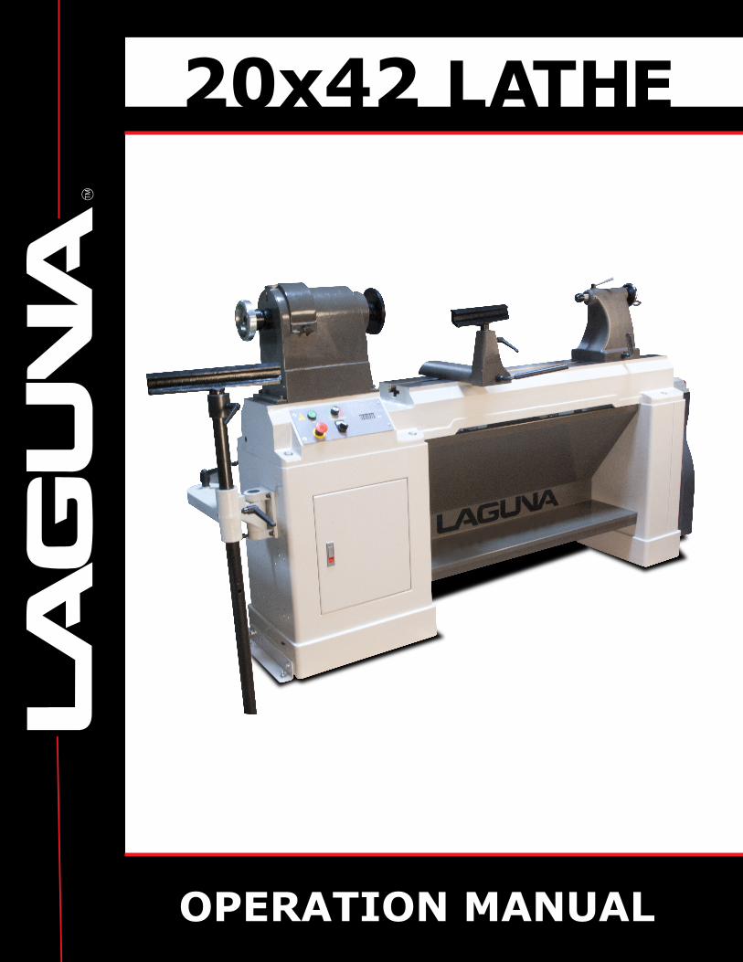
20x42

2
Dear Woodworker:
Thank you for your purchase and welcome to the Laguna Tools group
of discriminating woodworkers. I understand that you have a choice of where to purchase your machines and appreciate the confidence
you have in our products.
Every machine sold by Laguna Tools has been carefully designed and
well thought through from a woodworker’s perspective. I cut on our bandsaws, lathes, table saws and combination machines. Through
my hands-on experience, I work hard to make our machines better.
I strive to give you machines that inspire you to create works of art. Machines that are a joy to run and work on. Machines that
encourage your performance.
Today, we offer high-performance machines with innovative
solutions that meet the needs of woodworkers and their ever-
evolving craft.
I started Laguna Tools as a woodworker, I still am.
Thank you again for becoming a Laguna Tools customer.
Torben Helshoj
President and Founder - Laguna Tools
Imagination, Innovation and Invention at work.

3
Table of contents
Page number
Safety Rules 4
Warranty 5
Noise emission 6
Specification sheet 6
Receiving your machine 6
Introduction to your machine 7
Parts of the machine 7
Where to locate your machine 11
Unpacking your machine 12
Assembly and setup 13
Maintenance and troubleshooting 20
Exploded view drawings 23
Electrical drawing 24

4
Safety Rules. As with all machinery there are certain hazards involved with the operation and use. Using it with caution will considerably lessen the possibility of personal injury. However, if normal safety precautions are overlooked or ignored, personal injury to the operator may result. If you have any questions relative to the installation and operation, do not use the equipment until you have contacted your supplying distributor. Read the following carefully before operating the machine.
1. Keep the working area clean and be sure adequate lighting is available.
2. Do not wear loose clothing, gloves, bracelets, necklaces or ornaments. Wear face, eye, respiratory and body protection devices as indicated for the operation or the environment.
3. Be sure that the power is disconnected from the machine before tools are serviced or an attachment is to be fitted or removed.
4. Never leave the machine with the power on. 5. Do not use dull, gummy or cracked cutting tools. 6. Be sure that the keys and adjusting wrenches have been removed
and all the nuts and bolts are secured.

5
LIMITED WARRANTY
New woodworking machines sold by Laguna Tools carry a one-year warranty effective
from the date of shipping. Laguna Tools guarantees all new machine sold to be free of
manufacturers’ defective workmanship, parts and materials. We will repair or replace,
without charge, any parts determined by Laguna Tools, Inc. to be a manufacturer’s
defect. We require that the defective item/part be returned to Laguna Tools with the
complaint. In the event the item/part is determined to be damaged due to lack of
maintenance, cleaning or misuse/abuse, the customer will be responsible for the cost to
replace the item/part, plus all related shipping charges. This limited warranty does not
apply to natural disasters, acts of terrorism, normal wear and tear, product failure due to
lack of maintenance or cleaning, damage caused by accident, neglect, lack of or
inadequate dust collection, misuse/abuse or damage caused where repair or alterations
have been made or attempted by others.
Laguna Tools, Inc. is not responsible for additional tools or modifications sold or
performed (other than from/by Laguna Tools, Inc.) on any Laguna Tools, Inc.
woodworking machine. Warranty maybe voided upon the addition of such described
tools and/or modifications, determined on a case-by-case basis.
Normal user alignment, adjustment, tuning and machine settings are not covered by this
warranty. It is the responsibility of the user to understand basic woodworking machinery
settings and procedures and to properly maintain the equipment in accordance with the
standards provided by the manufacturer.
Parts, under warranty, are shipped at Laguna Tools, Inc.’s cost either by common carrier,
FEDEX ground service or a similar method. Technical support to install replacement
parts is primarily provided by phone, fax, e-mail or Laguna Tools Customer Support
Website. The labor required to install replacement parts is the responsibility of the user.
Laguna Tools is not responsible for damage or loss caused by a freight company or other
circumstances not in our control. All claims for loss or damaged goods must be notified
to Laguna Tools within twenty-four hours of delivery. Please contact our Customer
Service Department for more information.
Only new machines sold to the original owner are covered by this warranty. For warranty
repair information, call 1-800-332-4094.
Copyright 2010 Laguna Tools, Inc
** Warning – no portion of these materials may be reproduced without written approval
from Laguna Tools, Inc.

6
Noise emission. Notes concerning noise emission : Given that there exists a relationship between noise level and exposure times, it is not precise enough to determine the need for supplementary precautions. The factors affecting the true level of exposure to operators are clearly the amount of time exposed, the characteristics of the working environment, such as other sources of dust and noise, etc. for example, adjacent machines - in other words, the level of ambient noise. It is possible that exposure level limits will vary from country to country. Specification sheet.
Motor 3 HP
Voltage 220V Three phase
Swing over bed 20 inches [508mm]
Distance between centers 43 inches [1092mm]
RPM range 0 to 3000 RMP
Spindle 1-1/4 in. x 8 TPI RH MT number 2
Tail stock Cast iron MT number 2
Tool rest 13 inch
Face plate Yes
Weight 578 lbs.
Length/Width/Height..
103 x 25 x 49-1/2 in
Receiving your machine Note. It is probable that your machine will be delivered by a third party. Before
you unpack your new machine you will need to first inspect the packing, invoice and shipping documents supplied by the driver. Insure that there is no visible damage to the packing or the machine. You need to do this prior to the driver leaving. All damage must be noted on the delivery documents and signed by you and the delivery driver. You must then contact the seller [Laguna Tools] as soon as practical. If damage is found after delivery, contact the seller as soon as is practical. Note. It is probable that you will find sawdust within your machine. This is because the machine has been tested prior to shipment from the factory and or Laguna Tools. Laguna Tools endeavors to test machines prior to shipping to customers as movement can take place during transportation. It must be noted that additional machine movement can take place between Laguna Tools and the end user and some adjustments may have to be undertaken by the customer. These adjustments are covered in the various sections of this manual.

7
Introduction to Lathes. This machine is designed to give you years of safe service. Read this owners manual in its entirety before assembly or use. Parts of the Lathe The lathe consists of a number of major parts, which are discussed in this manual. Take the time to read this section and become familiar with the machine.
Identification.
There is a plate at the back of the machine listing all the manufacturing data, including the serial number, model, etc.
Out board leg
Lathe cabinet
Lathe legs.
The Leg is a heavy pressed steel construction that gives the machine a low centre of gravity, and ensures that it is very stable. The lathe cabinet supports the other end of the bed. There is a metal tray that joins the two parts that is used to store tools and equipment being used on the lathe.
8
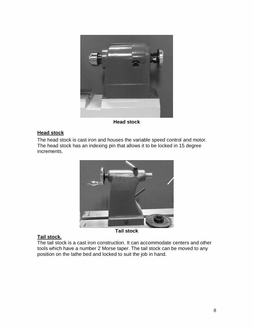
Head stock
Head stock
The head stock is cast iron and houses the variable speed control and motor. The head stock has an indexing pin that allows it to be locked in 15 degree increments.
Tail stock
Tail stock.
The tail stock is a cast iron construction. It can accommodate centers and other tools which have a number 2 Morse taper. The tail stock can be moved to any position on the lathe bed and locked to suit the job in hand.

9
Bed tool rest
Outboard tool rest
Tool rest
There are two tool rests. One that is located on the bed of the lathe and the second tool rest that is located at the left hand of the lathe. The left hand tool rest is used for bowl turning and is adjustable both vertically and also laterally to suite the job in hand.
Door switch Motor electronics
Motor

10
Speed sensor
Electrical cable
Electrical system.
The electrical control system is housed inside the left hand leg and accessed by opening the door located at the front of the lathe. There is a speed sensor that is located inside the pulley housing and is accessed by lifting the pulley cover. A power cord is provided. The power cord [located at the back of the lathe] is not provided with a plug as this will depend on your insterlation.
Lathe bed viewed from the under side
Bed of the lathe. The bed of the lathe is a heavy cast iron construction and is ribbed for extra rigidity.

11
Tool tray
Tool tray.
There is a large tool tray located under the bed of the lathe that is convenient for storing tools and equipment that is used on the lathe. What you will receive with the Lathe.
Tools Knock out rod
Running centre Drive centre
Face plate
Where to locate your machine.
Before you remove your machine from the packaging, select the area where you will use your machine. There are no hard and fast rules for its location, but below are a few guidelines: 1. There should be an area at the front of the machine suitable for comfortable
working. 2. There should be sufficient area at the back of the machine to allow access for
adjustments and maintenance to be conducted. 3. Adequate lighting. The better the lighting the more accurately and safely you
will be able to work. 4. Solid floor. You should select a solid flat floor, preferably concrete or
something similar. 5. Locate it close to a power source and dust collection. 6. Allow an area for the storage of blanks, finished products and tools.

12
Unpacking your machine.
To unpack your lathe you will need a screwdriver, tin snips and a wench. 1. Using the tin snips, cut the banding that is securing the packing box [If fitted]. WARNING: EXTREME CAUTION MUST BE USED, BECAUSE THE BANDING WILL SPRING AND COULD CAUSE INJURY. 2. Dismantle the box, including the sides as this will ease access to the machine.
Mounting bolts
3. Remove the base mounting bolts that secure the machine to the base of the
box. 4. It is recommended that the lathe be removed from the packaging by lifting it
with a hoist or forklift using a "SLING". Remove the packaging and lower to the floor. Insert the slings only under the bed of the lathe and as far apart as possible. Do not lift the lathe by slinging under the tool tray. Note. The machine is heavy. Ensure that you have sufficient people. Note. If you have any doubt about the described procedure, seek professional assistance. Do not attempt any procedure that you feel is unsafe, or that you do not have the physical capability of achieving.

13
Assembly and setup
The machine comes mostly assembled. You will have to assemble the tool rest to the bed of the machine.
Mounting the late to the floor
Floor mounting bracket
Two floor mounting brackets are provided to attach the lathe to the floor [optional]. Floor mounting hardware is not provided. The mounting brackets will accept 3/8” fixings. If you decide to mount the lathe to the floor you may have to shim the lathe to ensure that the bed is level in both directions. Assembling the tool rest the bed of the machine.
Tool rest clamp nut
Tool rest
Lathe bed tool rest.
Remove the clamping nut and washer. Fit the tool rest onto the bed of the lathe. Refit the washer and nut. Adjust the nut until the clamping handle secures the tool rest to the bed of the lathe. The tool rest can be moved to any position on the bed of the lathe, and also in-out to suit the job in hand. To move the tool rest, loosen the locking handle, move to the required position and lock.
14
Positioning Inboard Tool Rest on lathe bed. Loosen the tool rest holder lock lever and move the tool rest assembly to the desired position. Once in the desired position lock the lever to secure the tool rest assembly in position. Note: The tool rest holder lock has an adjusting nut that may need adjustment with time. Adjusting Tool Rest Height.
Loosen the tool rest lock handle and adjust the angle or height of the tool rest. Position the tool rest approximately 1⁄4" away from the work piece and Approximately 1⁄8" above the work piece center line. Re-tighten the tool rest lock handle to secure the tool rest in position. Turning jobs larger than 20" in diameter, mount the work piece on the outboard side of the lathe and use the outboard tool rest. To use the outboard tool rest.
Holding the tool rest support rod firmly, loosen the lock levers and move the tool rest to the required position. Re tighten all lock levers before starting the operation. Connecting the electrical supply. Ensure that the electrical supply corresponds with that of the machine [Single phase 110V]. It is recommended that you use a 15-amp main breaker. Amp draw under full load
9 Amps
Note. A qualified electrician must carry out the installation.
Cleaning the machine.
Remove the rust protection grease with WD 40 or a similar solvent. It is important that you remove all the grease and re lubricate with a Teflon-based lubricant. Teflon has fewer tendencies to attract sawdust, and cause clogging. On flat surfaces it is recommended that the grease is scraped off the machine with a plastic scraper [do not use a metal scraper, as this could damage the machine surfaces].This will save time and reduce that amount of solvent that is required to clean the lathe.

15
Knock out rod fits through hole in the
back of the handle
Knock out rod
Rotating centre
Fitting the rotating centre. Ensure that the bore of the tail stock is clean. The rotating centre has a number No 2 Morse taper that fits into the tail stock. Push the centre into the tail stock bore firmly, and ensure that it is securely located. To remove the centre, push the knock out shaft through the hole in the back of the tail stock and give it a sharp knock. This will remove the rotating centre. Ensure that the centre does not drop. It is suggested that you hold your hand under the centre to catch it as it is hit with the knock out rod. Note. Do not leave the removal shaft in the tail stock with the machine running. Fitting the drive centre in the head stock. Ensure that the bore of the head stock is clean. The drive centre has a number No 2 Morse taper that fits into the head stock. Push the centre into the head stock bore firmly, and ensure that it is securely located. To remove the centre, push the removal shaft into the back of the head stock, and give it a sharp knock. This will remove the drive centre. Ensure that the centre does not drop. It is suggested that you hold your hand under the centre to catch it as it is hit with the knock out rod. Note. Do not leave the removal shaft in the head stock with the machine running.

16
Spindle lock engaged
Spindle lock disengaged
Fitting the face plate and or removing the hand wheel. Lock the spindle in position. The face plate screws onto the spindle and is locked in position with the Allen screws. Remove the spindle lock before you start the lathe. To removal the face plate, lock the spindle, loosen the Allen screws, and rotate the face plate. Remember to remove the spindle lock before you start the lathe
The faceplate can also be mounted on the outboard side of the lathe for turning work pieces larger than 20" in diameter. In this case, the hand wheel is mounted on the inboard side of the lathe.
On button Speed control button Speed display
Stop button Forward / reverse switch
Head stock controls and adjusting the spindle speeds. On switch powers the system and starts the spindle rotating to the speed set by
the variable speed control knob. It is suggested that the variable speed control knob is set to the approximate speed prior to starting the spindle rotation and then once the spindle is rotating fine tune the spindle speed. With the drive belt on the low range the spindle speed is from 10 to 1000 rpm. With the drive belt on the mid range the spindle speed is from 1000 to 2000 rpm. With the drive belt in the high range the spindle speed is from 2000 to 3000 rpm. Red off switch removes power from the system.
17
Once the red off switch has been pushed, it has to be twisted, and pulled out to reset the power. If the lathe will not start, check that the red stop switch is in the fully out position. Note: Always disconnect the machine from the power when conducting
maintenance or adjustments to the lathe, [changing the belts on the pulleys, etc]. Forward / reverse switch changes the direction of the spindle. Never change
the position of the switch while the spindle is rotating. If the spindle rotation is changed while the spindle is turning the electronics and or the motor will be damaged. The forward / reverse switch must not to be used as a quick stop for the lathe spindle. Test run.
Now that the assembly is complete and you have a good understanding of the lathe controls, it is time to conduct a test run to check that all the functions of the lathe are working correctly. Check that the spindle lock is disengaged. Check that all tools etc have been removed from the lathe. Make sure that you have read and understood the manual. Press the red stop button and then twist anti clockwise so that it pops out. Turn the speed dial to zero [off position]. Check that the cabinet door is fully closed. Connect the power to the lathe. The test will check that the motor works correctly, all the controls function correctly and that the safety switches function correctly. If any of the tests fail, the lathe must not be used until the fault has been corrected. Press the on button and using the speed dial increase the speed of the spindle slowly. The lathe should run smoothly with little or no vibration. Reduce the speed using the speed control dial until it is in the off position. Turn the speed control dial until full speed is achieved and then press the red stop button. The lathe should stop. Press the start button. The lathe should not start. This is a safety feature and must function correctly. If it fails to function the lathe must not be used until the fault has been corrected. Turn the speed dial to the off position and reset the stop button by turning anti clock wise until it pops out. Press the start button and turn the speed dial until the spindle is turning. Open the cabinet door a small amount until the door safety switch functions. With the door slightly open the spindle should have the power removed and the spindle should stop turning. This is a safety feature and must function correctly. If it fails to function the lathe must not be used until the fault has been corrected.

18
Upper pulleys
Ratchet clamp handle
Adjustment lever
Changing the drive belt to different pulley sets. Remove the power from the lathe.
The motor and pulleys are accessed through the cabinet door. Loosen the ratchet clamp handle and move the adjustment lever to remove the tension on the drive belt. Re clamp the ratchet clamp lever. Move the drive belt to the required set of pulleys. Loosen the ratchet clamp handle, re apply tension to the drive belt with the adjustment lever and re clamp the ratchet clamp handle. The tension should be about 1/8” movement of the belt when pressed with moderate thumb pressure. Before reconnecting the power to the lathe, ensure that the upper pulley cover is closed and locked in position. There is a micro switch that acts on the lower door and removes power from the lathe. [Never rely on the switch and disconnect the lathe from the power prior to changing the drive belts to a different set of pulleys]. If the door is not fully closed the lathe will not start. Prior to starting the lathe, check that the door is fully closed.

19
Spindle lock Tail stock position lock
Tail stock The tail stock can be moved to any position on the bed of the lathe. To move the tail stock, unlock the tail stock position locking handle, slide the tail stock to the required position and lock. The tail stock spindle can be extended and retracted by rotating the handle located at the back of the tail stock. The spindle can be locked in position with the locking handle on top of the tail stock. Always lock the spindle when operating the lathe.
Viewing hole
Spindle lock disengaged
Spindle lock engaged
Spindle lock / indexing.
The spindle lock engages in any one of 24 holes. This allows for the spindle to be locked in 15 degree. Never start the lathe with the spindle lock engaged as this will strain the motor and the lathe electronics. Each spindle lock hole has its own number that is viewed through the viewing hole on the out board side of the head stock.

20
Maintenance
General. Keep your machine clean. At the end of each day, clean the machine. Wood contains moisture, and if sawdust or wood chips are not removed they will cause rust. In general, we recommend that you only use a Teflon based lubricant on the lathe. Regular oil attracts dust and dirt. Teflon lubricant tends to dry and has fewer tendencies to accumulate dirt and saw dust. Periodically check that all nuts and bolts are tight. Drive belt
The drive belt should last for many years [depending on the usage] but need to be inspected regularly for cracks, cuts and general wear. If damage is found, replace the belt. Bearings. All bearings are sealed for life and do not require any maintenance. If a bearing becomes faulty, replace it. Rust The lathe is made from steel and cast iron. All none painted surfaces will rust if not protected. It is recommended that they are protected by applying wax or a Teflon based lubricant General.
Each week the motor should be cleaned of any accumliated saw dust as this will reduce the motor cooling. Also check that the cabinet cooling slots are clean and free from a build up of sawdust and dirt. Check all nuts and bolts are tight and that there is no dammaged parts Troubleshooting.
Symptom Possible cause Possible sloution
Lathe will not start.
Check that the stop switch is in out positon.
Reset stop switch.
Check that the electrical power cord is plugged into the power outlet.
Plug in the lathe to the power.
Check that the electrical supply is on.
Reset the breaker.
With the power disconnected Rewire plug.

21
from the machine, check the wiring to the plug is correct.
Check that the rubber insulation is stripped enough and is not causing a bad connection.
Strip back wiring.
Check that all the screws are tight.
Tighten screws.
Start switch faulty. Replace switch.
Spindle direction switch faulty. Replace switch.
Inverter faulty. Replaceinverter.
The machine will not stop.
This is a very rare occurrence as the machine is designed to fail-safe. If it should occur and you cannot fix the fault, seek professional assistance. The machine must be disconnected from the power and never run until the fault has been rectified.
Stop switch faulty. Replace the stop switch.
Motor tries to start but will not turn.
With the power disconnected from the machine. Try to turn the spindle by hand. If the spindle will not turn, check the reason for the jamming.
Remove cause of jamming.
Capacitor faulty.
Replace the capacitor.
Motor faulty. Replace the motor.
Motor overheats. The motor is designed to run hot, but should it overheat it has an internal thermal overload protector that will shut it down until the motor has cooled, and then it will reset automatically. If the motor overheats, wait until it has cooled and restart.
If the motor shuts down consistently check for the reason.
Typical reasons are dull cutting tools, motor cooling fan clogged or faulty, motor cooling fins clogged, over feeding the job, and excessive

22
ambient temperature.
Squeaking noise. Check that the motor cooling fan is not contacting the fan cover.
Adjust mootor cooling fan.
Check the bearings. Replace bearings.
Check the drive belt. Retension or replace drive belt.
Spindle slows down during a cut. .
Dull cutting tools. Replace the tool or have it re-sharpened.
Feeding the wood too fast. Slow down the feed rate.
Oil or dirt on the drive belt.
Clean or replace the drive belt.
Machine vibrates.
Machine not level on the floor. Re-level the machine ensuring that it has no movement.
Damaged drive belt. Replace the belt.
Job is not balanced. Change to slower speed and or balance the job
Damaged pulley. Replace the pulley.
Motor loose. Tighten motor.
Lathe not mounted on the floor correctly and is not sitting on four corner points.
Mount lathe correctly.
Bearing faulty. Replace bearings.
Motor mounting loose or broken.
Tighten motor and or replace broken part.
Loose or dammaged cover. Tighten and or replace cover.
Loose pulley. Tighten pulley.
Job mounted incorrectly. Remount job.
Spindle speed too fast for job. Slow the lathe down to correct speed.
Dull or incorrect tools being used.
Use correct /sharp tools.
Tail stock moves. Tail stcck clamp is not adjusted correctly.
Adjust tail stock clamping nut.
Bed is greassy. Clean bed.
23
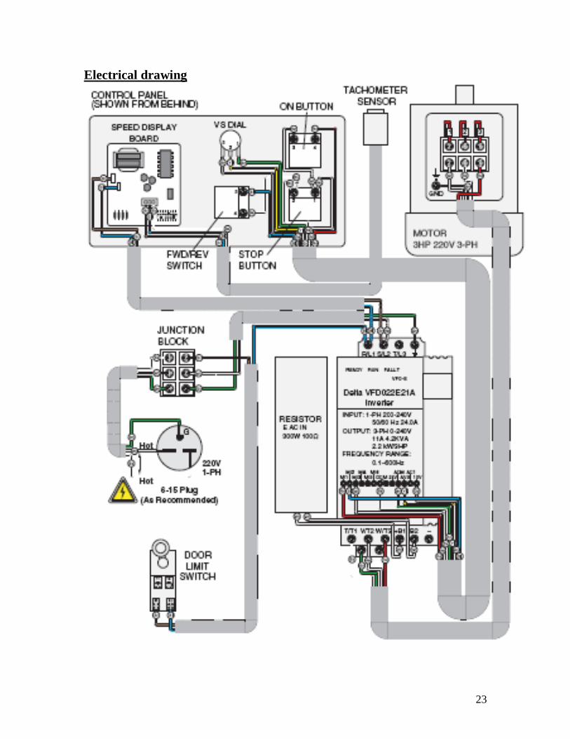
Electrical drawing
24

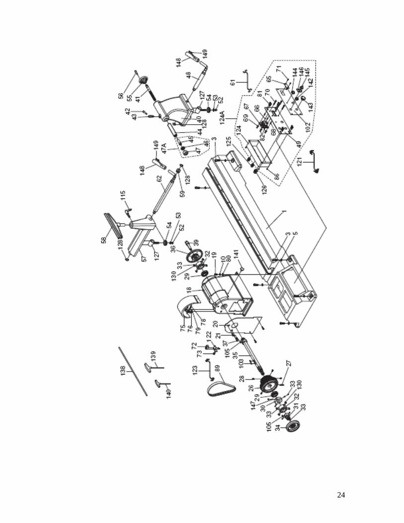
25
Part
No DESCRIPTION
PART
No DESCRIPTION
1 BED 66 SPACING COLLAR
3 HEX BOLT 7/16-14 X 1-1/2 67 TRANSFORMER
5 LOCK WASHER 12MM 68 SPACER
10 LOCK WASHER 5/16 69 FIBER WASHER 12MM
18 HEAD STOCK 70 FLAT HD SCR 5-40 X 1
19 HEX BOLT 5/16-18 X 1-1/4 71 FLAT HD SCR 5-40 X 3/4
20 BELT WHEEL COVER 72 TACH SENSOR BAKS DA-1805NO
21 PHLP HD SCR 10-24 X 5/16 73 PHLP HD SCR M3-.5 X 20
26 PULLEY 3-STEP J9 SHEAVES 75 UPPER COVER
27 SET SCREW M8-1.25 X 40 76 HINGE ASSEMBLY W/O SCREWS
28 PHLP HD SCR M6-1 X 16 78 FLAT HD SCR 10-24 X 5/16
29 TAPERED BEARING LM67048/10 79 FLAT HD SCR 10-24 X 1/4
30 LOCK COLLAR 80 FLAT WASHER 5/16
31 SPINDLE ADAPTER 81 FLAT HD SCR 10-24 X 5/8
32 SHAFT JOINT 82 HEX NUT 5-40
33 SET SCREW 1/4-20 X 1/4 86 HEX NUT 10-24
34 SPINDLE HANDWHEEL 89 RIBBED V-BELT 580J9
35 SPINDLE 102 FACEPLATE LABEL
36 FACE PLATE 1-1/4 X 8 TPI 103 KEY 8 X 7 X 50
37 LOCK SET 105 KEY 5 X 5 X 18
39 SPUR CENTER 115 ADJUST HANDLE M12-1.75 X 20
40 TAILSTOCK BASE 121 CTRL PANEL CORD 8 WIRE 18AWG
41 TAILSTOCK LEADSCREW 122 TACH SENSOR BRACKET
42 SHORT HANDLE 123 TACH SENSOR CORD 3W 24AWG
43 CAM SPINDLE 124 SWITCH BOX
44 TAILSTOCK QUILL 124A COMPLETE SWITCH BOX ASSY
45 LIVE CENTER SHAFT 125 LT STRAIN RELIEF PG11
46 BALL BEARING 6002ZZ 126 LT STRAIN RELIEF PG13.5
47 LIVE CENTER HEAD 127 RING SHAFT
47A LIVE CENTER ASSY 128 EXT RETAINING RING 19MM
48 TAILSTOCK LOCK SHAFT 130 SET SCREW 5/16-18 X 5/16
49 CONTROL PANEL FACEPLATE 138 PUSH ROD 8 X 600MM
52 LOCK NUT M12-1.75 139 T-WRENCH 4MM X 100L
53 FLAT WASHER 1/2 140 T-WRENCH 3MM X 100L
54 SLIDE PLATE 141 THUMB SCREW 1/4-20 X 5/8
55 HANDWHEEL 142 GO BUTTON (GREEN)
56 HANDWHEEL HANDLE 143 STOP BUTTON (RED)
57 TOOL REST BASE 144 SPEED DIAL
58 TOOL REST 145 FWD/REV KNOB
59 TUBE 146 FWD/REV PLATE
61 DIGITAL DISPLAY CORD 2W 18AWG 147 COPPER SLUG 5 X 8MM
62 TOOL REST LOCK SHAFT 148 LOCK SHAFT EXTENSION
65 ACRYLIC BOARD 149 SET SCREW M5-.8 X 5

26

27
Part No DESCRIPTION PART No DESCRIPTION
2 LEFT STAND (CABINET) 94 CAP SCREW M8-1.25 X 15
5 LOCK WASHER 12MM 95 CAP SCREW M8-1.25 X 25
6 LOCK WASHER 12MM 96 LOCK WASHER 3/8
8 HEX BOLT 7/16-14 X 1-1/4 97 FLAT WASHER 3/8
9 L-BRACKET 98
INVERTER PWR CORD 2W
14AWG
10 LOCK WASHER 5/16 104 KEY 8 X 7 X 90
11 DOOR 106 OUTBOARD MOUNTING BRACKET
12 STAND ACCESS HANDLE 107 OUTBOARD ARBOR SHAFT
13 RUBBER FOOT 108 LOWER BRACKET
14 HEX BOLT 5/16-18 X 5/8 109 UPPER BRACKET
15 PARTITION BOARD 110 ARBOR SHAFT TUBE
17 RIGHT STAND 111 OUTBOARD LONG SHAFT
22 MOTOR 112
OUTBOARD SHORT
SHAFT
23 MOTOR PULLEY 113
ADJUST HANDLE M10-1.5
X 20
24 SET SCREW M8-1.25 X 8 114 ADJUST HANDLE M12-1.5 X 60
25 SET SCREW M8-1.25 X 30 115 ADJUST HANDLE M12-1.75 X 20
50 CAP SCREW 10-24 X 1/2 116
ADJUST HANDLE M12-1.75
X 25
58 TOOL REST 117 HEX BOLT M8-1.25 X 30
60 L-BRACKET 118 FLAT WASHER 8MM
64 LIMIT SWITCH CORD 2W 18AWG 119 LOCK NUT M8-1.25
77 HEX NUT 5/16-18 120 SET SCREW M8-1.25 X 10
80 FLAT WASHER 5/16 125 LT STRAIN RELIEF PG11
83 RESISTOR EACIN 300W 100 OHMS 126 LT STRAIN RELIEF PG13.5
84 INVERTER DELTA VFD-E 022E21A 129 RUBBER HANDLE COVER
85 PHLP HD SCR 10-24 X 3/4 131
LMT SWITCH SHINOZAKI
AZD-1004
86 HEX NUT 10-24 132 LIMIT SWITCH BRACKET
87
POWER CORD 3 WIRE
14AWG 133 PHLP HD SCR M4-.7 X 35
88 MOTOR CORD 4 WIRE 14AWG 134
TERMINAL 3-POST (W/COVER)
90 MOTOR BRACKET 135 PHLP HD SCR 10-24 X 1
91 MOTOR MOUNT PLATE 136 FLAT WASHER #10
92 BELT TENSION HANDLE 137 LOCK WASHER #10
93
FLAT HD CAP SCR M8-
1.25 X 20

28
Recommended