MTH HOBBY PRODUCTS INDUSTRIAL CO., LTD.www.mth.com.tw [email protected]
MTH HOBBY 2014
SPECIFICATIONS WING SPAN :1720mmLENGTH:1095mm
2WING AREA:42dmWEIGHT:2300-2600g RADIO:4 CHANNELS ENGINE: .46(2C) .56(4C)
WarningAn RC aircraft is not a toy! If misused, it can cause serious bodilyharm and damage to property. Fly only in open areas, following allinstructions included with your radio.Before beginning the assembly, remove each part from its bag forinspection. Closely inspect the fuselage, wing panels, rudder andstabilizer for damage. If you find any damaged or missing parts,contact the place of purchase.
INS
TR
UC
TIO
N M
AN
UA
LIN
ST
RU
CT
ION
MA
NU
AL
No.867
PIPER J-3Cub
GP/EP

1
Contents of Kit/Parts Layout
Tools and suppliers needed (not included in kit):Phillips screws driver #0/#1 / Curved scissorsHex wrench 1.5/2mm/2.5mm/6mm / Hobby knife / Ruler / Iron / Cross wrenchPliers / Z-bender / Sanding paper / Epoxy 5-10 minutes / Marker / CA glue UHU foam glue / Superglue / Cross wrench / Reamer / Solder IronThread lock / Side Cutter / Driller 2mm/6mm / Transparent Tape / Pin3M fiber tape
Hobby knifeReamerSanding paperIronRulerMarker
2
Recommended radio and equipment (not included in kit):4 channels radio x 1 pieceReceiver x 1 piece45g servo x 4 pieces 30cm extension x 1 piecesSwitch x 1 pieceEngine: 46(2C)c~56(4C)Aluminum spinner (for Gas engine)4.8V battery
Contents of Kit / Parts Layout
For EP:Motor: 500~680KVBattery: 2200~3000mAh 4-cell Li-PoESC: 50-60APropeller: 11x6" ~12x6"Aluminum spinner (for EP flying)
Place the main wing and hinges onthe working table.
Bend the hinges several times.Spread the Super glue on the hingesand insert into the hinges slot on themain wing and aileron. Apply thetape to hole the aileron in positiontemporary until the glue dry enough.
Try to fit the wing joiner into the mainwing. If too tight, use sand paper totrim the wing joiner. When satisfy theassembly, use pencil to mark thelocation of the servo try.
Mix 10-min epoxy and spreadgenerous amount of epoxy on thewing joiner. Fit the wing joiner intothe main wing. Apply tape on theconjunction temporary until theepoxy dry enough.
Take the main wing front planking out of the wooden hardware bag. Spreadepoxy on the planking and secure onthe main wing.
Place the main wing servo tray on theworking table. Use epoxy to securetwo sides of planking on the tray.

3 4
Place the servo tray on the center ofthe main wing set. Use marker to mark the location of the servo tray onthe main wing.
Use hobby knife to remove thecovering over the hole.
Use epoxy to secure the servo tray inposition.
Place the servo on the servo tray andsecure it in place with the screws come with the servo.
Take two pieces of 330mm rods outof the hardware bag. Use side cutterto cut all the parts out of the plasticparts tree. Screw a clevis onto thethreaded end of each rod. Thread theaileron horns onto the aileron torquerods in the wing until the rod is flushwith the aileron horn. Attach theclevises onto their respective aileronhorns. Center the aileron servo andusing marker to place a mark on theunthreaded end of the aileronpushrods where they pass theirrespective servo arm.
Using z-bend pliers, make a z-bend at the marked location on each rodand cut off the excess rod.
Use 2mm reamer to enlarge the holeon the servo arm. Place a piece offuel tubing over the clevises.This will provide extra insuranceagainst the clevises accidentallycoming open. Install the z-end intothe hole of the servo arm. Adjust theaileron torque rod length by screwingin or out until the aileron is exactly inthe neutral position when the servo iscentered and clevis is in the aileronhorn. Adjust both sides.
Find the pre-serving opening on bothsides of the fuselage for assemblingwindows. Use hobby knife to removethe covering over the openings.Please reserve 6mm covering on theedges of the openings.
OUse iron (140 C) to trim the edgesand use hobby knife to remove theexcess covering.
Place the window set on the workingtable and use curved scissors toremove window from the window set.Please reserve 6mm on the edges. Spread UHU glue along the edges of

65
Place the yellowing covering andmain gear planking on the workingtable. Iron on the covering onto themain gear planking.
Iron on the covering onto the wingstruts and the triangle reinforcingplanking.
Iron on the covering onto the frontedge of the main wing.
Place the black covering, decorativemuffler and spring on the workingtable. Iron on the black covering ontothe muffler and spring. Please notethere is a hole on the center part ofthe spring. Use reamer to re-openthe hole after ironing.
Find a long trip of yellow covering inthe hardware bag. Iron on theyellowing covering onto theconjunctions.
Try to fit two struts together and usehobby to remove the covering on theconjunctions.
Use epoxy to glue the struts togetherand use tape to secure the strutstemporary.
Spread generous super glue on thehinges and insert the hinges into therudder until the hinge line is even withthe leading edge of the rudder. Placethe rudder onto the vertical stabilizer.
Place the horizontal stabilizer on theworking table. Use ruler to mark thecenter line on the stabilizer. Place thefuselage on the stabilizer. The centerline of the fuselage must meet thecenter line on the stabilizer. Use 3
pieces of needle to fix the stabilizeron the fuselage.
Use a pencil to carefully trace aroundthe bottom and the top of thestabilizer where it meets the fuselage.Remove the fuselage.
Use a straight ruler to mark the areainside the line.
Using a hobby knife carefully cutaway the covering inside the linesmarked above. Be carefully not to cutinto the wood as doing so will weakenthe structure.
window set and secure on thefuselage. Apply tape on the windowset for holding it in place until theglue is dry enough.
13
0 m
m
60.2 mm
12 mm
O18.5

7 8
Spread generous super glue on thehinges and insert the hinges into theelevator. Place the elevator onto thehorizontal stabilizer.
Take 6mm dowels out of thehardware bag. Use sand paper tosand both ends for making 1mm 45degree angle.
Place the main wing onto thefuselage and secure in place with4x40mm screws and washers. Use6mm driller to open the hole on theplanking, depth is around 15mm.
Spread some epoxy on half of thedowel and insert into the main wing.
Place the tail wheel and 2mm collaronto the tail gear and secure with3x5mm screw.
Use ruler to mark a position on therudder. It is 35 mm from the bottom.
Use a sharp hobby knife to open a Vslot (depth: 2mm) on the markedposition.
Use 2mm driller to drill a hole on themarked location for accepting the tailwheel guide wire.
Spread some epoxy into the hole forsecuring the tail wheel guide wireinside the rudder.
Use hobby knife to remove thecovering on the bottom of the vertical.
Apply some epoxy the vertical andhorizontal where they come incontact with the fuselage. Assemblethe vertical and horizontal on the
There is a gap between vertical andhorizontal on both sides. Try to fit thetriangle reinforcement into the gap.Please note it must fit perfect. If not,use sand paper to trim the edges ofthe reinforcement. When satisfy thelocation, use pencil to mark theoutline on the vertical and horizontal.

9 10
Use 2.6x 10mm tapping screw tosecure the tail wheel assembly inlocation.
Take dowels, clevis and heat shrinktubing out of the hardware bag. Takea rod of 5mm. Use plier to make a90 degree bend on no threaded end.Insert the 90 degree bend into the
Hole of the wood dowel. Slide a pieceof heat shrink tubing over each endof the wood dowel and shrink it inplace using a heat gun.
Carefully cut away the covering onthe top left side of the fuselage nextto the vertical fin for the rudder andthe right side for the elevator this iswhere the pushrods will exit. Positionthe assembled pushrods through thefuselage to the exit. Slide a piece offuel tubing and screw the clevis onthe end of the pushrod.
Install the control horns on theelevator an rudder. When installingthe control horns, it is important thatthe holes in the control horns, wherethe pushrod attaches are directly in-line with the control surface hingeline. Use 2mm driller drill hole.Secure the control horns and plate inplace with 2 x 15mm screws.
Using Z-bend pliers, make a Z-bendat the marked spot on the rod. Use2mm driller to open a hole on theservo arm. Insert Z-bend into servoarm and secure with screw. Slide thefuel tubing to the clevis.
Take the motor mount planking out of
Find two planking that has the sameshape. Use epoxy to glue themtogether. Use ruler to mark a crosson the planking.
Assemble the planking into the motormount. Use epoxy to secure theplanking in place.
Try to fit the motor on the motormount. Secure the motor cross plate(come with the motor) on the motorplanking with the screws come with
Using a 90 degree triangle, makesure that fin is perpendicular to thehorizontal stabilizer.
fuselage. Use needle or tape to holdthe vertical in place until it'scompletely dry.
O90
Install the servos on the servo trayand secure with the screws whichare included with the servo. Securethe servo tray with epoxy. Center theservo. Using marker to mark the rodwhere it passes the respective servoarm.
160
165
165 150
150
the hardware bag and place on theworking table.

11 12
Use epoxy to secure the motor mount on the fire wall.
Secure the motor assembly on themotor mount with 3x10mm tappingscrews.
Take the eyelets and wire out of thehardware bag. Use nipple pliers tocut the following sizes of wires:220mm x 2 pieces for installing thedecorative spring on the main gear.
205mm x 2 pieces for installing onthe top of horizontal.180mm x 2 pieces for installing onthe bottom of horizontal. Insert the end of the wire into theconjunction of eyelet. Use nipple plierto clamp down the conjunction. Dropsome instant glue on the conjunction.
Try to locate the wire assembly onthe top of horizontal. One end is9.5mm from the top of the vertical.The other end is 5mm from the readedge of the horizontal. Please pullthe wire straight and use screw andwasher to fix it in place temporarily.Don't screw too tight.
Screw one end of 180mm wire to thebottom of the horizontal and theother end to the tail gear.
Check all the wires. They must bebilateral symmetry. Screw the screwsand washers tight to secure the wiresin place.
Use curve scissors to trim the canopy according the molding line.
Try to fit the canopy on the fuselage.Use marker to mark the positionaround 7-8mm from the bottom ofthe canopy. Use reamer to drill a5mm hole. Repeat the sameprocedure on the other side ofcanopy.
Insert the black rubber ring into thecanopy. Please note the canopymust fit into the slot around therubber ring. It will be easier if dropsome water on the ring.
Insert the black rubber ring into theeye screw. Drop some instant screwon the conjunction.
Find a location on the side fuselage.It's 48mm from the gear slot and8mm from the bottom of the fuselage.Use 1.5mm driller to drill a hole onthis location. Screw in the eye screw.
motor. The length of the motorassembly can be adjusted byincreasing or decreasing the woodenspacers.

13 14
Insert one piece of hook-and-loopstrap through the battery tray. Applyone side of Velcro (peel and stickadhesive) on the battery tray.
Apply another side of Velcro on thebattery. Place the battery on thebattery tray and secure in place withhook-and-loop strap.
Place the canopy on the fuselage.Apply a piece of tape to fix it in placetemporarily. When satisfy thelocation, use a marker to make amark on the center of the rubber ring.
Remove the canopy. Use 2mm drillerto drill hole on the marked position.
Take M2x15mm screws, washers andnuts out of the hardware bag. Insert awasher to the screw. Place the screwinside the fuselage and insert throughthe fuselage and canopy. Use washerand nut to secure it in place. Pressthe rubber ring onto the end. It'sconvenient for removing the canopyand changing the battery.
Find the pre-served gear slot on thebottom of fuselage. Use hobby knifeto remove the covering on the slot.
Take one piece of heat shrink tubingout of the hardware bag. Cut thetubing into 5mm x 8 pieces. Pleaserefer to the drawing and note thelocation for placing the tubing. Afterheating the first tubing, move thesecond tubing to over the first tubingand heating again. You can uselighter, heat gun to heating the shrinktube.
Assemble the wheels on the maingears and secure with 4mm collar andM3x5 screws.
Use sharp hobby knife to remove theplanking on the cooling hole.
Try to fit the main gears into the gearslot and secure with gear plate and2.6 x 10mm tapping screws.
Try to fit the decorative planking onthe main gear. Place a saddle cableclip on the main gear where has heatshrink tubing. Use 2.6 x 8mm tappingscrew to secure the planking on thegear.
Secure two hinges on the read edgeof the gear planking with 2x5mmtapping screws.
35 m
m35 m
m
The other side of tape must be pressdown to fuselage.

Apply one piece of 30mm 3M fibertape on the front edge of canopy.
15 16
Use hobby to remove the coveringover the vent.
Assemble the motor with propellerand aluminum spinner. Please notethere is 1.5mm space betweenaluminum spinner and cowling. Tryto fit the cowling on the fuselage.When satisfy the location, apply apiece of tape to hole the cowling inplace. Use 1.5mm driller to drill holefor fixing the cowling on fuselage.Use 2x8mm tapping screws to
Sprinting black on the decorativeplastic engine.
Paint silver on the top of plasticengine.
Use curve scissors to trim the edges.Sand the bottom side.
Spread epoxy to secure the plasticengine on two sides of cowling. (It'sonly one side for GP version.)
Place the main wing on the fuselage.Screw in the M4x40mm wing bolts.
Cut the hinges into two halves. Placeone halve on the wing struts. Markthe position for fixing the hinges onthe struts. Drill 1.5mm hole on themarked position.
Use 2x5mm tapping screws tosecure the hinges on the struts.
Place the wing struts to the fuselage.Please refer to the picture. The eyescrew must be fitted into the slot andfixed with R pin.
secure the cowling in palce.
Please refer to the drawing and findthe blocks inside the main wing forfixing the struts. Place the struts onthe main wing and mark the positionfor hinges. Drill 1.5mm holes on themarked positions.
15
80
17 18
Install the propeller and secure the aluminum spinner.
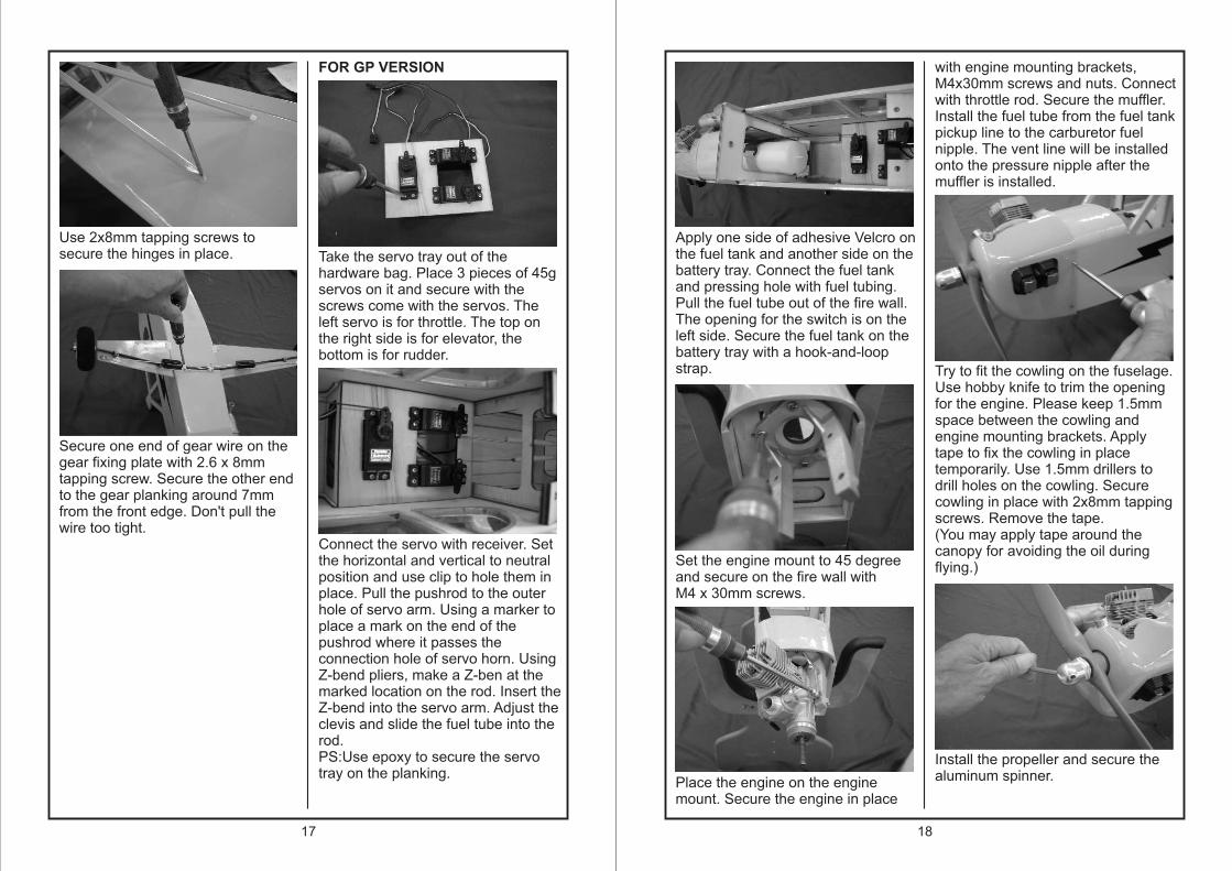
Use 2x8mm tapping screws tosecure the hinges in place.
Secure one end of gear wire on thegear fixing plate with 2.6 x 8mmtapping screw. Secure the other endto the gear planking around 7mmfrom the front edge. Don't pull thewire too tight.
FOR GP VERSION
Take the servo tray out of thehardware bag. Place 3 pieces of 45gservos on it and secure with thescrews come with the servos. Theleft servo is for throttle. The top onthe right side is for elevator, thebottom is for rudder.
Connect the servo with receiver. Setthe horizontal and vertical to neutralposition and use clip to hole them inplace. Pull the pushrod to the outerhole of servo arm. Using a marker toplace a mark on the end of thepushrod where it passes theconnection hole of servo horn. UsingZ-bend pliers, make a Z-ben at themarked location on the rod. Insert theZ-bend into the servo arm. Adjust theclevis and slide the fuel tube into therod.PS:Use epoxy to secure the servotray on the planking.
Apply one side of adhesive Velcro onthe fuel tank and another side on thebattery tray. Connect the fuel tankand pressing hole with fuel tubing.Pull the fuel tube out of the fire wall.The opening for the switch is on the left side. Secure the fuel tank on thebattery tray with a hook-and-loopstrap.
Set the engine mount to 45 degreeand secure on the fire wall withM4 x 30mm screws.
Place the engine on the enginemount. Secure the engine in place
with engine mounting brackets,M4x30mm screws and nuts. Connectwith throttle rod. Secure the muffler.Install the fuel tube from the fuel tankpickup line to the carburetor fuelnipple. The vent line will be installedonto the pressure nipple after themuffler is installed.
Try to fit the cowling on the fuselage.Use hobby knife to trim the openingfor the engine. Please keep 1.5mmspace between the cowling andengine mounting brackets. Applytape to fix the cowling in placetemporarily. Use 1.5mm drillers todrill holes on the cowling. Securecowling in place with 2x8mm tappingscrews. Remove the tape.(You may apply tape around thecanopy for avoiding the oil duringflying.)

19
15mm
15mm
15mm
15mm
35mm
35mm
20
80~90mm
The C.G. Point is 80~90mm backfrom the leading edge against thefuselage.
Recommended