Parallelism-Aware Memory Interference Delay Analysis for COTS Multicore Systems
Heechul Yun +, Rodolfo Pellizzoni*, Prathap Kumar Valsan+ +University of Kansas
*University of Waterloo
1
High-Performance Multicores for Embedded Real-Time Systems
• Why?
– Intelligence more performance
– Space, weight, power (SWaP), cost
2
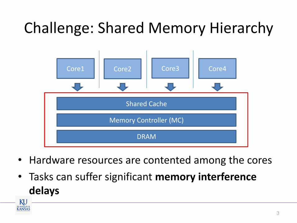
Challenge: Shared Memory Hierarchy
3
Core1 Core2 Core3 Core4
Memory Controller (MC)
Shared Cache
• Hardware resources are contented among the cores
• Tasks can suffer significant memory interference delays
DRAM

Memory Interference Delay • Can be extremely high in the worst-case
4
8.0
33.5
45.8
0
5
10
15
20
25
30
35
40
45
50
ARMCortex A15
IntelNahelem
IntelHaswell
solo
+ 1 co-runner
+ 2 co-runners
+ 3 co-runners
No
rma
lized
exe
cuti
on
tim
e
45.8X slowdown
DRAM
LLC
Core1 Core2 Core3 Core4
bench co-runner(s)
banks
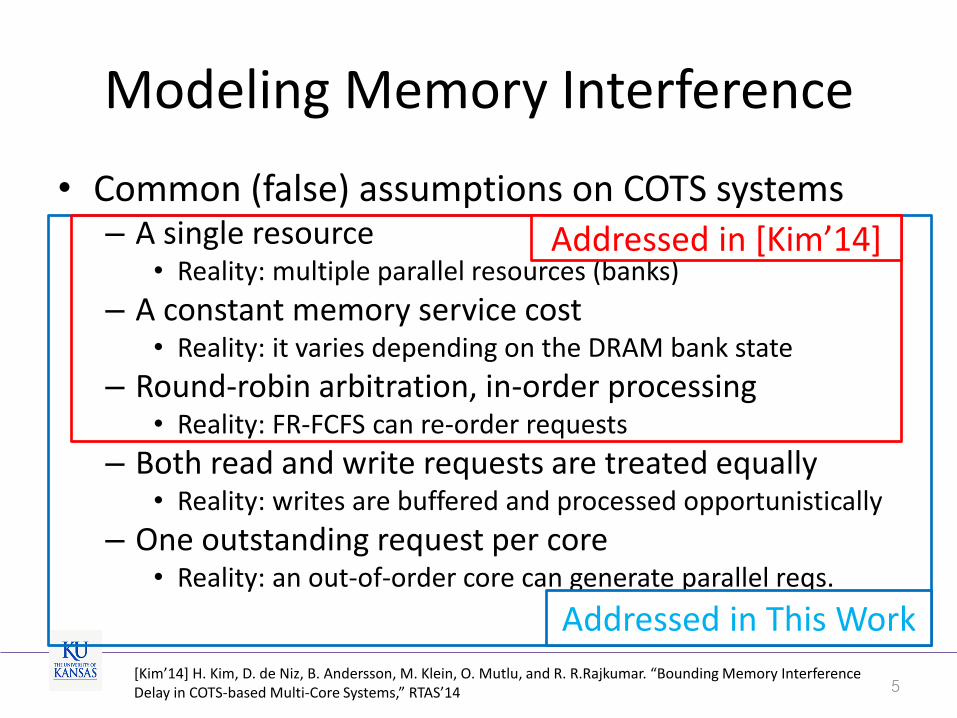
Modeling Memory Interference
• Common (false) assumptions on COTS systems – A single resource
• Reality: multiple parallel resources (banks)
– A constant memory service cost • Reality: it varies depending on the DRAM bank state
– Round-robin arbitration, in-order processing • Reality: FR-FCFS can re-order requests
– Both read and write requests are treated equally • Reality: writes are buffered and processed opportunistically
– One outstanding request per core • Reality: an out-of-order core can generate parallel reqs.
5
Addressed in This Work
Addressed in [Kim’14]
[Kim’14] H. Kim, D. de Niz, B. Andersson, M. Klein, O. Mutlu, and R. R.Rajkumar. “Bounding Memory Interference Delay in COTS-based Multi-Core Systems,” RTAS’14

Our Approach
• Realistic memory interference model for COTS systems – Memory-level parallelism (MLP) in COTS architecture
– Write-buffering and opportunistic batch processing in MC
• DRAM bank-partitioning – Reduce interference
• Delay analysis – Compute worst-case memory interference delay of the
task under analysis
6
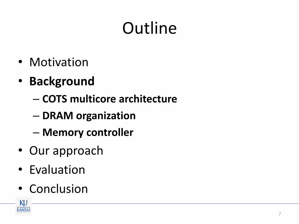
Outline
• Motivation
• Background
– COTS multicore architecture
– DRAM organization
– Memory controller
• Our approach
• Evaluation
• Conclusion
7
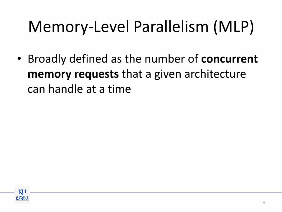
Memory-Level Parallelism (MLP)
• Broadly defined as the number of concurrent memory requests that a given architecture can handle at a time
8
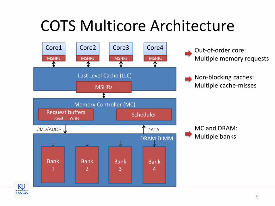
Last Level Cache (LLC)
DRAM DIMM
Memory Controller (MC)
Core1
Core2
Core3
Core4
Request buffers Read Write
Scheduler
MSHRs
CMD/ADDR DATA
COTS Multicore Architecture
Out-of-order core: Multiple memory requests
Non-blocking caches: Multiple cache-misses
MC and DRAM: Multiple banks
Bank 4
Bank 3
Bank 2
Bank 1
MSHRs MSHRs MSHRs MSHRs
9
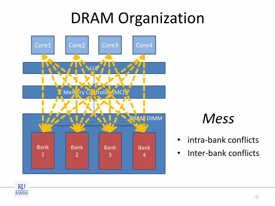
DRAM Organization
LLC
DRAM DIMM
Memory Controller (MC)
Bank 4
Bank 3
Bank 2
Bank 1
Core1 Core2 Core3 Core4
Mess
• intra-bank conflicts
• Inter-bank conflicts
10

DRAM Bank Partitioning
L3
DRAM DIMM
Memory Controller (MC)
Bank 4
Bank 3
Bank 2
Bank 1
Core1 Core2 Core3 Core4
• Private banking
– OS kernel allocates pages from dedicated banks for each core
Eliminate intra bank conflicts
11
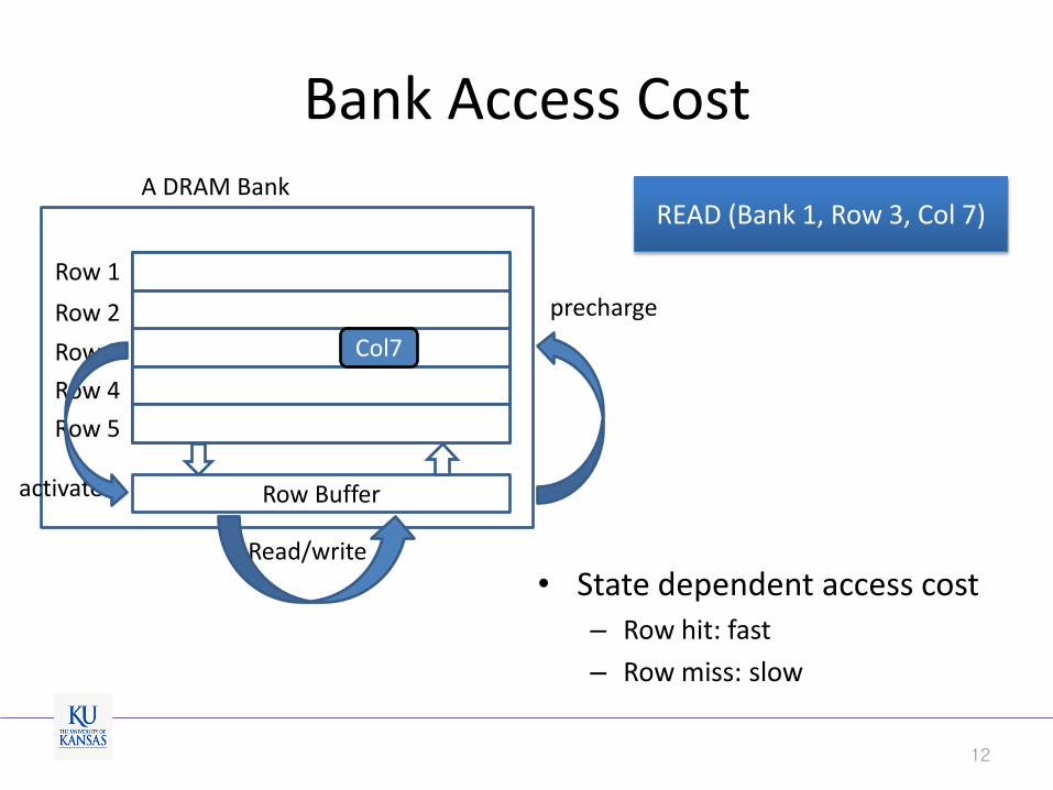
Bank Access Cost
Row 1
Row 2
Row 3
Row 4
Row 5
A DRAM Bank
Row Buffer activate
precharge
Read/write
• State dependent access cost – Row hit: fast
– Row miss: slow
READ (Bank 1, Row 3, Col 7)
Col7
12
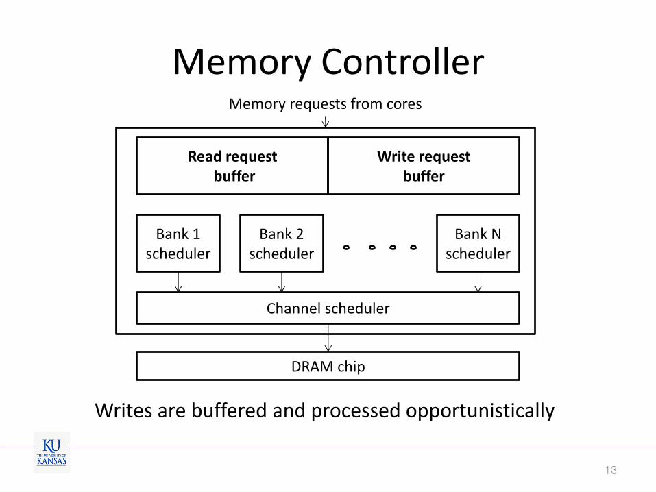
Memory Controller
13
Read request buffer
Write request buffer
Bank 1 scheduler
Channel scheduler
Bank 2 scheduler
Bank N scheduler
DRAM chip
Memory requests from cores
Writes are buffered and processed opportunistically
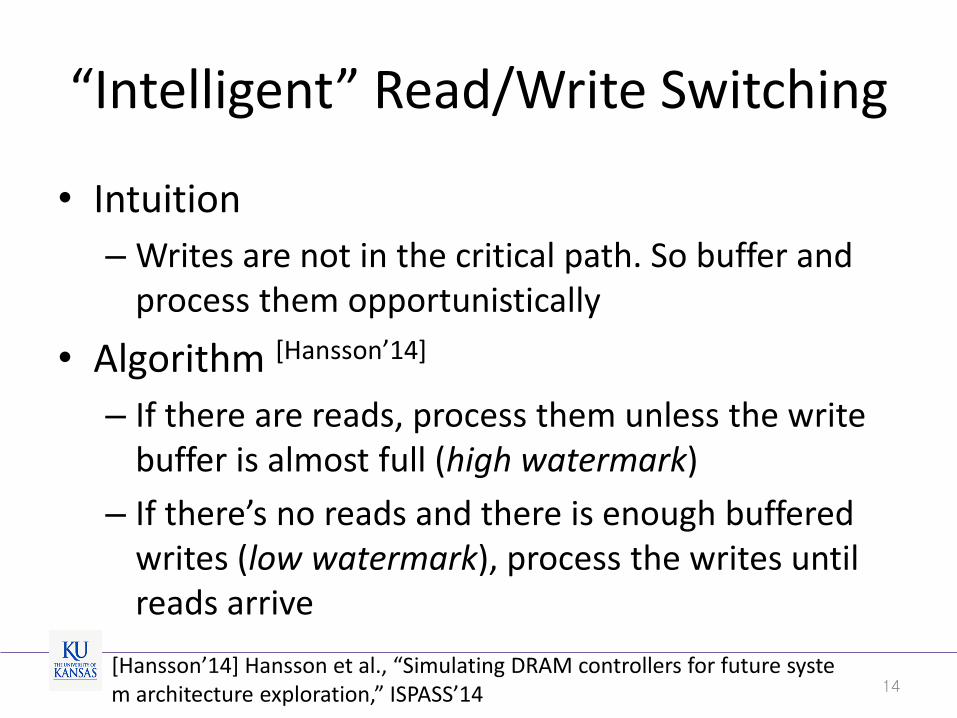
“Intelligent” Read/Write Switching
• Intuition
– Writes are not in the critical path. So buffer and process them opportunistically
• Algorithm [Hansson’14]
– If there are reads, process them unless the write buffer is almost full (high watermark)
– If there’s no reads and there is enough buffered writes (low watermark), process the writes until reads arrive
14 [Hansson’14] Hansson et al., “Simulating DRAM controllers for future system architecture exploration,” ISPASS’14
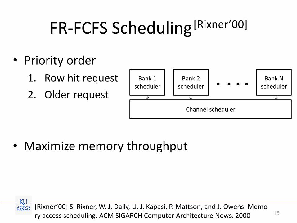
FR-FCFS Scheduling [Rixner’00]
• Priority order
1. Row hit request
2. Older request
• Maximize memory throughput
15
Bank 1 scheduler
Channel scheduler
Bank 2 scheduler
Bank N scheduler
[Rixner’00] S. Rixner, W. J. Dally, U. J. Kapasi, P. Mattson, and J. Owens. Memory access scheduling. ACM SIGARCH Computer Architecture News. 2000
Outline
• Motivation
• Background
• Our approach
– System model
– Delay analysis
• Evaluation
• Conclusion
16
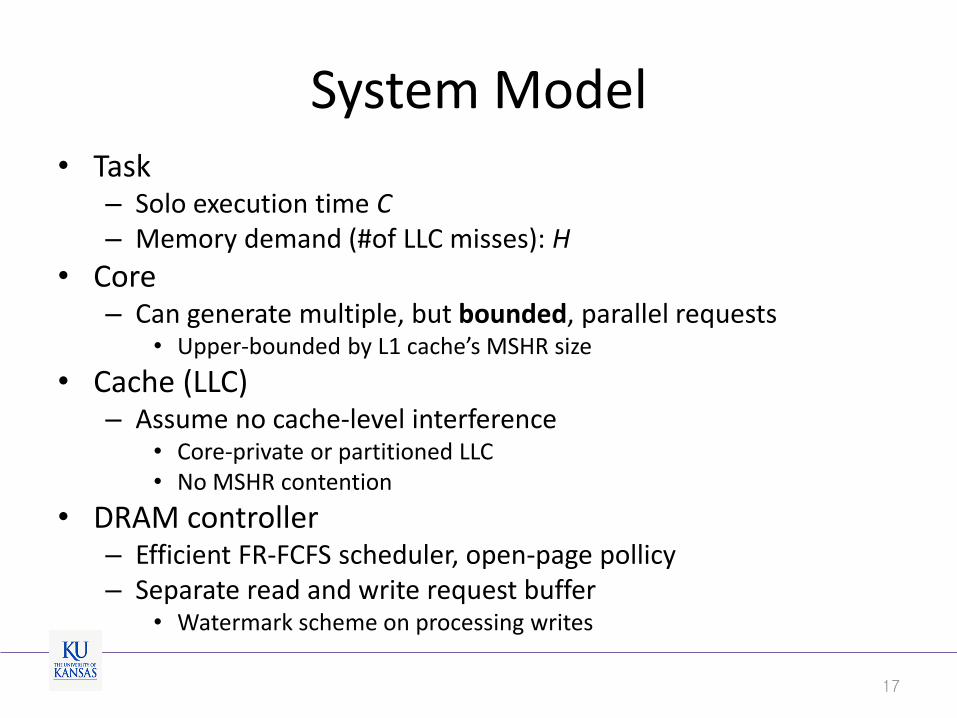
System Model • Task
– Solo execution time C – Memory demand (#of LLC misses): H
• Core – Can generate multiple, but bounded, parallel requests
• Upper-bounded by L1 cache’s MSHR size
• Cache (LLC) – Assume no cache-level interference
• Core-private or partitioned LLC • No MSHR contention
• DRAM controller – Efficient FR-FCFS scheduler, open-page pollicy – Separate read and write request buffer
• Watermark scheme on processing writes
17
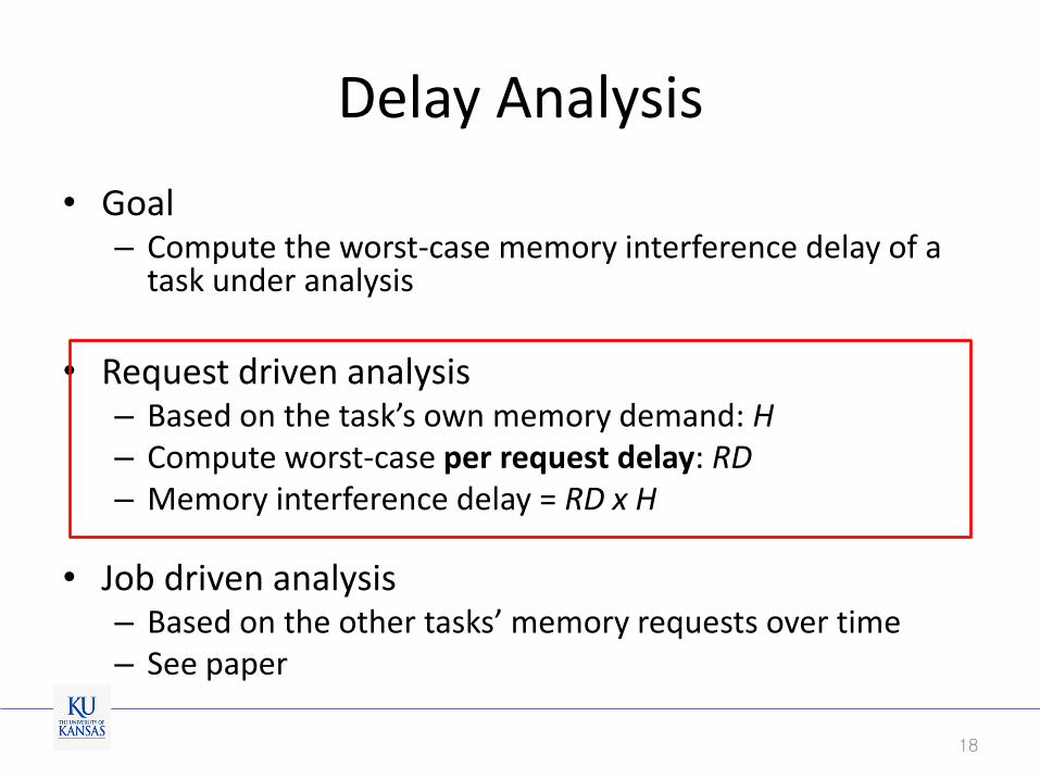
Delay Analysis
• Goal – Compute the worst-case memory interference delay of a
task under analysis
• Request driven analysis
– Based on the task’s own memory demand: H – Compute worst-case per request delay: RD – Memory interference delay = RD x H
• Job driven analysis – Based on the other tasks’ memory requests over time – See paper
18
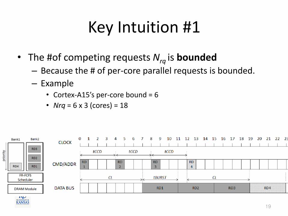
Key Intuition #1
• The #of competing requests Nrq is bounded – Because the # of per-core parallel requests is bounded.
– Example • Cortex-A15’s per-core bound = 6
• Nrq = 6 x 3 (cores) = 18
19
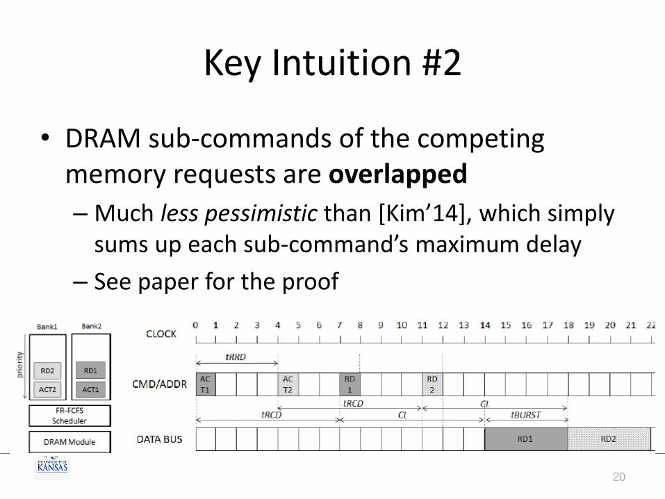
Key Intuition #2
• DRAM sub-commands of the competing memory requests are overlapped
– Much less pessimistic than [Kim’14], which simply sums up each sub-command’s maximum delay
– See paper for the proof
20
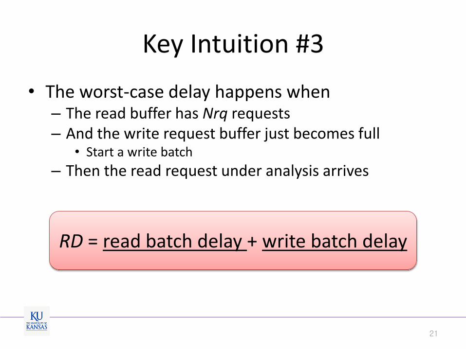
Key Intuition #3
• The worst-case delay happens when – The read buffer has Nrq requests – And the write request buffer just becomes full
• Start a write batch
– Then the read request under analysis arrives
21
RD = read batch delay + write batch delay
Outline
• Motivation
• Background
• Our approach
• Evaluation
• Conclusion
22
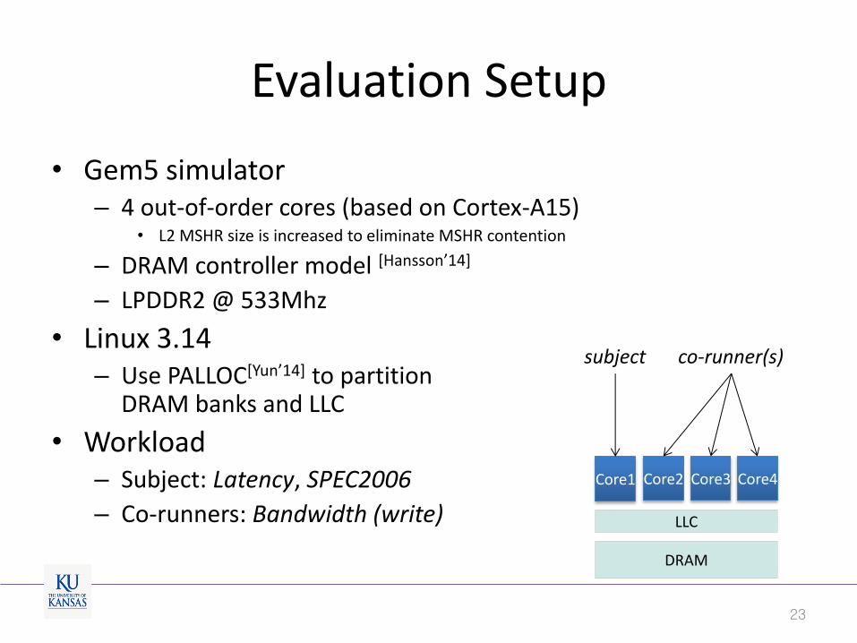
Evaluation Setup
• Gem5 simulator – 4 out-of-order cores (based on Cortex-A15)
• L2 MSHR size is increased to eliminate MSHR contention
– DRAM controller model [Hansson’14]
– LPDDR2 @ 533Mhz
• Linux 3.14 – Use PALLOC[Yun’14] to partition
DRAM banks and LLC
• Workload – Subject: Latency, SPEC2006
– Co-runners: Bandwidth (write)
23
DRAM
LLC
Core1 Core2 Core3 Core4
subject co-runner(s)

Results with the Latency benchmark
• Ours(ideal): Read only delay analysis (ignore writes) • Ours(opt): assume writes are balanced over multiple banks • Ours(worst): all writes are targeting one bank & all row misses
24
0
5
10
15
20
25
30
Measured [Kim'14] Ours(ideal) Ours(opt) Ours(worst)
No
rmal
ize
d R
esp
on
se T
ime
underestimate
overestimate
[Kim’14] H. Kim, D. de Niz, B. Andersson, M. Klein, O. Mutlu, and R. R.Rajkumar. “Bounding Memory Interference Delay in COTS-based Multi-Core Systems,” RTAS’14
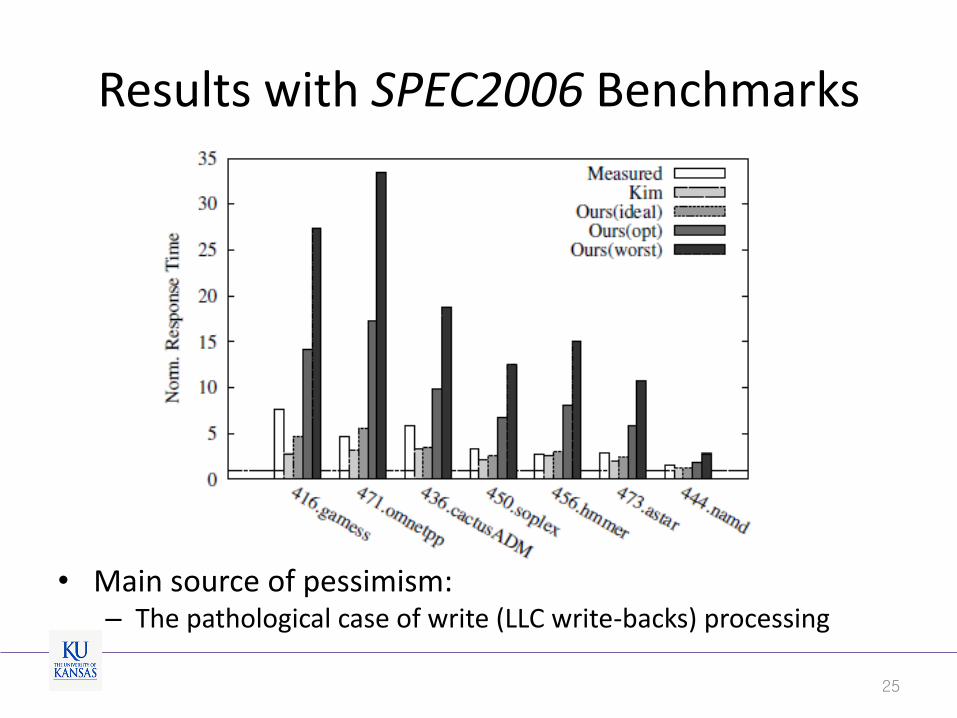
Results with SPEC2006 Benchmarks
• Main source of pessimism: – The pathological case of write (LLC write-backs) processing
25
Conclusion
• Memory interference delay on COTS multicore – Existing analysis methods rely on strong assumptions
• Our approach – A realistic model of COTS memory system
• Parallel memory requests • Read prioritization and opportunistic write processing
– Request and job-driven delay analysis methods • Pessimistic but still can be useful for low memory intensive tasks
• Future work – Reduce pessimism in the analysis
26
Thank You
27
Recommended