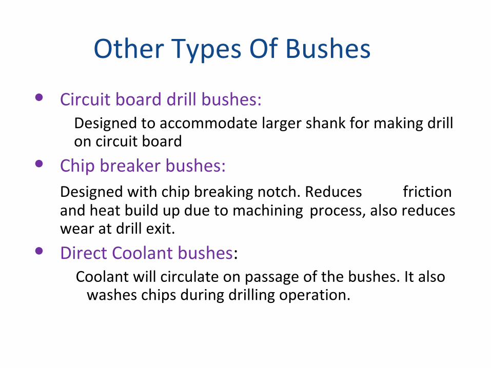
Other Types Of Bushes
Circuit board drill bushes:Designed to accommodate larger shank for making drill on circuit board
Chip breaker bushes:Designed with chip breaking notch. Reduces friction and heat build up due to machining process, also reduces wear at drill exit.
Direct Coolant bushes: Coolant will circulate on passage of the bushes. It also
washes chips during drilling operation.

Clearance between work piece and bushing
• There should be proper clearing to permit removal of chips.
C= Clearance between work piece and chip
= 0.5D for metals like cast iron that produce small chip
= D to 1.5 D for metals like steel tat produce long chip

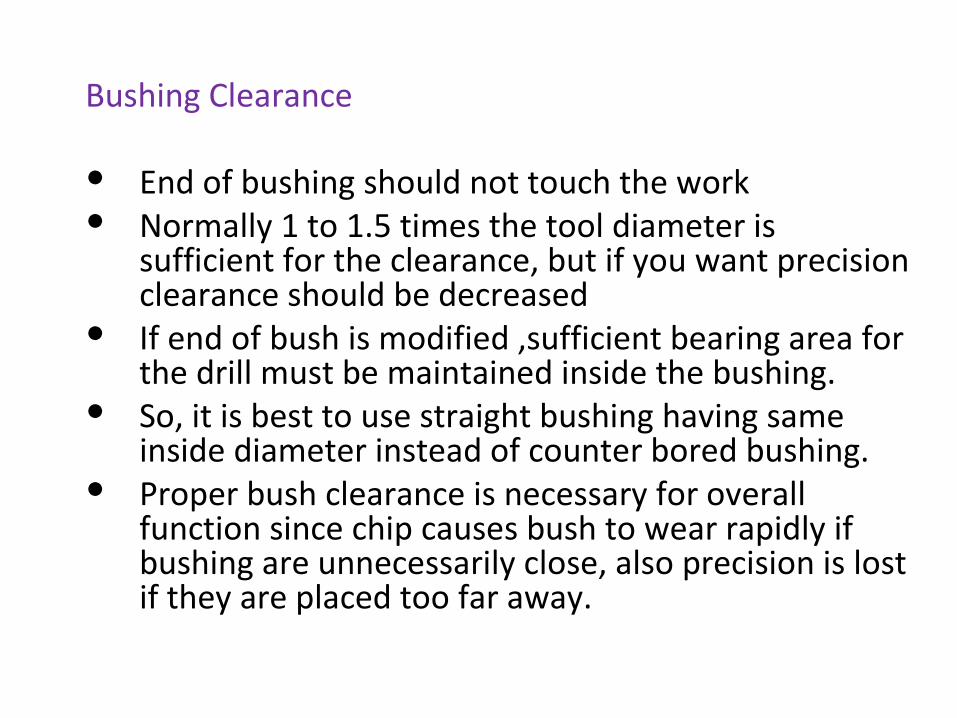
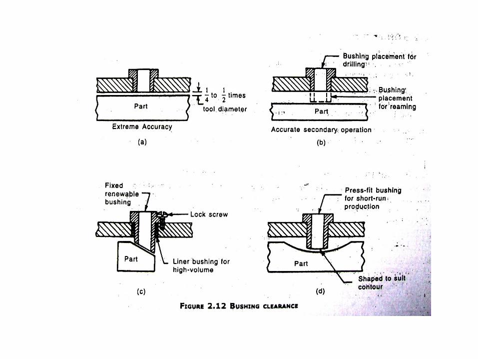
Bushing Clearance
End of bushing should not touch the work Normally 1 to 1.5 times the tool diameter is
sufficient for the clearance, but if you want precision clearance should be decreased
If end of bush is modified ,sufficient bearing area for the drill must be maintained inside the bushing.
So, it is best to use straight bushing having same inside diameter instead of counter bored bushing.
Proper bush clearance is necessary for overall function since chip causes bush to wear rapidly if bushing are unnecessarily close, also precision is lost if they are placed too far away.
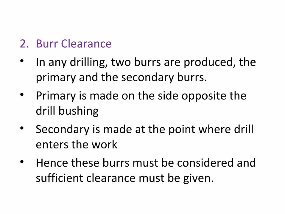
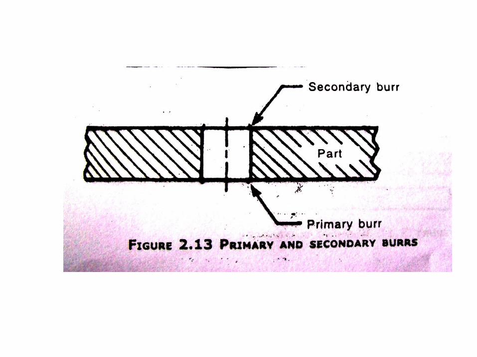
2. Burr Clearance• In any drilling, two burrs are produced, the
primary and the secondary burrs.• Primary is made on the side opposite the
drill bushing• Secondary is made at the point where drill
enters the work• Hence these burrs must be considered and
sufficient clearance must be given.

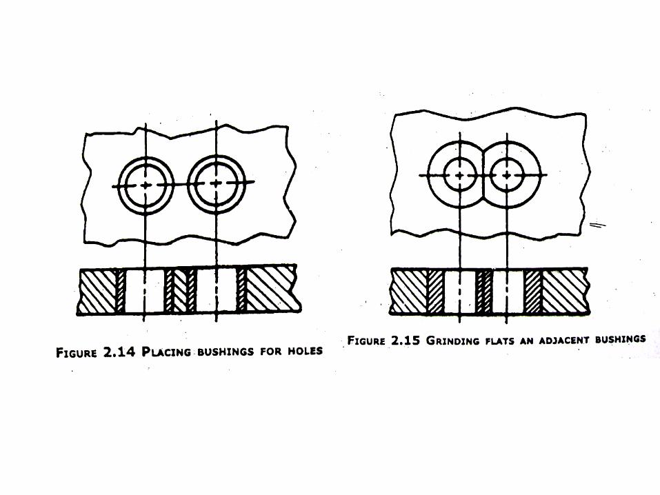
• Another problem is when holes are too close• In this case, we can use bushings of thin walls• Another alternative is to grind flats on
adjacent bushes• Also holes can be drilled and reamed and
bushing can be alternated from 1 hole to another
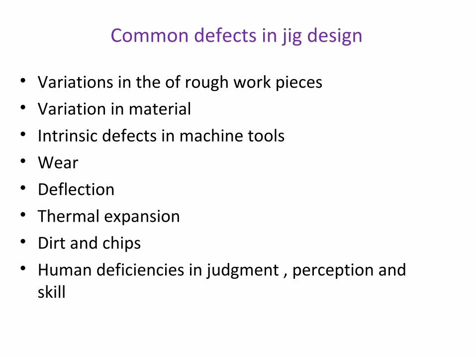
Common defects in jig design
• Variations in the of rough work pieces• Variation in material• Intrinsic defects in machine tools• Wear• Deflection• Thermal expansion• Dirt and chips• Human deficiencies in judgment , perception and
skill
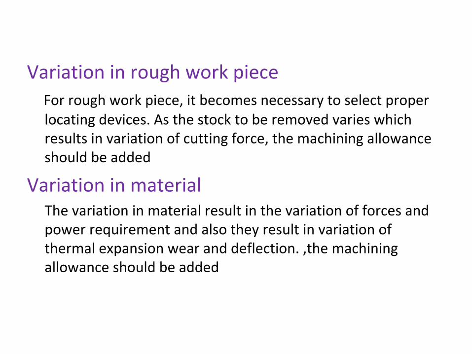
Variation in rough work piece For rough work piece, it becomes necessary to select proper
locating devices. As the stock to be removed varies which results in variation of cutting force, the machining allowance should be added
Variation in material The variation in material result in the variation of forces and
power requirement and also they result in variation of thermal expansion wear and deflection. ,the machining allowance should be added

Defect in tools As tools have tolerances, depending on the accuracy
required, it is customary to allow 10% tolerances of work pieces on jigs, fixtures and gauges.
Wear It also increases variations. So wear resistant materials should
be used for parts of jigs and fixtures Deflection Forces causing deflection may occur from handling, clamping
or cutting action. For this purpose, clamps should be never applied on the over hanging section of the work piece.
Thermal expansion The temperature dissipation should be minimized by adopting
sharp tools of proper shape, including provision for heat dissipation from tools and machine and employing controlled room temperature.

Dirt chips and burrs These directly interfere with work piece location, positioning
and gauging. For this, sharp corners should be avoided between locating surfaces as they catch dust are hard to clear.
Human deficiencies Jigs and fixtures should be designed to provide means of
achieving desired accuracy with lest skill and effort on the part of operator
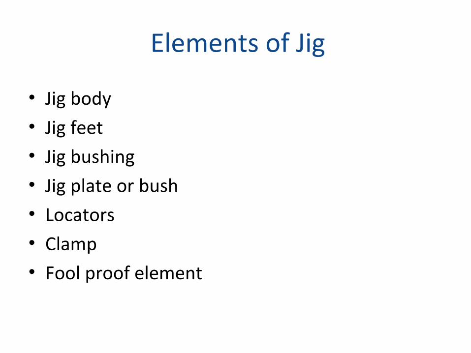
Elements of Jig
• Jig body• Jig feet• Jig bushing• Jig plate or bush• Locators• Clamp• Fool proof element
Jig body The jig body supports work piece and has locating and
clamping elements in it. It is provided with four jig feet and rests on the machine table.
Jig feet A jig feet which is not bolted to the machine table is provided
with four jig feet. They usually have flat bottom.Jig bushing For guiding drills, reamers and boring bars. Hardened steel jig
bushes are employed which are fixed in the jig plates. They
can be replaced at lower cost.
Jig plate or bush plate Usually the jig carries the jig bush for guiding the tools. The jig
plate may be rigidly constructed as a single unit of jig or it may be of leaf or latch type.
Locators Locators help work piece to rest in proper position in a jig. The
locators are usually detachable type.
Clamps Clamps are used for holding the work piece rigidly against all
disturbing forces. They also keep the work piece firmly in contact with locating pins of surfaces.
Fool proof element This element prevent work piece from being loaded wrongly
into the jig. The elements may be simple toulings pegs, cross pieces or pins.
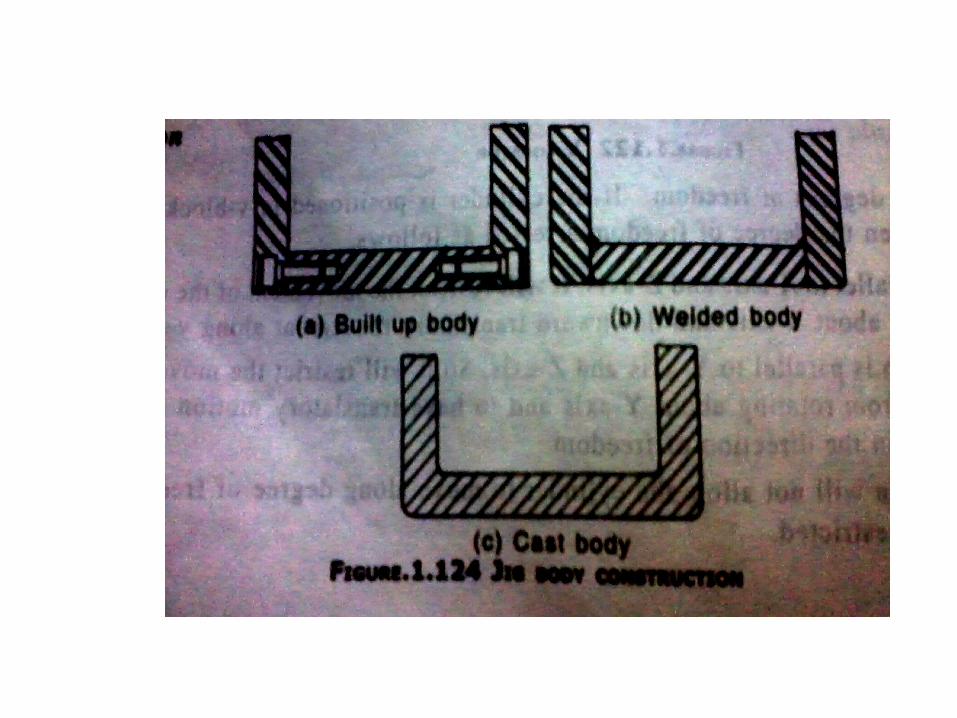
Construction of jigs
Jigs are constructed by one of the following methods• Built up construction • Welded construction • Cast construction
Built up construction
All the parts can be completely machined before assembly and worn parts can be easily be replaced. Jigs of this type are held together by socket head cap screws and dowels. The dowels are used to hold the part in alignment. A minimum of one screw and two dowels must be used to fasten each component to the jig body.
Welded construction
It is often used in constructing a drill jig. Welded jig must be stress relieved before machining because the stresses set up during welding will warp the jig. It may be faster to weld the components together and then machine them to finished size.
Cast construction Cast construction can be used for several jigs, when
every jig is made from a standard. Cast construction of a jig may be made to the required shape, size and finish.
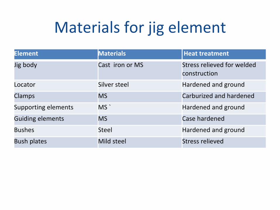
Materials for jig elementElement Materials Heat treatment
Jig body Cast iron or MS Stress relieved for welded construction
Locator Silver steel Hardened and ground
Clamps MS Carburized and hardened
Supporting elements MS ` Hardened and ground
Guiding elements MS Case hardened
Bushes Steel Hardened and ground
Bush plates Mild steel Stress relieved
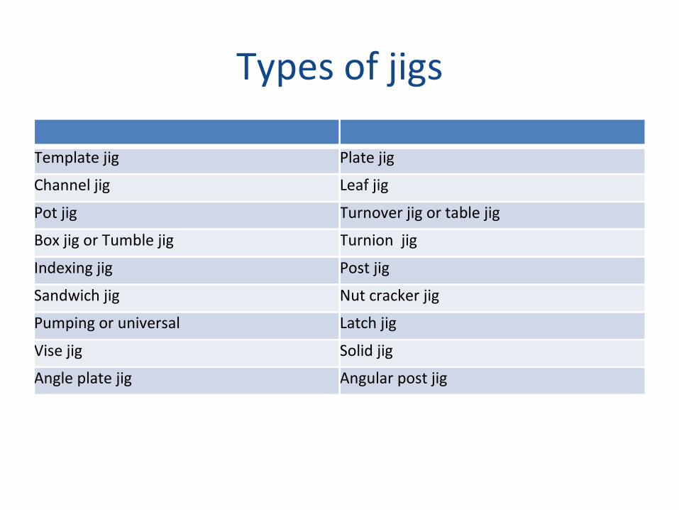
Types of jigs
Template jig Plate jig
Channel jig Leaf jig
Pot jig Turnover jig or table jig
Box jig or Tumble jig Turnion jig
Indexing jig Post jig
Sandwich jig Nut cracker jig
Pumping or universal Latch jig
Vise jig Solid jig
Angle plate jig Angular post jig
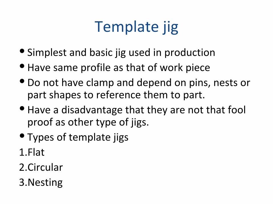
Template jig Simplest and basic jig used in production Have same profile as that of work piece Do not have clamp and depend on pins, nests or
part shapes to reference them to part. Have a disadvantage that they are not that fool
proof as other type of jigs. Types of template jigs1.Flat 2.Circular3.Nesting
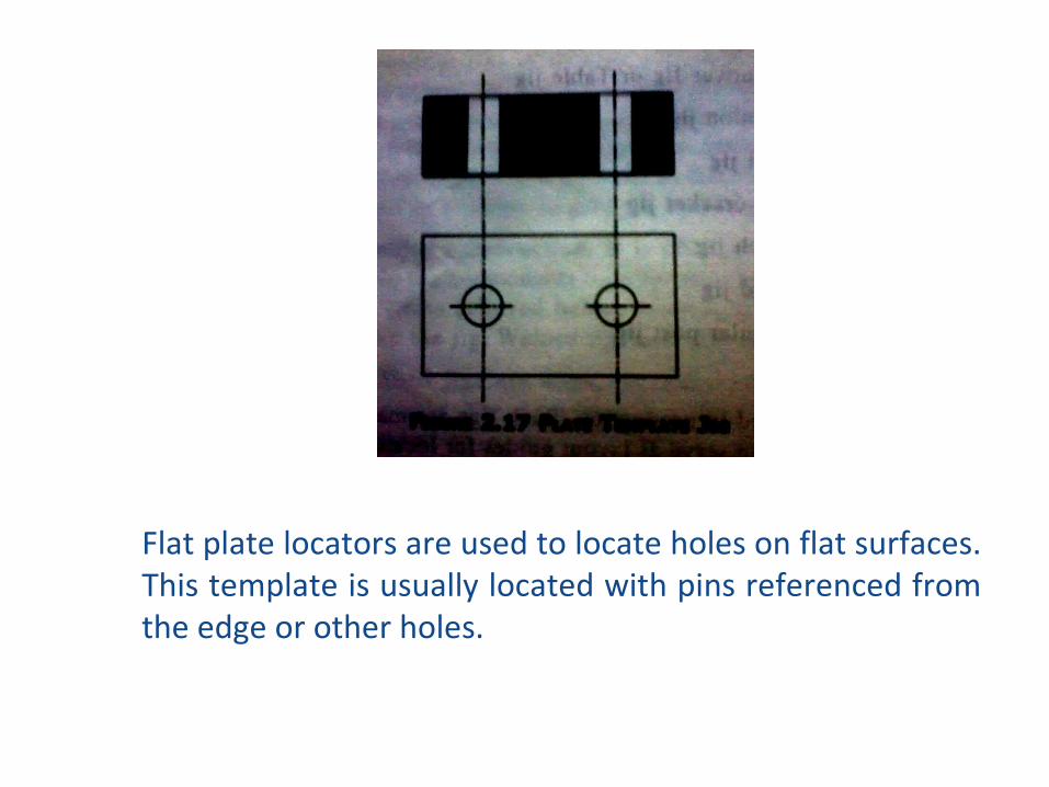
Flat plate locators are used to locate holes on flat surfaces. This template is usually located with pins referenced from the edge or other holes.
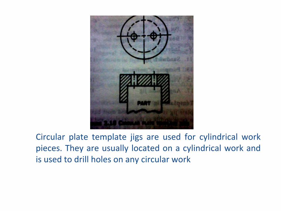
Circular plate template jigs are used for cylindrical work pieces. They are usually located on a cylindrical work and is used to drill holes on any circular work
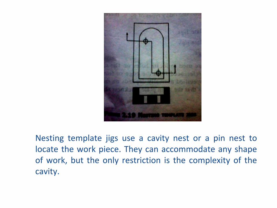
Nesting template jigs use a cavity nest or a pin nest to locate the work piece. They can accommodate any shape of work, but the only restriction is the complexity of the cavity.
Recommended

![2-[2] B.Sc. Workshop Technology III Yr. Sem. V & VI184.171.241.213/~bamuacin/syllabus/2016_17/Science/12.pdf · indexing mechanism, Drill Jig — Types of drill bushes, ... P.H.Joshi](https://img.dokumen.tips/doc/110x75/5b0069b37f8b9af1148ca000/2-2-bsc-workshop-technology-iii-yr-sem-v-vi184171241213bamuacinsyllabus201617science12pdfindexing.jpg)