University of Central Florida University of Central Florida
STARS STARS
Electronic Theses and Dissertations, 2004-2019
2015
Optical Fibers for Space-Division Multiplexed Transmission and Optical Fibers for Space-Division Multiplexed Transmission and
Networking Networking
Cen Xia University of Central Florida
Part of the Electromagnetics and Photonics Commons, and the Optics Commons
Find similar works at: https://stars.library.ucf.edu/etd
University of Central Florida Libraries http://library.ucf.edu
This Doctoral Dissertation (Open Access) is brought to you for free and open access by STARS. It has been accepted
for inclusion in Electronic Theses and Dissertations, 2004-2019 by an authorized administrator of STARS. For more
information, please contact [email protected].
STARS Citation STARS Citation Xia, Cen, "Optical Fibers for Space-Division Multiplexed Transmission and Networking" (2015). Electronic Theses and Dissertations, 2004-2019. 735. https://stars.library.ucf.edu/etd/735

OPTICAL FIBERS FOR SPACE-DIVISION MULTIPLEXED TRANSMISSION
AND NETWORKING
by
CEN XIA
B.S. Zhejiang University, China, 2009
A dissertation submitted in partial fulfillment of the requirements
for the degree of Doctor of Philosophy
in CREOL, The College of Optics & Photonics
at the University of Central Florida
Orlando, Florida
Summer Term
2015
Major Professor: Guifang Li

ii
© 2015 Cen Xia

iii
ABSTRACT
Single-mode fiber transmission can no longer satisfy exponentially growing capacity
demand. Space-division multiplexing (SDM) appears to be the only way able to dramatically
improve the transmission capacity, for which, novel optical fiber is one of the key technologies.
Such fibers must possess the following characteristics: 1) high mode density per cross-sectional
area and 2) low crosstalk or low modal differential group delay (DMGD) to reduce complexity
of digital signal processing. In this dissertation, we explore the design and characterization of
three kinds of fibers for SDM: few-mode fiber (FMF), few-mode multi-core fiber (FM-MCF)
and coupled multi-core fiber (CMCF) as well as their applications in transmission and
networking.
For the ultra-high density need of SDM, we have proposed the FMMCF. It combines
advantages of both the FMF and MCF. The challenge is the inter-core crosstalk of the high-order
modes. By applying a hole-assisted structure and careful fiber design, the LP11 crosstalk has been
suppressed down to -40dB per km. This allows separate transmission on LP01 and LP11 modes
without penalty. In fact, a robust SDM transmission up to 200Tb/s has been achieved using this
fiber.
To overcome distributed modal crosstalk in conjunction with DMGD, supermodes in
CMCFs have been proposed. The properties of supermodes were investigated using the coupled-
mode theory. The immediate benefits include high mode density and large effective area. In
supermode structures, core-to-core coupling is exploited to reduce modal crosstalk or minimize
DMGD. In addition, higher-order supermodes have been discovered in CMCFs with few-mode
iv
cores. We show that higher-order supermodes in different waveguide array configurations can be
strongly affected by angle-dependent couplings, leading to different modal fields. Analytical
solutions are provided for linear, rectangular and ring arrays. Higher-order modes have been
observed for the first time using S2 imaging method.
Finally, we introduce FMF to gigabit-capable passive optical networks (GPON). By
replacing the conventional splitter with a photonic lantern, upstream combining loss can be
eliminated. Low crosstalk has been achieved by a customized mode-selective photonic lantern
carefully coupled to the FMF. We have demonstrated the first few-mode GPON system with
error-free performance over 20-km 3-mode transmission using a commercial GPON system
carrying live Ethernet traffic. We then scale the 3-mode GPON system to 5-mode, which resulted
in a 4dB net gain in power budget in comparison with current commercial single-mode GPON
systems.

v
Dedicated to my family.

vi
ACKNOWLEDGMENTS
Throughout the six years of my Ph. D., I’ve received many helps. There is a saying, “if I
have seen a little bit further it is by standing on the shoulders of giants,” which I felt very true.
Every of my subtle achievements came from a lot of assistances.
First of all, I’d like to thank my advisor, Dr. Guifang Li. His great insights and step-by-step
guidance lead me into the field of fiber-optic communication. Dr. Li has been extremely patient
and helpful during my Ph. D. study and research. His rigorous academic attitude, deep
understanding and creative thinking have given me great influences. He has also provided me
with precious opportunities to collaborate with top-level institutes and companies. During the
collaboration, I was able to interact with prominent scholars. Without him, there is no way for
me to finish my Ph. D. and enter my future professional career so smoothly.
I also would like to give my great thanks to Dr. Xiang Liu, who is my mentor during my
internships in Bell Labs and Futurewei Technologies. I am so grateful that I had the chance to
work so closely with such a talented and helpful scholar. He has given me a big impact not only
in doing research but also how to work and live.
I’d like to thank Prof. Rodrigo Amezcua Correa and Dr. Jose Enrique Antonio-Lopez in
particular, who collaborate with our group on many projects. They have taught me a lot about
fiber design, fabrication and test. It wouldn’t be possible for me to have these accomplishments
if they are not here.
My mentors in Bell Labs, Dr. Nicolas K. Fontaine and Dr. Roland Ryf and my mentors in
Futurewei Technologies, Dr. Frank Effenberger and Dr. Naresh Chand have given me

vii
tremendous helps and guidance. Their enthusiasm and intelligence have motivated me to be more
initiative and agile in research.
I feel grateful to be in our group, where we always help and support each other, including
Dr. Xiaobo Xie, Dr. Ibrahim Ozdur, Dr. He Wen, Dr. Neng Bai, Dr. Likai Zhu, Bing Huang,
Huiyuan Liu and all my previous group members.
I’ve received valuable suggestions and great encouragement from all the members of my
dissertation committee: Prof. Ayman Abourady, Prof. Demetrios Christodoulides and Prof. M. G.
"Jim" Moharam and Prof. Thomas Wu. In addition, Prof. Demetrios Christodoulides and M.
Amin Eftekhar have made a great contribution to our invited paper about supermodes, which I do
appreciate.
There are so many people I own thanks to during my Ph. D.. I can never forget Prof. Shin-
Tson Wu and his wife Choyan Hsieh, who have taken care of me since the day I came to CREOL
and walked me through the toughest days of my life. And all my friends in CREOL, who lent me
equipment, shared knowledge with me and colored my life over the years.
Lastly but most importantly, I’d like to give my biggest thanks to my family: my husband
Zhenyue Luo, my parents and the one who guides me. They are always there for me. No matter
what I can always keep smiling, forget behind and reach forward, because love never fails.

viii
TABLE OF CONTENTS
LIST OF FIGURES ........................................................................................................................ x
LIST OF TABLES ........................................................................................................................ xv
LIST OF ABBREVIATIONS ...................................................................................................... xvi
CHAPTER 1 INTRODUCTION TO SPACE DIVISION MULTIPLEXING ......................... 1
1.1 Limit of Single-Mode Transmission ..................................................................................... 1
1.2 Space Division Multiplexed Transmission ........................................................................... 3
1.2.1 Core Multiplexing using Multi-Core Fibers .................................................................. 3
1.2.2 Mode Division Multiplexing using Few-Mode Fibers .................................................. 4
1.3 Dissertation Outline .............................................................................................................. 8
CHAPTER 2 FEW-MODE MULTI-CORE FIBERS FOR SDM TRANSMISSION ............ 10
2.1 Introduction ......................................................................................................................... 10
2.2 Fiber Design and Fabrication .............................................................................................. 11
2.2.1 Fiber Design ................................................................................................................. 11
2.2.2 Fiber Fabrication .......................................................................................................... 13
2.3 Fiber Characterization ......................................................................................................... 15
2.4 Initial Transmission Experiment ......................................................................................... 19
2.5 Collaborated 200Tb/s Transmission Experiment ............................................................... 20
CHAPTER 3 COUPLED MULTI-CORE FIBERS FOR SDM TRANSMISSION ............... 23
3.1 Introduction ......................................................................................................................... 23
3.2 Supermodes in Coupled Single-Mode Core Fibers ............................................................ 25
ix
3.2.1 Coupled-Mode Theory for Supermodes ...................................................................... 25
3.2.2 Design for Short-Distance Applications ...................................................................... 29
3.2.3 Design for long-distance applications .......................................................................... 32
3.3 Higher-Order Supermodes in Coupled Few-Mode Core Fibers ......................................... 37
3.3.1 Higher-Order Supermodes in a Two-Core Structure ................................................... 39
3.3.2 Higher-Order Supermodes in Linear-Array Structures ................................................ 43
3.3.3 Higher-Order Supermodes in 2D Rectangular-Array Structures ................................. 46
3.3.4 Higher-Order Supermodes in Ring-Array Structures .................................................. 49
3.3.5 Observation of Higher-Order Supermodes .................................................................. 53
CHAPTER 4 FEW-MODE PASSIVE OPTICAL NETWORKS ............................................. 2
4.1 Introduction and Background ............................................................................................... 2
4.2 Principle of Few-Mode PON ................................................................................................ 3
4.3 Low-Crosstalk Few-Mode PON ........................................................................................... 5
4.4 Demonstration of the First Few-Mode GPON System ......................................................... 8
4.5 Alternatives and Discussion ................................................................................................ 10
4.6 Scaling to 5-mode PON ...................................................................................................... 12
CHAPTER 5 SUMMARY ...................................................................................................... 18
APPENDIX: DERIVATIONS ..................................................................................................... 20
LIST OF REFERENCES .............................................................................................................. 23
x
LIST OF FIGURES
Figure 1-1. Cross-sectional view of a fabricated trench-assisted multi-core fiber and its index
profile .............................................................................................................................................. 4
Figure 1-2. Schematic of a step-index circular fiber with an increasing cross-sectional area and
profiles of supported modes along the fiber. .................................................................................. 5
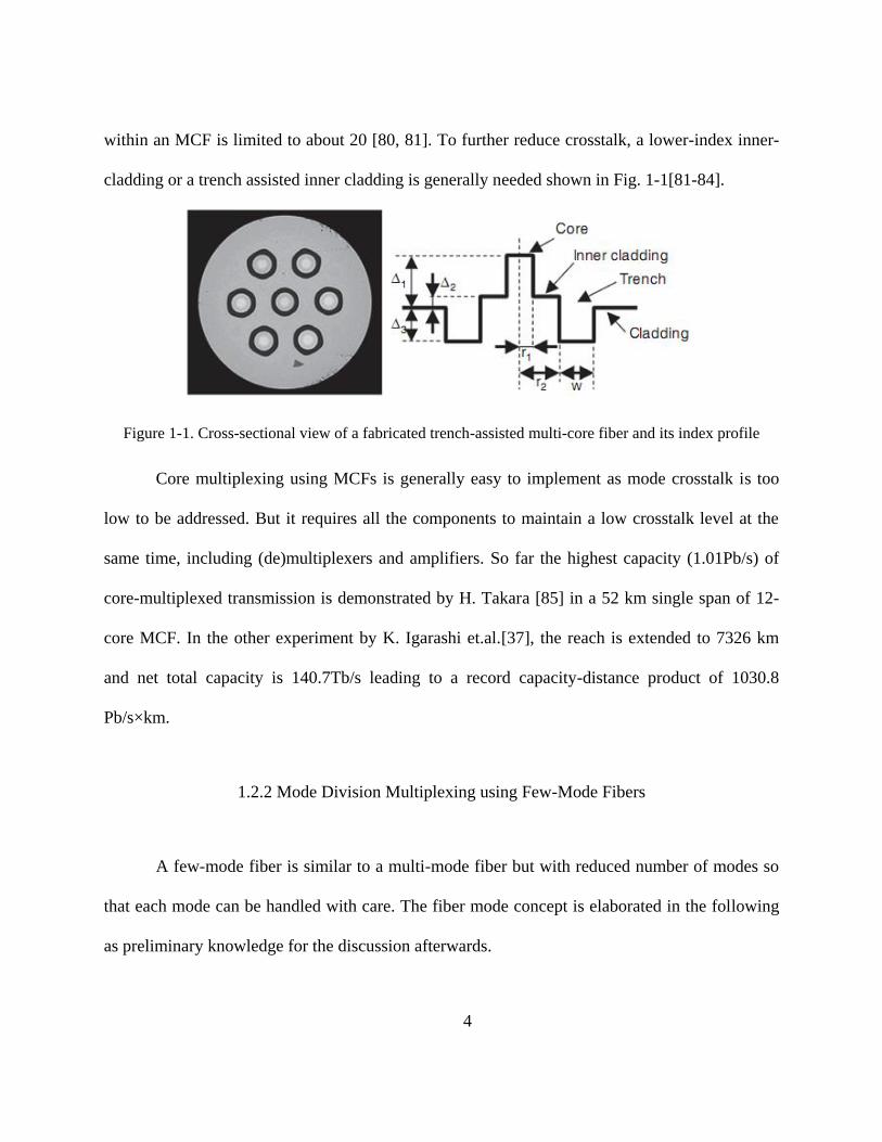
Figure 1-3. Schematic of (a) an ideal two-mode fiber in which the two parallel line represent two
orthogonal modes and (b) a real fiber that has distributed cross talk. ............................................ 7
Figure 2-1. Inter-core 11LP mode crosstalk between two adjacent cores of a hole-assisted few-
mode MCF as a function of the air hole-to-pitch ratio /d as well as that of a trench-assisted
few-mode MCF at λ=1550nm. ...................................................................................................... 13
Figure 2-2. Cross section of the fabricated FMMCF .................................................................... 14
Figure 2-3. The schematic setup for LP11 crosstalk measurement .............................................. 16
Figure 2-4. Simulated 11LP free-space excitation-induced crosstalk value as a function of the
propagation distance from phase plate to the FMMCF as well as the intensity pattern at FMMCF
facet ............................................................................................................................................... 18
Figure 2-5. (a) The setup for LP01 and LP11 transmission over 1km FMMCF (b) Q2 factor v.s.
OSNR for back-to-back, LP01 and LP11 transmission. ............................................................... 20
Figure 2-6. FMMCF PDM/WDM/SDM transmission experimental setup. (a) the entire
experimental setup; (b) the decorrelated wavelength spectrum after being interleaved by a
wavelength selective switch; (c) 3D waveguide facet; (d) FM-MCF facet which butt-coupled to
the 3D waveguide; (e) saturated camera image taken at the FM-MCF receiver side. .................. 22
Figure 3-1. Schematic of a coupled four-core fiber structure. ...................................................... 25

xi
Figure 3-2. Field distributions of the 1st (a), 2nd (b), 3rd (c) and 4th (d) supermodes for four-core
CMCFs. (Black lines indicate the boundaries of the cores) .......................................................... 28
Figure 3-3. Field distributions of the 1st (a), 2nd (b), 3rd (c), 4th (d), 5th (e) and 6th (f)
supermodes for the six-core CMCF. (Black lines indicate the boundaries of the cores) .............. 31
Figure 3-4. effA vs. effN for CMCFs and FMFs ( effN refers to the minimum effN for one mode
to any other mode); (b) Confinement factor vs. effN for CMCFs and FMFs. ............................ 32
Figure 3-5. (a) (b) (c) dc
dat V=1.6, 1.7 and 1.9. (d)
d dc
d d
at V=1.7. .................................... 34
Figure 3-6. (a) maximum DMGD vs. wavelength at V=1.707 @1.55μm and ∆=0.06%, (b) (c) (d)
field distribution of the 1st, 2nd and 3rd supermode of a three-core CMCF ............................... 36
Figure 3-7. Coupling between two arbitrarily oriented 11LP degenerate modes as a function of
their initial angles 1 and 2 . The arrow points to the position of zero coupling
1 2( 0, / 2) 0 between the 11xLP and 11yLP modes; the inset shows the coordinate system
of the two cores including reference axes and two initial angles. ................................................ 40
Figure 3-8. Modal fields of 01LP supermodes (a & b) and 11LP supermodes (c-f) of a basic two-
core structure. In-phase supermodes are shown in (a), (c) and (d) while out-of phase supermodes
are shown in (b), (e) and (f). ......................................................................................................... 43
Figure 3-9. Modal fields of 01LP supermodes (a-d) and 11LP supermodes (e-l) of a 4-core linear-
array structure. .............................................................................................................................. 45
Figure 3-10. (a) A rectangular array of waveguides. The 01
LP mode in each waveguide cross-
talks with nearest neighbors along the horizontal and vertical directions as well as with diagonal

xii
elements. (b) Coupling interactions in this same array when each element involves instead the
11LP mode. .................................................................................................................................... 47
Figure 3-11. (a) Scheme of mode basis selection for 11LP supermode analysis of a 4-core grid-
array structure; modal fields of 01LP supermodes (a-d) and 11LP supermodes (e-l) of a 4-core grid-
array structure computed using COMSOL ................................................................................... 48
Figure 3-12. (a) Scheme of mode basis selection for 11LP supermode analysis of a 3-core ring-
array structure; modal fields of 01LP supermodes (b-d) and 11LP supermodes (e-j) of a 3-core ring-
array structure computed using COMSOL. .................................................................................. 53
Figure 3-13. (a) Schematic of S2 imaging setup using a tunable laser and a CCD camera; (b)
wavelength-scanning results of the multi-path interference pattern for one pixel of the CCD
camera and (c) the result of intensity vs. differential group delay (DGD) after taking Fourier
transform of (b). Inset of (c) shows the resolved LP modes after picking the information for
every pixel at the corresponding DGDs of different modes and mapping them together. ........... 56
Figure 3-14. (a) Cross-sectional view of the fabricated coupled-3-core fiber and (b-j) resolved
supermodes of the fabricated coupled-3-core fiber shown in amplitude (x1) and phase (x2): (b)
the fundamental 01LP supermode; (c, d) the degenerate pair of 01LP supermodes; (d) the
fundamental 11LP supermode; (e, f) the first degenerate pair of 11LP supermodes; (g) the fourth
11LP supermode; (h, i) the second degenerate pair of 11LP supermodes. .......................................... 1
Figure 4-1. PON architectures with low upstream loss using (a) multiple feeder fibers and a
multimode combiner (MC); and (b) a single FMF with a mode transforming coupler (MTC). ..... 3

xiii
Figure 4-2. (a) The cross-section of the mode-selective lantern output; (b) measured LP01,
LP11a & LP11b intensity patterns at the lantern near-field, far-field and the end of lantern-to-
20km FMF. ..................................................................................................................................... 5
Figure 4-3. (a) Picture of the few-mode segment of the ODN; (b) measured LP01, LP11a and
LP11b impulse responses of the few-mode ODN segment. ........................................................... 7
Figure 4-4. Schematic of a few-mode GPON system using a 20km FMF and a mode-selective
lantern for upstream transmission. OLT: commercial optical line terminal; ONUs: commercial
optical network units. ...................................................................................................................... 9
Figure 4-5. (a) BER measurements of the few-mode ODN segment; (b) eye diagrams of the cases
of B2B (with SSMF), 20km LP01, LP11a and LP11b transmission. ........................................... 10
Figure 4-6. Simulation results of modal group delay for 10-mode fiber design of trench-assisted
graded-index profile. Inset: the FMF index profile with parameters indicated. ........................... 12
Figure 4-7. (a) The cross-sectional view of the photonic lantern output. (b) Intensity patterns of 5
modes for the near-field and far-field output of the photonic lantern and after 20km propagation
via the FMF at 1.3μm. ................................................................................................................... 13
Figure 4-8. Index profile of the few-mode fiber. Inset: cross-sectional view. .............................. 14
Figure 4-9. Impulse measurements and (b) eye diagrams of the 5-mode optical link composed of
the photonic lantern spliced with 20km FMF spool. .................................................................... 15
Figure 4-10. BER measurements of the 5-mode optical link ........................................................ 16
Figure 4-11. Schematic of 5-mode GPON system using the PL spliced to 20km FMF for
upstream transmission with commercial Huawei OLT and ONUs. OLT: optical line terminal;
ONU: optical networking unit; PL: photonic lantern. Red line represents 1490nm downstream

xiv
transport; blue line stands for 1310nm downstream transport; and gray line corresponds to:
bidirectional transmission. ............................................................................................................ 17

xv
LIST OF TABLES
Table 2-1. Parameters of Fabricated FMMCF .............................................................................. 14
Table 2-2. Simulated and Measured characteristics of Fabricated FMMCF ................................ 15
xvi
LIST OF ABBREVIATIONS
Aeff Effective area
CMCF Coupled Multi-Core Fiber
DEMUX Demultiplexer
DMGD Differential Modal Group Delay
DMGDS Differential Modal Group Delay Slope
DSP Digital Signal Processing
EDFA Erbium-Doped Fiber Amplifier
FMF Few-Mode Fiber
FMMCF Few-Mode Multi-Core Fiber
GI Graded Index
GPON Gigabit-capable Passive Optical Network
MC Multimode Combiner
MCF Multi-Core Fiber
MDL Mode-Dependent Loss
MDM Mode Division Multiplexing
MIMO Multiple-Input-Multiple-Output
MMF Multi-Mode Fiber
MTC Mode Transforming Coupler
MUX Multiplexer
Neff Effective index
ODN Optical Distribution Network

xvii
OLT Optical Line Terminal
ONU Optical Network Unit
PL Photonic Lantern
PON Passive Optical Network
QAM Quadrature Amplitude Modulation
SDM Space Division Multiplexing
SFP Small Form-factor Pluggable transceiver
SMF Single-Mode Fiber
SNR Signal-to-Noise Ratio
TDM Time Division Multiplexed
WDM Wavelength Division Multiplexing
XT Crosstalk

1
CHAPTER 1 INTRODUCTION TO SPACE DIVISION
MULTIPLEXING
1.1 Limit of Single-Mode Transmission
Optical fiber communication is the backbone for the telecommunications infrastructure
that supports the internet. Fueled by emerging bandwidth-hungry applications and the increase in
computer processing power that follows the Moore’s Law, the internet traffic has sustained an
exponential growth in the past and this trend is expected to continue for the foreseeable future. It
is well known that the capacity of a communication channel cannot exceed the Shannon limit, In
the past two decades, the internet traffic demand was mainly met by the wavelength-division
multiplexing (WDM) technology [1], which can increase the spectral bandwidth of the fiber-
optic communication channel by two orders of magnitude. It should be noted that the spectral
bandwidth of the fiber-optic communication channel can be further increased by exploiting the
low-loss transmission window of the optical fiber beyond the C and L bands. However, this
bandwidth expansion is limited to below one order of magnitude. Furthermore, lack of an
integrated amplification platform makes such a system unattractive from a technical and
economic perspective.
Recently, coherent detection has attracted much attention to provide capacity increase for
optical fiber communication systems [2]. Coherent detection can maximize the signal-to-noise
ratio (SNR) of the fiber-optic communication channel in comparison with direct detection. High
SNR enables high-spectral efficiency quadrature amplitude modulation (QAM) that transmits

2
information in both the amplitude and phase of the optical signal. Digital coherent fiber-optic
communication systems have recently become commercially available. Further increase in SNR
can only be achieved by increasing the signal power. However, the increase in channel capacity
scales logarithmically with the increase in signal power. This logarithmical channel capacity
scaling ultimately cannot meet the demand of exponential traffic growth from a technical
perspective as well as the perspective of power consumption per bit. In addition, fiber
nonlinearity imposes an upper limit on how much power that can be transmitted in a fiber.
Digital coherent optical communication does make polarization multiplexing practical, providing
a factor of two increase in channel capacity.
While it might be impossible to provide exponential growth in optical fiber
communication capacity to match the exponential growth in capacity demand, multiplicative
growth in optical communication capacity, for example using WDM, has satisfied traffic
demand in the past. As today’s WDM coherent optical communication has already taken
advantage of all degrees of freedom of a lightwave in a single-mode fiber (SMF), namely
frequency, polarization, amplitude, and phase, further multiplicative growth has to explore new
degrees of freedom that do not exist in single-mode fibers. Similar to the multiple-input-
multiple-output (MIMO) architecture in wireless communication, space is the degree of freedom
that is being considered for optical fiber communication beyond WDM. Space-division
multiplexing, including mode-division multiplexing (MDM) using multimode fibers or few-
mode fibers (FMF) [3-31] and/or core multiplexing using multi-core fibers (MCF) [32-71], has
attracted much attention in the last three to five years for the next multiplicative capacity growth
for optical communication [72-76].
3
1.2 Space Division Multiplexed Transmission
In optical fiber transmission, two SDM schemes have been proposed. These are (i) core
multiplexing using multicore fibers (MCF), where a single strand of glass fiber contains a
number of independent single- (or multi-) mode cores each capable of communicating optical
signals; and (ii) mode division multiplexing (MDM) using multimode fibers (MMF) or few-
mode fibers (FMF), where a single strand of fiber has one core with sufficiently large cross-
section area to support a number of independent guiding modes.
1.2.1 Core Multiplexing using Multi-Core Fibers
Mode coupling, or called mode crosstalk is a major and fundamental obstacle for SDM
transmission, which is unavoidable after long-distance propagation within imperfect fibers. One
important reason that makes MCF a strong candidate for high capacity SDM transmission is that
mode crosstalk is maintained low enough within MCFs, not to cause any noticeable signal
penalty even after hundreds, or thousands of kilometers transmission. MCF has been used in
fiber lasers for a long time. But only in the latest years, MCF has been introduced to optical
transmission due to high spatial density with low loss and low crosstalk [77-79]. For each single
core of MCFs, single mode condition is still applied. The crosstalk level is determined by the
core-to-core distance, the core index and radius, as well as the cladding index profile. The core
density is dominated by the core-to-core distance (or called pitch). However, the maximum
cladding diameter is restricted by mechanical properties of silica, causing that the number of core
4
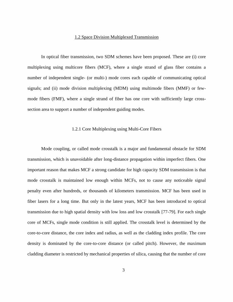
within an MCF is limited to about 20 [80, 81]. To further reduce crosstalk, a lower-index inner-
cladding or a trench assisted inner cladding is generally needed shown in Fig. 1-1[81-84].
Figure 1-1. Cross-sectional view of a fabricated trench-assisted multi-core fiber and its index profile
Core multiplexing using MCFs is generally easy to implement as mode crosstalk is too
low to be addressed. But it requires all the components to maintain a low crosstalk level at the
same time, including (de)multiplexers and amplifiers. So far the highest capacity (1.01Pb/s) of
core-multiplexed transmission is demonstrated by H. Takara [85] in a 52 km single span of 12-
core MCF. In the other experiment by K. Igarashi et.al.[37], the reach is extended to 7326 km
and net total capacity is 140.7Tb/s leading to a record capacity-distance product of 1030.8
Pb/s×km.
1.2.2 Mode Division Multiplexing using Few-Mode Fibers
A few-mode fiber is similar to a multi-mode fiber but with reduced number of modes so
that each mode can be handled with care. The fiber mode concept is elaborated in the following
as preliminary knowledge for the discussion afterwards.

5
Figure 1-2. Schematic of a step-index circular fiber with an increasing cross-sectional area and profiles of
supported modes along the fiber.
In MDM, we explore other modes other than the fundamental mode that can be supported
in optical fibers. Figure 1-2 schematically illustrates a step-index circular fiber with an increasing
cross-sectional area. This fiber will always support the fundamental mode, the 01LP mode,
characterized by its propagation constant 01 and the normalized mode profile 01( , )r such that
the power contained in the mode 01 01 01( , )exp{ [ ]} A r i t z is2
01| |A . When the fiber
diameter is increase to a point where the V number, 2 2
1 2(2 / ) V a n n , of the fiber is
greater than 2.405, the fiber can guide light in the next higher order mode, the 11LP mode,
characterized by its propagation constant 11 and the normalized mode profile 11( , )r . The
11LP mode has a two-fold degeneracy, rotated by090 illustrated in Fig. 1-2. Fibers guide light
using a high-index core and low-index cladding, which can be intuitively understood as by
means of total internal reflection at the core-cladding boundary. In step-index fiber, the refractive
index 1n is uniformly distributed across the core surrounded by a cladding with refractive index
n1
n2
2 2
1 2
22.405V a n n
Mode
Profiles
LP11bLP11aLP01
2aFiber
5.52V

6
2n . The propagation constant of any guide mode is thus bounded by 1 0 2 0,n k n k where 0k is
the propagation constant of light in vacuum. In typical fiber used for optical communication, the
relative index difference defined by 1 2 1/ n n n is less than 10-2
, therefore, fiber modes are
weakly guided. Under the weakly-guided approximation, the vectorial modes of the fiber can be
simplified using linearly polarization (LP) modes whose transverse field in the core is of the
form
, cos
p r
y y
p r
J k aE r E a p
J k r ( 1-1 )
where a is the radius of the core, 1/2
2 2 2
1 rk k n and p is a non-negative integer
referred to as the azimuthal mode number. For the same p value, rk can take on discrete values,
labeled by a non-negative integer q corresponding to the number of zero crossings of the field
along radial direction. The LP modes can be labeled as pqLP , each having two-fold degeneracies
in polarizations in x and y , and for 0p two fold degeneracies in spatial orientations separated
by a rotation of / p . The total number of modes of the step index core fiber is approximately
[86]
21
2M V .
By definition, modes supported by the fiberare orthonormal, i.e.,
* rs pq pr qsrdrd ( 1-2 )
which is the basis for mode-division multiplexing: transmitting and receiving
independent information simultaneously in each fiber mode.
7
Figure 1-3. Schematic of (a) an ideal two-mode fiber in which the two parallel line represent two
orthogonal modes and (b) a real fiber that has distributed cross talk.
The concept of MDM has been around for a very long time [87] but has not been pursued
until recently. The reason is that the orthogonality of modes can only be maintained in practical
application for a very short distance because of crosstalk among modes due to fiber
imperfections, bending and twisting as shown in Fig. 1-3. Here we discuss the origin of the mode
coupling first before going to the solutions and applications. Within the degenerate mode group
having the same propagation constant, the modes couple to each other when the index
distribution of the fiber deviates from the ideal circular-symmetric distribution. For the non-
degenerate modes, mode coupling is introduced due to fiber longitudinal variations. Such a
variation can be caused by fiber manufacturing process as well as micro- and macro-bending of
the fiber. Therefore the coupling is random in both strength and location and thus has to be dealt
statistically. Furthermore, because the non-degenerate modes propagate at different velocities,
the signal sent into the modes would accumulate a differential modal group delay (DMGD)
eventually at the end of fiber as well as the mode coupling, which is a major obstacle for MDM
transmission. There are several ways to address the problem. One solution widely used for long-
distance high capacity transmission is to adopt MIMO digital signal processing (DSP) to
compensate the penalty caused by mode coupling as well as the DMGD, similar to the MIMO
technique used in wireless communication. Basically, the compensation is to invert the coupling
matrix in the electronic domain since coherent detection is able to get both intensity and phase
LP01
LP11
01
11 in
A
A
01
11 out
A
A
,1mLP01
LP11A B
(a) (b)

8
information of the signal. But the algorithm complexity and required memory length is always a
big concern even though a lot of good efforts have been put in [28, 88-90]. Another way to deal
with the mode coupling is to transmit the same data in the mode group where the DMGD within
the group is reduced to be much less than the symbol period so that the mode coupling itself
would no longer be a problem. The DMGD can be minimized by careful fiber design [91, 92] or
compensated by optical fiber with the opposite sign of DMGD [93, 94], both of which has been
investigated intensively. Besides, the mode coupling also can be decreased by careful fiber
design, for example increasing the propagation constant difference of the modes so that small
perturbations would have less impact. Other than the mode coupling problem, MDM
transmission also requires high performance (de)multiplexer [95-97], efficient amplification [98,
99], mature splice technique etc [100]. All of them need to be taken care of to give a final
integrated high capacity transmission.
1.3 Dissertation Outline
The outline of the proposal report is laid out as follows:
In Chapter 1, Introduction presents the motivation, background and organization of the
dissertation.
In the chapter 2, the motivation using FMMCF for high capacity SDM system is
explained after a brief introduction of the current dilemma using few-mode fibers (FMFs) and
multi-core fibers (MCFs) separately. By applying hole-assisted structure and careful fiber design,

9
we show that both high mode density and low crosstalk can be achieved in a FMMCF, which is
then fabricated, tested and applied for 1km transmission enabling petabits capacity.
Chapter 3 shows our study of using CMCFs as another candidate for high capacity SDM,
where mode coupling (sometimes called crosstalk) is taken advantaged instead of being avoided.
First, we demonstrate that optical properties can be engineered by proper design of coupled
single-mode core structure. We then move on to study the higher-order supermodes in CMCFs
with few-mode cores, which can be predicted by the coupled-mode theory with angle-dependent
couplings. Analytical description for higher-order supermodes in different array configurations
are provided, including linear, square and ring array lattices. We also present an experimental
observation of higher-order supermodes in a coupled 3-core fiber.
Chapter 4 focuses on applying SDM in commercial access transmission. In this chapter,
we proposed the use of space-division multiplexing (SDM) in a single few-mode fiber (FMF),
acting as the feeder fiber in the optical distribution network (ODN), to effectively eliminate the
upstream combining loss. Moreover, this concept has been realized by using a commercial
GPON system carrying live Ethernet traffic, achieving the first reported few-mode GPON. The
principle and alternative schemes are discussed as well as a horizon for future works. In addition,
a 5-mode PON experiment is discussed with a record net gain of 4dB as an important extended
work.
Chapter 5 is dedicated to summarize the above works.

10
CHAPTER 2 FEW-MODE MULTI-CORE FIBERS FOR SDM
TRANSMISSION
2.1 Introduction
Multi-core fibers (MCF) and few-mode fibers (FMF) are transmission fiber candidates
for space-division multiplexing (SDM) [59, 88]. MCFs with lower crosstalk and long-distance
transmission in such MCFs have been reported [59, 101]. Transmission in FMFs using up to 5
spatial modes including amplified transmission has also been demonstrated [8]. One of the main
goals of SDM is to provide orders of magnitude increase in transmission capacity by increasing
the number of space channels. For MCFs demonstrated so far, each core supports only the
fundamental mode. The number of cores is limited by the desired low crosstalk at sufficiently
large core pitch and the maximum fiber cladding diameter (~225microns) from mechanical
considerations. The largest number of cores demonstrated for a MCF so far is 19 [66]. Although
it is not difficult to increase the number of spatial modes for FMFs, there are some disadvantages
associated with FMF with a large number of spatial modes. First, the confinement factor and
consequently the bending loss of the higher-order modes will be larger than the lower-order
modes. Second, multiplexing and demultiplexing of a large number of modes are complicated
and generally introduce more losses. In order to achieve higher capacity for future SDM, the
number of spatial channels per fiber needs to be further increased from MCFs and FMFs
demonstrated so far. Therefore, the authors have designed and fabricated a few-mode MCF
(FMMCF) [102-104], in which each core supports both the linearly-polarized (LP) LP01 mode
and the two fold-degenerate LP11 modes.

11
2.2 Fiber Design and Fabrication
2.2.1 Fiber Design
The few-mode MCF was primarily designed to demonstrate both high mode density and
ultra-low crosstalk. Theoretically, the crosstalk of a few-mode MCF includes inter-core crosstalk
01LPXT and 11LPXT for LP01 and LP11, and intra-core crosstalk between LP01 and LP11. It is
known that an effective index difference (∆Neff) larger than 310
would significantly reduce
intra-core crosstalk between the two modes. For inter-core crosstalk, LP11-crosstalk is generally
more severe than LP01-crosstalk because the LP11 mode is less confined. Therefore the main
design goal is to achieve sufficiently low 11LPXT . It has been demonstrated [101] that the inter-
core crosstalk is statistical, obeying the chi-square distribution with mean crosstalk given by
2
2 R
XT LD
( 2-1 )
where , , R, D are the coupling coefficient, propagation constant, bend radius and
core pitch, respectively. A large core-to-core distance is a straightforward way to reduce inter-
core crosstalk but it would decrease the mode density. Therefore, other than keeping a large core-
to-core distance, we applied two approaches to reduce 11LPXT . First, a hole-assisted structure
proposed by [105] has been added outside of each core to improve the mode confinement and
hence reduce inter-core crosstalk. This structure has large control flexibility as both the air-hole
diameter d and the air-hole pitch can be tuned. A simulation has been conducted shown in Fig.
2-1 to compare the 11LPXT performance between two adjacent cores of this hole-assisted structure

12
and a trench-assisted structure at λ=1550nm [101]. Notice that the center core and outer core
would experience 7.8dB and 4.8dB higher crosstalk than that shown in Fig. 2-1 when seven
cores are simultaneously excited. The coupling coefficient of the LP11 mode between two
adjacent cores was obtained by calculating the LP11 mode profile for this fiber structure using a
full-vector finite-element method and substituting it into the following formula [106]
11 11
11
11 11 11 11
2 2 *
0 2 1, 2,
12,
* *
1, 2, 1, 2,
( )
,
( )
LP LP
LP
z LP LP LP LP
N N E E dxdy
u E H E H dxdy
( 2-2 )
where N, N2 are the refractive index distributions of the entire structure and the second
waveguide, respectively, zu is the unit vector in z direction. For fair comparison, a typical
trench-assisted single-mode multi-core fiber in ref. [101] is linearly scaled to a trench-assisted
few-mode multi-core fiber, which has the same core radius of 6.55μm, core index difference 0.36%
and core pitch 40μm as the hole-assisted FMMCF in the simulation. The trench index difference,
inner cladding radius and the trench width of the scaled trench-assisted FMMCF are -0.55%,
9.8μm and 9.5μm respectively. The air-hole pitch of the hole-assisted FMMCF is 13.3μm. It can
be seen in the simulation that as the air hole-to-pitch ratio / d increases to above 0.7, or
equivalently the air-hole diameter to above 9.3μm, the hole-assisted FMMCF starts to
outperform the trench-assisted one in terms of low 11LPXT . Secondly, a large V-number close to
LP21 / LP02 cut-off condition is selected to better confine LP11 mode and reduce inter-core
crosstalk without introducing any higher-order modes. With the above design, this novel
FMMCF achieves a mode density 8 times larger than a standard single mode fiber (SSMF).

13
Figure 2-1. Inter-core 11LP mode crosstalk between two adjacent cores of a hole-assisted few-mode MCF
as a function of the air hole-to-pitch ratio /d as well as that of a trench-assisted few-mode MCF at
λ=1550nm.
2.2.2 Fiber Fabrication
A 1 km fiber was successfully fabricated using the stack-and-draw method. Its cross
section and geometry parameters are shown in Fig. 2-2 and Table 2-1. Because homogeneous
MCFs have shown to exhibit lower crosstalk than heterogeneous MCFs with bend-induced
coupling, this fiber design is intended to be homogeneous in spite of a slight fabrication size
variation from core to core. It should be pointed out that although the fabricated fiber cladding
diameter is relatively large, it could be reduced to around 150μm without affecting its
transmission properties.
0 0.2 0.4 0.6 0.8-120
-100
-80
-60
-40
-20
0
air hole-to-pitch ratio d/
cro
ssta
lk (
dB
/km
)
LP11
crosstalk
Trench-assisted FM-MCF
Hole-assisted FM-MCF

14
Figure 2-2. Cross section of the fabricated FMMCF
Table 2-1. Parameters of Fabricated FMMCF
Parameters Value
Core index difference 0.36%
Core diameter 13.1μm
Core pitch 40μm
Air-hole diameter 8.2μm
Air-hole pitch 13.3μm
Air hole-to-pitch ratio 0.62
Cladding diameter 192μm
Coating diameter 375μm
According to the geometric parameters in Table I, the theoretical properties of the
MFMCF are listed in Table 2.II. An effective index difference ∆Neff more than 32 10 is
provided between LP01 and LP11, as well as LP11 and cladding to suppress macro-bending loss.
The transmission loss of all modes within 1km is negligible. The differential modal group delay
(DMGD) is measured to be 4.6ps/m using an interferometric method.

15
Table 2-2. Simulated and Measured characteristics of Fabricated FMMCF
Fiber characteristics LP01 LP11
Measured mode field diameter (MFD) [μm] 11.8 /
Simulated effective area (Aeff) [μm2] 113 170
Simulated cut-off wavelengtha (λc) [nm] / ~2100a
Simulated chromatic dispersion [ps/nm/km] 23 28
Simulated dispersion slope [ps/nm2/km] 0.06 0.07
Simulated effective index difference (∆Neff) 2.4×10⁻³
Measured differential modal group delay (DMGD) [ps/m] 4.6
Simulated Inter-core crosstalkb [dB/km] -100 -70 aThe simulated cut-off wavelength for LP21/LP02 modes is ~1300nm. bInter-core crosstalk is between two adjacent cores.
2.3 Fiber Characterization
The 1km FMMCF is winded on a fiber drum with a mandrel radius of 15.9cm. The LP01
and LP11 inter-core crosstalk are obtained at λ=1550nm. Given a large effective index difference
between LP01 and LP11, intra-core crosstalk is assumed to be very small. This is also confirmed
by an offset-launch impulse response measurement which, after 1 km propagation, only displays
two pulses corresponding to the LP01 and LP11 modes, respectively.
The LP01 crosstalk measurement is achieved by using a SSMF butt coupled to the
FMMCF for both excitation and reception. This method ensures that no LP11 is received even
with unintentional offset excitation or intra-core mode coupling. The average measured value of
01LPXT is -60dB, which was limited by the dynamic range of our measurement capability.
16
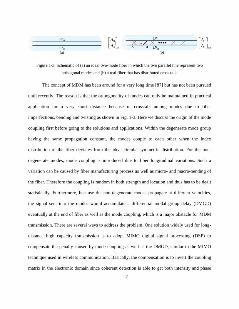
Figure 2-3. The schematic setup for LP11 crosstalk measurement
In order to measure LP11 crosstalk, both excitation and reception were conducted in free-
space using phase plates shown in Fig. 2-3. For excitation, light was launched from a SMF into
free space and through a phase plate, which has a π phase difference between two semicircles
and hence filters out most of the LP01 mode. The extinction ratio of the phase plate is estimated
to be about 20dB at 1550nm. For reception, another phase plate was used to convert LP11 mode
into LP01 so that it can be captured by the receiving SMF and at the same time reject residual
LP01 mode in the FMMCF if there is any. The free-space excitation at the input FMMCF facet is
not a perfect LP11 field and thus introduces a discrete crosstalk, which is named excitation-
induced crosstalk in this letter. This imperfection is caused by lack of intensity modulation, the
simple structure of the phase plate and free-space propagation. To simulate this effect, the real
field at the input FMMCF facet is calculated by using the following equation:
2 2 2 1 1 1 1 1( , ) { ( , ) { ( , ) ( , ) { ( , )}}}o o o i i iE x y FT A x y Fresnel P x y A x y FT E x y ( 2-3 )
where ( , )i i iE x y represents the field of the fundamental mode output from an SMF, 1 1 1( , )A x y and
2 2 2( , )A x y denote the aperture functions of the first and second 20x microscope objective lens,
SMF
P.P.
CCD
B.S.
SMF
P.P. 1km FM-MCF
Free-space excitation Free-space reception
0 π 0 π

17
respectively, 1 1( , )P x y refers to the phase structure of the phase plate, the symbol FT and
Fresnel represent Fourier transform and Fresnel diffraction operation. The inset in Fig. 2-4
shows the calculated intensity pattern at the input FMMCF facet, which contains two tails
instead of a clean LP11 mode. The excitation-induced crosstalk value varies with the angle with
respect to the axis of the phase plate. The excitation is maximum (minimum) for a neighboring
core that is placed perpendicular (parallel) to the line dividing the two phases on the phase plate.
The maximum excitation-induced crosstalk can be obtained by evaluating the overlap integral
between the field at the FMMCF input facet and LP01 and LP11 mode profiles of the FMMCF.
Figure 2-4 shows that the induced crosstalk also depends on the propagation distance from the
phase plate to the FMMCF. Experimental results agree with this trend when the distance between
the phase plate and the input FMMCF facet is shorter than 0.5 m, when the crosstalk reaches a
floor of about -40dB for 1km fiber. The reason might be the simulation does not take account of
leaky LP21 / LP02 modes and cladding modes within the FMMCF. Initially, the measured
11LPXT only after a short piece of 2m fiber and of 1 km fiber were observed to be the same at
around -40dB [103]. As a result, it was concluded that crosstalk floor was due to the
measurement setup.

18
Figure 2-4. Simulated 11LP free-space excitation-induced crosstalk value as a function of the propagation
distance from phase plate to the FMMCF as well as the intensity pattern at FMMCF facet
However, we have confirmed recently that the value of -40dB/km is the actual LP11
crosstalk due to the FMMCF itself. This is made possible by adding another step in the 11LPXT
crosstalk measurement in which one turn of tight bend was introduced near the excitation end of
the fiber. The mandrel diameter of the bend is 50mm. This small amount of tight bend effectively
eliminates the leaky LP21 mode and cladding modes caused by imperfect excitation. The
measured 11LPXT after 1km FMMCF with tight bend is still around -40dB while that after 2m
fiber is less than -47dB. These results infer that the detected -40dB 11LPXT is from 1km of
propagation along the fiber. The large discrepancy of 11LPXT between experimental measurement
and simulation is under investigation. It could be contributed by fiber imperfections, such as the
longitudinal variance along the fiber or the hexagonal core shape, which result from the fiber
drawing process. Another possible reason is that the leaky LP21 / LP02 mode can act as an
0.2 0.3 0.4 0.5 0.6 0.7 0.8-60
-50
-40
-30
-20
-10
Distance between phase plate & FMMCF [m]
Ma
xim
um
in
du
ce
d-c
rossta
lk [
dB
]
Intensity pattern at FMMCF facet

19
intermediary and mediate 11LPXT through a considerable intra-core crosstalk with LP11 mode.
For example, during propagation, a fraction of the launched LP11mode may couple into LP21 /
LP02 mode within the same core, and then the LP21 / LP02 mode would leak into the modes of
the other cores, including LP11 modes and be detected as 11LPXT .
2.4 Initial Transmission Experiment
The 1km few-mode MCF has been tested in a single channel transmission experiment for
both 01LP and 11LP respectively. The experimental setup is shown in Fig. 2-5(a) and the fiber was
wound on a fiber drum whose mandrel radius is15.9cm. Light from an external cavity laser at
1550nm is modulated to produce a 10Gsym/s BPSK signal using a pattern generator. Then the
signal is coupled into either the LP01 or LP11 mode of an arbitrary core of the 1km FMMCF.
Each mode is excited and received in free space with objective lenses for better comparison. The
insets in Fig. 2-5(a) show the LP01 and LP11 mode profiles at the transmitter and receiver. It is
observed that both mode profiles are highly preserved through transmission over the 1 km
FMMCF. When LP11 is transmitted, one phase plate is added at the input to excite an almost
pure LP11 mode and another one is inserted at the output to convert the LP11 mode back to the
LP01 mode. The received signal is then sent to a 90 degree hybrid followed by four photo
detectors. The variable attenuator and the following amplifier before the hybrid are used for
noise loading. The received waveforms were recorded using a real-time oscilloscope and
analyzed offline. Fig. 2-5(b) shows the Q2-factors as a function of the optical signal-to-noise
ratio (OSNR) for the LP01 and LP11 modes after transmission as well as for back-to-back

20
measurement. The transmission penalties for the LP01 and LP11 modes are less than 1dB and
2dB, compared to back-to-back, respectively. These penalties could be due to discrete mode
coupling induced by the imperfect excitation. For example, LP11 free-space excitation using a
phase plate cannot completely filter out the LP01 mode. The residual LP01 would transmit
together with LP11 and produce a small amount of modal dispersion-induced penalty in the LP11
transmission experiment.
Figure 2-5. (a) The setup for LP01 and LP11 transmission over 1km FMMCF (b) Q2 factor v.s. OSNR for
back-to-back, LP01 and LP11 transmission.
2.5 Collaborated 200Tb/s Transmission Experiment
A few-mode multi-core fiber consisting of 7 cores each supporting 3 spatial modes per
polarization has been designed and fabricated. Low core-to-core crosstalk levels have been
achieved for both LP01 and LP11 modes. Data transmission in LP01 / LP11 mode over 1km of
FMMCF has been demonstrated. The fiber is able to support petabits transmission for next
generation high capacity communication.
ECL
10GSym/s 1km FMMCF
LO
90o
Hybrid
PD
PD
RTOOffline DSP
P.P.
Free space coupling
P. P.
Free space coupling
10 15 20 256
8
10
12
14
16
18
20
OSNR(dB)
Q2(d
B)
B2B
LP01
LP11
(a) (b)
21
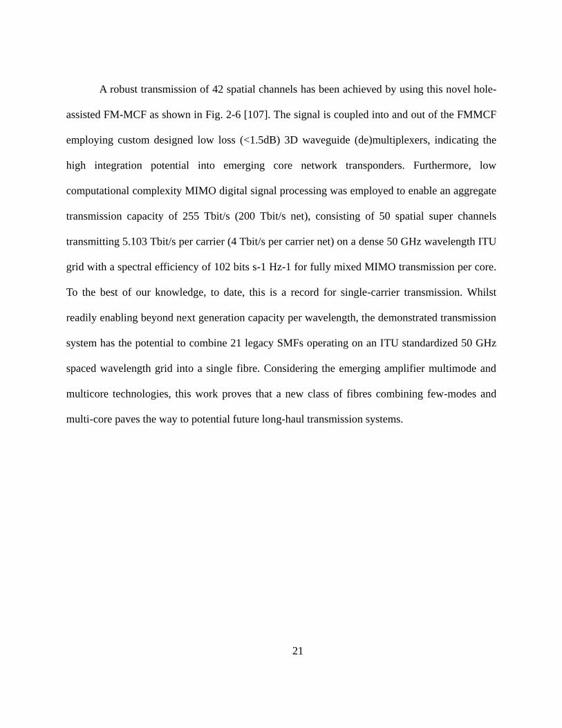
A robust transmission of 42 spatial channels has been achieved by using this novel hole-
assisted FM-MCF as shown in Fig. 2-6 [107]. The signal is coupled into and out of the FMMCF
employing custom designed low loss (<1.5dB) 3D waveguide (de)multiplexers, indicating the
high integration potential into emerging core network transponders. Furthermore, low
computational complexity MIMO digital signal processing was employed to enable an aggregate
transmission capacity of 255 Tbit/s (200 Tbit/s net), consisting of 50 spatial super channels
transmitting 5.103 Tbit/s per carrier (4 Tbit/s per carrier net) on a dense 50 GHz wavelength ITU
grid with a spectral efficiency of 102 bits s-1 Hz-1 for fully mixed MIMO transmission per core.
To the best of our knowledge, to date, this is a record for single-carrier transmission. Whilst
readily enabling beyond next generation capacity per wavelength, the demonstrated transmission
system has the potential to combine 21 legacy SMFs operating on an ITU standardized 50 GHz
spaced wavelength grid into a single fibre. Considering the emerging amplifier multimode and
multicore technologies, this work proves that a new class of fibres combining few-modes and
multi-core paves the way to potential future long-haul transmission systems.

22
Figure 2-6. FMMCF PDM/WDM/SDM transmission experimental setup. (a) the entire experimental setup;
(b) the decorrelated wavelength spectrum after being interleaved by a wavelength selective switch; (c) 3D
waveguide facet; (d) FM-MCF facet which butt-coupled to the 3D waveguide; (e) saturated camera image
taken at the FM-MCF receiver side.
...
Even
Odd
Mu
ltip
lexe
r
Laser 1
Laser 50
ChUT Laser
24
.3G
bau
dTr
ansm
itte
r
EDFA
Load
ing
Ch
ann
els
10 kmLocal Oscillator
Odd/Even Channel Decorrelation
10
0G
Hz
Inte
rlea
ver EDFA
3D waveguideMultiplexer
3D waveguideDemultiplexer
Co
re S
wit
ch
=
21
1km FM-MCF =
21
Co
reSw
itch
PolarizationMultiplexer
44ns
293ns
75ns
185ns
EDFAs
551ns
CoUT
EDFA
1:18Loading Cores
TDM
-SD
MR
ecei
ver
CoUT
(a)
Wavelength [nm]1542.14 1561.81
0R
elat
ive
Tran
s-40
0
mit
ted
Po
wer
[d
B]
Od
dEv
en
-30
-20
-10
40µm 40µm40µm-30
-20
-10
(b) (c) (d) (e)1 2
3 4 5
6 7
23
CHAPTER 3 COUPLED MULTI-CORE FIBERS FOR SDM
TRANSMISSION
3.1 Introduction
Supermodes are eigenmodes of composite structures involving coupled constituent
elements, each of which also supporting guided modes in isolation [108, 109]. As indicated in a
number of studies, such multi-core systems can be effectively analyzed using coupled-mode
theory (CMT) - which is particularly effective when the coupling between neighboring elements
is relatively weak. Over the years, the properties of supermodes in either linear [110] or ring
arrays of coupled waveguides have been analyzed using CMT methods [111-113]. Even in the
simplest possible configuration of two coupled channels, supermodes play an important role
given that their interference is the one responsible for the energy exchange behavior in a
directional coupler.
Quite recently, supermodes have received renewed interest within the context of mode-
division multiplexing (MDM), a new transmission method aimed at overcoming the capacity
limit of single-mode fiber communication systems. Since modes tend to couple during long-
distance fiber transmission, unravelling mode crosstalk using multiple-input-multiple-output
(MIMO) digital signal processing (DSP) is necessary for demultiplexing MDM channels [18]. In
the presence of modal group dispersion, the computational load for MIMO DSP is proportional
to the modal group delay [114, 115]. Interestingly, coupled multi-core fibers can be designed to
have reduced modal group delays and/or larger effective areas in comparison with few-mode
fibers (FMF) [116]. In a recent experiment, the modal delay was also found to depend

24
sublinearly on transmission distance in the presence of strong supermode coupling [117]. It is
thus imperative to study the properties of optical supermodes in a systematic manner.
In this chapter, we introduce the coupled multi-core fiber (CMCF) structure with strong
core-to-core coupling [118]. Coupling between cores can be manipulated to achieve better
transmission properties for coupled modes. Field distribution of a coupled mode can be seen as a
superposition of isolated modes, which is the reason why the coupled modes are also called
supermodes. For this reason, supermodes generally have much larger effective area. Due to the
unique properties of supermodes, CMCFs can support larger mode effective areas and higher
mode densities than the conventional multi-core fiber. In addition, these CMCFs can also have
lower modal dependent loss, mode coupling and differential modal group delay than the few-
mode fiber. These advantages enable this new type of fiber as a potential candidate for
applications of both spatial division multiplexing and single-mode operation.
The content is organized as follows. Section 3.2 focuses on the supermodes in CMCFs
with single-mode cores. Section 3.2.1 introduces the basic properties of supermodes by
analyzing a four-core CMCF structure using the coupled-mode theory. Section 3.2.3
demonstrates CMCF designs for short-distance SDM applications with the primary goal of
achieving low crosstalk between the supermodes. Section 3.2.4 gives CMCF designs for the
long-distance SDM applications where the DMGD has to minimized over the transmission band.
In addition, supermode structures with multimode constituent elements were first introduced in
[119].In section 3.3.1-4, we provide analytical description for higher-order supermodes in
different array configurations, including linear, ring and square array lattices. Finally in section
3.3.5, we present an experimental observation of higher-order supermodes in a 3-core fiber array.

25
3.2 Supermodes in Coupled Single-Mode Core Fibers
3.2.1 Coupled-Mode Theory for Supermodes
In this section, we present the basic supermode analysis of CMCFs. A four-core CMCF
structure, shown in Fig. 3-1, is selected as an example. Fiber cores are assumed to be identical
and each of them supports only one mode. The radius of the cores is r , and the distances between
adjacent cores and non-adjacent cores are 1d and 2d , respectively. The cores and the cladding
have refractive indices of 1n and 2n , respectively. The mode of each isolated core has the same
normalized frequency (V-number) 2 2
1 2
0
2 V r n n
.
Figure 3-1. Schematic of a coupled four-core fiber structure.
According to the coupled-mode analysis [120], the interaction between the modes of the
four individual cores can be described by the following coupled-mode equation
2r
1d
2d

26
,A MA d
jdz
( 3-1 )
where
0 1 2 1
1 0 1 2
1 2 3 4
2 1 0 1
1 2 1 0
[ ] , , ( 1,2,3,4)A M
T
i
c c c
c c cA A A A A i
c c c
c c c
refers to the
complex amplitude of the electrical field of the ith core, 0 is the propagation constant of the
single mode, 1c and 2c are the coupling coefficients between adjacent and non-adjacent cores,
respectively. Since M is Hermitian for a lossless system, it can be diagonalized by a unitary
matrix such that
1 ,Q MQ ( 3-2 )
where is a diagonal matrix,
1
2
3
4
0 0 0
0 0 0,
0 0 0
0 0 0
( 3-3 )
in which ( 1,2,3,4)m m is the propagation constant of the mth supermode supported by the
CMCF. The amplitude matrix for the supermodes is represented as
1 ,B Q A ( 3-4 )
under which the coupled-mode equation (1) reduces to

27
.B d
jdz
( 3-5 )
Under the weakly guiding approximation, a general expression of the coupling coefficient
( 1,2)jc j is given as [121]
2 2 201 2
2 3 2
1 1
( / )1.
( )
j
j
K Wd rn n Uc
n r V K W
( 3-6 )
Where U and W can be found by solving equation 0 1 1 0( ) ( ) ( ) ( ) U K W J U W K W J U and
2 2 2 U W V . The J’s and the K’s are Bessel functions of the first kind and modified Bessel
functions of the second kind. After obtaining the coupling coefficients 1c and 2c , the supermodes
can be solved as eigen-modes. The propagation constant of the supermodes are the eigenvalues,
given by:
1 0 1 2 2 0 2 3 0 2 4 0 1 22 ; ; ; 2 . c c c c c c ( 3-7 )
The second and third supermodes are degenerate, having the same propagation constants. Using
1 21.47, 1.468, 7 , 14 n n r m d m and 1.55 m , the field distributions of each
supermode is calculated and shown in Fig. 3-2.
28
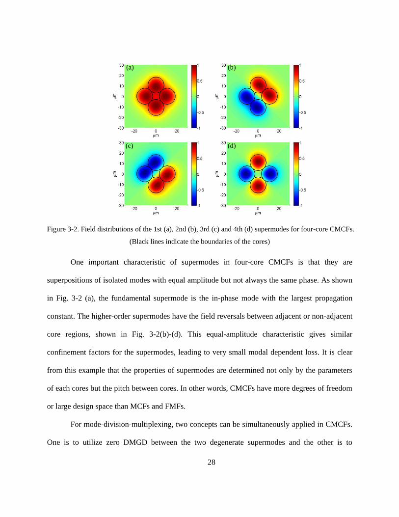
Figure 3-2. Field distributions of the 1st (a), 2nd (b), 3rd (c) and 4th (d) supermodes for four-core CMCFs.
(Black lines indicate the boundaries of the cores)
One important characteristic of supermodes in four-core CMCFs is that they are
superpositions of isolated modes with equal amplitude but not always the same phase. As shown
in Fig. 3-2 (a), the fundamental supermode is the in-phase mode with the largest propagation
constant. The higher-order supermodes have the field reversals between adjacent or non-adjacent
core regions, shown in Fig. 3-2(b)-(d). This equal-amplitude characteristic gives similar
confinement factors for the supermodes, leading to very small modal dependent loss. It is clear
from this example that the properties of supermodes are determined not only by the parameters
of each cores but the pitch between cores. In other words, CMCFs have more degrees of freedom
or large design space than MCFs and FMFs.
For mode-division-multiplexing, two concepts can be simultaneously applied in CMCFs.
One is to utilize zero DMGD between the two degenerate supermodes and the other is to
(a)
(c) (d)
(b)
29
eliminate mode coupling between the non-degenerate supermodes. Demultiplexing can be
realized by first detecting the non-degenerate ones separately and then recover signals mixed in
the degenerate supermodes by MIMO DSP techniques. Compared to FMF modes, the
supermodes can maintain less mode coupling, nonlinearity and similar loss. Considering the
accumulated mode coupling level after long distance can be big, this scheme is best for short-
distance applications which is discussed in the section 3.2.2. The other possibility is to design
CMCFs with zero DMGD (or DMGD much less than the symbol period), between all the
supermodes and a DMGD slope small enough for WDM system. This scheme can be applied to
long-distance applications which we would talk in the section 3.2.3. In that section, a 60 ps/km
DMGD between any two supermodes across the C-band has been demonstrated in a step-index
three-core CMCF. This DMGD value can be further reduced by reducing the index difference
between the core and cladding. It has been reported that graded-index profiles can decrease
DMGD in FMFs [122]. It is likely that a more sophisticated index profile including the graded-
index profile for CMCFs may further reduce the DMGD.
3.2.2 Design for Short-Distance Applications
It is expected that space-division-multiplexed (SDM) optical transmission can operate
successfully either without mode coupling [21] or with mode coupling but with negligible or
small differential modal group delay (DMGD) [18]. For the case that there is no mode coupling,
modes propagate independently and therefore can be separately detected. For the case with mode
coupling but small DMGD , modes may couple to each other, but they can be detected together

30
and then separated by using multiple-input-multiple-output (MIMO) based digital signal
processing (DSP) technique [18]. These two methods can be combined in supermode
multiplexing as will be explained below.
In this simulation, the number of mode is selected to be 6 again. However, the core
arrangement is without a center core so higher-order supermodes and the fundamental
supermode are more symmetrical. The field distributions of the supermodes are shown in Fig. 3-
3. Again, both six-core CMCFs and six-mode fibers support six modes including two pair of
degenerate modes and two other non-degenerate modes. For six-mode fibers, the two pairs of
degenerate modes are the degenerate LP11 and LP21 modes. For CMCFs, the two pairs of
degenerate modes are the 2rd and 3rd, 4th and 5th supermodes. The degenerate supermodes have
identical effective indexes and thus there is no DMGD between them. The non-degenerate
supermodes have different effective indexes. Fortunately, these non-degenerate
supermodes/supermode groups can be designed to have low crosstalk by maintaining a large
effN between them. Therefore demultiplexing in SDM using CMCFs can be successfully
performed in two steps: i) the non-degenerate supermodes/supermode groups are separately
detected while the degenerate supermodes are still mixed together; ii) mixed signals in the
degenerate supermodes are recovered by the MIMO-based DSP techniques [18].

31
Figure 3-3. Field distributions of the 1st (a), 2nd (b), 3rd (c), 4th (d), 5th (e) and 6th (f) supermodes for
the six-core CMCF. (Black lines indicate the boundaries of the cores)
There are three design goals to optimize the performance for SDM: (1) effN between
any two modes should be sufficiently large to avoid mode coupling; (2) mode losses need to be
similar to each other and as low as possible; (3) large effective areas are always required for
reducing nonlinearity. Based on these goals, 6-core CMCFs and 6-mode fibers are designed
respectively and their performances are shown in Fig. 3-4(a) and (b). The macro-bending losses
of the fundamental modes for both fibers are fixed at 0.0308 dB/m at a mandrel radius of 20mm.
Confinement factor is used here to characterize the mode loss. Higher confinement factor implies
lower loss as it indicates less bending loss. From Fig. 3-4(a) and (b), one can see that CMCFs
show a significant advantage of attaining large and similar effN , confinement and effA for all
supermodes. In other words, the supermodes tend to preserve less mode coupling, lower loss and
lower nonlinearity than regular modes. All supermodes have similar properties (including mode
coupling, loss and nonlinearity), which is crucial for long-distance mode-division-multiplexing.
(c)(b)(a)
(d) (e) (f)
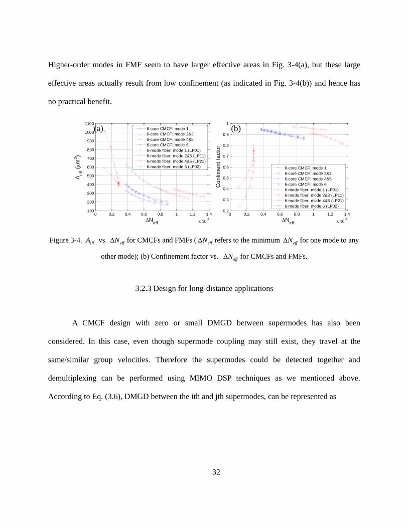
32
Higher-order modes in FMF seem to have larger effective areas in Fig. 3-4(a), but these large
effective areas actually result from low confinement (as indicated in Fig. 3-4(b)) and hence has
no practical benefit.
Figure 3-4. effA vs. effN for CMCFs and FMFs ( effN refers to the minimum effN for one mode to any
other mode); (b) Confinement factor vs. effN for CMCFs and FMFs.
3.2.3 Design for long-distance applications
A CMCF design with zero or small DMGD between supermodes has also been
considered. In this case, even though supermode coupling may still exist, they travel at the
same/similar group velocities. Therefore the supermodes could be detected together and
demultiplexing can be performed using MIMO DSP techniques as we mentioned above.
According to Eq. (3.6), DMGD between the ith and jth supermodes, can be represented as
0 0.2 0.4 0.6 0.8 1 1.2 1.4
x 10-3
100
200
300
400
500
600
700
800
900
1000
1100
Neff
Ae
ff (m
2)
6-core CMCF: mode 1
6-core CMCF: mode 2&3
6-core CMCF: mode 4&5
6-core CMCF: mode 6
6-mode fiber: mode 1 (LP01)
6-mode fiber: mode 2&3 (LP11)
6-mode fiber: mode 4&5 (LP21)
6-mode fiber: mode 6 (LP02)
0 0.2 0.4 0.6 0.8 1 1.2 1.4
x 10-3
0.2
0.3
0.4
0.5
0.6
0.7
0.8
0.9
1
Neff
Co
nfim
ent
fact
or
6-core CMCF: mode 1
6-core CMCF: mode 2&3
6-core CMCF: mode 4&5
6-core CMCF: mode 6
6-mode fiber: mode 1 (LP01)
6-mode fiber: mode 2&3 (LP11)
6-mode fiber: mode 4&5 (LP21)
6-mode fiber: mode 6 (LP02)
(a) (b)
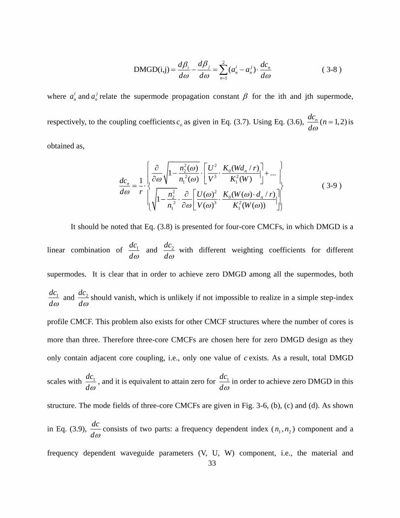
33
2
1
DMGD(i,j) ( )
j i ji n
n n
n
dd dca a
d d d
( 3-8 )
where i
na andj
na relate the supermode propagation constant for the ith and jth supermode,
respectively, to the coupling coefficients nc as given in Eq. (3.7). Using Eq. (3.6), ( 1,2)ndcn
dis
obtained as,
2 2
2 0
2 3 2
1 1
2 2
2 0
2 3 2
1 1
( ) ( / )1 ...
( ) ( )1
( ) ( ( ) / )1
( ) ( ( ))
n
n
n
n U K Wd r
n V K Wdc
d r n U K W d r
n V K W
( 3-9 )
It should be noted that Eq. (3.8) is presented for four-core CMCFs, in which DMGD is a
linear combination of 1dc
d and 2dc
dwith different weighting coefficients for different
supermodes. It is clear that in order to achieve zero DMGD among all the supermodes, both
1dc
d and 2dc
dshould vanish, which is unlikely if not impossible to realize in a simple step-index
profile CMCF. This problem also exists for other CMCF structures where the number of cores is
more than three. Therefore three-core CMCFs are chosen here for zero DMGD design as they
only contain adjacent core coupling, i.e., only one value of c exists. As a result, total DMGD
scales with 1dc
d, and it is equivalent to attain zero for 1dc
din order to achieve zero DMGD in this
structure. The mode fields of three-core CMCFs are given in Fig. 3-6, (b), (c) and (d). As shown
in Eq. (3.9), dc
dconsists of two parts: a frequency dependent index ( 1n , 2n ) component and a
frequency dependent waveguide parameters (V, U, W) component, i.e., the material and
34
waveguide DMGD. At the first glance, one might think that material DMGD is larger than
waveguide DMGD (material dispersion is dominant in chromatic dispersion of standard SMFs).
However, it is incorrect to draw an analogy between DMGD and chromatic dispersion because
the nature of DMGD is differential modal group delay (DMGD) between modes instead of
dispersion within one mode. In fact, all supermodes propagate in the same material but with
different propagation constants, implies that the material DMGD should be negligible compared
to waveguide DMGD. This conclusion is verified by simulation. Since material DMGD is
significantly smaller than waveguide DMGD, they will be neglected in the following discussion
to simplify the analysis.
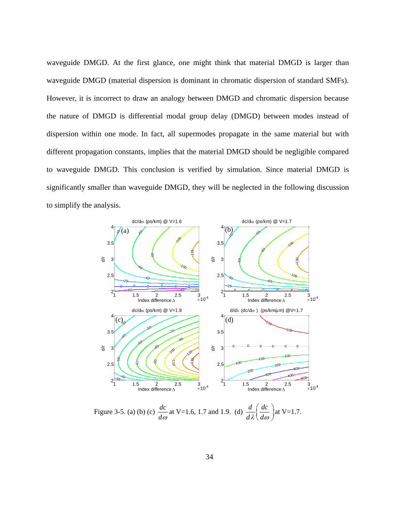
Figure 3-5. (a) (b) (c) dc
dat V=1.6, 1.7 and 1.9. (d)
d dc
d d
at V=1.7.
Index difference
d/r
dc/d (ps/km) @ V=1.6
0 0 0 0 0 0
-20
20 40
-40
-40
-60
-60
-80
-100
-100
-120
1 1.5 2 2.5 32
2.5
3
3.5
4
10-4Index difference
d/r
dc/d (ps/km) @ V=1.7
0 0 0 0 0 0
-20
-40
-40
-60
-60
-60
-80
-100
-100
-120
1 1.5 2 2.5 32
2.5
3
3.5
4
10-4
Index difference
d/r
dc/d (ps/km) @ V=1.9
-30-40
-30
-40
-50
-50
-60
-70
-70
-80
-90
-90
-100
-110
-120
-130
1 1.5 2 2.5 32
2.5
3
3.5
4
10-4Index difference
d/r
d/d (dc/d ) (ps/km/m) @V=1.7
0 0 0 0 0 0
-100
-100
100100
100
200
200
300
300
400500
1 1.5 2 2.5 32
2.5
3
3.5
4
10-4
(a)
(c) (d)
(b)

35
As indicated in Eq. (3.9), dc
dis determined by the pitch-to-core ratio (d/r), V number and
core radius r (or equivalently, V number and index difference ∆ since2 2
1 2
0
2 V r n n
). Their
relationship is shown in Fig. 3-5(a), (b) and (c). It is confirmed by both analysis and simulation
that when the V-number is fixed, zero DMGD is attained if and only if d/r reaches a certain value.
As the V-number increases, zero DMGD is realized for a smaller value of d/r, as indicated in Fig.
3-5(a), (b) and (c). So in order to attain zero DMGD, V-number is limited to below 1.71 because
d/r cannot less than 2. This is demonstrated by the zero DMGD horizontal lines and their
locations with different V-numbers in Fig. 3-5(a), (b) and (c) [in Fig. 3-5(c), with V-
number >1.71, the zero DMGD line does not exist]. Apart from zero DMGD, a sufficiently small
DMGD is enough for practical use as well. This can be obtained by reducing index difference ∆.
To meet the practical application requirements in a WDM system, CMCFs further require
small DMGD variation within a certain range of wavelength, i.e., a small differential modal
group delay slope (DMGDS). (DMGDS can be regarded as linear within a narrow range of
wavelength). Similar to DMGD, DMGDS between the ith and jth supermodes in a three-core
structure can be represented as
11 1(i,j) ( )
jii j
dd d d dcDMGDS a a
d d d d d
( 3-10 )
Given that material DMGD is negligible, the
d dc
d d term can be further expressed as

36
2 2 2
2 0
2 3 2
1 1
1 ( ) ( ( ) / )1
( ) ( ( ))
d dC n U K W d r
d d r n V K W
( 3-11 )
In Fig. 3-5(d), DMGDS is plotted vs. (d/r) and ∆. Even though zero DMGDS can be
realized, they occur at a larger value of d/r with respect to zero DMGD. Therefore, it will be
difficult to achieve zero DMGD and DMGDS simultaneously. Even so, DMGDS can still be
reduced by decreasing index difference ∆. Wavelength-dependent DMGD as well as mode fields
of a specific three-core CMCF design is given in Fig. 3-6 (a) and (b). The DMGD is below 60
ps/km over the entire C band, which is the same value achieved by three-mode fiber using a
depressed cladding index profile [18].
Figure 3-6. (a) maximum DMGD vs. wavelength at V=1.707 @1.55μm and ∆=0.06%, (b) (c) (d) field
distribution of the 1st, 2nd and 3rd supermode of a three-core CMCF
1.5 1.52 1.54 1.56 1.58 1.6-200
-100
0
100
200
Wavelength (m)
Mo
da
l D
isp
ers
ion (
ps/k
m)
C-band
Index difference =0.06%[email protected]

37
3.3 Higher-Order Supermodes in Coupled Few-Mode Core Fibers
When the guiding power is increased for an isolated core, it can guide high-order modes.
For optical fibers with low refractive index contrast, the vector modes are weakly guided and
therefore can be treated as linear polarization (LP) modes. In essence, the LP modes are scalar
approximations of the vector mode fields and contain only one transverse field component given
by,
( )cos( ), for
( )( , )
( )cos( ), for
( )
p pq
p pq
pq
p pq
p pq
J rU p r a
J aE r
K rU p r a
K a
( 3-12 )
where U is the complex amplitude, J and K are Bessel functions of the first and
second kind, a is the core radius, is an arbitrary start angle, and p is a non-negative integer
referred to as the azimuthal mode order. For the same p value, pq and pq can take on
multiple discrete values determined from the dispersion relation. Therefore it is appropriate to
label each of the aforementioned terms with another non-negative integer corresponding to the
number of times the field crosses zero along the radial direction. Thus, the LP modes can be
labeled as pqLP . The orthogonal field component is the same as Eq. (3-12) therefore the results
presented here applies to either polarization. According to Eq. (3-12), when 0p , the modal
field has an additional degree of freedom in the azimuthal direction because the start angle is
arbitrary, which generates spatially orthogonal modes even if both p and q are the same. For
example the 11xLP and 11yLP modes correspond to the cases of 0 and respectively, shown

38
in Fig. 3-7. This is very different from the case of 0p where the 0qLP modal field is
azimuthally uniform and has no spatial degeneracy.
To the best of our knowledge, until now the study of supermodes has been limited to the
supermodes composed of these azimuthally uniform pqLP ( p =0) “core modes”, particularly 01LP
supermodes. However, the higher-order pqLP ( p >0) “core modes” can also form supermodes.
Moreover, these supermodes are strongly affected by the geometrical distribution of the cores
within the MCF, because the coupling of pqLP ( p >0) modes between two cores varies
significantly with initial angles of the modes. We name these angle-dependent supermodes as
“higher-order supermodes.” Unlike the higher-order core modes ( p or q >0), higher-order
supermodes specifically refer to the supermodes formed because of coupling among “core modes”
with p >0. In this section, we begin the study of higher-order supermodes from the simplest two-
core structure by demonstrating how angle-dependent coupling influences the eigenmode
formation. Then, we extend the theory to more complex geometrical structures, using
symmetries to produce analytical formulas for higher-order supermodes. More specifically, we
derive formulas for commonly used formations, including linear-array, grid-array and ring-array
structures.

39
3.3.1 Higher-Order Supermodes in a Two-Core Structure
As described above, the coupling between two pqLP ( p >0) modes strongly depends on
the initial angles of both modes. In order to focus on this angular dependence, the pqLP ( p >0)
modal field of Eq. (3-12) is written as a function of the initial angle
( ) cos( )
cos sin
r
x y
E F p
E E
( 3-13)
where rF represents the radial component of the modal field, ( 0)xE E and ( )2
yE E
correspond to the modal fields aligned with the horizontal axis x and vertical axis y. A
coordinate system is selected where the azimuthal reference axis is parallel to the edge of the
graph formed by vertices at the center of the isolated cores as shown in the inset of Fig. 3-7. The
coupling coefficient between two pqLP ( p >0) modal fields with initial angles of 1 and 2 ,
respectively, in the two identical cores 1 and 2 is given by
2 2
1 1 2 2 0 1 1 2 2
2
1 2 1 2 1 2 1 2
( ( ), ( )) ( ) ( ) ( )2
cos cos sin sin cos sin sin cos
CoreB Clad
Core
x y xy yx
E E n n E E dxdy
( 3-14)
where 1, 2,( , )x x xE E , 1, 2,( , )y y yE E , 1, 2,( , )xy x yE E , 1, 2,( , )yx y xE E . The modal
fields are normalized, 0 and are vacuum permittivity and angular frequency, 2Coren and Cladn
are the refractive indices of core 2 and the cladding, respectively. Fig. 3-7 represents the typical
behavior of the coupling coefficient as the initial angles of two LP11 modes change, according to
Eq. (3-14). 0x y is observed as a result of the specific geometrical distribution of modal
fields with respect to the cores. More importantly, coupling vanished for two specific initial

40
angles, i.e., 0xy yx , as illustrated in by the arrow in Fig. 3-7. This phenomenon occurs
because the mirror-reversal of two modal fields across an axis parallel to the reference axis
should have the same coupling coefficient, which can be mathematically elaborated as
2 2
0 1, 1 2, 2
2
2 2
0 1, 1 2, 2
2
( ) cos( ) sin( )2
( ) cos( ) sin( )2
0
xy CoreB Clad r r
Core
CoreB Clad r r
Core
yx
n n F F dxdy
n n F F dxdy
( 3-15 )
With this result, Eq. (3-14) can be immediately simplified as
1 1 2 2 1 2 1 2( ( ), ( )) cos cos sin sin .x yE E ( 3-16 )
Figure 3-7. Coupling between two arbitrarily oriented 11LP degenerate modes as a function of their initial
angles 1 and 2 . The arrow points to the position of zero coupling 1 2( 0, / 2) 0 between the
11xLP and 11yLP modes; the inset shows the coordinate system of the two cores including reference axes
and two initial angles.
Similar to the 01LP supermodes, higher-order supermodes can be investigated using
coupled-mode theory under the assumption of weak coupling. For the simplest case of the two-
0 50 100 150-1
-0.5
0
0.5
1x 10
-3
=0o
=22.5o
=45o
=67.5o
=90o
Co
up
ling
coef
fici
ent κ
(ϕ1,ϕ
2)
Initial angle ϕ1 (degrees)
ϕ2
ϕ2
ϕ2
ϕ2
ϕ2
LP11x LP11y
(0, ) 02
Core 1 Core 2
1 2

41
core structure, the basis set for each core is strategically chosen as the xE and yE pair, even
though it could have been any orthogonal set with an arbitrary initial angle. Then the interactions
between the “core modes” can be described by the following coupled-mode equation in a matrix
form
0,d
idz
U MU ( 3-17 )
where 1, 2, 1, 2,[ ]T
x x y yu u u uU ; ,m xu or ,m yu are the complex amplitude of the
horizontally or vertically aligned modal field of the mth
core after adopting the gauge
transformation 0
, / , /
i z
m x y m x yu U e
in which 0 is the propagation constant of any isolated core
mode pqLP ; and hence is a 4-by-4 coupled matrix
0 0
0 0.
0 0
0 0
x xy
x xy
yx y
yx y
M ( 3-18 )
The standard procedure of solving the coupled-mode equation is to diagonalize the
coupled matrix 1Q MQ = where the eigenvalues give the normalized propagation constants
of the supermodes. The corresponding eigenvectors 1U = Q U describes the supermode field
amplitudes and the row vectors of 1A = Q represents the amplitude coefficients of superposition
of core modes in forming the supermodes. In the supermode basis, the coupled-mode equation
reduces to
0.d
idz
U U ( 3-19 )

42
For this particular coupled-mode equation, one can apply 0xy yx first and then
divide the equation into two reduced ones as follows,
1, 1,
2, 2,
00
0
x xx
x xx
u udi
u udz
( 3-20a )
1, 1,
2, 2,
00.
0
y y y
y y y
u udi
u udz
( 3-20b )
The above equations mean that xE and yE , the horizontally and vertically aligned “core
modes” do not “talk to” each other and their formation of higher-order supermodes can be solved
separately. Eqs. (3-20a) and (3-20b) turn out to be very similar to those for the case of 01LP
supermodes. The amplitude coefficients of the higher-order supermode corresponding to the row
vectors of 1 1
[1,1;1, 1]2
A Q are the same as those for the 01LP supermodes. For higher-
order supermodes composed of xE and yE respectively, as shown in Fig. 3-8, the propagation
constants of the four higher-order supermodes 0 are calculated to be 0 2 x and
0 2 y , respectively.

43
Figure 3-8. Modal fields of 01LP supermodes (a & b) and 11LP supermodes (c-f) of a basic two-core
structure. In-phase supermodes are shown in (a), (c) and (d) while out-of phase supermodes are shown in
(b), (e) and (f).
3.3.2 Higher-Order Supermodes in Linear-Array Structures
A slightly more complex structure is the linear array where the cores are linearly aligned
with each other with equal core-to-core distances as shown in Fig. 3-9. In this case, couplings
between non-adjacent cores are expected to be negligible. Let us start with the 01LP supermodes,
which do not have angular dependence. One could solve the eigen-problem of the coupled-mode
equation as described in the last section and obtain the supermodes. The alternative method is to
find the solutions that satisfy the boundary conditions 0 1 0Nu u [123]. As a result, the
amplitude of the mth
core within any 01LP supermode can be described as
, 1,2,imQ imQ
mA a e b e m N ( 3-21 )
two-core structure (a) (b)
(c) (d) (f)(e)

44
where a and b are coefficients; Q is the common phase acquired by shifting any one lattice due
to the translational symmetry. The boundary conditions applied to both sides of the linear
structure ( 0m and 1m N )
( 1) ( 1)
1
0 0
0
0,
i N Q i N Q
N
i i
A a e b e
A a e b e
( 3-22 )
yield 0a b and , 1,2,1
lQ l N
N
. Therefore the 01LP supermode can be written as
, , , ,sin , , 1,2,1
l m l m l m l m
lmu A u u m l N
N
( 3-23 )
where l corresponds to the order of different supermodes and mu represents the complex
amplitude of the thm “core mode”. For the thl 01LP supermode, comparing the coupled-mode
equation
1 1( ) 0,m m m
di u u udz
( 3-24 )
with the supermode equation
0m l m
di u u
dz ( 3-25 )
where is the coupling coefficient between two adjacent 01LP “core modes”, the propagation
constant of the thl 01LP supermode 0l l can be obtained as
0 2 cos , 1,2 .1
l
ll N
N
( 3-26 )
For higher-order supermodes, because only coupling between adjacent cores is
considered, xE modes would only couple to themselves as would yE modes, according to
0xy yx . Therefore the higher-order supermodes of the linear-array structure can be divided

45
into the xE - and yE -families; each of them can be solved independently using the same relations
as used for the 01LP supermode. The propagation constants are attained as
, 0 2 cos , 1,21
l x x
ll N
N
( 3-27a )
, 0 2 cos , 1,21
l y y
ll N
N
( 3-27b)
respectively. An example of the 11LP supermodes as well as the 01LP supermodes of a 4-core
linear-array structure is shown in Fig. 3-9.
Figure 3-9. Modal fields of 01LP supermodes (a-d) and 11LP supermodes (e-l) of a 4-core linear-array
structure.
(a) (b) (c) (d)
(h)(g)(f)(e)
(i) (j) (k) (l)
…… linear-array structure
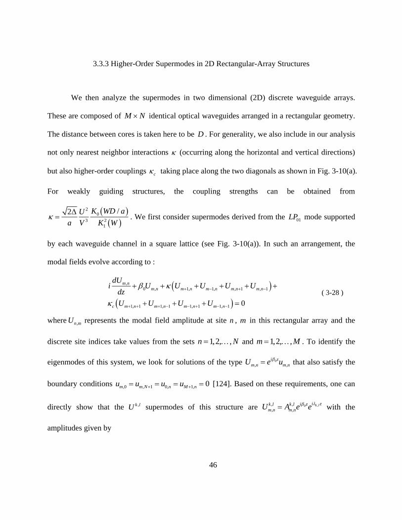
46
3.3.3 Higher-Order Supermodes in 2D Rectangular-Array Structures
We then analyze the supermodes in two dimensional (2D) discrete waveguide arrays.
These are composed of M N identical optical waveguides arranged in a rectangular geometry.
The distance between cores is taken here to be D . For generality, we also include in our analysis
not only nearest neighbor interactions (occurring along the horizontal and vertical directions)
but also higher-order couplings c taking place along the two diagonals as shown in Fig. 3-10(a).
For weakly guiding structures, the coupling strengths can be obtained from
20
3 2
1
/2Δ K WD aU
a V K W . We first consider supermodes derived from the 01LP mode supported
by each waveguide channel in a square lattice (see Fig. 3-10(a)). In such an arrangement, the
modal fields evolve according to :
,
0 , 1, 1, , 1 , 1
1, 1 1, 1 1, 1 1, 1
0
m n
m n m n m n m n m n
c m n m n m n m n
dUi U U U U U
dz
U U U U
( 3-28 )
where , n mU represents the modal field amplitude at site n , m in this rectangular array and the
discrete site indices take values from the sets 1,2, ,n N and 1,2, ,m M . To identify the
eigenmodes of this system, we look for solutions of the type 0
, ,
i z
m n m nU e u
that also satisfy the
boundary conditions ,0 , 1 0, 1, 0m m N n M nu u u u [124]. Based on these requirements, one can
directly show that the ,k lU supermodes of this structure are ,0, ,
, ,k li zi zk l k l
m n m nU eA e
with the
amplitudes given by

47
,
, sin sin1 1
k l
m n
k lA m n
M N
( 3-29 )
where 1,2, ,k M and 1, ,l N . In addition, the eigenvalue associated with ,k lU
supermode is given by
, 2 cos cos 4 cos cos1 1 1 1
k l c
k l k l
M N M N
( 3-30 )
Evidently, altogether this array supports M N supermodes.
Figure 3-10. (a) A rectangular array of waveguides. The 01
LP mode in each waveguide cross-talks with
nearest neighbors along the horizontal and vertical directions as well as with diagonal elements. (b)
Coupling interactions in this same array when each element involves instead the 11
LP mode.
Similarly, one can investigate the eigenmodes of this same array arising from the 11LP
mode of each waveguide (Fig. 3-10(b)). In a weakly coupled array, the 11LP mode tends to orient
itself either along the x or y direction ( 11xLP , 11yLP ). As a result the coupling strengths x and
y are different because of their respective overlap integrals. Hence, the field evolution is
described by

48
,
0 , 1, 1, , 1 , 1
1, 1 1, 1 1, 1 1, 1 0
m n
m n x m n m n y m n m n
c m n m n m n m n
dUi U U U U U
dz
U U U U
( 3-31 )
The supermodes ,k lU of this latter equation are exactly identical in form with those provided by
Eq. (3-29). In this case however, the corresponding eigenvalues are given by
, 2 cos 2 cos 4 cos cos1 1 1 1
k l x y c
k l k l
M N M N
( 3-32 )
In all cases our results (based on coupled-mode theory) are in excellent agreement with finite
element simulations using COMSOL as shown in Fig. 3-11.
Figure 3-11. (a) Scheme of mode basis selection for 11LP supermode analysis of a 4-core grid-array
structure; modal fields of 01LP supermodes (a-d) and 11LP supermodes (e-l) of a 4-core grid-array structure
computed using COMSOL
grid-array structure
(a) (b) (c) (d)
(f) (g) (h)(e)
(j) (k) (l)(i)
………
………
………
………

49
3.3.4 Higher-Order Supermodes in Ring-Array Structures
Ring-array structure is another interesting geometry for higher-order supermodes as it
possesses rotational symmetry. Here also, we only consider coupling between adjacent cores. We
start from 01LP supermodes of N-core ring-array structure. In this case, the coupled matrix M is
a symmetric circulant matrix. If 0 and are defined as the propagation constant of the “core
mode” and the coupling coefficient between two adjacent 01LP “core modes” respectively, the
elements of the N-by-N coupled matrix are given as
0 1, , 1( )lm lm l m l m M ( 3-33 )
where lm , 1,l m and , 1l m are Kronecker deltas; l and m are integer numbers mod N . This
matrix can be diagonalized by a lattice Fourier transform as 1Q MQ [112]. 1Q is a unitary
matrix with elements given as
2
1 1( )
li m
Nlm e
N
Q ( 3-34 )
which represents the amplitude of thm core for the thl 01LP supermode. These discrete helical
phases give supermodes an appearance similar to optical vortices but in a discrete form and thus
carry orbital angular momentum [111]. The propagation constant of the thl 01LP supermode
equals the corresponding eigenvalue and can be calculated as
0
22 cos , 1,2 .l
ll N
N
( 3-35 )
According to Eq. (3.24), it is obvious that the thl and ( )thN l supermodes are degenerate
modes. This has a physical explanation from the equivalence between clockwise and counter-

50
clockwise mode orders. A unitary transformation can project the vortex-like basis of the thl and
( )thN l supermodes into another orthogonal basis. In particular, the degenerate supermodes can
be transformed into a basis in real fields with amplitude transformation as below
, ,
, ,
1 11
1 12
l m l m
N l m N l m
B A
B A
( 3-36 )
where ,
2 2cosl m
lB m
N N
and ,
2 2sinN l m
lB m
N N
.
The higher-order supermodes of ring-array structure are particularly interesting because
they can no longer be divided into xE - and yE -basis for independent analysis. Instead, the
tangential and normal mode basis mt
E and mnE ( m refers to the core number) are selected, which
correspond to “core modes” aligned horizontally or vertically with respect to the reference axis
pointing from the ring center to the thm core. Figure 3-12(a) shows such a mode basis for a 3-
core ring-array structure. In that case, 1,2 2,3 3,1 is obtained because of the rotational
symmetry. In addition, the coupling coefficients between the pqLP modes are real so that
, ,i j j i . Therefore the number of coupling coefficients for the N-core ring-array structure is
reduced from 2N to 4 given by
1 2
2 2
, sin cos ,t t x yN N
( 3-37a )
1 2, sin cos sin cos ,t n x yN N N N
( 3-37b)
1 2, sin cos sin cos ,n t x yN N N N
( 3-37c)

51
1 2
2 2
, cos sin .n n x yN N
( 3-37d)
Then the coupled-mode equation for the N-core ring-array can be written as
0,t t
n n
di
dz
U UM
U U ( 3-38 )
where tU and nU are column vectors of dimension N. the coupled matrixtt tn
nt nn
M MM
M Mis a
rank-2N Hermitian matrix and each sub-matrix is a circulant matrix with elements described as
1 2, 1, , 1 ,tt t t l m l mlm
M ( 3-39a )
1 2 1 2, 1, , , 1,tn t n l m n t l mlm
M ( 3-39b )
1 2 1 2, 1, , , 1,nt n t l m t n l mlm
M ( 3-39c )
1 2, , 1 1, .nn n n l m l mlm
M ( 3-39d )
where lm , 1,l m and , 1l m are the Kronecker deltas; l and m are integer numbers mod N.
Diagonalization of the coupled matrix M is the key to solving the higher-order supermodes. It
takes two steps as follows as described in appendix A.
Both the eigenvalues and eigenvectors can be obtained after successful diagonalization of
the coupled matrix. After plugging the coupling coefficients into the eigenvalues and
eigenvectors using Eq. (3.22), the higher-order supermodes can be divided into groups and
solved as
2 2
( )
1 1( )
2 2
1 1
2, if sin 0
2 or , if sin 0
m m
m m
l lN Ni m i mN N
t l n
m m
l l lN Ni m i mN N
t n
m m
le E e E
NE
le E e E
N
( 3-40 )
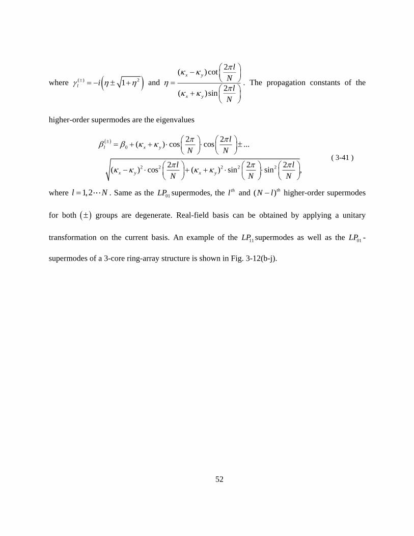
52
where ( ) 21l i and
2( )cot
2( )sin
x y
x y
l
N
l
N
. The propagation constants of the
higher-order supermodes are the eigenvalues
0
2 2 2 2 2
2 2( ) cos cos ...
2 2 2 ( ) cos ( ) sin sin ,
l x y
x y x y
l
N N
l l
N N N
( 3-41 )
where 1,2l N . Same as the 01LP supermodes, the thl and ( )thN l higher-order supermodes
for both groups are degenerate. Real-field basis can be obtained by applying a unitary
transformation on the current basis. An example of the 11LP supermodes as well as the 01LP -
supermodes of a 3-core ring-array structure is shown in Fig. 3-12(b-j).
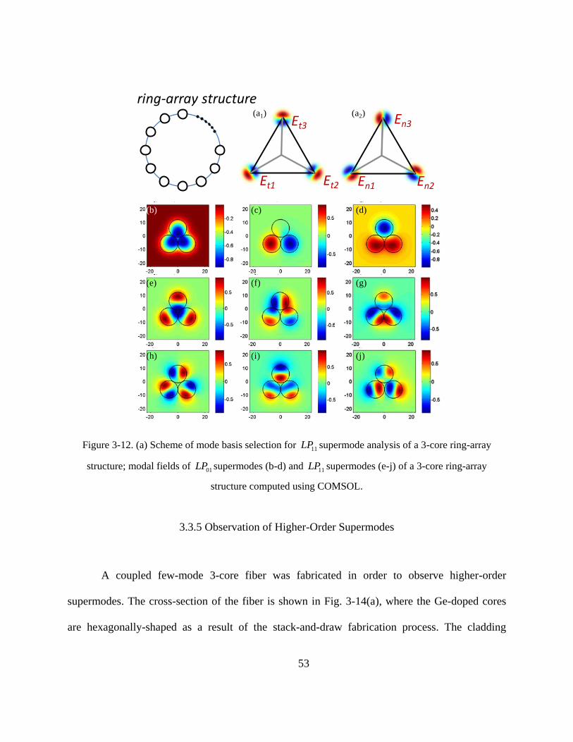
53
Figure 3-12. (a) Scheme of mode basis selection for 11LP supermode analysis of a 3-core ring-array
structure; modal fields of 01LP supermodes (b-d) and 11LP supermodes (e-j) of a 3-core ring-array
structure computed using COMSOL.
3.3.5 Observation of Higher-Order Supermodes
A coupled few-mode 3-core fiber was fabricated in order to observe higher-order
supermodes. The cross-section of the fiber is shown in Fig. 3-14(a), where the Ge-doped cores
are hexagonally-shaped as a result of the stack-and-draw fabrication process. The cladding
ring-array structure
(b) (c) (d)
(g)(f)(e)
(j)(i)(h)
(a1) (a2) En3
En1 En2
Et3
Et1 Et2

54
diameter is ~120μm, and the index difference between the core and cladding is ~0.6%. The core
diameter was selected to be ~9μm to ensure that the cut-off wavelength of the fundamental
modes is well above 1.5μm. In addition, the core pitch was chosen to be ~11.5μm, a small
enough distance to allow for strong coupling. Therefore the fiber supports both 01LP and 11LP
supermodes around 1.5μm.
A spectrally-and-spatially resolved imaging ( 2S imaging) setup was built to acquire the
modal fields from the fiber. The 2S imaging procedure, first developed by J. W. Nicholson et al.
[125], is a technique specially designed for quantifying mode content in fibers. The principle is
to spatially resolve, in a point-by-point fashion, the spectral multi-path interference patterns
produced by mode beatings. The imaging setup can either involve a broadband source
accompanied by a spatial-scanning system or a tunable laser source accompanied by a CCD
camera. For the purposes of this experiment, we chose the latter setup as shown in Fig. 3-13(a)
due to its fast scanning speed and high frequency resolution. Both the tunable laser and the
camera scan in sub-seconds and can be easily synchronized by computer control. In addition, the
tunable laser supports a fine resolution of 0.0001nm with a tuning range of 1510nm-1640nm.
Light coupled from the tunable laser source was launched into approximately 7m of the
fabricated 3-core fiber through free space. The output of the 3-core fiber is imaged onto the
camera through a 4-f optical system. A polarizer was added in front of the camera to guarantee a
single polarization. During the scanning operation, the laser wavelength was incremented in
discrete steps and a mode-interference image was captured by the camera at each step. The
measured 2S results can be expressed as wavelength-interference patterns for every image pixel.
Because modes travel at different group velocities, if three modes are assumed to be excited with

55
amplitudes A , B , C and phase a , b , c , the measured intensity at each pixel location ( , )x y
would be
( , ) ( , ) ( , )0
( , )
2 2 2
( ) | ( , ) ( , ) ( , ) |
( ) 2 cos( ) ...
2 cos( ) 2 cos( ),
a b ab c aci x y i x y i i x y ii
x y
ab ab
ac ac bc bc
I A x y e e B x y e e C x y e e
A B C AB
AC BC
( 3-42 )
where is the angular frequency and ij represents the differential group delay between mode i
and mode j . An example of a measurement at a particular pixel location is plotted as shown in
Fig. 3-13(b). Using that data, one can extract all the mode information by simply applying a
Fourier transform as follows
2 2 2
( , )ˆ( ) ( ) ( ) ( ) ( ) ...
( ) ( ) ( ) ( ) ,
ab ab
ac ac bc bc
i i
x y ab ab
i i i i
ac ac bc bc
I A B C AB e e
AC e e BC e e
( 3-43 )
Fig. 3-13(c) represents the same pixel location after Fourier transform, where every peak
corresponds to each mode beating. Therefore, the amplitude, phase, and group delay of the
modes can be resolved from the peak strength, phase and locations. Using this method, each
mode profile can be extracted from the series of images by performing the Fourier transform on
each pixel as shown in the inset of Fig. 3-13(c).

56
Figure 3-13. (a) Schematic of S2 imaging setup using a tunable laser and a CCD camera; (b) wavelength-
scanning results of the multi-path interference pattern for one pixel of the CCD camera and (c) the result
of intensity vs. differential group delay (DGD) after taking Fourier transform of (b). Inset of (c) shows the
resolved LP modes after picking the information for every pixel at the corresponding DGDs of different
modes and mapping them together.
All the supermodes of the 3-core fiber were obtained using the 2S imaging method. One
difficulty of the experiment is that the mode identification became very complicated due to the
large number of fiber modes. Since every peak is the result of the beating of any two modes, the
number of the mode-beating peaks scales quadratically with the number of modes. In this
experiment, the problem was solved by using intentional offset launching to excite only one
dominant mode with a few other modes for each wavelength sweep. Then, multiple excitations
were required in order to resolve different modes. 2S imaging also suffers from the inherent
inability to separate degenerate modes, which share same group delays. However, due to the
hexagonal shape of the cores in this 3-core fiber, the degenerate modes actually have a subtle
Differential group delay (ps)In
ten
sit
y (d
B)
Wavelength (nm)
Pix
el valu
e
Before F. T. After F. T.
(a)
(b) (c)

57
difference in group delay, making it possible to reconstruct each of them separately. Therefore, a
total of 9 modes supported by the 3-core fiber were successfully reconstructed in both amplitude
and phase, as shown in Fig. 3-14. The first three images are of 01LP supermodes, in which the
field is slightly better resolved than in those of the 11LP supermodes. This is because significantly
less power is coupled into the higher-order modes during center or offset excitation. The
degenerate higher-order mode images are slightly blurry because their group delay difference is
too small to allow them to be clearly differentiated. Nevertheless, the resolved fiber modes are in
good agreement with the simulations shown in Fig. 3-14.

1
Figure 3-14. (a) Cross-sectional view of the fabricated coupled-3-core fiber and (b-j) resolved supermodes
of the fabricated coupled-3-core fiber shown in amplitude (x1) and phase (x2): (b) the fundamental 01LP
supermode; (c, d) the degenerate pair of 01LP supermodes; (d) the fundamental 11LP supermode; (e, f) the
first degenerate pair of 11LP supermodes; (g) the fourth 11LP supermode; (h, i) the second degenerate pair
of 11LP supermodes.
(b2)(a) (b1)
(d2)(d1)(c2)(c1)
(f2)(f1)(e2)(e1)
(h2)(h1)(g2)(g1)
(j2)(j1)(i2)(i1)

2
CHAPTER 4 FEW-MODE PASSIVE OPTICAL NETWORKS
4.1 Introduction and Background
Time-division multiplexed (TDM) passive optical networks (PON) (e.g. GPON and
EPON) are currently being widely deployed worldwide to satisfy the traffic demand in access
networks. There is an increasing interest in PONs towards longer reach and larger splitting ratios
to increase coverage and reduce overall cost. To do so, the power budget needs to be improved
using innovative solutions. In most practical systems, a large power loss is incurred at collector
locations by optical splitters that combine/split signals from/to the optical network units (ONUs).
The downstream power splitting enables the essential one-to-many function from the optical line
terminal (OLT) to ONUs and thus the splitting losses are unavoidable, but the excess upstream
combining loss incurred in one-to-one communication from an ONU to the OLT is neither
necessary nor fundamental and can be reduced in a variety of ways. There has been much effort
aiming to eliminate the upstream combining loss, such as the use of a multi-mode combiner (MC)
[126, 127]. The MC solution, however, requires multiple feeder fibers as shown in Fig. 4-1(a),
which defeats one of the main purposes of fan-out improvement using splitters, that is, the
reduction of the total amount of fibers needed in the network.
Recently, we proposed the use of space-division multiplexing (SDM) in a single few-
mode fiber (FMF), acting as the feeder fiber in the optical distribution network (ODN), to
effectively eliminate the upstream combining loss [128]. Moreover, this concept has been
realized by using a commercial GPON system carrying live Ethernet traffic, achieving the first
reported few-mode GPON [129, 130]. In this paper, we discuss different approaches to achieve

3
TDM few-mode PON, including the previously demonstrated low-crosstalk method and the low
modal group delay (DMGD) method. The experimental setup and results of the few-mode GPON
system are presented in more depth and details. Future work in this area such as mode-division
multiplexing for PON is also discussed.
It should be noted that the application of FMF to access is not simply the transplantation
of a long distance optical transport technique to access. Instead, it focuses on the unique
requirements of optical access. While in optical transport the usual goal is to maximize spectral
efficiency and total information throughput, in access it is most important to maximize the loss
budget and split ratio, and reduce cost per subscriber. While throughput is important, it must be
balanced against other factors. This brings us to different design strategies which leverage better
fiber designs to enable simple direct detection schemes.
Figure 4-1. PON architectures with low upstream loss using (a) multiple feeder fibers and a multimode
combiner (MC); and (b) a single FMF with a mode transforming coupler (MTC).
4.2 Principle of Few-Mode PON
Figure 4-1(b) shows the proposed few-mode PON architecture which consists of a FMF
and a mode-transforming coupler (MTC) in place of a traditional single-mode combiner/splitter
ONU
ONU
ONU
splitter
MTC
splitterFew-mode fiber
……
…… ……
ONU
ONU
ONU
ONU
ONU
ONU
splitter
MC
splitter
SSMF
……
…… ……
ONU
ONU
ONU
SSMF
……
(a)
(b)
OLT
OLT…
ONU
ONU
ONU
splitter
MTC
splitterFew-mode fiber
……
…… ……
ONU
ONU
ONU
ONU
ONU
ONU
splitter
MC
splitter
SSMF
……
…… ……
ONU
ONU
ONU
SSMF
……
(a)
(b)
OLT
OLT…

4
in standard PON systems. The MTC couples multiple single-mode fibers (SMFs) into the FMF.
The MTC can combine signals from feeder fibers with negligible losses [95-97, 131] and thus is
able to increase the fan-out number by a factor equal to the number of the spatial modes,
including the degenerate modes. The critical challenge is from inter-mode crosstalk generated in
the MTC as well as along the FMF, and the modal group delay (DMGD). In long-haul SDM
transmission, inter-mode crosstalk and DMGD are equalized by using sophisticated joint
coherent detection of all the modes, followed by multiple-input-multiple-output (MIMO) signal
processing [88, 132]. For PON applications, coherent detection and MIMO are undesirable due
to their high complexity and cost. Fortunately, one can utilize the unique feature of TDM-PON
that only one ONU is active upstream at any given time and preserve direct detection in the PON
architecture. Given ( )sI t is the only signal transmitted at a time, the detected signal hence can
be written as below
det ,( ) ( ) ( ) ( ) , s i s i j s j i j MGD
i j
I t a I t b I t c I t ( 4-1 )
where the first term is the signal carried by the desired mode while the other terms
represents crosstalk from the other modes generated at different locations. Eq. (4-1) reveals two
different approaches for successful TDM-PON operation. One is to reduce DMGD to be much
less than a symbol period and thus the crosstalk becomes part of the signal. The other approach is
to suppress the modal crosstalk to be low enough that DMGD would no longer be an issue. For
the first approach, one needs to design FMF with very low DMGD or apply the DMGD-
compensation method using FMFs of positive and negative DMGDs [93, 94]. For the second
approach of crosstalk suppression, note that direct detection of all the FMF modes actually
relaxes the requirement for crosstalk as mode crosstalk becomes incoherent in intensity detection
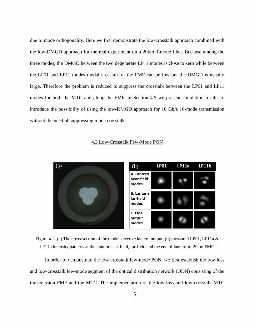
5
due to mode orthogonality. Here we first demonstrate the low-crosstalk approach combined with
the low-DMGD approach for the real experiment on a 20km 3-mode fiber. Because among the
three modes, the DMGD between the two degenerate LP11 modes is close to zero while between
the LP01 and LP11 modes modal crosstalk of the FMF can be low but the DMGD is usually
large. Therefore the problem is reduced to suppress the crosstalk between the LP01 and LP11
modes for both the MTC and along the FMF. In Section 4.5 we present simulation results to
introduce the possibility of using the low-DMGD approach for 10 Gb/s 10-mode transmission
without the need of suppressing mode crosstalk.
4.3 Low-Crosstalk Few-Mode PON
Figure 4-2. (a) The cross-section of the mode-selective lantern output; (b) measured LP01, LP11a &
LP11b intensity patterns at the lantern near-field, far-field and the end of lantern-to-20km FMF.
In order to demonstrate the low-crosstalk few-mode PON, we first establish the low-loss
and low-crosstalk few-mode segment of the optical distribution network (ODN) consisting of the
transmission FMF and the MTC. The implementation of the low-loss and low-crosstalk MTC
20km FMF
Photonic lanternIn
ten
sity
0 2 4 6 8 10
0
0.5
1
Time, ns
Inte
nsity
0 2 4 6 8 10
0
0.5
1
Time, ns
Inte
nsity
0 2 4 6 8 10
0
0.5
1
Time, ns
Inte
nsity
Time, ns
LP01
LP11a
LP11b
(a) (b) (c)(a)

6
can be done in several ways. Generally speaking, all low-loss mode-division multiplexers that
are mode-group selective is suitable for this application, including directional couplers [133],
free-space phase-selective devices [134] and mode-group selective photonic lanterns [95, 131].
Here the MTC is a mode-selective photonic lantern which converts three single-mode inputs
from SSMFs into the LP01, LP11a and LP11b modes of the FMF. The photonic lantern was
fabricated by inserting three input fibers into a fluorine-doped capillary with an index difference
of 4×10⁻³
and then tapering the entire structure adiabatically. Of the three input fibers, two of
them are SMF-28 fibers with propagation constant matched to LP11 modes of the photonic
lantern while the other has a slightly larger core of ~15µm and an index difference of 5×10⁻³
so
that its propagation constant is matched to that of LP01 mode of the photonic lantern to achieve
mode selectivity. The cross-section of the lantern output has a near-triangular core of a diameter
of ~27µm as shown in Fig. 4-2(a). The FMF has a depressed cladding index profile that supports
3 modes, the fundamental LP01 mode and two degenerate LP11 modes, at 1310nm, the upstream
wavelength of GPON. Additionally, the LP11 modes are near cut-off at 1550nm and thus become
very lossy. The attenuations of the LP01 and LP11 modes at 1310nm are 0.33dB/km and
0.35dB/km respectively while at 1550nm the attenuation of the LP11 mode is 0.192dB/km, all
comparable to those of SSMF. The FMF modes are about half sizes of the lantern modes. In
order to reduce the coupling loss due to the mode-size mismatch, a lens combination was used
for free-space lantern-to-FMF coupling. The near-field and far-field output mode intensity
patterns of the photonic lantern and those at the end of the 20km FMF are shown in Fig. 4-2(b),
demonstrating excellent mode selectivity. The insertion loss of the photonic lantern including the
splice loss to the single-mode input fibers was 1.3dB, 0.8dB and 1.4dB for the LP01, LP11a and
7
LP11b mode, respectively, representing an average 3.5 dB improvement in the combining loss
compared to conventional single-mode splitters. The coupling loss from the lantern output to the
FMF, mainly due to mode mismatch between the lantern and the FMF as well as the scattering,
was estimated to be 2.4dB for LP01 and 6.7dB, 6.2dB for LP11a&b. Those coupling losses can
be substantially decreased by using a photonic lantern better matched to the FMF [128]. The
crosstalk of the entire few-mode segment shown in Fig. 4-3(a) was measured by the impulse-
response method. In order to do so, a narrow pulse was sent into each input port of the photonic
lantern, transmitted through 20km FMF and received by a high-speed free-space-coupled photo-
detector. The crosstalk levels were optimized to be less than 9dB for all the three inputs, as
shown in Fig. 4-3(b). The DMGD between the LP01 and LP11 modes was characterized at the
same time to be ~0.6ns over 20km FMF.
Figure 4-3. (a) Picture of the few-mode segment of the ODN; (b) measured LP01, LP11a and LP11b
impulse responses of the few-mode ODN segment.
20km FMF
Photonic lantern
Inte
nsi
ty
0 2 4 6 8 10
0
0.5
1
Time, ns
Inte
nsity
0 2 4 6 8 10
0
0.5
1
Time, ns
Inte
nsity
0 2 4 6 8 10
0
0.5
1
Time, nsIn
tensity
Time, ns
LP01
LP11a
LP11b
(a) (b) (c)
0 2 4 6 8 10
0
0.5
1
Time, ns
Inte
nsity
0 2 4 6 8 10
0
0.5
1
Time, ns
Inte
nsity
0 2 4 6 8 10
0
0.5
1
Time, ns
Inte
nsity
Time, ns
Inte
nsi
ty
LP01
LP11a
LP11b
(b)
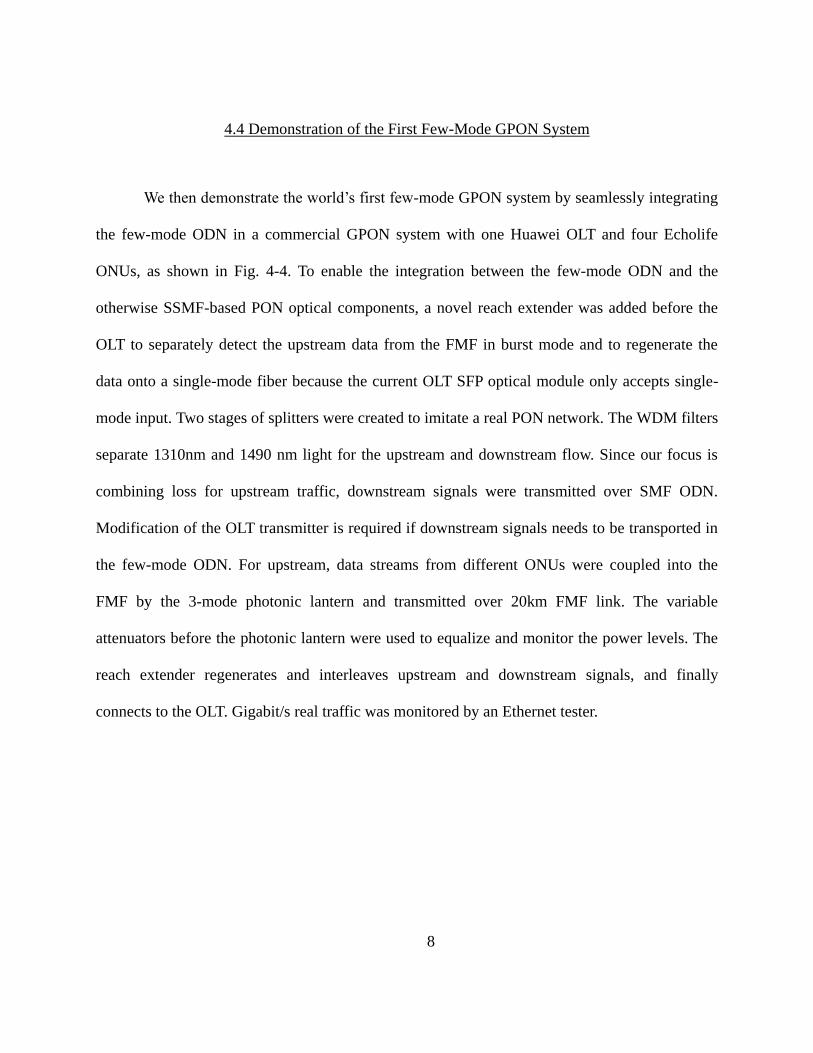
8
4.4 Demonstration of the First Few-Mode GPON System
We then demonstrate the world’s first few-mode GPON system by seamlessly integrating
the few-mode ODN in a commercial GPON system with one Huawei OLT and four Echolife
ONUs, as shown in Fig. 4-4. To enable the integration between the few-mode ODN and the
otherwise SSMF-based PON optical components, a novel reach extender was added before the
OLT to separately detect the upstream data from the FMF in burst mode and to regenerate the
data onto a single-mode fiber because the current OLT SFP optical module only accepts single-
mode input. Two stages of splitters were created to imitate a real PON network. The WDM filters
separate 1310nm and 1490 nm light for the upstream and downstream flow. Since our focus is
combining loss for upstream traffic, downstream signals were transmitted over SMF ODN.
Modification of the OLT transmitter is required if downstream signals needs to be transported in
the few-mode ODN. For upstream, data streams from different ONUs were coupled into the
FMF by the 3-mode photonic lantern and transmitted over 20km FMF link. The variable
attenuators before the photonic lantern were used to equalize and monitor the power levels. The
reach extender regenerates and interleaves upstream and downstream signals, and finally
connects to the OLT. Gigabit/s real traffic was monitored by an Ethernet tester.

9
Figure 4-4. Schematic of a few-mode GPON system using a 20km FMF and a mode-selective lantern for
upstream transmission. OLT: commercial optical line terminal; ONUs: commercial optical network units.
The upstream transport performance through the few-mode ODN was characterized via
bit-error-rate (BER) measurements at 1.25 Gb/s using a 1.3µm DFB laser and an APD ROSA
without limiting amplification and clock data recovery. The transmitter output was switched to
the three photonic lantern input ports one at a time to test each mode. The BER results are
plotted in Fig. 4-5(a). The back-to-back (B2B) receiver sensitivity at a BER of 10-3 is -30 dBm.
The B2B eye diagram and those after 20km transmission for each mode are shown as Fig. 4-5(b).
The eye diagrams of LP01 and B2B cases are almost identical. The LP11s have slightly degraded
performance. Nevertheless, all the modes can achieve a BER of <10-9, which is good enough for
successful commercial GPON operation. Compared to B2B, the LP11a and LP11b modes exhibit
power penalties of 1.5 dB and 2.7 dB, respectively. We attribute these moderate implementation
penalties to imperfect matching between the LP11 modes and the free-space-coupled photo-
detector area, which was matched to SSMF inputs. This penalty is expected to be eliminated
ONU1
ONU2
ONU3
ONU4
OLT20km FMF
20km SSMF
3-mode PLE
the
rne
t teste
r
spli
tter
WDM
filter
WDM
filter
WDM
filter
Configcomputer
PON I/FSys Con WAN I/F
1310nm
1490nm
spli
tterR
each
exte
nd
er

10
using a properly designed photo-detector. The error-free performance of the few-mode ODN
allowed us to carry live Ethernet traffic in the few-mode GPON system using a commercial
Ethernet tester. Long-term measurement was done with no packet loss observed over tens of
millions of Ethernet packets received.
Figure 4-5. (a) BER measurements of the few-mode ODN segment; (b) eye diagrams of the cases of B2B
(with SSMF), 20km LP01, LP11a and LP11b transmission.
4.5 Alternatives and Discussion
Even though the low-crosstalk approach has been demonstrated successfully for three-
mode transmission, crosstalk suppression for both the MTC and the FMF is still difficult in
general, especially when it scales to larger number of modes. On the other hand, the alternative
approach only requires the FMF to have low-DMGD between all the modes. As a result the
requirement for MTC relaxes to be simply low insertion loss, which can be easily achieved [135].
In this section we consider the alternative low-DMGD approach when the number of modes
scale to 10 (i.e., LP01, LP02 and degenerate LP11s/ LP21s/ LP12s/ LP31s modes). Based on
-32 -30 -28 -26 -24 -22 -20-10
-9-8
-7
-6
-5
-4
-3
-2
Received power, dBm
log
(BE
R)
B2B (SSMF)
20km LP01
20km LP11a
20km LP11b
B2B LP01
LP11bLP11a
(a) (b)

11
previous works for fewer modes [91, 136], trench-assisted graded-index profile has been found
to be useful for DMGD optimization and hence will be applied here as well. The inset of Fig. 4-6
shows the graded-index profile, with a cladding trench for low DMGD, given by
1/2
1 1 1
1 2
2 2 3
3
(0) [1 ( / ) ] , ( )
, ( )( )
(1 ), ( )
, ( )
n
cl
cl
cl
n r a r a
n a r an r
n a r a
n r a
( 4-2 )
where n is the power coefficient of the GI profile. With fiber parameters chosen as
1 2 2 1 215.32 , 17.2 , 22.12 , 0.4375% and 0.33% a m a m a m , the differential
modal group delay of a 10-mode GI FMF (referenced to the average modal group delay) at 1310
nm as a function of the power coefficient is shown in Fig. 4-6. The maximum DMGD (between
the fastest and slowest mode) is less than 7 ps/km, achieved near 2.0n . This fiber design
should be able to support few-mode transmission of reach up to 20 km for standard PON (data
rate of 2Gb/s) in presence of mode crosstalk. The high sensitivity of DMGD to the power
coefficient and other fiber parameters should be studied and improved, possibly using different
fiber structures.
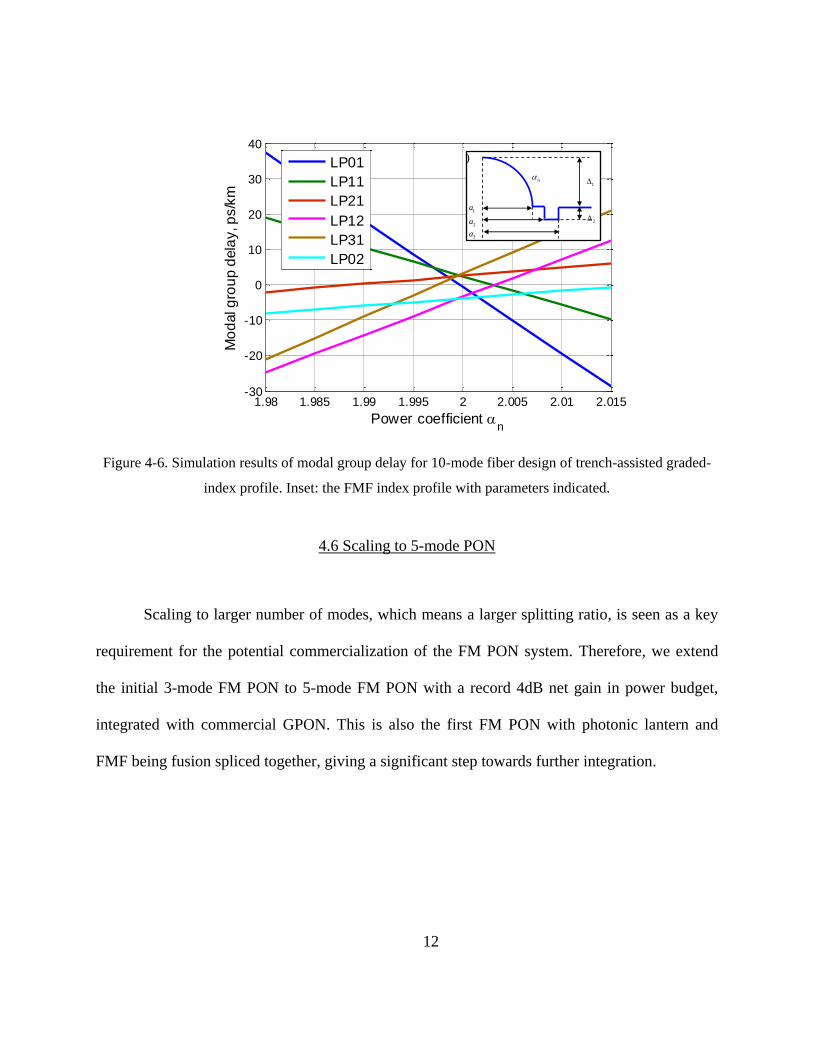
12
Figure 4-6. Simulation results of modal group delay for 10-mode fiber design of trench-assisted graded-
index profile. Inset: the FMF index profile with parameters indicated.
4.6 Scaling to 5-mode PON
Scaling to larger number of modes, which means a larger splitting ratio, is seen as a key
requirement for the potential commercialization of the FM PON system. Therefore, we extend
the initial 3-mode FM PON to 5-mode FM PON with a record 4dB net gain in power budget,
integrated with commercial GPON. This is also the first FM PON with photonic lantern and
FMF being fusion spliced together, giving a significant step towards further integration.
1.98 1.985 1.99 1.995 2 2.005 2.01 2.015-30
-20
-10
0
10
20
30
40
Power coefficient n
Mo
dal g
rou
p d
ela
y, p
s/k
m
LP01
LP11
LP21
LP12
LP31
LP02
1a
2a
3a
12
3
(a)
n
1a
2a
3a
1
2
(b)

13
Figure 4-7. (a) The cross-sectional view of the photonic lantern output. (b) Intensity patterns of 5 modes
for the near-field and far-field output of the photonic lantern and after 20km propagation via the FMF at
1.3μm.
The key to realizing direct detection without any MIMO processing is to either have very
low crosstalk or very small differential group delay between the mode groups [129]. Notice that
within a mode group, modes usually have strong crosstalk in between but the differential group
delay is negligible. Here we choose the low crosstalk approach and hence have a critical
crosstalk requirement for both the photonic lantern and the FMF. The cross-section of the low-
loss mode-selective photonic lantern [137] used for this work is shown in Fig. 4-7(a). In order to
enable the fusion splicing, the photonic lantern was fabricated by inserting different input fibers
into a low-index capillary of a customized size so that it can be adiabatically tapered to the
typical diameter of ~125μm. And each input fiber of the photonic lantern was designed to have a
propagation constant matched to the desired mode and hence achieved good mode selectivity
shown in Fig. 4-7(b). The loss of the photonic lantern itself is < 1dB. The photonic lantern was
fusion spliced to a 20km low-crosstalk FMF to improve both the stability and simplicity of the
setup. The FMF supports up to the LP21 modes at both the upstream and downstream
wavelengths. The index profile of the FMF is shown in Fig. 4-8, allowing large effective index
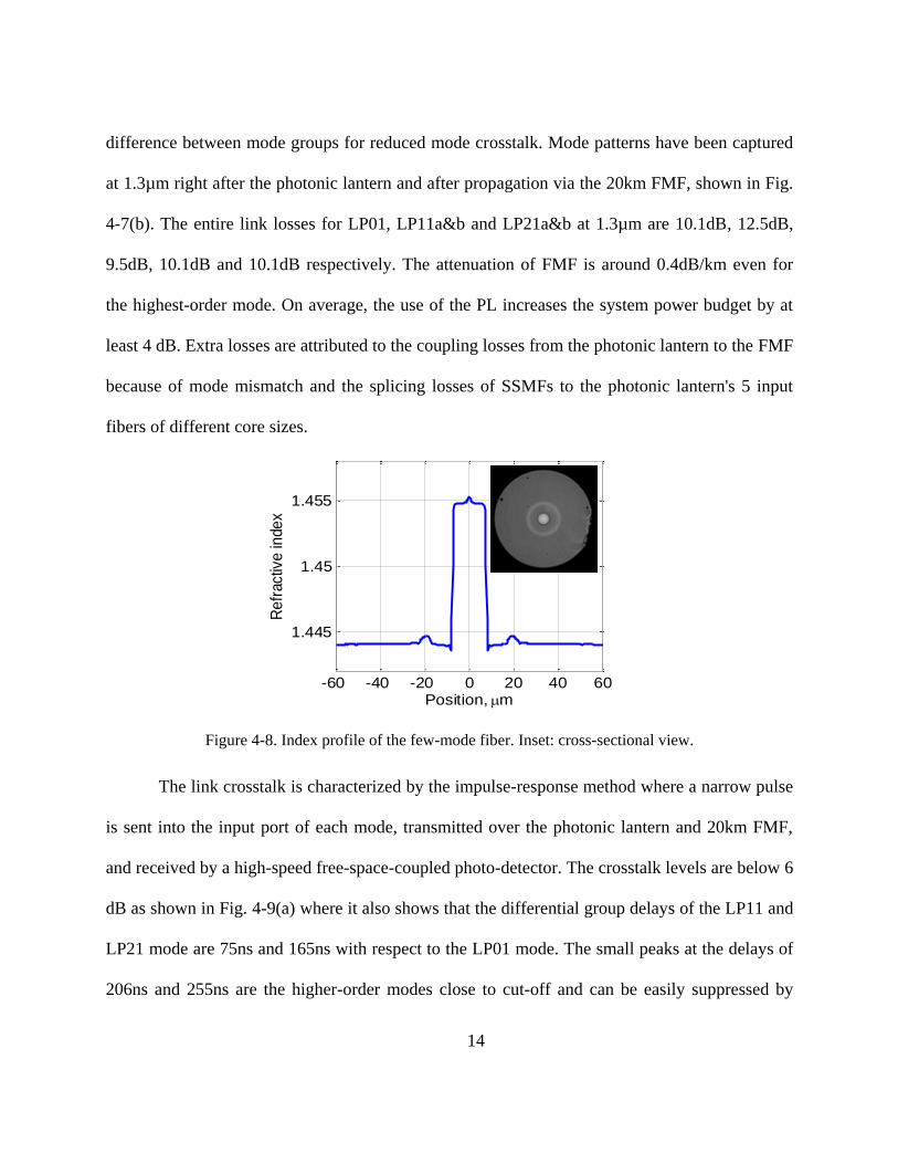
14
difference between mode groups for reduced mode crosstalk. Mode patterns have been captured
at 1.3µm right after the photonic lantern and after propagation via the 20km FMF, shown in Fig.
4-7(b). The entire link losses for LP01, LP11a&b and LP21a&b at 1.3µm are 10.1dB, 12.5dB,
9.5dB, 10.1dB and 10.1dB respectively. The attenuation of FMF is around 0.4dB/km even for
the highest-order mode. On average, the use of the PL increases the system power budget by at
least 4 dB. Extra losses are attributed to the coupling losses from the photonic lantern to the FMF
because of mode mismatch and the splicing losses of SSMFs to the photonic lantern's 5 input
fibers of different core sizes.
Figure 4-8. Index profile of the few-mode fiber. Inset: cross-sectional view.
The link crosstalk is characterized by the impulse-response method where a narrow pulse
is sent into the input port of each mode, transmitted over the photonic lantern and 20km FMF,
and received by a high-speed free-space-coupled photo-detector. The crosstalk levels are below 6
dB as shown in Fig. 4-9(a) where it also shows that the differential group delays of the LP11 and
LP21 mode are 75ns and 165ns with respect to the LP01 mode. The small peaks at the delays of
206ns and 255ns are the higher-order modes close to cut-off and can be easily suppressed by
-60 -40 -20 0 20 40 60
1.445
1.45
1.455
Position, m
Re
fractiv
e in
de
x

15
tight bends. The bit-error-rate (BER) performance, shown in Fig. 4-10, was measured by using a
1.3μm DFB laser and the same free-space-coupled detector without amplification at 1 Gb/s. Eye
diagrams are plotted in Fig. 4-10(b) where crosstalk displays as double eyelids. Because the
direct detection of the orthogonal modes adds the intensity of the different modes incoherently, it
actually eases the crosstalk requirement largely [130]. Therefore, all modes can achieve a BER
of <10-9
. Power penalties compared to back-to-back (B2B) were due to residual mode crosstalk
and imperfect matching between the FMF modes and photo-detector area, which was only
intended for single-mode inputs.
Figure 4-9. Impulse measurements and (b) eye diagrams of the 5-mode optical link composed of the
photonic lantern spliced with 20km FMF spool.
LP01(b) LP11a LP11b LP21a LP21b
0 200 400
0
5
10
15
Time, ns
Inte
nsity
0 200 400
0
5
10
Time, ns0 200 400
0
10
20
30
Time, ns0 200 400
0
5
10
Time, ns0 200 400
0
5
10
15
20
Time, ns
(a) LP01 LP11a LP11b LP21a LP21b

16
Figure 4-10. BER measurements of the 5-mode optical link
The FMF link was integrated into the optical distribution network of a commercial
GPON system as shown in Fig. 4-11. The GPON equipment includes one Huawei optical line
terminal (OLT) and eight Echolife optical networking units (ONUs). Two stages of splitting at
the ONU side were created to emulate a real PON network. Since our focus is to eliminate the
upstream combining loss, downstream transport at 1490nm was separated by WDM filters and
was still transmitted via 20km SSMF and split into ONUs by a traditional single-mode splitter.
For upstream traffic, data streams from commercial ONUs were sent into each input port of the
photonic lantern, converted into different modes and propagated along the FMF for 20km.
Because the commercial OLT SFP optical module only accepts single-mode input, a reach
extender was added to detect signals from the FMF in burst mode and regenerate the data onto a
SSMF before going into the OLT. In addition, the reach extender contains a WDM filter which
interleaves upstream and downstream signals. Packet loss of bidirectional traffic was monitored
using the Ethernet tester. Transmission on all 5 modes without any packet loss was successfully
demonstrated.
-18 -16 -14 -12 -10 -8 -6
-11-10
-9-8-7-6
-5
-4
-3
-2
-1
Received power, dBm
log
(BE
R)
LP01
LP11a
LP11b
LP21a
LP21b
B2B

17
Figure 4-11. Schematic of 5-mode GPON system using the PL spliced to 20km FMF for upstream
transmission with commercial Huawei OLT and ONUs. OLT: optical line terminal; ONU: optical
networking unit; PL: photonic lantern. Red line represents 1490nm downstream transport; blue line stands
for 1310nm downstream transport; and gray line corresponds to: bidirectional transmission.
As a short summary of the section 4.6, we demonstrate the first 5-mode PON which
achieved to save an upstream combining loss of at least 4dB. Link crosstalk as low as <6dB has
been obtained for the 5 modes with a mode-selective lantern fusion spliced to a 20km FMF.
Therefore a BER of <10-9
is realized for all the 5 modes and thus enables integration with
commercial GPON system. High-density FMF technique realized in access networks may open
up the opportunities for future MDM research, development and commercialization.
Splitter
OLT
PL
Co
nfig
com
pu
ter
Sys Con
1310nm
1490nm
RxTx
1 x 2
1 x 2
1 x 2
20km FMF
Ethernet Tester20km SSMF
WAN I/F
PON I/F ONU 1-8
Reach extender
WDM filters
Splitters

18
CHAPTER 5 SUMMARY
This dissertation focuses on two critical requirements of optical fibers for SDM
transmission: 1) high mode density and 2) either low modal crosstalk or low DMGD. Because
SDM system is only beneficial once integrated, the efforts are not only put on the fiber design
and characterization, but also on how to implement such fibers to SDM transmission and
networking.
In Chapter 1, a FMMCF has been designed and fabricated to increase the mode density
for the first time. The fiber consists of 7 cores each supporting 3 spatial modes per polarization.
Low core-to-core crosstalk levels have been achieved for both LP01 and LP11 modes. Data
transmission in LP01 / LP11 mode over 1km of FMMCF has been demonstrated with negligible
penalty. A SDM transmision of 42 spatial channel has been achieved using this novel fiber as a
collaborated work, enabling an aggregate transmission capacity of 255 Tbit/s.
In Chapter 2, we have proposed a coupled multi-core fiber (CMCF) design for SDM
transmission. The new design exploits the coupling between the cores of a conventional multi-
core fiber instead of avoiding it. This design has advantageous over the conventional multi-core
fiber in terms of higher mode density and larger mode effective area. The applications of CMCFs
can be either short-distance transmission with low crosstalk or long-haul transmission with low
DMGD. As an example, a DMGD design of less than 60ps/km throughout the C band has been
achieved for a coupled-3-core fiber.
In addition, we have investigated higher-order supermodes in the latter part of this
chapter, based on the weakly-coupled assumption. The angle-dependent couplings are able to
strongly affect the modal fields of the higher-order supermodes in different waveguide array

19
configurations. Therefore higher-order supermodes have been analyzed for the linear arrays,
square lattices and ring arrays. General solutions of higher-order supermodes in those structures
of arbitrary sizes are provided. In addition, an experimental observation of higher-order
supermodes has been achieved for the first time in a coupled few-mode 3-core fiber. This study
enriches the concept of supermodes in coupled multi-core waveguides, which may have potential
applications not only in MDM systems, but also in other areas related to waveguide optics, such
as optical phased arrays, beam combining and fiber imaging systems.
In Chapter 3, we demonstrate, for the first time, a few-mode PON that utilizes mode
multiplexing to eliminate the combining losses for upstream traffic. Seamless integration
between a few-mode ODN and a commercial GPON system carrying live Ethernet traffic is
achieved without any packet loss. Simulation results also indicated the possibility of using the
alternative low-DMGD approach. The beneficial combination of SDM and PON may open
exciting opportunities for future research, development, and commercialization. As an important
extended work, we then scaled the few-mode PON to 5 modes, which achieved to save an
upstream combining loss of at least 4dB. Link crosstalk as low as <6dB has been obtained for the
5 modes with a mode-selective lantern fusion spliced to a 20km FMF. Therefore error-free
performance has been realized for all the 5 modes and thus enables integration with commercial
GPON system. High-density FMF technique realized in access networks may open up the
opportunities for future MDM research, development and commercialization.

20
APPENDIX:
DERIVATIONS

21
In order to solve the higher-order supermodes for ring-array structure, diagonalization of
the coupled matrix M is the key. It takes two steps as follows. Because each sub-matrix of M
has the similar form as the coupled matrix of 01LP supermodes, the first step is to utilize the
previous solution and diagonalize the sub-matrixes all together. In order to do so, a rank-2N
modal matrix is defined as
,N
N
Q 0P
0 Q ( A-1 )
where N0 is a N-by-N null matrix and 2
1l
i mN
lme
N
Q according to Eq. (3-34). P then
transforms M into a block matrix composed of diagonal sub-matrixes as below
1 1
1
1 1,
tt tntt tn
nt nnnt nn
D DQ M Q Q M QD = P MP
D DQ M Q Q M Q ( A-2 )
where all the diagonal elements can be calculated
1 2,,
22 cos ,tt t tl l
l
N
D ( A-3a )
1 2,,
22 sin ,tn t nl l
li
N
D ( A-3b )
1 2,,
22 sin ,nt t nl l
li
N
D ( A-3c )
1 2,,
22 cos , 1,2 .nn n nl l
ll N
N
D ( A-3d )
D is a block matrix composed of 4 diagonal N-by-N sub-matrixes, which are commutable with
each other. Notice that if 0 0
0tn ntl l l l D D , then
1 20
0,
22 costt t tl l
l
N
D and
1 20
0,
22 cosnn n nl l
l
N
D are eigenvalues already. In addition, a function of a diagonal matrix

22
is still a diagonal matrix, whose elements are the same function of the original matrix elements,
i.e., lm mlf D f D [112]. With these properties, the second step of diagonalization can be
operated on D similar to a simple 2-by-2 matrix of a b
c d
1 .= R DR ( A-4 )
The eigenvalue matrix is solved as
1)
2
1)
2
tt nn R N
N tt nn R
(D + D D 0
0 (D + D D
( A-5 )
and the modal matrix is
,2 2
tt nn R tt nn R
nt nt
D D D D D DR =
D D ( A-6 )
in which 2( ) 4R tt nn tn nt D D D D D when ,
0tn l lD . Therefore the higher-order supermodes
are the row vectors of the matrix 1 1
R P where 1 N
N
Q 0P P
0 Qand
12 ( )
2 ( )
nt R tt nn
nt R tt nn
D D D DR =
D D D D.
23
LIST OF REFERENCES
1. T. Li, "The impact of optical amplifiers on long-distance lightwave telecommunications,"
Proceedings of the IEEE 81, 1568-1579 (1993).
2. G. Li, "Recent advances in coherent optical communication," Adv. Opt. Photon. 1, 279-307
(2009).
3. D. Boivin, M. Bigot-Astruc, M. Travagnin, and P. Sillard, "Weakly-coupled Few-mode
Fibers for Single-mode and Mode-division-multiplexed Transmissions," in Optical Fiber
Communication Conference(Optical Society of America, 2013), p. OTh3K. 6.
4. N. Hanzawa, K. Saitoh, T. Sakamoto, T. Matsui, S. Tomita, and M. Koshiba,
"Demonstration of mode-division multiplexing transmission over 10 km two-mode fiber
with mode coupler," in Optical Fiber Communication Conference and Exposition
(OFC/NFOEC), 2011 and the National Fiber Optic Engineers Conference(2011), pp. 1-3.
5. E. Ip, N. Bai, Y.-K. Huang, E. Mateo, F. Yaman, S. Bickham, H.-Y. Tam, C. Lu, M.-J. Li, S.
Ten, A. P. T. Lau, V. Tse, G.-D. Peng, C. Montero, X. Prieto, and G. Li, "88x3x112-Gb/s
WDM Transmission over 50-km of Three-Mode Fiber with Inline Multimode Fiber
Amplifier," in 37th European Conference and Exposition on Optical
Communications(Optical Society of America, Geneva, 2011), p. Th.13.C.12.
6. E. Ip, N. Bai, Y.-K. Huang, E. Mateo, F. Yaman, M.-J. Li, S. Bickham, S. Ten, Y. Luo, and
G.-D. Peng, "6x6 MIMO transmission over 50+ 25+ 10 km heterogeneous spans of few-
mode fiber with inline erbium-doped fiber amplifier," in Optical Fiber Communication
Conference(Optical Society of America, 2012), p. OTu2C. 4.
7. E. Ip, M.-J. Li, Y.-K. Huang, A. Tanaka, E. Mateo, W. Wood, J. Hu, Y. Yano, and K.
Koreshkov, "146λx6x19-Gbaud wavelength-and mode-division multiplexed transmission
over 10x50-km spans of few-mode fiber with a gain-equalized few-mode EDFA," in Optical
Fiber Communication Conference(Optical Society of America, 2013), p. PDP5A. 2.
8. C. Koebele, M. Salsi, L. Milord, R. Ryf, C. A. Bolle, P. Sillard, S. Bigo, and G. Charlet,
"40km Transmission of Five Mode Division Multiplexed Data Streams at 100Gb/s with low
MIMO-DSP Complexity," in 37th European Conference and Exposition on Optical
Communications(Optical Society of America, Geneva, 2011), p. Th.13.C.13.
9. Y. Li, J. D. Ingham, V. Olle, G. Gorden, R. V. Penty, and I. White, "20 Gb/s Mode-Group-
Division Multiplexing employing Hermite-Gaussian Launches over Worst-Case Multimode
Fiber Links," in Optical Fiber Communication Conference(Optical Society of America, San
Francisco, California, 2014), p. W2A.3.

24
10. S. Matsuo, Y. Sasaki, I. Ishida, K. Takenaga, K. Saitoh, and M. Koshiba, "Recent progress
in multi core and few mode fiber," in Optical Fiber Communication Conference(Optical
Society of America, 2013), p. OM3I. 3.
11. S. Randel, R. Ryf, A. Gnauck, M. A. Mestre, C. Schmidt, R. Essiambre, P. Winzer, R.
Delbue, P. Pupalaikis, and A. Sureka, "Mode-multiplexed 6× 20-GBd QPSK transmission
over 1200-km DGD-compensated few-mode fiber," in National Fiber Optic Engineers
Conference(Optical Society of America, 2012), p. PDP5C. 5.
12. R. Ryf, "Space-division Multiplexed Transmission in Novel Few-mode Fibers," in Frontiers
in Optics(Optical Society of America, 2012), p. FW2D. 1.
13. R. Ryf, N. K. Fontaine, H. Chen, B. Guan, S. Randel, N. Sauer, S. J. B. Yoo, A. Koonen, R.
Delbue, P. Pupalaikis, A. Sureka, R. Shubochkin, Y. Sun, and R. Lingle, "23~Tbit/s
Transmission over 17-km Conventional 50 um Graded-Index Multimode Fiber," in Optical
Fiber Communication Conference: Postdeadline Papers(Optical Society of America, San
Francisco, California, 2014), p. Th5B.1.
14. R. Ryf, N. K. Fontaine, M. A. Mestre, S. Randel, X. Palou, C. Bolle, A. H. Gnauck, S.
Chandrasekhar, X. Liu, and B. Guan, "12 x 12 MIMO transmission over 130-km few-mode
fiber," in Frontiers in Optics(Optical Society of America, 2012), p. FW6C. 4.
15. R. Ryf, M. A. Mestre, S. Randel, X. Palou, A. H. Gnauck, R. Delbue, P. Pupalaikis, A.
Sureka, Y. Sun, and X. Jiang, "Combined SDM and WDM transmission over 700-km Few-
Mode Fiber," in Optical Fiber Communication Conference(Optical Society of America,
2013), p. OW1I. 2.
16. R. Ryf, S. Randel, N. K. Fontaine, M. Montoliu, E. Burrows, S. Chandrasekhar, A. H.
Gnauck, C. Xie, R.-J. Essiambre, and P. Winzer, "32-bit/s/Hz spectral efficiency WDM
transmission over 177-km few-mode fiber," in Optical Fiber Communication
Conference(Optical Society of America, 2013), p. PDP5A. 1.
17. R. Ryf, S. Randel, N. K. Fontaine, X. Palou, E. Burrows, S. Corteselli, S. Chandrasekhar, A.
H. Gnauck, C. Xie, R. J. Essiambre, P. J. Winzer, R. Delbue, P. Pupalaikis, A. Sureka, Y.
Sun, L. Gruner-Nielsen, R. V. Jensen, and R. Lingle, "708-km combined WDM/SDM
transmission over few-mode fiber supporting 12 spatial and polarization modes," in Optical
Communication (ECOC 2013), 39th European Conference and Exhibition on(2013), pp. 1-3.
18. R. Ryf, S. Randel, A. H. Gnauck, C. Bolle, R. Essiambre, P. J. Winzer, D. W. Peckham, A.
McCurdy, and R. Lingle, "Space-division multiplexing over 10 km of three-mode fiber
using coherent 6 x 6 MIMO processing," in Optical Fiber Communication Conference and
Exposition (OFC/NFOEC), 2011 and the National Fiber Optic Engineers Conference(2011),
pp. 1-3.
25
19. R. Ryf, S. Randel, M. A. Mestre, C. Schmidt, A. H. Gnauck, R.-J. Essiambre, P. Winzer, R.
Delbue, P. Pupalaikis, and A. Sureka, "209-km single-span mode-and wavelength-
multiplexed transmission over hybrid few-mode fiber," in European Conference and
Exhibition on Optical Communication(Optical Society of America, 2012), p. Tu. 1. C. 1.
20. M. Salsi, C. Koebele, G. Charlet, and S. Bigo, "Mode division multiplexed transmission
with a weakly-coupled few-mode fiber," in Optical Fiber Communication
Conference(Optical Society of America, 2012), p. OTu2C. 5.
21. M. Salsi, C. Koebele, D. Sperti, P. Tran, P. Brindel, H. Mardoyan, S. Bigo, A. Boutin, F.
Verluise, and P. Sillard, "Transmission at 2x100Gb/s, over two modes of 40km-long
prototype few-mode fiber, using LCOS based mode multiplexer and demultiplexer," in
National Fiber Optic Engineers Conference(Optical Society of America, 2011), p. PDPB9.
22. V. Sleiffer, Y. Jung, B. Inan, H. Chen, R. van Uden, M. Kuschnerov, D. van den Borne, S.
Jansen, V. Veljanovski, and T. Koonen, "Mode-division-multiplexed 3x112-Gb/s DP-QPSK
transmission over 80 km few-mode fiber with inline MM-EDFA and blind DSP," in
European Conference and Exhibition on Optical Communication(Optical Society of
America, 2012), p. Tu. 1. C. 2.
23. B. C. Thomsen, "MIMO enabled 40 Gb/s transmission using mode division multiplexing in
multimode fiber," in Optical Fiber Communication (OFC), collocated National Fiber Optic
Engineers Conference, 2010 Conference on (OFC/NFOEC)(2010), pp. 1-3.
24. R. van Uden, C. Okonkwo, H. Chen, H. de Waardt, and A. Koonen, "6×28GBaud 128-SP-
QAM Transmission over 41.7 km Few-Mode Fiber with a 6×6 MIMO FDE," in Optical
Fiber Communication Conference(Optical Society of America, San Francisco, California,
2014), p. W4J.4.
25. S. Yi, R. Lingle, A. McCurdy, D. Peckham, R. Jensen, and L. Gruner-Nielsen, "Few-mode
fibers for mode-division multiplexing," in Photonics Society Summer Topical Meeting
Series, 2013 IEEE(2013), pp. 80-81.
26. C. Koebele, M. Salsi, D. Sperti, P. Tran, P. Brindel, H. Mardoyan, S. Bigo, A. Boutin, F.
Verluise, and P. Sillard, "Two mode transmission at 2x100Gb/s, over 40km-long prototype
few-mode fiber, using LCOS-based programmable mode multiplexer and demultiplexer,"
Optics express 19, 16593-16600 (2011).
27. A. Li, X. Chen, A. Al Amin, J. Ye, and W. Shieh, "Space-division multiplexed high-speed
superchannel transmission over few-mode fiber," Lightwave Technology, Journal of 30,
3953-3964 (2012).
28. S. Randel, R. Ryf, A. Sierra, P. J. Winzer, A. H. Gnauck, C. A. Bolle, R.-J. Essiambre, D. W.
Peckham, A. McCurdy, and R. Lingle, "6× 56-Gb/s mode-division multiplexed transmission
26
over 33-km few-mode fiber enabled by 6× 6 MIMO equalization," Optics Express 19,
16697-16707 (2011).
29. R. Ryf, M. Mestre, S. Randel, C. Schmidt, A. Gnauck, R. Essiambre, P. Winzer, R. Delbue,
P. Pupalaikis, and A. Sureka, "Mode-Multiplexed Transmission Over a 209-km DGD-
Compensated Hybrid Few-Mode Fiber Span," Photonics Technology Letters, IEEE 24,
1965-1968 (2012).
30. V. Sleiffer, P. Leoni, Y. Jung, J. Surof, M. Kuschnerov, V. Veljanovski, S. U. Alam, D. J.
Richardson, L. Grüner-Nielsen, and Y. Sun, "20x 960-Gb/s Space-division-multiplexed
32QAM transmission over 60 km few-mode fiber," Optics express 22, 749-755 (2014).
31. V. A. J. M. Sleiffer, H. Chen, Y. Jung, P. Leoni, M. Kuschnerov, A. Simperler, H. Fabian, H.
Schuh, F. Kub, D. J. Richardson, S. U. Alam, L. Grüner-Nielsen, Y. Sun, A. M. J. Koonen,
and H. de Waardt, "Field demonstration of mode-division multiplexing upgrade scenarios
on commercial networks," Optics Express 21, 31036-31046 (2013).
32. M. Arikawa, E. Le Taillandier de Gabory, T. Ito, and K. Fukuchi, "Improvement of Signal
Quality after Long-Haul Transmission over Multi-Core Fiber with Adaptive MIMO-FDE
Using Time-Domain Coefficient Selection," in Optical Fiber Communication
Conference(Optical Society of America, San Francisco, California, 2014), p. Th2A.38.
33. Y. Awaji, N. Wada, Y. Toda, and T. Hayashi, "World first mode/spatial division
multiplexing in multi-core fiber using Laguerre-Gaussian mode," in European Conference
and Exposition on Optical Communications(Optical Society of America, 2011), p. We. 10.
P11. 55.
34. S. Chandrasekhar, A. Gnauck, X. Liu, P. Winzer, Y. Pan, E. C. Burrows, B. Zhu, T. Taunay,
M. Fishteyn, and M. Yan, "WDM/SDM Transmission of 10 x 128-Gb/s PDM-QPSK over
2688-km 7-Core Fiber with a per-Fiber Net Aggregate Spectral-Efficiency Distance Product
of 40,320 km. b/s/Hz," in European Conference and Exposition on Optical
Communications(Optical Society of America, 2011), p. Th. 13. C. 14.
35. Q. Dayou, E. Ip, H. Ming-Fang, L. Ming-Jun, and W. Ting, "698.5-Gb/s PDM-2048QAM
transmission over 3km multicore fiber," in Optical Communication (ECOC 2013), 39th
European Conference and Exhibition on(2013), pp. 1-3.
36. A. H. Gnauck, S. Chandrasekhar, X. Liu, S. Randel, S. Corteselli, T. Taunay, B. Zhu, and M.
Fishteyn, "WDM Transmission of 603-Gb/s Superchannels over 845 km of 7-Core Fiber
with 42.2 b/s/Hz Spectral Efficiency," in European Conference and Exhibition on Optical
Communication(Optical Society of America, Amsterdam, 2012), p. Th.2.C.2.
37. K. Igarashi, T. Tsuritani, I. Morita, Y. Tsuchida, K. Maeda, M. Tadakuma, T. Saito, K.
Watanabe, K. Imamura, R. Sugizaki, and M. Suzuki, "1.03-Exabit/skm Super-Nyquist-

27
WDM transmission over 7,326-km seven-core fiber," in Optical Communication (ECOC
2013), 39th European Conference and Exhibition on(2013), pp. 1-3.
38. K. Imamura, H. Inaba, K. Mukasa, and R. Sugizaki, "19-core multi core fiber to realize high
density space division multiplexing transmission," in Photonics Society Summer Topical
Meeting Series, 2012 IEEE(2012), pp. 208-209.
39. T. Kobayashi, H. Takara, A. Sano, T. Mizuno, H. Kawakami, Y. Miyamoto, K. Hiraga, Y.
Abe, H. Ono, M. Wada, Y. Sasaki, I. Ishida, K. Takenaga, S. Matsuo, K. Saitoh, M. Yamada,
H. Masuda, and T. Morioka, "2x344 Tb/s propagation-direction interleaved transmission
over 1500-km MCF enhanced by multicarrier full electric-field digital back-propagation," in
Optical Communication (ECOC 2013), 39th European Conference and Exhibition on(2013),
pp. 1-3.
40. M. Koshiba, "Recent progress in multi-core fibers for ultralarge-capacity transmission," in
OptoeElectronics and Communications Conference (OECC), 2010 15th(2010), pp. 38-39.
41. E. Le Taillandier de Gabory, M. Arikawa, Y. Hashimoto, T. Ito, and K. Fukuchi, "A shared
carrier reception and processing scheme for compensating frequency offset and phase noise
of space-division multiplexed signals over multicore fibers," in Optical Fiber
Communication Conference(Optical Society of America, 2013), p. OM2C. 2.
42. E. Le Taillandier De Gabory, M. Arikawa, T. Ito, and K. Fukuchi, "DWDM transmission of
128Gb/s PM-16QAM signal over 1815km of 7-core MCF using shared carrier reception for
improving the received signal quality," in Optical Communication (ECOC 2013), 39th
European Conference and Exhibition on(2013), pp. 1-3.
43. I. Morita, "Long-distance and high-capacity transmission with multicore fiber," in Photonics
Society Summer Topical Meeting Series, 2013 IEEE(2013), pp. 127-128.
44. K. Mukasa, K. Imamura, Y. Tsuchida, and R. Sugizaki, "Multi-core fibers for large capacity
SDM," in Optical Fiber Communication Conference and Exposition (OFC/NFOEC), 2011
and the National Fiber Optic Engineers Conference(2011), pp. 1-3.
45. K. Nakajima, Y. Goto, T. Matsui, and S. Tomita, "Multi-core fiber technologies for
extremely advanced transmission," in OptoeElectronics and Communications Conference
(OECC), 2011 16th(2011), pp. 248-249.
46. B. J. Puttnam, J.-M. Delgado-Mendinueta, J. Sakaguchi, R. S. Luis, W. Klaus, Y. Awaji, N.
Wada, A. Kanno, and T. Kawanishi, "105Tb/s Transmission System Using Low-cost, MHz
Linewidth DFB Lasers Enabled by Self-Homodyne Coherent Detection and a 19-Core
Fiber," in Optical Fiber Communication Conference(Optical Society of America, 2013), p.
OW1I. 1.

28
47. D. Qian, E. Ip, M.-F. Huang, M.-j. Li, A. Dogariu, S. Zhang, Y. Shao, Y.-K. Huang, Y.
Zhang, X. Cheng, Y. Tian, P. Ji, A. Collier, Y. Geng, J. Linares, C. Montero, V. Moreno, X.
Prieto, and T. Wang, "1.05Pb/s Transmission with 109b/s/Hz Spectral Efficiency using
Hybrid Single- and Few-Mode Cores," in Frontiers in Optics 2012/Laser Science
XXVIII(Optical Society of America, Rochester, New York, 2012), p. FW6C.3.
48. J. Sakaguchi, Y. Awaji, N. Wada, A. Kanno, T. Kawanishi, T. Hayashi, T. Taru, T.
Kobayashi, and M. Watanabe, "109-Tb/s (7x97x172-Gb/s SDM/WDM/PDM) QPSK
transmission through 16.8-km homogeneous multi-core fiber," in Optical Fiber
Communication Conference/National Fiber Optic Engineers Conference 2011(Optical
Society of America, Los Angeles, California, 2011), p. PDPB6.
49. J. Sakaguchi, W. Klaus, B. J. Puttnam, J. M. D. Mendinueta, Y. Awaji, N. Wada, Y.
Tsuchida, K. Maeda, M. Tadakuma, K. Imamura, R. Sugizaki, T. Kobayashi, Y. Tottori, M.
Watanabe, and R. V. Jensen, "19-core MCF transmission system using EDFA with shared
core pumping coupled in free-space optics," in Optical Communication (ECOC 2013), 39th
European Conference and Exhibition on(2013), pp. 1-3.
50. J. Sakaguchi, B. J. Puttnam, W. Klaus, Y. Awaji, N. Wada, A. Kanno, T. Kawanishi, K.
Imamura, H. Inaba, and K. Mukasa, "19-core fiber transmission of 19x100x172-Gb/s SDM-
WDM-PDM-QPSK signals at 305Tb/s," in National Fiber Optic Engineers
Conference(Optical Society of America, 2012), p. PDP5C. 1.
51. J. Sakaguchi, B. J. Puttnam, W. Klaus, J.-M. Delgado-Mendinueta, Y. Awaji, N. Wada, A.
Kanno, and T. Kawanishi, "Large-capacity transmission over a 19-core fiber," in Optical
Fiber Communication Conference(Optical Society of America, 2013), p. OW1I. 3.
52. T. Sakamoto, K. Saitoh, N. Hanzawa, K. Tsujikawa, M. Lin, M. Koshiba, and F. Yamamoto,
"Crosstalk suppressed hole-assisted 6-core fiber with cladding diameter of 125
μm," in Optical Communication (ECOC 2013), 39th European Conference and
Exhibition on(2013), pp. 1-3.
53. Y. Sasaki, K. Takenaga, Y. Arakawa, S. Tanigawa, S. Matsuo, K. Saitoh, and M. Koshiba,
"Large-effective-area uncoupled 10-core fiber with two-pitch layout," in Optical Fiber
Communication Conference(Optical Society of America, 2012), p. OM2D. 4.
54. H. Takahashi, K. Igarashi, and T. Tsuritani, "Long-haul transmission using multicore
fibers," in Optical Fiber Communication Conference(Optical Society of America, San
Francisco, California, 2014), p. Tu2J.2.
55. H. Takara, "Multi-core fiber transmission technologies for Peta b/s per fiber capacity," in
Optical Communication (ECOC 2013), 39th European Conference and Exhibition on(2013),
pp. 1-3.
29
56. H. Takara, "Ultra-large-capacity multi-core fiber transmission technologies," in Photonics
Society Summer Topical Meeting Series, 2013 IEEE(2013), pp. 133-134.
57. H. Uemura, Y. Sasaki, S. Nishimoto, T. Uematsu, K. Takenaga, K. Omichi, R. Goto, S.
Matsuo, and K. Saitoh, "Mode Multiplexer/Demultiplexer Based on a Partially Elongated
Multi-Core Fiber," in Optical Fiber Communication Conference(Optical Society of America,
San Francisco, California, 2014), p. Tu3D.3.
58. B. Zhu, X. Liu, S. Chandrasekhar, T. Taunay, M. Fishteyn, M. Yan, J. M. Fini, E. Monberg,
and F. Dimarcello, "112-Tb/s (7x160x107Gb/s) space-division multiplexed DWDM
transmission over a 76.8-km multicore Fiber," in European Conference and Exposition on
Optical Communications(Optical Society of America, 2011), p. Tu. 5. B. 5.
59. S. Chandrasekhar, A. Gnauck, X. Liu, P. Winzer, Y. Pan, E. Burrows, T. Taunay, B. Zhu, M.
Fishteyn, and M. Yan, "WDM/SDM transmission of 10 x 128-Gb/s PDM-QPSK over 2688-
km 7-core fiber with a per-fiber net aggregate spectral-efficiency distance product of 40,320
km⋅ b/s/Hz," Optics express 20, 706-711 (2012).
60. J. H. Chang, H. G. Choi, and Y. C. Chung, "Achievable capacity improvement by using
multi-level modulation format in trench-assisted multi-core fiber system," Optics Express 21,
14262-14271 (2013).
61. K. Igarashi, K. Takeshima, T. Tsuritani, H. Takahashi, S. Sumita, I. Morita, Y. Tsuchida, M.
Tadakuma, K. Maeda, T. Saito, K. Watanabe, K. Imamura, R. Sugizaki, and M. Suzuki,
"110.9-Tbit/s SDM transmission over 6,370 km using a full C-band seven-core EDFA,"
Optics Express 21, 18053-18060 (2013).
62. K. Igarashi, T. Tsuritani, I. Morita, Y. Tsuchida, K. Maeda, M. Tadakuma, T. Saito, K.
Watanabe, K. Imamura, and R. Sugizaki, "Super-Nyquist-WDM transmission over 7,326-
km seven-core fiber with capacity-distance product of 1.03 Exabit/s· km," Optics express 22,
1220-1228 (2014).
63. S. Matsuo, Y. Sasaki, T. Akamatsu, I. Ishida, K. Takenaga, K. Okuyama, K. Saitoh, and M.
Kosihba, "12-core fiber with one ring structure for extremely large capacity transmission,"
Optics express 20, 28398-28408 (2012).
64. S. Naderi Shahi, and S. Kumar, "A multi-core or multi-fiber WDM system," Optics
Communications 294, 289-293 (2013).
65. J. Sakaguchi, Y. Awaji, N. Wada, A. Kanno, T. Kawanishi, T. Hayashi, T. Taru, T.
Kobayashi, and M. Watanabe, "Space division multiplexed transmission of 109-Tb/s data
signals using homogeneous seven-core fiber," Lightwave Technology, Journal of 30, 658-
665 (2012).

30
66. J. Sakaguchi, B. J. Puttnam, W. Klaus, Y. Awaji, N. Wada, A. Kanno, T. Kawanishi, K.
Imamura, H. Inaba, K. Mukasa, R. Sugizaki, T. Kobayashi, and M. Watanabe, "305 Tb/s
Space Division Multiplexed Transmission Using Homogeneous 19-Core Fiber," Lightwave
Technology, Journal of 31, 554-562 (2013).
67. A. Sano, H. Takara, T. Kobayashi, H. Kawakami, H. Kishikawa, T. Nakagawa, Y.
Miyamoto, Y. Abe, H. Ono, K. Shikama, M. Nagatani, T. Mori, Y. Sasaki, I. Ishida, K.
Takenaga, S. Matsuo, K. Saitoh, M. Koshiba, M. Yamada, H. Masuda, and T. Morioka,
"409-Tb/s + 409-Tb/s crosstalk suppressed bidirectional MCF transmission over 450 km
using propagation-direction interleaving," Optics Express 21, 16777-16783 (2013).
68. H. Takara, H. Ono, Y. Abe, H. Masuda, K. Takenaga, S. Matsuo, H. Kubota, K. Shibahara,
T. Kobayashi, and Y. Miaymoto, "1000-km 7-core fiber transmission of 10 x 96-Gb/s PDM-
16QAM using Raman amplification with 6.5 W per fiber," Optics express 20, 10100-10105
(2012).
69. K. Takenaga, Y. Arakawa, Y. Sasaki, S. Tanigawa, S. Matsuo, K. Saitoh, and M. Koshiba,
"A large effective area multi-core fiber with an optimized cladding thickness," Optics
express 19, B543-B550 (2011).
70. B. Zhu, J. M. Fini, M. F. Yan, X. Liu, S. Chandrasekhar, T. F. Taunay, M. Fishteyn, E. M.
Monberg, and F. V. Dimarcello, "High-capacity space-division-multiplexed DWDM
transmissions using multicore fiber," Lightwave Technology, Journal of 30, 486-492 (2012).
71. B. Zhu, T. Taunay, M. Fishteyn, X. Liu, S. Chandrasekhar, M. Yan, J. Fini, E. Monberg,
and F. Dimarcello, "112-Tb/s space-division multiplexed DWDM transmission with 14-
b/s/Hz aggregate spectral efficiency over a 76.8-km seven-core fiber," Optics Express 19,
16665-16671 (2011).
72. N. Bai, "Mode-division Multiplexed Transmission in Few-mode Fibers," (University of
Central Florida Orlando, Florida, 2013).
73. G. Li, N. Bai, N. Zhao, and C. Xia, "Space-division multiplexing: the next frontier in optical
communication," Adv. Opt. Photon. 6, 413-487 (2014).
74. D. Richardson, J. Fini, and L. Nelson, "Space-division multiplexing in optical fibres,"
Nature Photonics 7, 354-362 (2013).
75. P. J. Winzer, "Optical networking beyond WDM," Photonics Journal, IEEE 4, 647-651
(2012).
76. P. J. Winzer, "Spatial multiplexing: The next frontier in network capacity scaling," in
Optical Communication (ECOC 2013), 39th European Conference and Exhibition on(2013),
pp. 1-4.
31
77. L. Ming-Jun, B. Hoover, V. N. Nazarov, and D. L. Butler, "Multicore fiber for optical
interconnect applications," in Opto-Electronics and Communications Conference (OECC),
2012 17th(2012), pp. 564-565.
78. V. Francois, and F. Laramee, "Multicore Fiber Optimization for Application to Chip-to-
Chip Optical Interconnects," Lightwave Technology, Journal of 31, 4022-4028 (2013).
79. B. Zhu, T. Taunay, M. Yan, J. Fini, M. Fishteyn, E. Monberg, and F. Dimarcello, "Seven-
core multicore fiber transmissions for passive optical network," Optics Express 18, 11117-
11122 (2010).
80. K. Saitoh, M. Koshiba, K. Takenaga, and S. Matsuo, "Crosstalk and core density in
uncoupled multicore fibers," Photonics Technology Letters, IEEE 24, 1898-1901 (2012).
81. K. Saitoh, and S. Matsuo, "Multicore fibers for large capacity transmission," Nanophotonics
2, 441-454 (2013).
82. T. Hayashi, T. Taru, O. Shimakawa, T. Sasaki, and E. Sasaoka, "Ultra-low-crosstalk multi-
core fiber feasible to ultra-long-haul transmission," in National Fiber Optic Engineers
Conference(Optical Society of America, 2011), p. PDPC2.
83. K. Imamura, K. Mukasa, and R. Sugizaki, "Trench assisted multi-core fiber with large Aeff
over 100 μm2 and low attenuation loss," in European Conference and Exposition on Optical
Communications(Optical Society of America, 2011), p. Mo. 1. LeCervin. 1.
84. K. Takenaga, Y. Arakawa, S. Tanigawa, N. Guan, S. Matsuo, K. Saitoh, and M. Koshiba,
"Reduction of crosstalk by trench-assisted multi-core fiber," in Optical Fiber
Communication Conference(Optical Society of America, 2011), p. OWJ4.
85. H. Takara, A. Sano, T. Kobayashi, H. Kubota, H. Kawakami, A. Matsuura, Y. Miyamoto, Y.
Abe, H. Ono, and K. Shikama, "1.01-Pb/s (12 SDM/222 WDM/456 Gb/s) crosstalk-
managed transmission with 91.4-b/s/Hz aggregate spectral efficiency," in European
Conference and Exhibition on Optical Communication(Optical Society of America, 2012), p.
Th. 3. C. 1.
86. D. Gloge, "Weakly Guiding Fibers," Appl. Opt. 10, 2252-2258 (1971).
87. S. Berdagué, and P. Facq, "Mode division multiplexing in optical fibers," Appl. Opt. 21,
1950-1955 (1982).
88. N. Bai, E. Ip, Y.-K. Huang, E. Mateo, F. Yaman, M.-J. Li, S. Bickham, S. Ten, J. Liñares,
and C. Montero, "Mode-division multiplexed transmission with inline few-mode fiber
amplifier," Optics express 20, 2668-2680 (2012).

32
89. N. Bai, and G. Li, "Equalizer tap length requirement for mode group delay-compensated
fiber link with weakly random mode coupling," Optics express 22, 4247-4255 (2014).
90. B. Neng, and L. Guifang, "Adaptive Frequency-Domain Equalization for Mode-Division
Multiplexed Transmission," Photonics Technology Letters, IEEE 24, 1918-1921 (2012).
91. L. Grüner-Nielsen, Y. Sun, J. W. Nicholson, D. Jakobsen, K. G. Jespersen, R. Lingle Jr, and
B. Pálsdóttir, "Few mode transmission fiber with low DGD, low mode coupling, and low
loss," Journal of Lightwave Technology 30, 3693-3698 (2012).
92. R. Ryf, S. Randel, A. H. Gnauck, C. Bolle, A. Sierra, S. Mumtaz, M. Esmaeelpour, E. C.
Burrows, R.-J. Essiambre, and P. J. Winzer, "Mode-division multiplexing over 96 km of
few-mode fiber using coherent 6x6 MIMO processing," Lightwave Technology, Journal of
30, 521-531 (2012).
93. T. Sakamoto, T. Mori, T. Yamamoto, L. Ma, N. Hanzawa, S. Aozasa, K. Tsujikawa, and S.
Tomita, "Transmission over large-core few-mode photonic crystal fiber using distance-
independent modal dispersion compensation technique," Optics express 19, B478-B485
(2011).
94. T. Sakamoto, T. Mori, T. Yamamoto, and S. Tomita, "Differential Mode Delay Managed
Transmission Line for WDM-MIMO System Using Multi-Step Index Fiber," Lightwave
Technology, Journal of 30, 2783-2787 (2012).
95. S. G. Leon-Saval, N. K. Fontaine, J. R. Salazar-Gil, B. Ercan, R. Ryf, and J. Bland-
Hawthorn, "Mode-selective photonic lanterns for space-division multiplexing," Optics
express 22, 1036-1044 (2014).
96. S. Yerolatsitis, and T. A. Birks, "Tapered mode multiplexers based on standard single-mode
fibre," in Optical Communication (ECOC 2013), 39th European Conference and Exhibition
on(2013), pp. 1-3.
97. S. Yerolatsitis, I. Gris-Sánchez, and T. A. Birks, "Adiabatically-tapered fiber mode
multiplexers," Optics express 22, 608-617 (2014).
98. N. Bai, E. Ip, T. Wang, and G. Li, "Multimode fiber amplifier with tunable modal gain using
a reconfigurable multimode pump," Optics express 19, 16601-16611 (2011).
99. G. Le Cocq, Y. Quiquempois, A. Le Rouge, G. Bouwmans, H. El Hamzaoui, K. Delplace,
M. Bouazaoui, and L. Bigot, "Few mode Er3+ doped fiber with micro-structured core for
mode division multiplexing in the C-band," Optics Express 21, 31646-31659 (2013).
100. F. Ferreira, D. Fonseca, A. Lobato, B. Inan, and H. Silva, "Reach Improvement of Mode
Division Multiplexed Systems Using Fiber Splices," Photonics Technology Letters, IEEE 25,
1091-1094 (2013).

33
101. T. Hayashi, T. Taru, O. Shimakawa, T. Sasaki, and E. Sasaoka, "Design and fabrication of
ultra-low crosstalk and low-loss multi-core fiber," Optics express 19, 16576-16592 (2011).
102.X. Cen, R. Amezcua-Correa, B. Neng, E. Antonio-Lopez, D. May-Arrioja, A. Schulzgen, M.
Richardson, J. Linares, C. Montero, E. Mateo, Z. Xiang, and L. Guifang, "Low-crosstalk
few-mode multi-core fiber for high-mode-density space-division multiplexing," in Optical
Communications (ECOC), 2012 38th European Conference and Exhibition on(2012), pp. 1-
3.
103.X. Cen, R. Amezcua-Correa, B. Neng, E. Antonio-Lopez, D. May-Arriojo, A. Schulzgen, M.
Richardson, J. Linares, C. Montero, E. Mateo, Z. Xiang, and L. Guifang, "Hole-assisted
few-mode multi-core fiber for high-density space-division multiplexing," in Photonics
Society Summer Topical Meeting Series, 2012 IEEE(2012), pp. 206-207.
104. C. Xia, R. Amezcua-Correa, N. Bai, E. Antonio-Lopez, D. M. Arrioja, A. Schulzgen, M.
Richardson, J. Liñares, C. Montero, and E. Mateo, "Hole-assisted few-mode multicore fiber
for high-density space-division multiplexing," Photonics Technology Letters, IEEE 24,
1914-1917 (2012).
105. K. Saitoh, T. Matsui, T. Sakamoto, M. Koshiba, and S. Tomita, "Multi-core hole-assisted
fibers for high core density space division multiplexing," in OECC 2010 Technical
Digest(2010).
106. K. Okamoto, Fundamental of optical waveguides (Academic Press, 2005).
107. R. G. H. van Uden, R. A. Correa, E. A. Lopez, F. M. Huijskens, XiaC, LiG, SchülzgenA, H.
de Waardt, A. M. J. Koonen, and C. M. Okonkwo, "Ultra-high-density spatial division
multiplexing with a few-mode multicore fibre," Nat Photon 8, 865-870 (2014).
108. J. K. Butler, D. E. Ackley, and D. Botez, "Coupled-mode analysis of phase-locked injection
laser arrays," App. Phy. Lett. 44, 293-295 (1984).
109. E. Kapon, J. Katz, and A. Yariv, "Supermode analysis of phase-locked arrays of
semiconductor lasers," Opt. Lett. 9, 125-127 (1984).
110. A. Hardy, and W. Streifer, "Coupled modes of multiwaveguide systems and phased arrays,"
J. Lightw. Technol. 4, 90-99 (1986).
111. C. N. Alexeyev, A. V. Volyar, and M. A. Yavorsky, "Linear azimuthons in circular fiber
arrays and optical angular momentum of discrete optical vortices," Phys. Rev. A 80, 063821
(2009).
112. C. N. Alexeyev, A. V. Volyar, and M. A. Yavorsky, "Energy transfer, orbital angular
momentum, and discrete current in a double-ring fiber array," Phys. Rev. A 84, 063845
(2011).

34
113. J. Zhou, "Analytical formulation of super-modes inside multi-core fibers with circularly
distributed cores," Opt. Exp. 22, 673-688 (2014).
114. N. Bai, and G. Li, "Adaptive frequency-domain equalization for mode-division multiplexed
transmission," Photonics Technology Letters, IEEE 24, 1918-1921 (2012).
115. N. Bai, C. Xia, and G. Li, "Adaptive frequency-domain equalization for the transmission of
the fundamental mode in a few-mode fiber," Optics express 20, 24010-24017 (2012).
116. C. Xia, N. Bai, I. Ozdur, X. Zhou, and G. Li, "Supermodes for optical transmission," Opt.
Exp. 19, 16653-16664 (2011).
117. R. Ryf, R. J. Essiambre, S. Randel, M. A. Mestre, C. Schmidt, and P. J. Winzer, "Impulse
response analysis of coupled-core 3-core fibers," in Proc. IEEE European Conference on
Optical Communication(2012), p. Mo. 1. F. 4.
118. G. Li, X. Cen, and B. Neng, "Systems And Methods For Optical Transmission Using
Supermodes," (Google Patents, 2012).
119. C. Xia, N. Bai, R. Amezcua-Correa, E. Antonio-Lopez, A. Schulzgen, M. Richardson, X.
Zhou, and G. Li, "Supermodes in strongly-coupled multi-core fibers," in Proc. IEEE Optical
Fiber Communication Conference(Optical Society of America, 2013), p. OTh3K. 5.
120. N. Kishi, and E. Yamashita, "A simple coupled-mode analysis method for multiple-core
optical fiber and coupled dielectric waveguide structures," in Microwave Symposium Digest,
1988., IEEE MTT-S International(IEEE, 1988), pp. 739-742.
121. A. W. Snyder, "Coupled-mode theory for optical fibers," JOSA 62, 1267-1277 (1972).
122. H. Kubota, H. Takara, T. Nakagawa, M. Matsui, and T. Morioka, "Intermodal group
velocity dispersion of few-mode fiber," IEICE Electronics Express 7, 1552-1556 (2010).
123. A. Yariv, and Yeh, P., Photonics : optical electronics in modern communications (Oxford
University Press, 2007).
124. K. Okamoto, Fundamentals of Optical Waveguides (Academic Press, 2006).
125. J. Nicholson, A. Yablon, S. Ramachandran, and S. Ghalmi, "Spatially and spectrally
resolved imaging of modal content in large-mode-area fibers," Opt. Exp. 16, 7233-7243
(2008).
126. M. Fujiwara, K.-I. Suzuki, N. Yoshimoto, M. Oguma, and S. Soma, "Increasing splitting
ratio of 10Gb/s-class PONs by using FW-DMF that acts as low loss splitter for upstream and
conventional splitter for downstream," in Optical Fiber Communications Conference and
Exhibition (OFC), 2014(IEEE, 2014), pp. 1-3.
35
127. C. Ning, L. Zhenxing, and F. J. Effenberger, "Large splitting and long reach passive optical
networks with mode coupling receivers," in Optical Communication (ECOC), 2010 36th
European Conference and Exhibition on(2010), pp. 1-3.
128. C. Xia, A. M. Velázquez-Benítez, J. E. A. Lopez, W. He, A. Schülzgen, F. Effenburger, R.
A. Correa, and G. Li, "TDMA Few-Mode Passive Optical Network," in Asia
Communications and Photonics Conference(Optical Society of America, 2014), p. ATh2F.
2.
129. C. Xia, N. Chand, A. Velázquez-Benítez, Z. Yang, X. Liu, J. E. Antonio-Lopez, H. Wen, B.
Zhu, N. Zhao, and F. Effenberger, "Time-division-multiplexed few-mode passive optical
network," Optics express 23, 1151-1158 (2015).
130. C. L. Xia, Xiang; Wen, He; Zhu, Benyuan; Li, Guifang et al., "Demonstration of World's
first Few-mode GPON," ECOC 2014 Postdeadline Paper (2014).
131. N. K. Fontaine, S. G. Leon-Saval, R. Ryf, J. R. S. Gil, B. Ercan, and J. Bland-Hawthorn,
"Mode-selective dissimilar fiber photonic-lantern spatial multiplexers for few-mode fiber,"
in Optical Communication (ECOC 2013), 39th European Conference and Exhibition
on(2013), pp. 1-3.
132. S. Randel, R. Ryf, C. Schmidt, M. A. Mestre, P. J. Winzer, and R. Essiambre, "MIMO
processing for space-division multiplexed transmission," in Signal Processing in Photonic
Communications(Optical Society of America, 2012), p. SpW3B. 4.
133. B. Huang, C. Xia, G. Matz, N. Bai, and G. Li, "Structured directional coupler pair for
multiplexing of degenerate modes," in National Fiber Optic Engineers Conference(Optical
Society of America, 2013), p. JW2A. 25.
134. G. Labroille, B. Denolle, P. Jian, P. Genevaux, N. Treps, and J.-F. Morizur, "Efficient and
mode selective spatial mode multiplexer based on multi-plane light conversion," Optics
express 22, 15599-15607 (2014).
135. N. K. Fontaine, R. Ryf, J. Bland-Hawthorn, and S. G. Leon-Saval, "Geometric requirements
for photonic lanterns in space division multiplexing," Optics express 20, 27123-27132
(2012).
136. F. Ferreira, D. Fonseca, and H. Silva, "Design of Few-Mode Fibers With Arbitrary and
Flattened Differential Mode Delay," Photonics Technology Letters, IEEE 25, 438-441
(2013).
137. A. M. Velazquez-Benitez, J. C. Alvarado-Zacarias, G. Lopez-Galmiche, E. Antonio-Lopez,
A. Schülzgen, D. Van Ras, P. Sillard, C. M. Okonkwo, and R. Amezcua-Correa, "Six
Spatial Modes Photonic Lanterns," in Optical Fiber Communication Conference(Optical
Society of America, 2015), p. W3B. 3.
Recommended