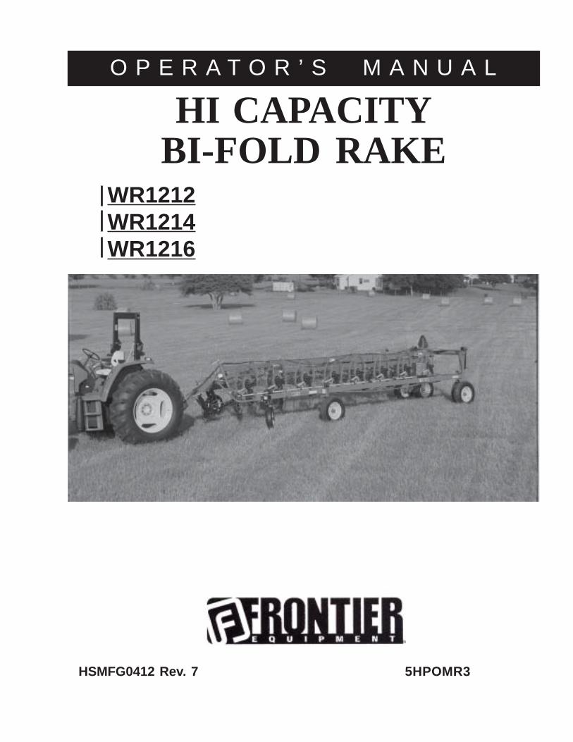
HSMFG0412 Rev. 7 5HPOMR3
HI CAPACITY
WR1212WR1214WR1216
O P E R A T O R ’ S M A N U A L
BI-FOLD RAKE
FRONTIER WR1212/WR1214/WR1216
Table of contents . . . . . . . . . . . . . . . . . . . . . . . . . . . . . . . . . . . . . . . . . . . . . . . . . . . . . . . . . . . . . . . . . . . 1
Warranty & Notes. . . . . . . . . . . . . . . . . . . . . . . . . . . . . . . . . . . . . . . . . . . . . . . . . . . . . . . . . . . . . . . . . .1-2
Dealer Pre-Delivery Checklist. . . . . . . . . . . . . . . . . . . . . . . . . . . . . . . . . . . . . . . . . . . . . . . . . . . . . . . . .3-4
Dealer Delivery Checklist. . . . . . . . . . . . . . . . . . . . . . . . . . . . . . . . . . . . . . . . . . . . . . . . . . . . . . . . . . . . 5-6
Specification. . . . . . . . . . . . . . . . . . . . . . . . . . . . . . . . . . . . . . . . . . . . . . . . . . . . . . . . . . . . . . . 7
Be Alert Symbol. . . . . . . . . . . . . . . . . . . . . . . . . . . . . . . . . . . . . . . . . . . . . . . . . . . . . . . . . . . . . . . . . . . . . 8
Explanation of Safety Signs. . . . . . . . . . . . . . . . . . . . . . . . . . . . . . . . . . . . . . . . . . . . . . . . . . . . . . . . . . . 9
Warning - Owner Must Read and Understand. . . . . . . . . . . . . . . . . . . . . . . . . . . . . . . . . . . . . . . . . . . . 10
Danger - Warning Signs. . . . . . . . . . . . . . . . . . . . . . . . . . . . . . . . . . . . . . . . . . . . . . . . . . . . . . . . . . . . . . 11
Bolt Torque Chart. . . . . . . . . . . . . . . . . . . . . . . . . . . . . . . . . . . . . . . . . . . . . . . . . . . . . . . . . . . . . . . . . . . .12
Set-up & Assembly . . . . . . . . . . . . . . . . . . . . . . . . . . . . . . . . . . . . . . . . . . . . . . . . . . . . . . . . . . . . . . . . . . . 13
Preparing for Operation. . . . . . . . . . . . . . . . . . . . . . . . . . . . . . . . . . . . . . . . . . . . . . . . . . . . . . . . . . . . . . . . 14
Transporting. . . . . . . . . . . . . . . . . . . . . . . . . . . . . . . . . . . . . . . . . . . . . . . . . . . . . . . . . . . . . . . . . . . . . . 15
Operation & Adjustments. . . . . . . . . . . . . . . . . . . . . . . . . . . . . . . . . . . . . . . . . . . . . . . . . . . . . . . . . . . 16-17
Optional Equipment. . . . . . . . . . . . . . . . . . . . . . . . . . . . . . . . . . . . . . . . . . . . . . . . . . . . . . . . . . . . . . . . .18
Lubrication Guide. . . . . . . . . . . . . . . . . . . . . . . . . . . . . . . . . . . . . . . . . . . . . . . . . . . . . . . . . . . . . . . . . . 19
Decal Location & Identification. . . . . . . . . . . . . . . . . . . . . . . . . . . . . . . . . . . . . . . . . . . . . . . . . . . . .20-22
Trouble Shooting. . . . . . . . . . . . . . . . . . . . . . . . . . . . . . . . . . . . . . . . . . . . . . . . . . . . . . . . . . . . . . . . . . . 23
Instructions for Ordering parts - About Improvements. . . . . . . . . . . . . . . . . . . . . . . . . . . . . . . . . . . . . 24
Service Notes. . . . . . . . . . . . . . . . . . . . . . . . . . . . . . . . . . . . . . . . . . . . . . . . . . . . . . . . . . . . . . .25
Parts. . . . . . . . . . . . . . . . . . . . . . . . . . . . . . . . . . . . . . . . . . . . . . . . . . . . . . . . . . . . . . . . . . . . . 26-59
Parts Notes. . . . . . . . . . . . . . . . . . . . . . . . . . . . . . . . . . . . . . . . . . . . . . . . . . . . . . . . . . . . . . . 60
Specifications. . . . . . . . . . . . . . . . . . . . . . . . . . . . . . . . . . . . . . . . . . . . . . . . . . . . . . . .Inside Back Cover
CONTENTSPARTS AND OPERATOR’S MANUAL

-1-
NOTES
WARRANTY:Warranty coverage is provided by John Deere according to the terms of theAgricultural/Commercial & Consumer Equipment Warranty Statement. Carefully read thewarranty statement on the back of your original purchase order for details on coverageand limitations of this warranty.

PAGE INTENTIONALLY LEFT BLANK
-2-
-3-
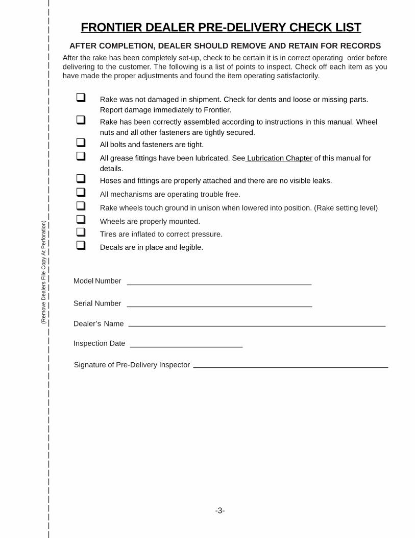
FRONTIER DEALER PRE-DELIVERY CHECK LIST(R
emov
e D
eale
rs F
ile C
opy
At P
erfo
ratio
n)AFTER COMPLETION, DEALER SHOULD REMOVE AND RETAIN FOR RECORDS
After the rake has been completely set-up, check to be certain it is in correct operating order beforedelivering to the customer. The following is a list of points to inspect. Check off each item as youhave made the proper adjustments and found the item operating satisfactorily.
! Rake was not damaged in shipment. Check for dents and loose or missing parts.Report damage immediately to Frontier.
! Rake has been correctly assembled according to instructions in this manual. Wheelnuts and all other fasteners are tightly secured.
! All bolts and fasteners are tight.
! All grease fittings have been lubricated. See Lubrication Chapter of this manual fordetails.
! Hoses and fittings are properly attached and there are no visible leaks.
! All mechanisms are operating trouble free.
! Rake wheels touch ground in unison when lowered into position. (Rake setting level)
! Wheels are properly mounted.
! Tires are inflated to correct pressure.
! Decals are in place and legible.
Model Number
Serial Number
Dealer’s Name
Inspection Date
Signature of Pre-Delivery Inspector

PAGE INTENTIONALLY LEFT BLANK
-4-
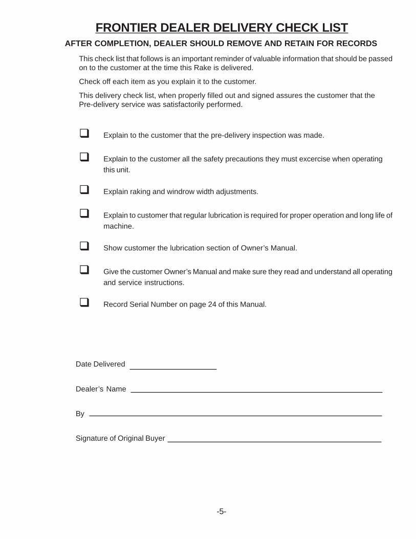
AFTER COMPLETION, DEALER SHOULD REMOVE AND RETAIN FOR RECORDS
This check list that follows is an important reminder of valuable information that should be passedon to the customer at the time this Rake is delivered.
Check off each item as you explain it to the customer.
This delivery check list, when properly filled out and signed assures the customer that thePre-delivery service was satisfactorily performed.
! Explain to the customer that the pre-delivery inspection was made.
! Explain to the customer all the safety precautions they must excercise when operatingthis unit.
! Explain raking and windrow width adjustments.
! Explain to customer that regular lubrication is required for proper operation and long life ofmachine.
! Show customer the lubrication section of Owner’s Manual.
! Give the customer Owner’s Manual and make sure they read and understand all operatingand service instructions.
! Record Serial Number on page 24 of this Manual.
Date Delivered
Dealer’s Name
By
Signature of Original Buyer
FRONTIER DEALER DELIVERY CHECK LIST
-5-

PAGE INTENTIONALLY LEFT BLANK
-6-
FRONTIER MODEL WR1212, WR1214 & WR1216HI CAPACITY BI-FOLD RAKE
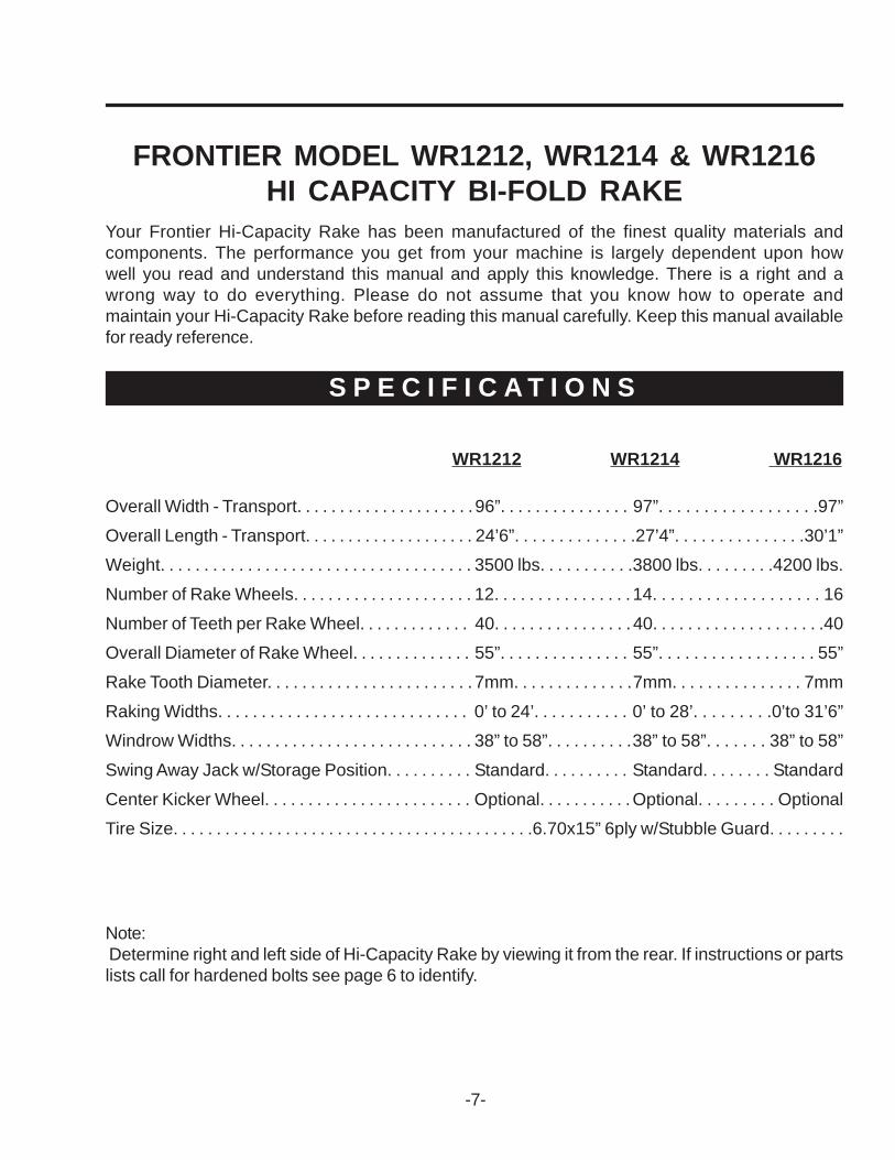
Your Frontier Hi-Capacity Rake has been manufactured of the finest quality materials andcomponents. The performance you get from your machine is largely dependent upon howwell you read and understand this manual and apply this knowledge. There is a right and awrong way to do everything. Please do not assume that you know how to operate andmaintain your Hi-Capacity Rake before reading this manual carefully. Keep this manual availablefor ready reference.
S P E C I F I C A T I O N S
WR1212 WR1214 WR1216
Note: Determine right and left side of Hi-Capacity Rake by viewing it from the rear. If instructions or partslists call for hardened bolts see page 6 to identify.
-7-
Overall Width - Transport. . . . . . . . . . . . . . . . . . . . .96”. . . . . . . . . . . . . . . 97”. . . . . . . . . . . . . . . . . .97”
Overall Length - Transport. . . . . . . . . . . . . . . . . . . . 24’6”. . . . . . . . . . . . . .27’4”. . . . . . . . . . . . . . .30’1”Weight. . . . . . . . . . . . . . . . . . . . . . . . . . . . . . . . . . . . 3500 lbs. . . . . . . . . . .3800 lbs. . . . . . . . .4200 lbs.
Number of Rake Wheels. . . . . . . . . . . . . . . . . . . . . 12. . . . . . . . . . . . . . . . 14. . . . . . . . . . . . . . . . . . . 16
Number of Teeth per Rake Wheel. . . . . . . . . . . . . 40. . . . . . . . . . . . . . . . 40. . . . . . . . . . . . . . . . . . . .40Overall Diameter of Rake Wheel. . . . . . . . . . . . . . 55”. . . . . . . . . . . . . . . 55”. . . . . . . . . . . . . . . . . . 55”
Rake Tooth Diameter. . . . . . . . . . . . . . . . . . . . . . . . 7mm. . . . . . . . . . . . . .7mm. . . . . . . . . . . . . . . 7mm
Raking Widths. . . . . . . . . . . . . . . . . . . . . . . . . . . . . 0’ to 24’. . . . . . . . . . . 0’ to 28’. . . . . . . . .0’to 31’6”Windrow Widths. . . . . . . . . . . . . . . . . . . . . . . . . . . . 38” to 58”. . . . . . . . . .38” to 58”. . . . . . . 38” to 58”
Swing Away Jack w/Storage Position. . . . . . . . . . Standard. . . . . . . . . . Standard. . . . . . . . Standard
Center Kicker Wheel. . . . . . . . . . . . . . . . . . . . . . . . Optional. . . . . . . . . . .Optional. . . . . . . . . OptionalTire Size. . . . . . . . . . . . . . . . . . . . . . . . . . . . . . . . . . . . . . . . . .6.70x15” 6ply w/Stubble Guard. . . . . . . . .

BEALERT! YOUR SAFETY
IS INVOLVED.
THIS SYMBOL IS USED THROUGHOUT THIS BOOK WHENEVER YOUR PERSONAL SAFETY ISINVOLVED. TAKE TIME TO BE CAREFUL. REMEMBER: THE CAREFUL OPERATOR IS THE BESTOPERATOR. MOST ACCIDENTS ARE CAUSED BY HUMAN ERROR. CERTAIN PRECAUTIONSMUST BE OBSERVED TO PREVENT THE POSSIBILITY OF INJURY OR DAMAGE.
TRACTORSThis operator’s manual uses the term “Tractor” when identifying the power source for towingand lifting rake.
-8-
SAFETY INFORMATION
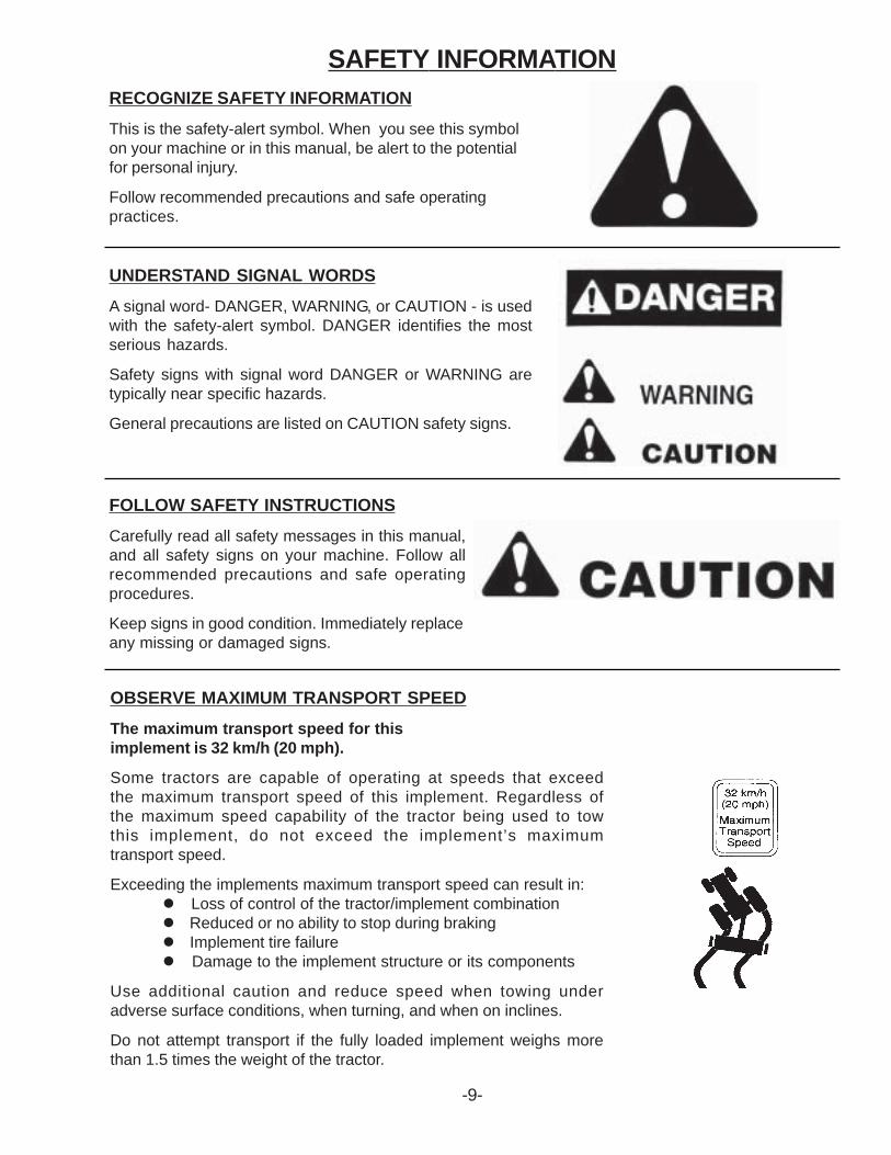
RECOGNIZE SAFETY INFORMATIONThis is the safety-alert symbol. When you see this symbolon your machine or in this manual, be alert to the potentialfor personal injury.
Follow recommended precautions and safe operatingpractices.
UNDERSTAND SIGNAL WORDSA signal word- DANGER, WARNING, or CAUTION - is usedwith the safety-alert symbol. DANGER identifies the mostserious hazards.
Safety signs with signal word DANGER or WARNING aretypically near specific hazards.
General precautions are listed on CAUTION safety signs.
FOLLOW SAFETY INSTRUCTIONSCarefully read all safety messages in this manual,and all safety signs on your machine. Follow allrecommended precautions and safe operatingprocedures.
Keep signs in good condition. Immediately replaceany missing or damaged signs.
-9-
OBSERVE MAXIMUM TRANSPORT SPEEDThe maximum transport speed for thisimplement is 32 km/h (20 mph).
Some tractors are capable of operating at speeds that exceedthe maximum transport speed of this implement. Regardless ofthe maximum speed capability of the tractor being used to towthis implement, do not exceed the implement’s maximumtransport speed.
Exceeding the implements maximum transport speed can result in:" Loss of control of the tractor/implement combination" Reduced or no ability to stop during braking" Implement tire failure" Damage to the implement structure or its components
Use additional caution and reduce speed when towing underadverse surface conditions, when turning, and when on inclines.
Do not attempt transport if the fully loaded implement weighs morethan 1.5 times the weight of the tractor.
SAFETY INFORMATION
TRACTORSThis operators manual uses the term “Tractor” when identifying the power source for towingand lifting rake.
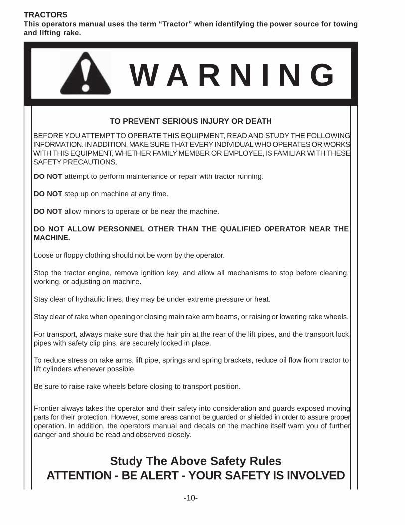
W A R N I N GTO PREVENT SERIOUS INJURY OR DEATH
Study The Above Safety RulesATTENTION - BE ALERT - YOUR SAFETY IS INVOLVED
BEFORE YOU ATTEMPT TO OPERATE THIS EQUIPMENT, READ AND STUDY THE FOLLOWINGINFORMATION. IN ADDITION, MAKE SURE THAT EVERY INDIVIDUAL WHO OPERATES OR WORKSWITH THIS EQUIPMENT, WHETHER FAMILY MEMBER OR EMPLOYEE, IS FAMILIAR WITH THESESAFETY PRECAUTIONS.
Frontier always takes the operator and their safety into consideration and guards exposed movingparts for their protection. However, some areas cannot be guarded or shielded in order to assure properoperation. In addition, the operators manual and decals on the machine itself warn you of furtherdanger and should be read and observed closely.
-10-
DO NOT attempt to perform maintenance or repair with tractor running.
DO NOT step up on machine at any time.
DO NOT allow minors to operate or be near the machine.
DO NOT ALLOW PERSONNEL OTHER THAN THE QUALIFIED OPERATOR NEAR THEMACHINE.
Loose or floppy clothing should not be worn by the operator.
Stop the tractor engine, remove ignition key, and allow all mechanisms to stop before cleaning,working, or adjusting on machine.
Stay clear of hydraulic lines, they may be under extreme pressure or heat.
Stay clear of rake when opening or closing main rake arm beams, or raising or lowering rake wheels.
For transport, always make sure that the hair pin at the rear of the lift pipes, and the transport lockpipes with safety clip pins, are securely locked in place.
To reduce stress on rake arms, lift pipe, springs and spring brackets, reduce oil flow from tractor tolift cylinders whenever possible.
Be sure to raise rake wheels before closing to transport position.
-11-
SAFETY INFORMATION
-12-
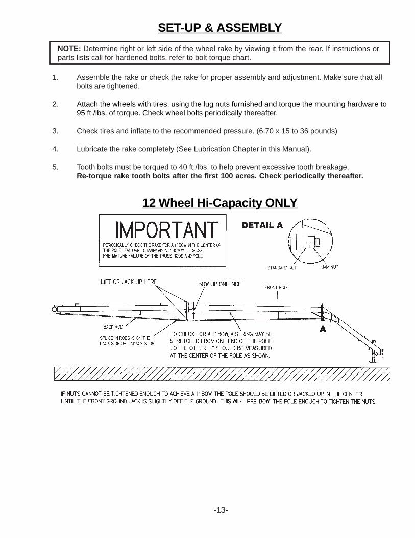
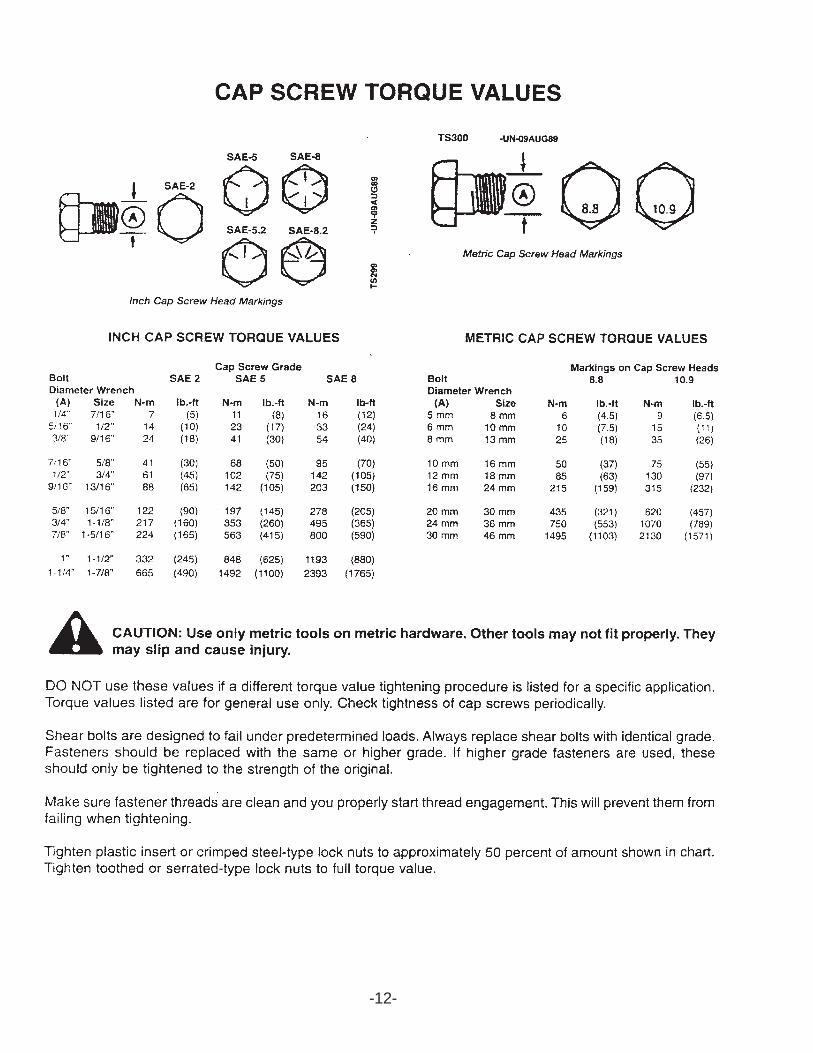
SET-UP & ASSEMBLYNOTE: Determine right or left side of the wheel rake by viewing it from the rear. If instructions orparts lists call for hardened bolts, refer to bolt torque chart.
1. Assemble the rake or check the rake for proper assembly and adjustment. Make sure that allbolts are tightened.
2. Attach the wheels with tires, using the lug nuts furnished and torque the mounting hardware to95 ft./lbs. of torque. Check wheel bolts periodically thereafter.
3. Check tires and inflate to the recommended pressure. (6.70 x 15 to 36 pounds)
4. Lubricate the rake completely (See Lubrication Chapter in this Manual).
5. Tooth bolts must be torqued to 40 ft./lbs. to help prevent excessive tooth breakage.Re-torque rake tooth bolts after the first 100 acres. Check periodically thereafter.
12 Wheel Hi-Capacity ONLY
-13-
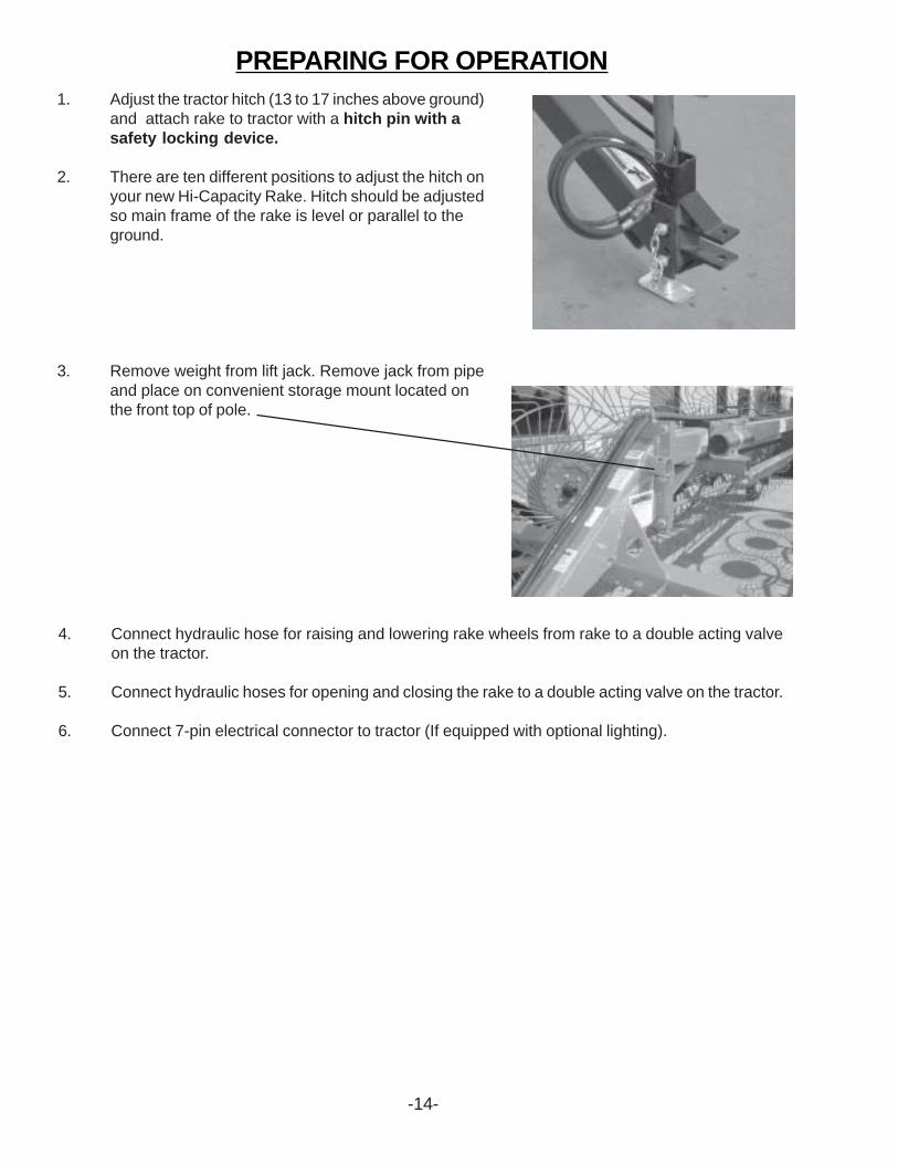
PREPARING FOR OPERATION1. Adjust the tractor hitch (13 to 17 inches above ground)
and attach rake to tractor with a hitch pin with asafety locking device.
2. There are ten different positions to adjust the hitch onyour new Hi-Capacity Rake. Hitch should be adjustedso main frame of the rake is level or parallel to theground.
3. Remove weight from lift jack. Remove jack from pipeand place on convenient storage mount located onthe front top of pole.
4. Connect hydraulic hose for raising and lowering rake wheels from rake to a double acting valveon the tractor.
5. Connect hydraulic hoses for opening and closing the rake to a double acting valve on the tractor.
6. Connect 7-pin electrical connector to tractor (If equipped with optional lighting).
-14-
-15-
TRANSPORT LOCKS
TRANSPORTING
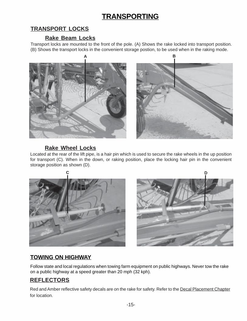
Rake Beam LocksTransport locks are mounted to the front of the pole. (A) Shows the rake locked into transport position.(B) Shows the transport locks in the convenient storage postion, to be used when in the raking mode.
Rake Wheel LocksLocated at the rear of the lift pipe, is a hair pin which is used to secure the rake wheels in the up positionfor transport (C). When in the down, or raking position, place the locking hair pin in the convenientstorage position as shown (D).
TOWING ON HIGHWAYFollow state and local regulations when towing farm equipment on public highways. Never tow the rakeon a public highway at a speed greater than 20 mph (32 kph).
REFLECTORSRed and Amber reflective safety decals are on the rake for safety. Refer to the Decal Placement Chapterfor location.
A B
C D
-16-
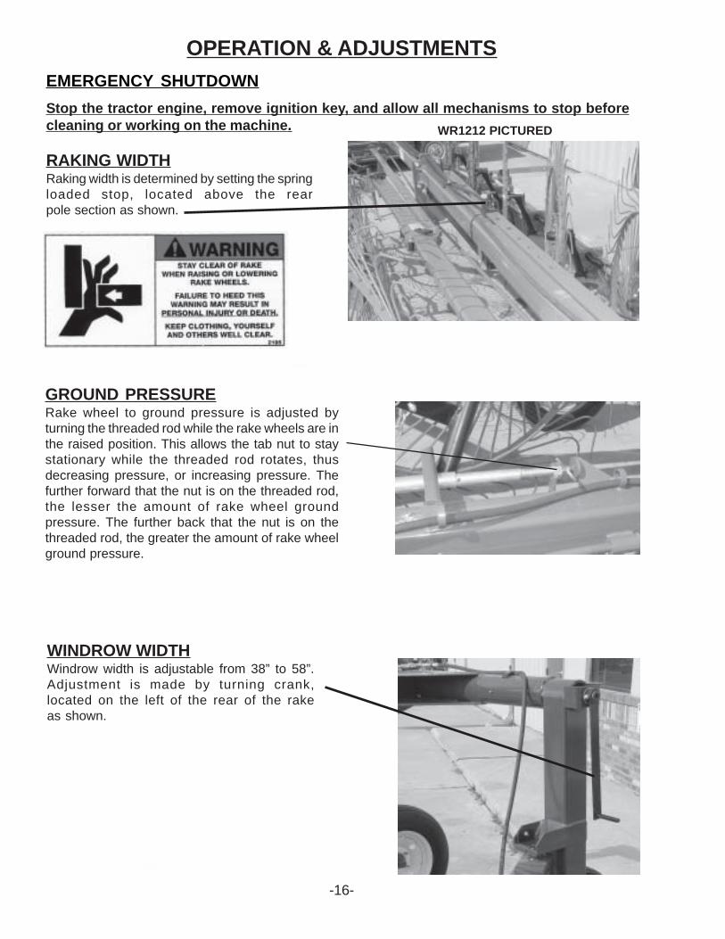
WR1212 PICTURED
OPERATION & ADJUSTMENTSEMERGENCY SHUTDOWNStop the tractor engine, remove ignition key, and allow all mechanisms to stop beforecleaning or working on the machine.
RAKING WIDTHRaking width is determined by setting the springloaded stop, located above the rearpole section as shown.
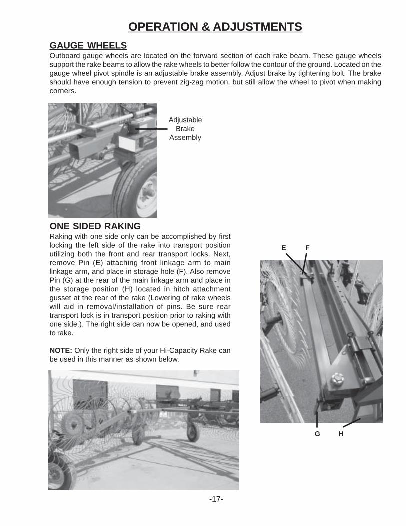
GROUND PRESSURERake wheel to ground pressure is adjusted byturning the threaded rod while the rake wheels are inthe raised position. This allows the tab nut to staystationary while the threaded rod rotates, thusdecreasing pressure, or increasing pressure. Thefurther forward that the nut is on the threaded rod,the lesser the amount of rake wheel groundpressure. The further back that the nut is on thethreaded rod, the greater the amount of rake wheelground pressure.
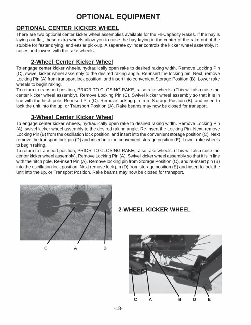
WINDROW WIDTHWindrow width is adjustable from 38” to 58”.Adjustment is made by turning crank,located on the left of the rear of the rakeas shown.
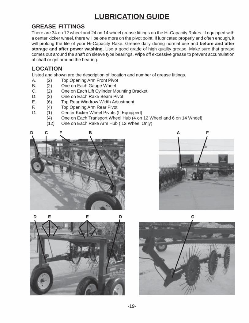
GAUGE WHEELSOutboard gauge wheels are located on the forward section of each rake beam. These gauge wheelssupport the rake beams to allow the rake wheels to better follow the contour of the ground. Located on thegauge wheel pivot spindle is an adjustable brake assembly. Adjust brake by tightening bolt. The brakeshould have enough tension to prevent zig-zag motion, but still allow the wheel to pivot when makingcorners.
OPERATION & ADJUSTMENTS
AdjustableBrake
Assembly
ONE SIDED RAKINGRaking with one side only can be accomplished by firstlocking the left side of the rake into transport positionutilizing both the front and rear transport locks. Next,remove Pin (E) attaching front linkage arm to mainlinkage arm, and place in storage hole (F). Also removePin (G) at the rear of the main linkage arm and place inthe storage position (H) located in hitch attachmentgusset at the rear of the rake (Lowering of rake wheelswill aid in removal/installation of pins. Be sure reartransport lock is in transport position prior to raking withone side.). The right side can now be opened, and usedto rake.
NOTE: Only the right side of your Hi-Capacity Rake canbe used in this manner as shown below.
E F
G H
-17-
OPTIONAL EQUIPMENT
-18-
OPTIONAL CENTER KICKER WHEELThere are two optional center kicker wheel assemblies available for the Hi-Capacity Rakes. If the hay islaying out flat, these extra wheels allow you to raise the hay laying in the center of the rake out of thestubble for faster drying, and easier pick-up. A separate cylinder controls the kicker wheel assembly. Itraises and lowers with the rake wheels.
2-Wheel Center Kicker WheelTo engage center kicker wheels, hydraulically open rake to desired raking width. Remove Locking Pin(C), swivel kicker wheel assembly to the desired raking angle. Re-insert the locking pin. Next, removeLocking Pin (A) from transport lock position, and insert into convenient Storage Position (B). Lower rakewheels to begin raking.To return to transport position, PRIOR TO CLOSING RAKE, raise rake wheels. (This will also raise thecenter kicker wheel assembly). Remove Locking Pin (C), Swivel kicker wheel assembly so that it is inline with the hitch pole. Re-insert Pin (C). Remove locking pin from Storage Position (B), and insert tolock the unit into the up, or Transport Position (A). Rake beams may now be closed for transport.
3-Wheel Center Kicker WheelTo engage center kicker wheels, hydraulically open rake to desired raking width. Remove Locking Pin(A), swivel kicker wheel assembly to the desired raking angle. Re-insert the Locking Pin. Next, removeLocking Pin (B) from the oscillation lock position, and insert into the convenient storage position (C). Nextremove the transport lock pin (D) and insert into the convenient storage position (E). Lower rake wheelsto begin raking.To return to transport position, PRIOR TO CLOSING RAKE, raise rake wheels. (This will also raise thecenter kicker wheel assembly). Remove Locking Pin (A), Swivel kicker wheel assembly so that it is in linewith the hitch pole. Re-insert Pin (A). Remove locking pin from Storage Position (C), and re-insert pin (B)into the oscillation lock position. Next remove lock pin (D) from storage position (E) and insert to lock theunit into the up, or Transport Position. Rake beams may now be closed for transport.
C A B
2-WHEEL KICKER WHEEL
C A B D E
LUBRICATION GUIDE
-19-
GREASE FITTINGSThere are 34 on 12 wheel and 24 on 14 wheel grease fittings on the Hi-Capacity Rakes. If equipped witha center kicker wheel, there will be one more on the pivot point. If lubricated properly and often enough, itwill prolong the life of your Hi-Capacity Rake. Grease daily during normal use and before and afterstorage and after power washing. Use a good grade of high quailty grease. Make sure that greasecomes out around the shaft on sleeve type bearings. Wipe off excessive grease to prevent accumulationof chaff or grit around the bearing.
LOCATIONListed and shown are the description of location and number of grease fittings.A. (2) Top Opening Arm Front PivotB. (2) One on Each Gauge WheelC. (2) One on Each Lift Cylinder Mounting BracketD. (2) One on Each Rake Beam PivotE. (6) Top Rear Windrow Width AdjustmentF. (4) Top Opening Arm Rear PivotG. (1) Center Kicker Wheel Pivots (If Equipped)
(4) One on Each Transport Wheel Hub (4 on 12 Wheel and 6 on 14 Wheel)(12) One on Each Rake Arm Hub ( 12 Wheel Only)
D C F B A F
D E E D G
-20-
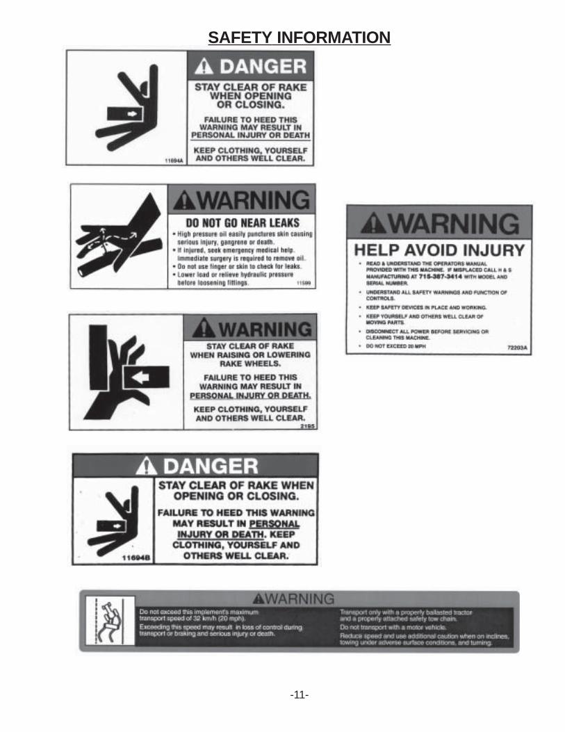
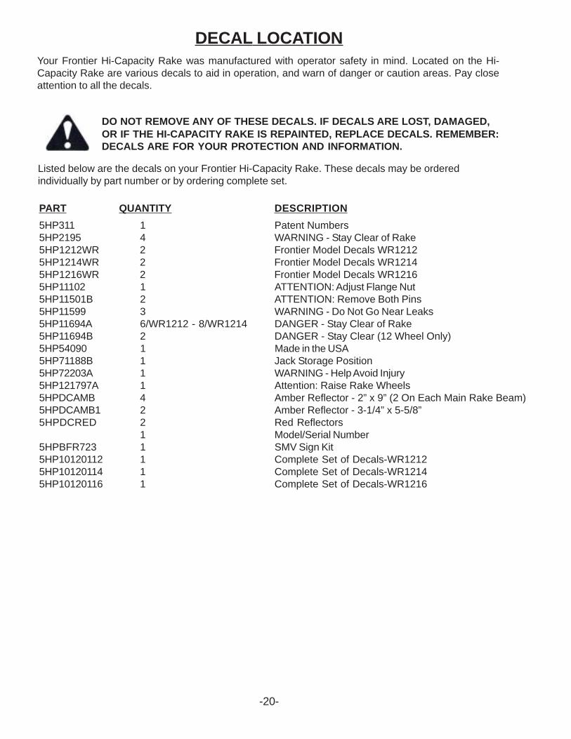
DECAL LOCATIONYour Frontier Hi-Capacity Rake was manufactured with operator safety in mind. Located on the Hi-Capacity Rake are various decals to aid in operation, and warn of danger or caution areas. Pay closeattention to all the decals.
DO NOT REMOVE ANY OF THESE DECALS. IF DECALS ARE LOST, DAMAGED,` OR IF THE HI-CAPACITY RAKE IS REPAINTED, REPLACE DECALS. REMEMBER:
DECALS ARE FOR YOUR PROTECTION AND INFORMATION.
Listed below are the decals on your Frontier Hi-Capacity Rake. These decals may be orderedindividually by part number or by ordering complete set.
5HP311 1 Patent Numbers5HP2195 4 WARNING - Stay Clear of Rake5HP1212WR 2 Frontier Model Decals WR12125HP1214WR 2 Frontier Model Decals WR12145HP1216WR 2 Frontier Model Decals WR12165HP11102 1 ATTENTION: Adjust Flange Nut5HP11501B 2 ATTENTION: Remove Both Pins5HP11599 3 WARNING - Do Not Go Near Leaks5HP11694A 6/WR1212 - 8/WR1214 DANGER - Stay Clear of Rake5HP11694B 2 DANGER - Stay Clear (12 Wheel Only)5HP54090 1 Made in the USA5HP71188B 1 Jack Storage Position5HP72203A 1 WARNING - Help Avoid Injury5HP121797A 1 Attention: Raise Rake Wheels5HPDCAMB 4 Amber Reflector - 2” x 9” (2 On Each Main Rake Beam)5HPDCAMB1 2 Amber Reflector - 3-1/4” x 5-5/8”5HPDCRED 2 Red Reflectors
1 Model/Serial Number5HPBFR723 1 SMV Sign Kit5HP10120112 1 Complete Set of Decals-WR12125HP10120114 1 Complete Set of Decals-WR12145HP10120116 1 Complete Set of Decals-WR1216
PART QUANTITY DESCRIPTION
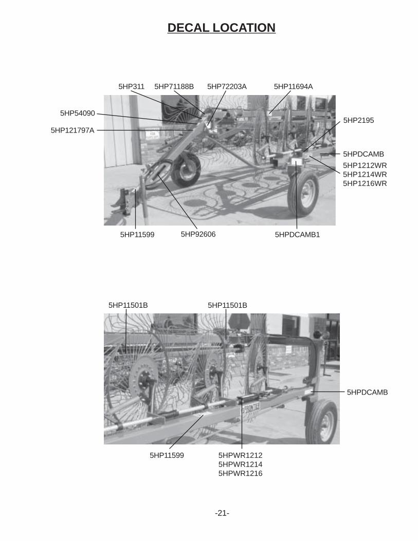
DECAL LOCATION
5HP11599 5HP92606
5HP2195
5HP72203A5HP71188B5HP311
5HP54090
5HP121797A
5HPDCAMB1
5HP1212WR5HP1214WR5HP1216WR
5HP11501B
5HP11694A
5HPWR12125HPWR12145HPWR1216
5HP11599
5HP11501B
5HPDCAMB
5HPDCAMB
-21-
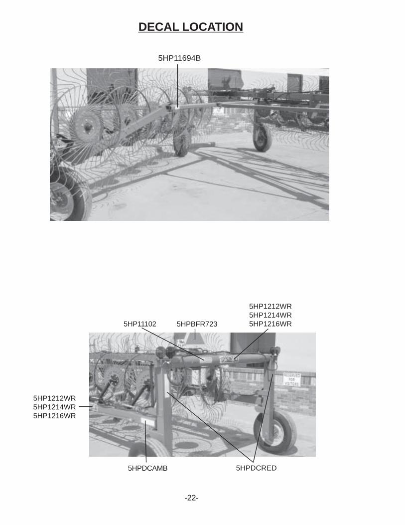
DECAL LOCATION
5HP11694B
5HPDCRED5HPDCAMB
5HP11102 5HPBFR723
5HP1212WR5HP1214WR5HP1216WR
5HP1212WR5HP1214WR5HP1216WR
-22-
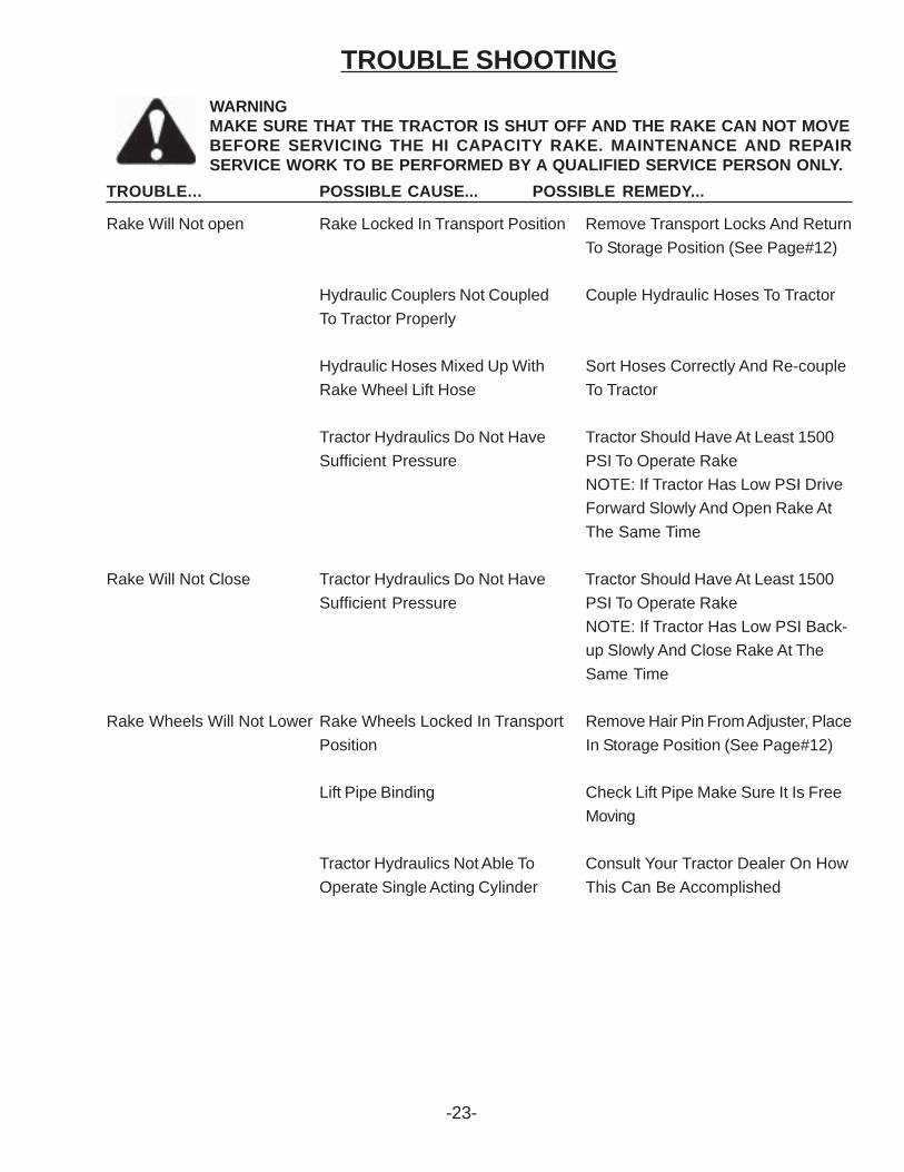
TROUBLE SHOOTINGWARNINGMAKE SURE THAT THE TRACTOR IS SHUT OFF AND THE RAKE CAN NOT MOVEBEFORE SERVICING THE HI CAPACITY RAKE. MAINTENANCE AND REPAIRSERVICE WORK TO BE PERFORMED BY A QUALIFIED SERVICE PERSON ONLY.
TROUBLE... POSSIBLE CAUSE... POSSIBLE REMEDY...
Rake Will Not open Rake Locked In Transport Position Remove Transport Locks And ReturnTo Storage Position (See Page#12)
Hydraulic Couplers Not Coupled Couple Hydraulic Hoses To TractorTo Tractor Properly
Hydraulic Hoses Mixed Up With Sort Hoses Correctly And Re-coupleRake Wheel Lift Hose To Tractor
Tractor Hydraulics Do Not Have Tractor Should Have At Least 1500Sufficient Pressure PSI To Operate Rake
NOTE: If Tractor Has Low PSI DriveForward Slowly And Open Rake AtThe Same Time
Rake Will Not Close Tractor Hydraulics Do Not Have Tractor Should Have At Least 1500Sufficient Pressure PSI To Operate Rake
NOTE: If Tractor Has Low PSI Back-up Slowly And Close Rake At TheSame Time
Rake Wheels Will Not Lower Rake Wheels Locked In Transport Remove Hair Pin From Adjuster, PlacePosition In Storage Position (See Page#12)
Lift Pipe Binding Check Lift Pipe Make Sure It Is FreeMoving
Tractor Hydraulics Not Able To Consult Your Tractor Dealer On HowOperate Single Acting Cylinder This Can Be Accomplished
-23-
-24-
INSTRUCTIONS FOR ORDERING PARTS
All service parts should be ordered through your authorized Frontier dealer.They will be able togive you faster service if you will provide them with the following:
1. Model & Serial Number - Both can be located on the left, rear main frame of your unit.2. All references to left or right apply to the machine as viewed from the rear.3. Parts should not be ordered from illustration only. Please order complete part number.4. If your dealer has to order parts - give shipping instructions: VIA truck - large pieces (please specify local truck lines) VIA United Parcel Service (include full address)
PLEASE RECORD NUMBERS FOR YOUR UNIT FOR QUICK REFERENCE
ABOUT IMPROVEMENTS
FRONTIER IS CONTINUALLY STRIVING TO IMPROVE IT’S PRODUCTS
We must therfore, reserve the right to make improvements or changes whenever it becomes practical todo so, without incurring any obligation to make changes or additions to the equipment previously sold.

SERVICE NOTES
-25-
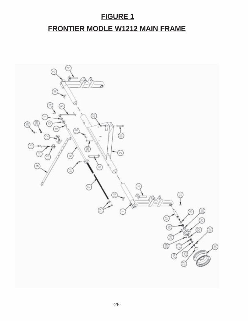
FIGURE 1
-26-
FRONTIER MODLE W1212 MAIN FRAME

FRONTIER MODLE W1212 MAIN FRAME
-27-
FIGURE 1
ITEM1234567891011121314151617181920212223*
24252627282930313233343536373839
PART #5HPBFR7545HPBFR4985HPBFR7555HPBFR7565HPBFR4235HPBFR4855HPBFR4205HPBFR6495HPBFR6115HPBFR4225HPBFR5235HPBFR6135HPBFR2395HPBFR2405HPBFR2415HP23N675HPBFR4495HPBFR575HP17G1455HP17G1465HPBFR605HPBFR615HPBFR625HPBFR755HPYWFL240055HPYNSL240105HPYPCT050105HPBFR665HPYBSD160055HPYNWL160055HPBFR675HPYPEX120255HPYBHH201105HPYNHX200055HPYBHH160105HPYNAC240055HPYBHH200855HPYBHH120905HPBFR6425HPYSHW10010
DESCRIPTIONRIGHT AXLE UPRIGHTREAR PIVOT ASSEMBLYLEFT AXLE UPRIGHTBEAM PIVOT SHAFTWIDTH ADJUSTMENT HANDLEREAR WIDTH ADJUSTMENT TUBEREAR WIDTH ADJUSTMENT RODSMV BRACKETWIDTH ADJUSTMENT BARWIDTH ADJUSTMENT COLLARPOLY WASHERWIDTH ADJUSTMENT STOPSLEEVE ADJUSTABLE LOCKSPRINGADJUSTMENT HANDLEHOSE HOLDERSPINDLESEALINNER BEARINGINNER RACEHUBOUTER RACEOUTER BEARINGCOMPLETE GROUND WHEEL HUBWASHER, FLAT, 3/4" USSHEX NUT, SLOTTED, 3/4"-16COTTER PIN, 5/32" X 1-1/2"HUB CAPSTUD BOLT, 1/2"-20 UNF X 1-7/8" (3/8" SHOULDER)WHEEL NUT, 1/2"-20 UNFWHEEL 5 X 15EXPANSION PIN, 3/8" X 2-3/4"BOLT, 5/8" X 8" GR. 5HEX NUT, 5/8"-11 PLATEDBOLT, 1/2" X 1" GR. 5HEX NUT, ACME, 3/4"-6BOLT, 5/8" X 5" GR. 5BOLT, 3/8" X 2-1/2" GR. 5WIDTH ADJUSTMENT SPACER5/16"-18 X 1-1/4" HEX WASHER SLOT TYPE F ZINCTHREAD CUTTING SCREW
NOTE: * (MEANS NOT SHOWN)
TANDEM OPTIONS: BFR509 RH TANDEM AXLE BFR510 LH TANDEM AXLE
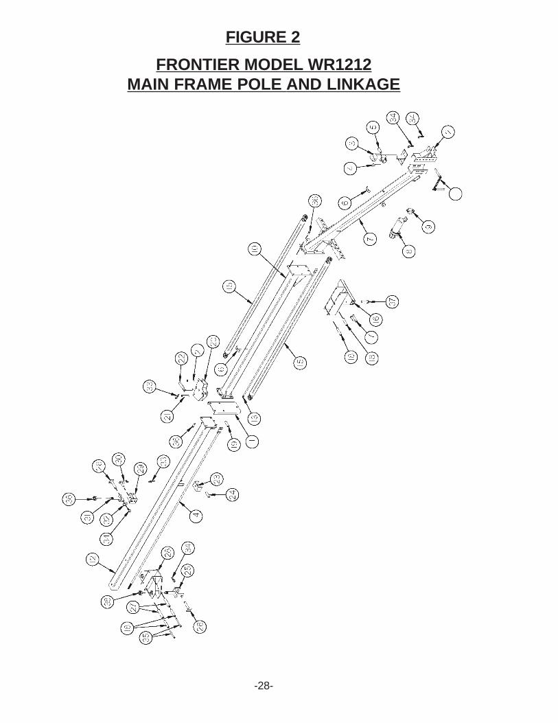
FIGURE 2
-28-
FRONTIER MODEL WR1212MAIN FRAME POLE AND LINKAGE

-29-
FIGURE 2FRONTIER MODEL WR1212
MAIN FRAME POLE AND LINKAGEITEM
12345*67891011121314151617181920212223242526272829303132333435363738
PART #5HPBFR4505HPBFR1575HPBFR7535HP12N1175HP5N785HP12N1185HPHE425HPBFR6605HPS5225HPS235HPBFR3855HPBFR3995HPBFR3975HPBFR5025HPBFR5035HPBFR3905HPBFR3875HPBFR3885HPBFR3895HPBFR3965HPBFR3985HPBFR4005HPBFR4015HPBFR4025HPBFR6345HPBFR4105HPBFR4135HPBFR4045HPBFR4405HPBFR4115HPBFR4125HPBFR4145HPBFR4415HPYPHR020105HPYPHR060405HPYBHH161605HPYBHH200255HPYBHH320105HPYNSL36005
DESCRIPTIONHITCH PINHITCHJACKJACK PIN & CHAINJACK HANDLEREPLACEMENT BEARINGHOSE HOLDERPOLEMANUAL HOLDERMANUAL CLAMP - LARGECENTER POLE SECTIONLINKAGE STOPBACK POLE SECTIONFRONT RODBACK RODFRONT LINKAGEFRONT LINKAGE SLIDERHOSE GUIDE SPACERSLIDER SPACERCYLINDER PINCENTER SLIDERCENTER SLIDER SPACERCENTER SLIDER PINHOSE GUIDECYLINDER PINBACK LINKAGE YOKE RHPIVOT YOKE SHAFT PINBACK SLIDER ROLLERBACK LINKAGE SLIDERBACK LINKAGE YOKE LHBACK LINKAGE YOKE PINLEFT PIVOT YOKE SHAFTSTOP WASHERHAIR PIN, #21-07HAIR PIN, 3/16" X 3-3/4"BOLT, 1/2" X 5-1/2" GR. 5BOLT, 5/8" X 2" GR. 5BOLT, 1"-8 X 3-1/2" GR. 5HEX NUT, SLOTTED, 1-1/4"-12
NOTE: * (MEANS NOT SHOWN)

-30-
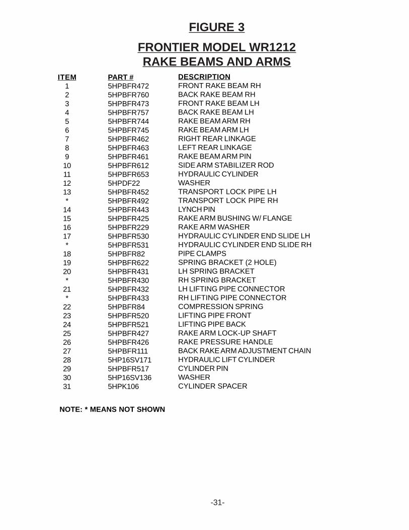
FIGURE 3FRONTIER MODEL WR1212RAKE BEAMS AND ARMS
-31-
FRONTIER MODEL WR1212RAKE BEAMS AND ARMS
FIGURE 3
ITEM12345678910111213*
14151617*
181920*
21*
22232425262728293031
PART #5HPBFR4725HPBFR7605HPBFR4735HPBFR7575HPBFR7445HPBFR7455HPBFR4625HPBFR4635HPBFR4615HPBFR6125HPBFR6535HPDF225HPBFR4525HPBFR4925HPBFR4435HPBFR4255HPBFR2295HPBFR5305HPBFR5315HPBFR825HPBFR6225HPBFR4315HPBFR4305HPBFR4325HPBFR4335HPBFR845HPBFR5205HPBFR5215HPBFR4275HPBFR4265HPBFR1115HP16SV1715HPBFR5175HP16SV1365HPK106
DESCRIPTIONFRONT RAKE BEAM RHBACK RAKE BEAM RHFRONT RAKE BEAM LHBACK RAKE BEAM LHRAKE BEAM ARM RHRAKE BEAM ARM LHRIGHT REAR LINKAGELEFT REAR LINKAGERAKE BEAM ARM PINSIDE ARM STABILIZER RODHYDRAULIC CYLINDERWASHERTRANSPORT LOCK PIPE LHTRANSPORT LOCK PIPE RHLYNCH PINRAKE ARM BUSHING W/ FLANGERAKE ARM WASHERHYDRAULIC CYLINDER END SLIDE LHHYDRAULIC CYLINDER END SLIDE RHPIPE CLAMPSSPRING BRACKET (2 HOLE)LH SPRING BRACKETRH SPRING BRACKETLH LIFTING PIPE CONNECTORRH LIFTING PIPE CONNECTORCOMPRESSION SPRINGLIFTING PIPE FRONTLIFTING PIPE BACKRAKE ARM LOCK-UP SHAFTRAKE PRESSURE HANDLEBACK RAKE ARM ADJUSTMENT CHAINHYDRAULIC LIFT CYLINDERCYLINDER PINWASHERCYLINDER SPACER
NOTE: * MEANS NOT SHOWN
-32-
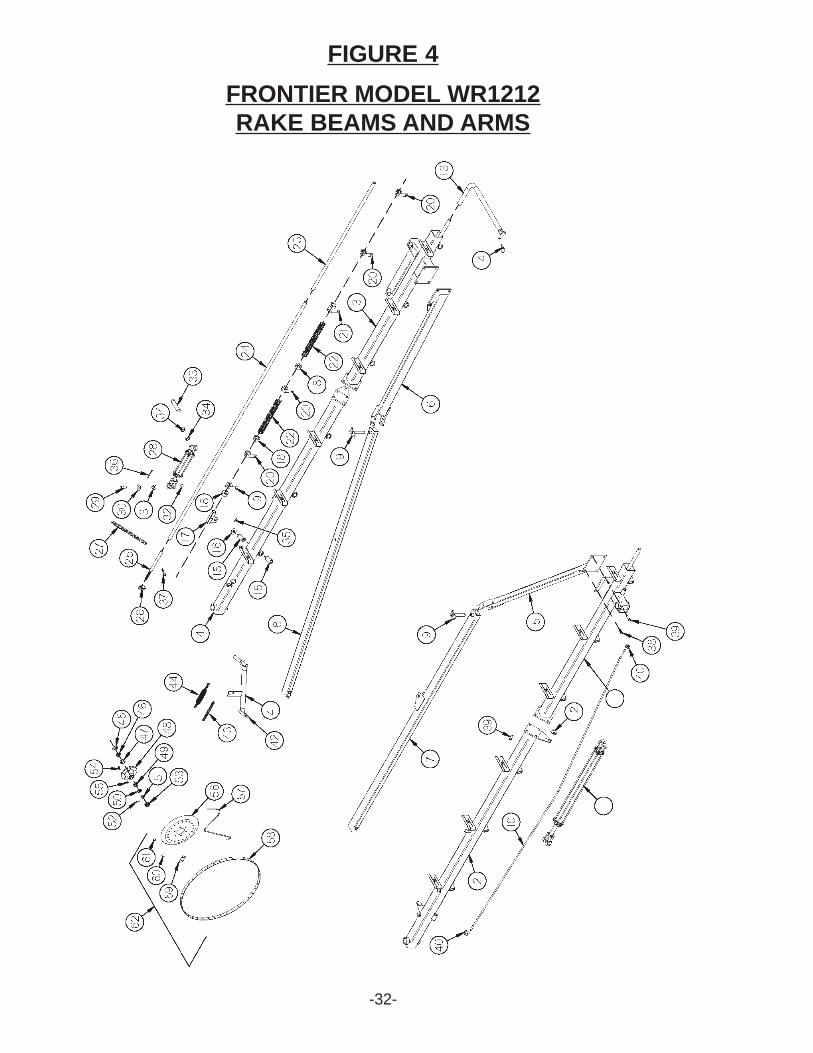
FIGURE 4FRONTIER MODEL WR1212RAKE BEAMS AND ARMS
-33-
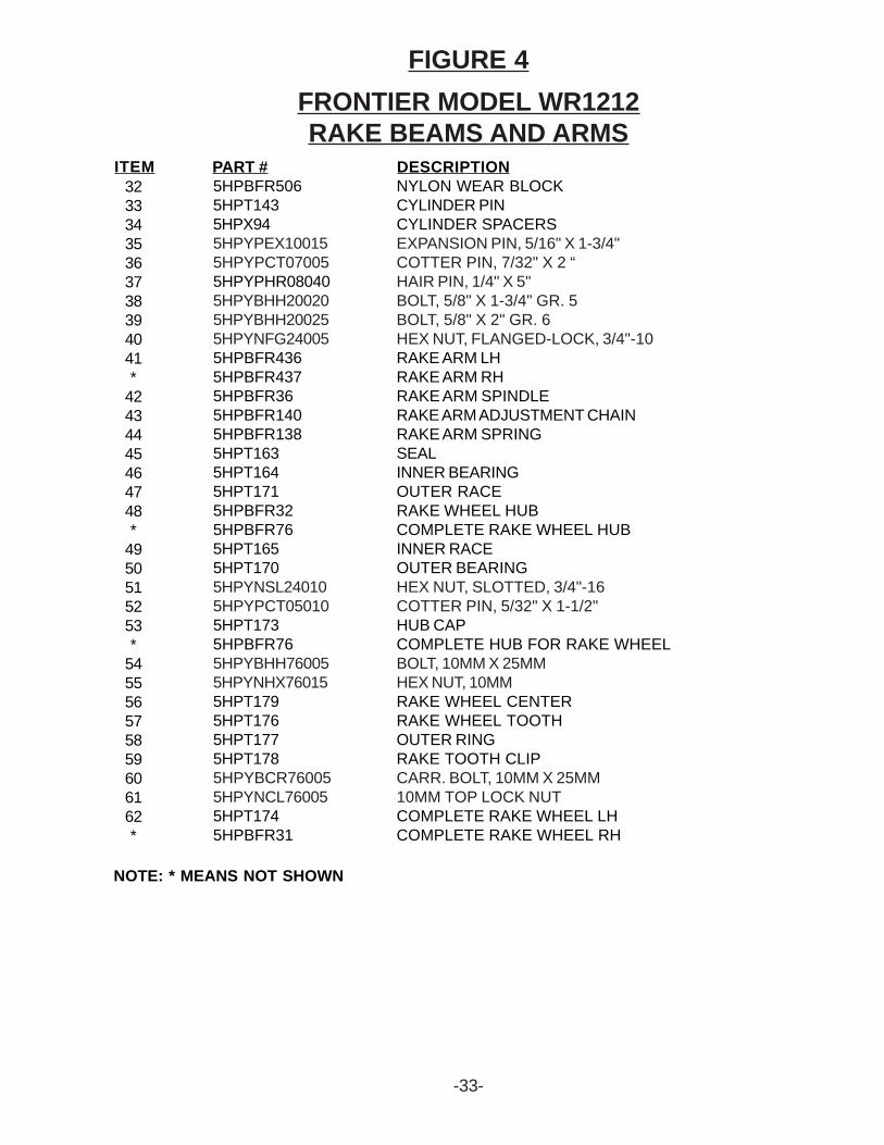
FIGURE 4FRONTIER MODEL WR1212RAKE BEAMS AND ARMS
32333435363738394041*
42434445464748*
4950515253*
545556575859606162*
5HPBFR5065HPT1435HPX945HPYPEX100155HPYPCT070055HPYPHR080405HPYBHH200205HPYBHH200255HPYNFG240055HPBFR4365HPBFR4375HPBFR365HPBFR1405HPBFR1385HPT1635HPT1645HPT1715HPBFR325HPBFR765HPT1655HPT1705HPYNSL240105HPYPCT050105HPT1735HPBFR765HPYBHH760055HPYNHX760155HPT1795HPT1765HPT1775HPT1785HPYBCR760055HPYNCL760055HPT1745HPBFR31
NYLON WEAR BLOCKCYLINDER PINCYLINDER SPACERSEXPANSION PIN, 5/16" X 1-3/4"COTTER PIN, 7/32" X 2 “HAIR PIN, 1/4" X 5"BOLT, 5/8" X 1-3/4" GR. 5BOLT, 5/8" X 2" GR. 6HEX NUT, FLANGED-LOCK, 3/4"-10RAKE ARM LHRAKE ARM RHRAKE ARM SPINDLERAKE ARM ADJUSTMENT CHAINRAKE ARM SPRINGSEALINNER BEARINGOUTER RACERAKE WHEEL HUBCOMPLETE RAKE WHEEL HUBINNER RACEOUTER BEARINGHEX NUT, SLOTTED, 3/4"-16COTTER PIN, 5/32" X 1-1/2"HUB CAPCOMPLETE HUB FOR RAKE WHEELBOLT, 10MM X 25MMHEX NUT, 10MMRAKE WHEEL CENTERRAKE WHEEL TOOTHOUTER RINGRAKE TOOTH CLIPCARR. BOLT, 10MM X 25MM10MM TOP LOCK NUTCOMPLETE RAKE WHEEL LHCOMPLETE RAKE WHEEL RH
ITEM PART # DESCRIPTION
NOTE: * MEANS NOT SHOWN
-34-
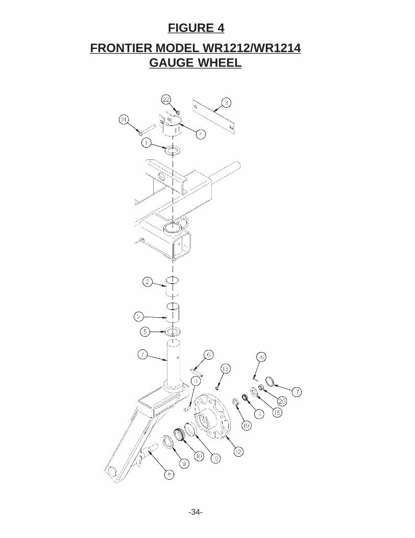
FIGURE 4FRONTIER MODEL WR1212/WR1214
GAUGE WHEEL
-35-
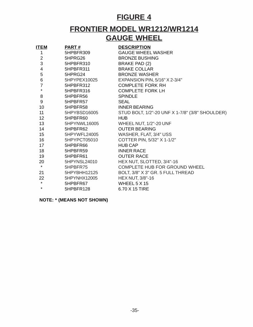
FIGURE 4FRONTIER MODEL WR1212/WR1214
GAUGE WHEELITEM
1234567*891011121314151617181920*
2122**
PART #5HPBFR3095HPRG265HPBFR3105HPBFR3115HPRG245HPYPEX100255HPBFR3125HPBFR3165HPBFR565HPBFR575HPBFR585HPYBSD160055HPBFR605HPYNWL160055HPBFR625HPYWFL240055HPYPCT050105HPBFR665HPBFR595HPBFR615HPYNSL240105HPBFR755HPYBHH121255HPYNHX120055HPBFR675HPBFR128
DESCRIPTIONGAUGE WHEEL WASHERBRONZE BUSHINGBRAKE PAD (2)BRAKE COLLARBRONZE WASHEREXPANSION PIN, 5/16" X 2-3/4"COMPLETE FORK RHCOMPLETE FORK LHSPINDLESEALINNER BEARINGSTUD BOLT, 1/2"-20 UNF X 1-7/8" (3/8" SHOULDER)HUBWHEEL NUT, 1/2"-20 UNFOUTER BEARINGWASHER, FLAT, 3/4" USSCOTTER PIN, 5/32" X 1-1/2"HUB CAPINNER RACEOUTER RACEHEX NUT, SLOTTED, 3/4"-16COMPLETE HUB FOR GROUND WHEELBOLT, 3/8" X 3" GR. 5 FULL THREADHEX NUT, 3/8"-16WHEEL 5 X 156.70 X 15 TIRE
NOTE: * (MEANS NOT SHOWN)
-36-
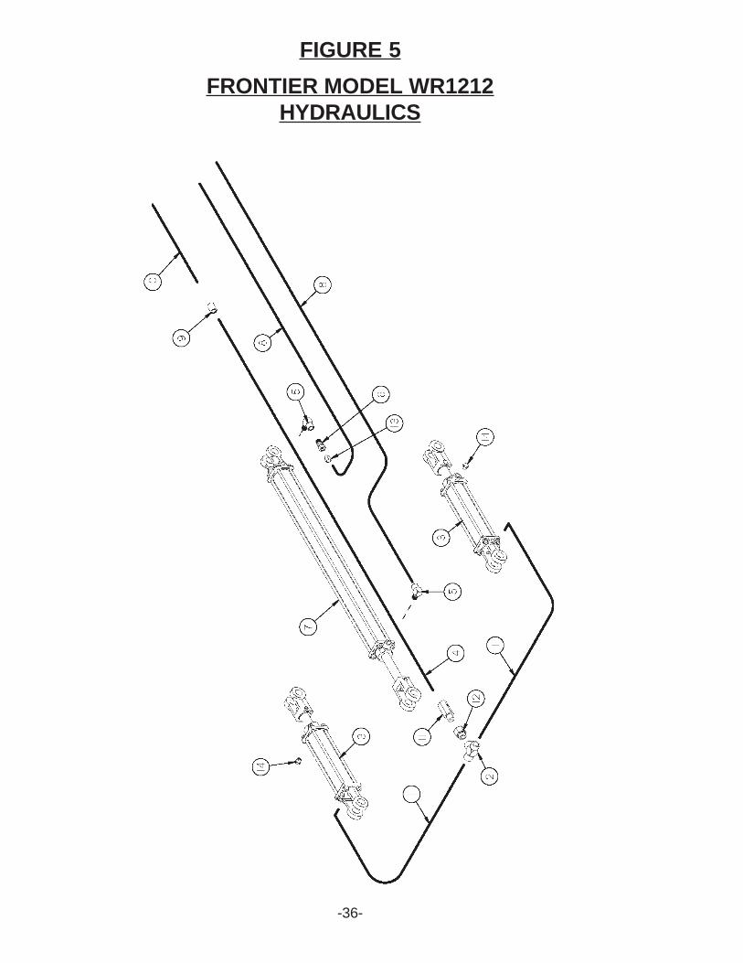
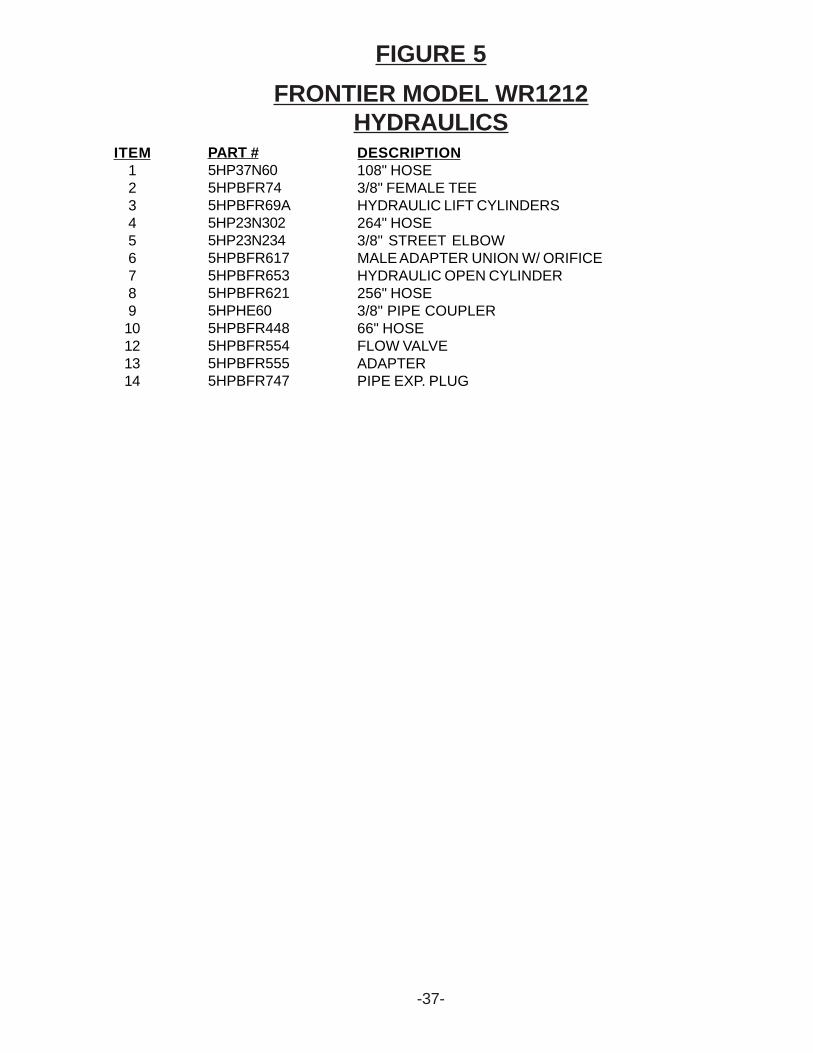
FIGURE 5FRONTIER MODEL WR1212
HYDRAULICS
-37-
FIGURE 5FRONTIER MODEL WR1212
HYDRAULICSITEM
12345678910121314
PART #5HP37N605HPBFR745HPBFR69A5HP23N3025HP23N2345HPBFR6175HPBFR6535HPBFR6215HPHE605HPBFR4485HPBFR5545HPBFR5555HPBFR747
DESCRIPTION108" HOSE3/8" FEMALE TEEHYDRAULIC LIFT CYLINDERS264" HOSE3/8" STREET ELBOWMALE ADAPTER UNION W/ ORIFICEHYDRAULIC OPEN CYLINDER256" HOSE3/8" PIPE COUPLER66" HOSEFLOW VALVEADAPTERPIPE EXP. PLUG
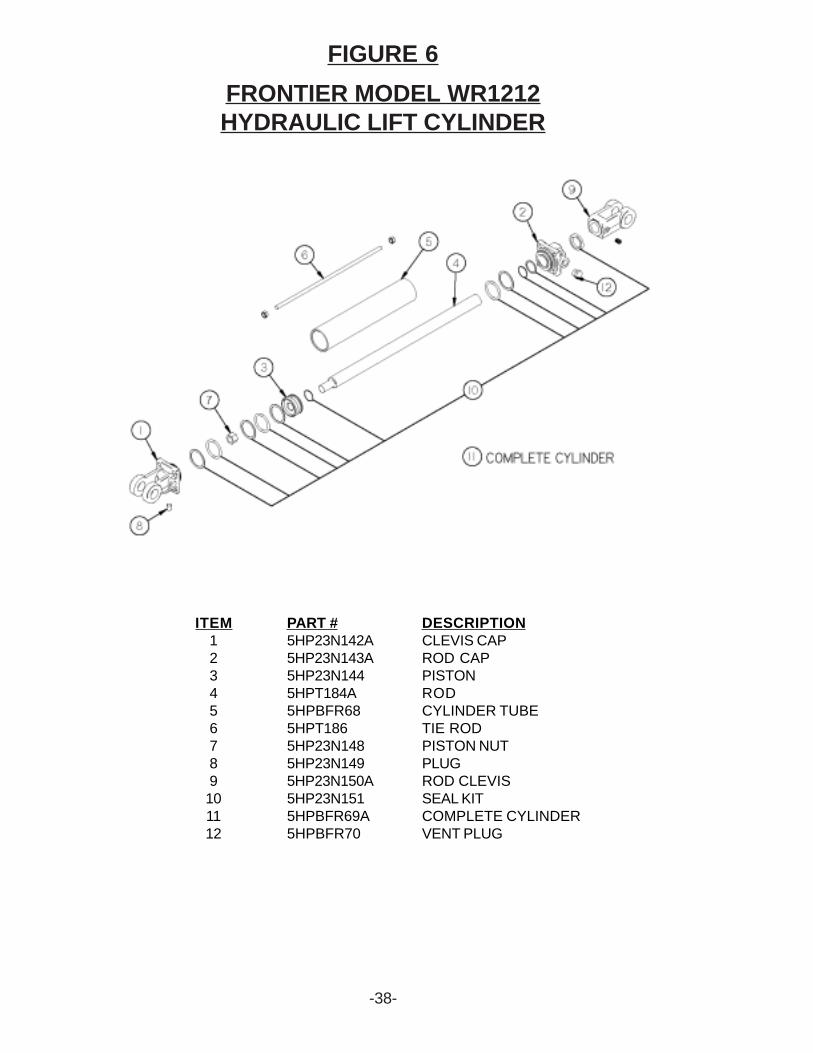
FIGURE 6
-38-
FRONTIER MODEL WR1212HYDRAULIC LIFT CYLINDER
ITEM123456789101112
PART #5HP23N142A5HP23N143A5HP23N1445HPT184A5HPBFR685HPT1865HP23N1485HP23N1495HP23N150A5HP23N1515HPBFR69A5HPBFR70
DESCRIPTIONCLEVIS CAPROD CAPPISTONRODCYLINDER TUBETIE RODPISTON NUTPLUGROD CLEVISSEAL KITCOMPLETE CYLINDERVENT PLUG
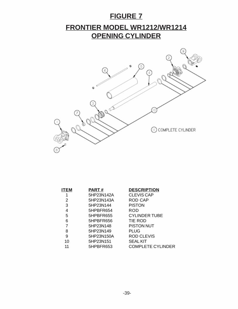
FIGURE 7
-39-
FRONTIER MODEL WR1212/WR1214OPENING CYLINDER
ITEM1234567891011
PART #5HP23N142A5HP23N143A5HP23N1445HPBFR6545HPBFR6555HPBFR6565HP23N1485HP23N1495HP23N150A5HP23N1515HPBFR653
DESCRIPTIONCLEVIS CAPROD CAPPISTONRODCYLINDER TUBETIE RODPISTON NUTPLUGROD CLEVISSEAL KITCOMPLETE CYLINDER
-40-
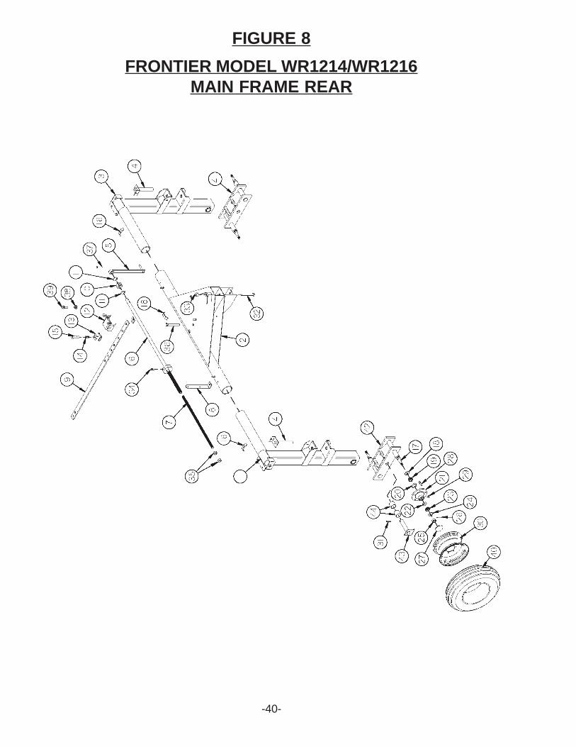
FIGURE 8FRONTIER MODEL WR1214/WR1216
MAIN FRAME REAR
FIGURE 8
-41-
NOTE: * (MEANS NOT SHOWN)
FRONTIER MODEL WR1214/WR1216MAIN FRAME REAR
ITEM1234567891011121314151617181920212223242526272829*
30313233343536373839
4041424344
PART #5HPBFR7545HPBFR7095HPBFR7555HPBFR7565HPBFR4235HPBFR4855HPBFR4205HPBFR6495HPBFR6115HPBFR4225HPBFR5235HPBFR6165HPBFR2395HPBFR2405HPBFR2415HP23N675HPBFR5225HPBFR575HP17G1455HP17G1465HPBFR605HPBFR615HPBFR625HPYWFL240055HPYNSL240105HPYPCT050105HPBFR665HPYBSD160055HPYNWL160055HPBFR755HPBFR675HPYPEX120255HPYBHH241155HPYNHX240105HPYBHH160105HPYNAC240055HPYBHH240905HPYBHH120905HPBFR6425HPYSHW10010
5HPBFR1285HPBFR5105HPBFR5095HPBFR5245HPBFR625
DESCRIPTIONRIGHT AXLE UPRIGHTREAR PIVOT ASSEMBLYLEFT AXLE UPRIGHTBEAM PIVOT SHAFTWIDTH ADJUSTMENT HANDLEREAR WIDTH ADJUSTMENT TUBEREAR WIDTH ADJUSTMENT RODSMV BRACKETWIDTH ADJUSTMENT BARWIDTH ADJUSTMENT COLLARPOLY WASHERWIDTH ADJUSTMENT STOPSLEEVE ADJUSTABLE LOCKSPRINGADJUSTMENT HANDLEHOSE HOLDERSPINDLESEALINNER BEARINGINNER RACEHUBOUTER RACEOUTER BEARINGWASHER, FLAT, 3/4" USSHEX NUT, SLOTTED, 3/4"-16COTTER PIN, 5/32" X 1-1/2"HUB CAPSTUD BOLT, 1/2"-20 UNF X 1-7/8" (3/8" SHOULDER)WHEEL NUT, 1/2"-20 UNFCOMPLETE HUB FOR GROUND WHEELWHEEL 5 X 15EXPANSION PIN, 3/8" X 2-3/4"BOLT, 3/4" X 8-1/2" GR. 5HEX NUT, 3/4"-16BOLT, 1/2" X 1" GR. 5HEX NUT, ACME, 3/4"-6BOLT, 3/4" X 6" GR. 5BOLT, 3/8" X 2-1/2" GR. 5WIDTH ADJUSTMENT SPACER5/16"-18 X 1-1/4" HEX WASHER SLOT TYPE F ZINCTHREAD CUTTING SCREWTIRE (6.70 X 15)LH TANDEM AXLERH TANDEM AXLETANDEM PINBUSHING
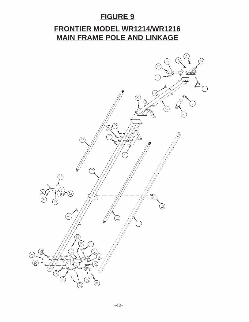
FIGURE 9
-42-
FRONTIER MODEL WR1214/WR1216MAIN FRAME POLE AND LINKAGE
FIGURE 9
NOTE: * (MEANS NOT SHOWN)
-43-
FRONTIER MODEL WR1214/WR1216MAIN FRAME POLE AND LINKAGE
ITEM12345*678910
*
*
11
*
*
12
*
1314151617181920212223242526272829303132
PART #5HPBFR4505HPBFR1575HPBFR7535HP12N1175HP5N785HP12N1185HPHE425HPBFR6635HPS5225HPS5235HP14DWE81
5HPBFR714
5HPBFR715
5HP14DCH07
5HPBFR711
5HPBFR710
5HP14DWE83
5HPBFR712
5HPBFR4585HPBFR4555HPBFR4565HPBFR4575HPBFR4655HPBFR4675HPBFR4685HPBFR4765HPBFR4795HPBFR4715HPBFR4915HPBFR4775HPBFR4805HPYPHR020105HPYPHR060405HPYBHH161655HPYBHH200255HPYNSL400055HPBFR5055HPBFR693
DESCRIPTIONHITCH PINHITCHJACKJACK PIN & CHAINJACK HANDLEREPLACEMENT BEARINGHOSE HOLDERPOLEMANUAL HOLDERMANUAL CLAMP - LARGEPOLE(STARTING SERIAL #0212123 FOR WR1214STARTING SERIAL #0213033 FOR WR1216 AND FOWARD)CENTER POLE(WR1214 SERIAL #0212121 ANDWR1216 SERIAL #0213032 AND PRIOR)BACK POLE(WR1214 Serial#0212122 AND WR1216Serial#0213032 AND PRIOR)POLE CHANNEL(Starting Serial#0212123 FOR WR1214)STARTING SERIAL #0213033 FOR WR1216 AND FOWARD)CENTER POLE BRACE(SERIAL #0212122 FOR WR1214SERIAL #0213032 FOR WR1216 AND PRIOR)BACK POLE BRACE(SERIAL #02120122 FOR WR1214SERIAL #0213032 FOR WR1216 AND PRIOR)MIDDLE LINKAGE STOP BOTTOM(STARITING SERIAL#0212123 FOR WR1214 AND STARTING SERIAL #0213033AND FOWARD)MIDDLE LINKAGE STOP(SERIAL #0212122 FOR WR1214SERAIL #0213032 FOR WR1216 AND PRIOR)FRONT LINKAGEFRONT LINKAGE SLIDERHOSE GUIDE SPACERSLIDER SPACERCENTER SLIDERCENTER SLIDER SPACERLINKAGE PINBACK LINKAGE YOKE RHPIVOT YOKE SHAFT PIN RHBACK SLIDER ROLLERBACK LINKAGE SLIDERBACK LINKAGE YOKE LHLEFT PIVOT YOKE SHAFTHAIR PIN, #21-07HAIR PIN, 3/16" X 3-3/4"BOLT, 1/2" X 6" GR. 5BOLT, 5/8" X 2" GR. 5HEX NUT, SLOTTED, 1-1/2"-12PIVOT YOKE SHAFT PIN LHSTOP WASHER

-44-
FIGURE 10FRONTIER MODEL WR1214/WR1216
RAKE BEAMS AND ARMS
-45-
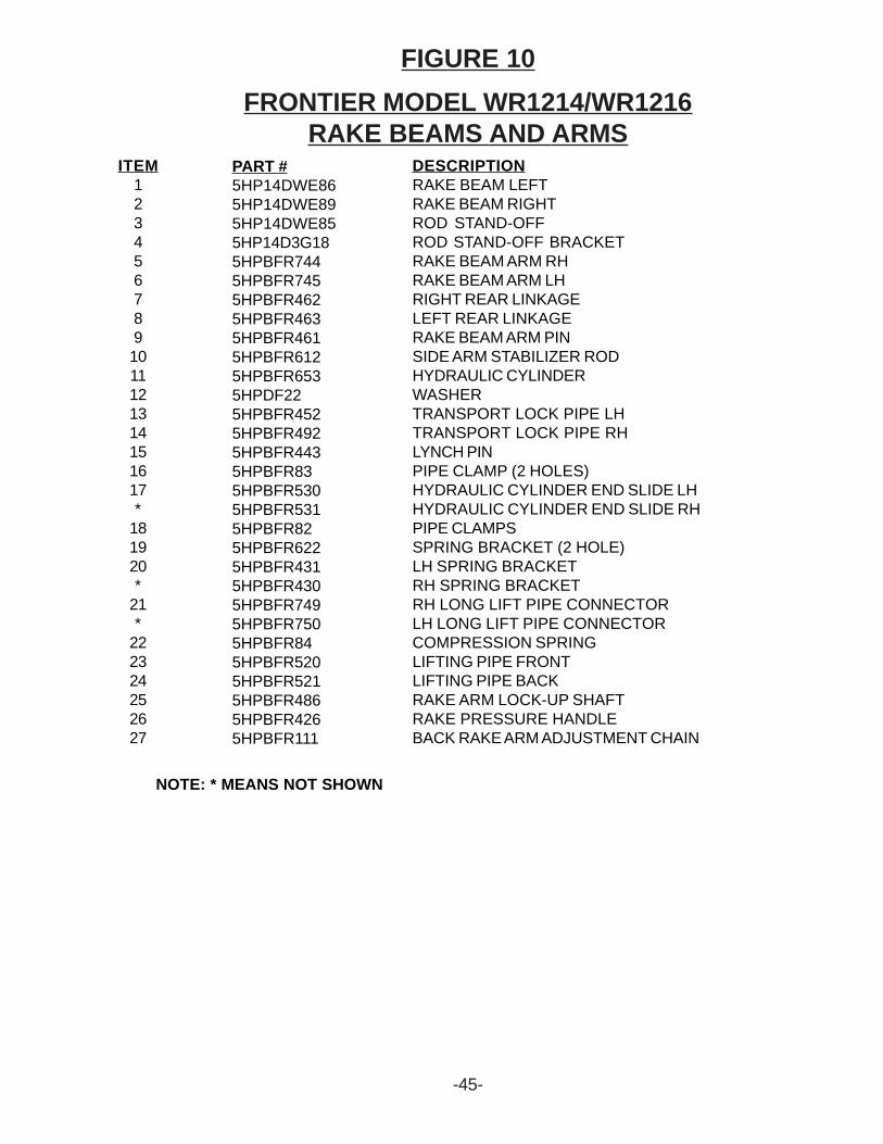
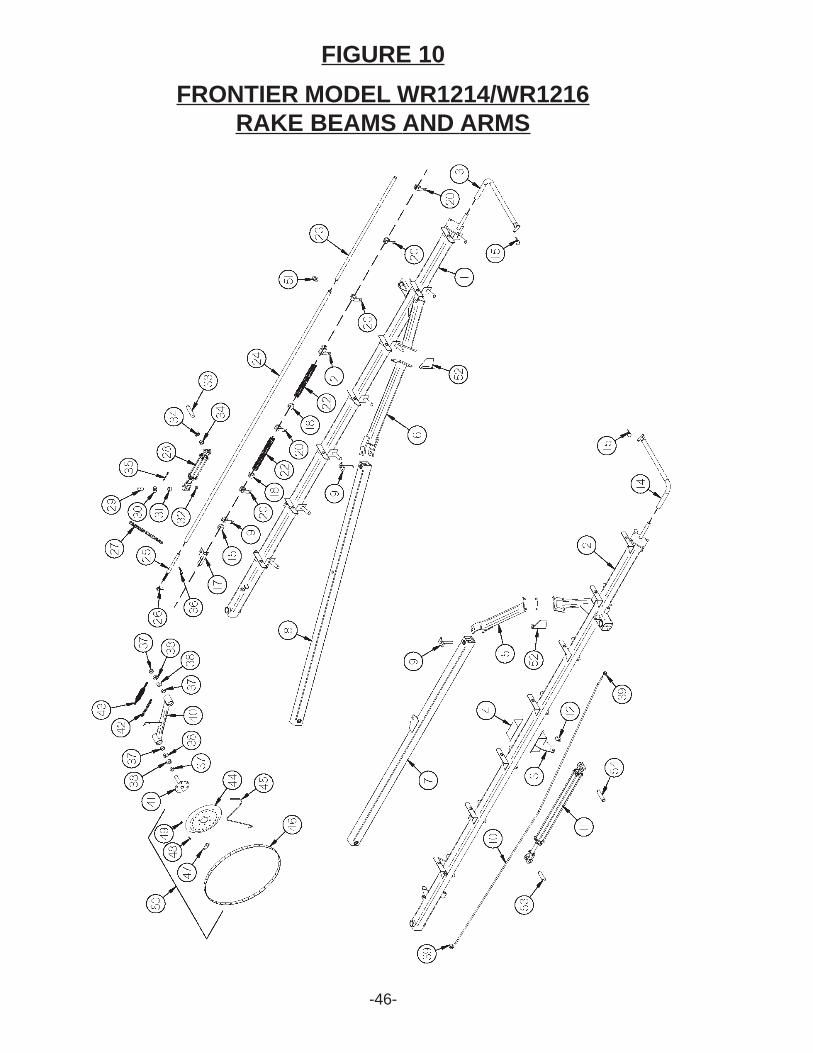
FIGURE 10FRONTIER MODEL WR1214/WR1216
RAKE BEAMS AND ARMSITEM
1234567891011121314151617*
181920*
21*
222324252627
PART #5HP14DWE865HP14DWE895HP14DWE855HP14D3G185HPBFR7445HPBFR7455HPBFR4625HPBFR4635HPBFR4615HPBFR6125HPBFR6535HPDF225HPBFR4525HPBFR4925HPBFR4435HPBFR835HPBFR5305HPBFR5315HPBFR825HPBFR6225HPBFR4315HPBFR4305HPBFR7495HPBFR7505HPBFR845HPBFR5205HPBFR5215HPBFR4865HPBFR4265HPBFR111
DESCRIPTIONRAKE BEAM LEFTRAKE BEAM RIGHTROD STAND-OFFROD STAND-OFF BRACKETRAKE BEAM ARM RHRAKE BEAM ARM LHRIGHT REAR LINKAGELEFT REAR LINKAGERAKE BEAM ARM PINSIDE ARM STABILIZER RODHYDRAULIC CYLINDERWASHERTRANSPORT LOCK PIPE LHTRANSPORT LOCK PIPE RHLYNCH PINPIPE CLAMP (2 HOLES)HYDRAULIC CYLINDER END SLIDE LHHYDRAULIC CYLINDER END SLIDE RHPIPE CLAMPSSPRING BRACKET (2 HOLE)LH SPRING BRACKETRH SPRING BRACKETRH LONG LIFT PIPE CONNECTORLH LONG LIFT PIPE CONNECTORCOMPRESSION SPRINGLIFTING PIPE FRONTLIFTING PIPE BACKRAKE ARM LOCK-UP SHAFTRAKE PRESSURE HANDLEBACK RAKE ARM ADJUSTMENT CHAIN
NOTE: * MEANS NOT SHOWN
-46-
FIGURE 10FRONTIER MODEL WR1214/WR1216
RAKE BEAMS AND ARMS
-47-
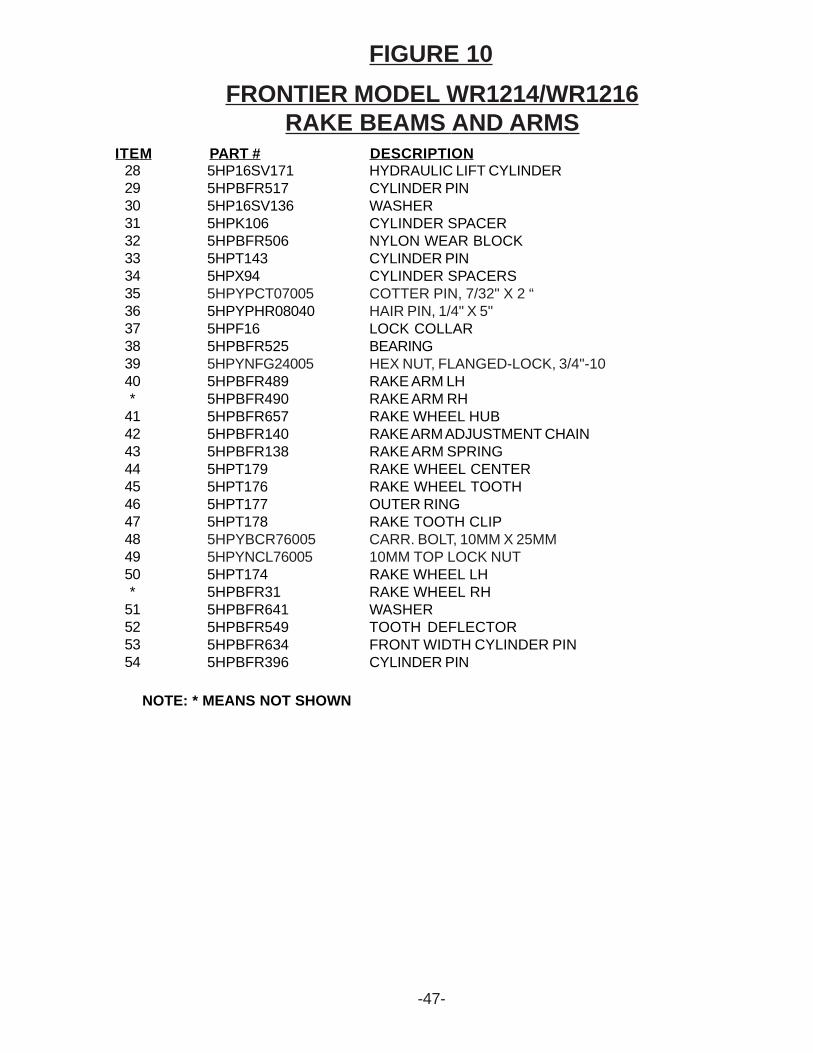
FIGURE 10FRONTIER MODEL WR1214/WR1216
RAKE BEAMS AND ARMS
28293031323334353637383940*
41424344454647484950*
51525354
5HP16SV1715HPBFR5175HP16SV1365HPK1065HPBFR5065HPT1435HPX945HPYPCT070055HPYPHR080405HPF165HPBFR5255HPYNFG240055HPBFR4895HPBFR4905HPBFR6575HPBFR1405HPBFR1385HPT1795HPT1765HPT1775HPT1785HPYBCR760055HPYNCL760055HPT1745HPBFR315HPBFR6415HPBFR5495HPBFR6345HPBFR396
HYDRAULIC LIFT CYLINDERCYLINDER PINWASHERCYLINDER SPACERNYLON WEAR BLOCKCYLINDER PINCYLINDER SPACERSCOTTER PIN, 7/32" X 2 “HAIR PIN, 1/4" X 5"LOCK COLLARBEARINGHEX NUT, FLANGED-LOCK, 3/4"-10RAKE ARM LHRAKE ARM RHRAKE WHEEL HUBRAKE ARM ADJUSTMENT CHAINRAKE ARM SPRINGRAKE WHEEL CENTERRAKE WHEEL TOOTHOUTER RINGRAKE TOOTH CLIPCARR. BOLT, 10MM X 25MM10MM TOP LOCK NUTRAKE WHEEL LHRAKE WHEEL RHWASHERTOOTH DEFLECTORFRONT WIDTH CYLINDER PINCYLINDER PIN
ITEM PART # DESCRIPTION
NOTE: * MEANS NOT SHOWN
-48-
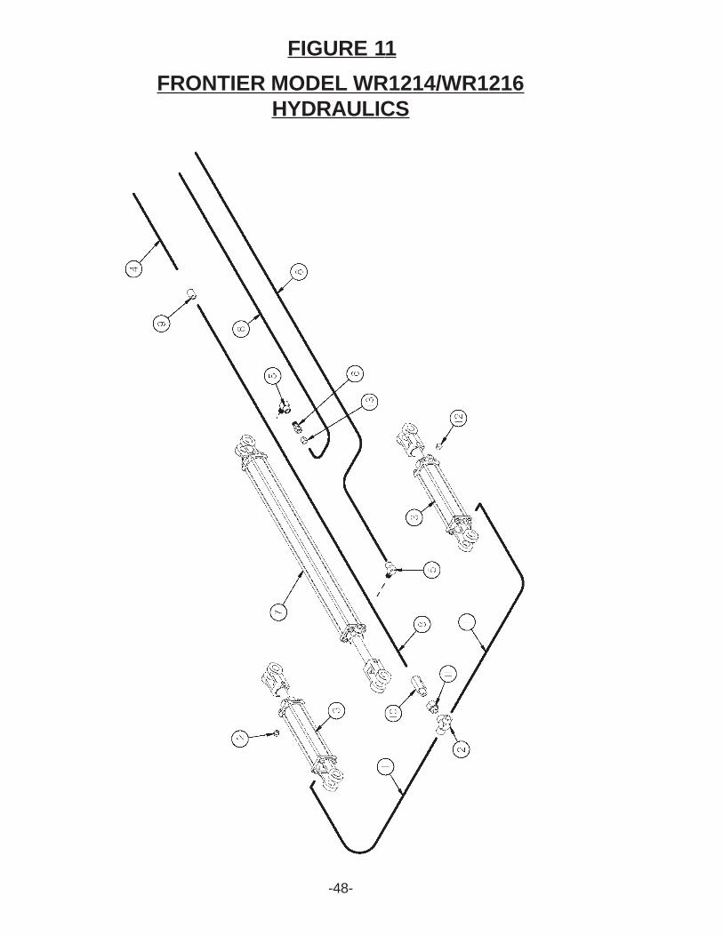
FIGURE 11FRONTIER MODEL WR1214/WR1216
HYDRAULICS
-49-
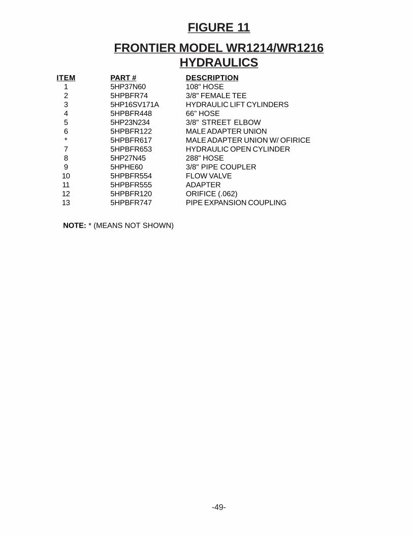
FIGURE 11FRONTIER MODEL WR1214/WR1216
HYDRAULICSITEM
123456*78910111213
PART #5HP37N605HPBFR745HP16SV171A5HPBFR4485HP23N2345HPBFR1225HPBFR6175HPBFR6535HP27N455HPHE605HPBFR5545HPBFR5555HPBFR1205HPBFR747
DESCRIPTION108" HOSE3/8" FEMALE TEEHYDRAULIC LIFT CYLINDERS66" HOSE3/8" STREET ELBOWMALE ADAPTER UNIONMALE ADAPTER UNION W/ OFIRICEHYDRAULIC OPEN CYLINDER288" HOSE3/8" PIPE COUPLERFLOW VALVEADAPTERORIFICE (.062)PIPE EXPANSION COUPLING
NOTE: * (MEANS NOT SHOWN)
-50-
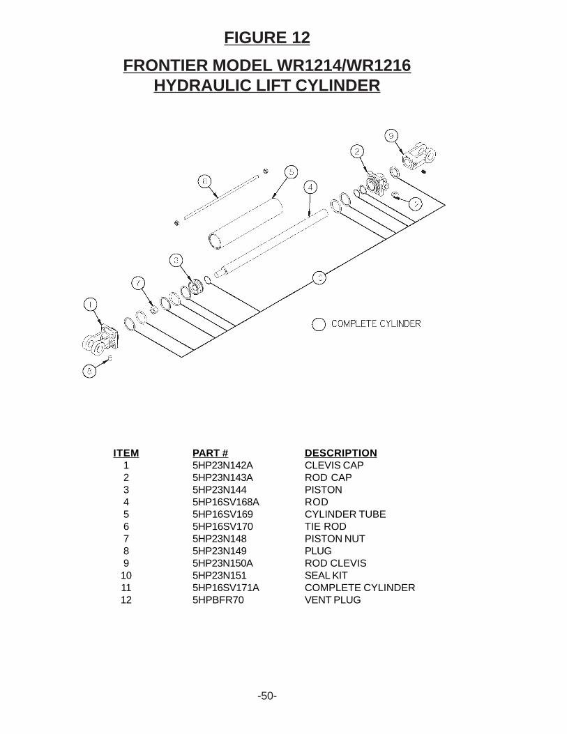
FIGURE 12FRONTIER MODEL WR1214/WR1216
HYDRAULIC LIFT CYLINDER
ITEM123456789101112
PART #5HP23N142A5HP23N143A5HP23N1445HP16SV168A5HP16SV1695HP16SV1705HP23N1485HP23N1495HP23N150A5HP23N1515HP16SV171A5HPBFR70
DESCRIPTIONCLEVIS CAPROD CAPPISTONRODCYLINDER TUBETIE RODPISTON NUTPLUGROD CLEVISSEAL KITCOMPLETE CYLINDERVENT PLUG
-51-
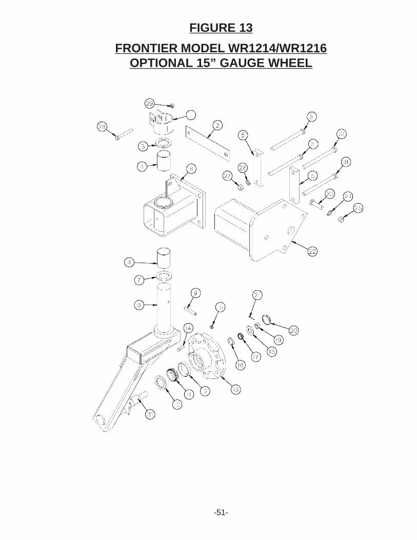
FIGURE 13FRONTIER MODEL WR1214/WR1216
OPTIONAL 15” GAUGE WHEEL
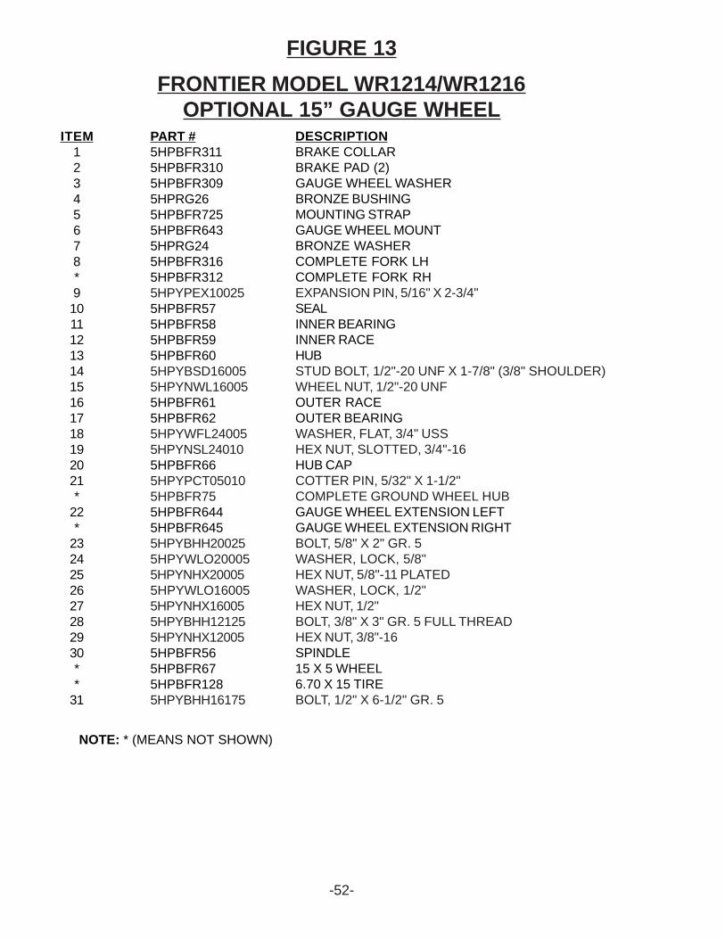
FRONTIER MODEL WR1214/WR1216OPTIONAL 15” GAUGE WHEEL
FIGURE 13
ITEM12345678*9101112131415161718192021*
22*
2324252627282930**
31
PART #5HPBFR3115HPBFR3105HPBFR3095HPRG265HPBFR7255HPBFR6435HPRG245HPBFR3165HPBFR3125HPYPEX100255HPBFR575HPBFR585HPBFR595HPBFR605HPYBSD160055HPYNWL160055HPBFR615HPBFR625HPYWFL240055HPYNSL240105HPBFR665HPYPCT050105HPBFR755HPBFR6445HPBFR6455HPYBHH200255HPYWLO200055HPYNHX200055HPYWLO160055HPYNHX160055HPYBHH121255HPYNHX120055HPBFR565HPBFR675HPBFR1285HPYBHH16175
DESCRIPTIONBRAKE COLLARBRAKE PAD (2)GAUGE WHEEL WASHERBRONZE BUSHINGMOUNTING STRAPGAUGE WHEEL MOUNTBRONZE WASHERCOMPLETE FORK LHCOMPLETE FORK RHEXPANSION PIN, 5/16" X 2-3/4"SEALINNER BEARINGINNER RACEHUBSTUD BOLT, 1/2"-20 UNF X 1-7/8" (3/8" SHOULDER)WHEEL NUT, 1/2"-20 UNFOUTER RACEOUTER BEARINGWASHER, FLAT, 3/4" USSHEX NUT, SLOTTED, 3/4"-16HUB CAPCOTTER PIN, 5/32" X 1-1/2"COMPLETE GROUND WHEEL HUBGAUGE WHEEL EXTENSION LEFTGAUGE WHEEL EXTENSION RIGHTBOLT, 5/8" X 2" GR. 5WASHER, LOCK, 5/8"HEX NUT, 5/8"-11 PLATEDWASHER, LOCK, 1/2"HEX NUT, 1/2"BOLT, 3/8" X 3" GR. 5 FULL THREADHEX NUT, 3/8"-16SPINDLE15 X 5 WHEEL6.70 X 15 TIREBOLT, 1/2" X 6-1/2" GR. 5
NOTE: * (MEANS NOT SHOWN)
-52-
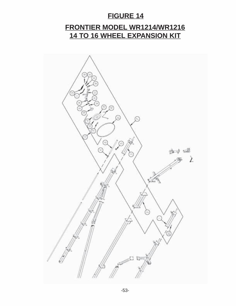
FIGURE 14FRONTIER MODEL WR1214/WR1216
14 TO 16 WHEEL EXPANSION KIT
-53-
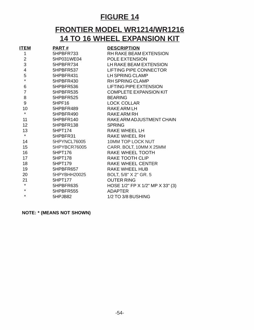
FRONTIER MODEL WR1214/WR121614 TO 16 WHEEL EXPANSION KIT
FIGURE 14
ITEM12345*678910*
111213*
1415161718192021***
PART #5HPBFR7335HP031WE045HPBFR7345HPBFR5375HPBFR4315HPBFR4305HPBFR5365HPBFR5355HPBFR5255HPF165HPBFR4895HPBFR4905HPBFR1405HPBFR1385HPT1745HPBFR315HPYNCL760055HPYBCR760055HPT1765HPT1785HPT1795HPBFR6575HPYBHH200255HPT1775HPBFR6355HPBFR5555HPJB82
DESCRIPTIONRH RAKE BEAM EXTENSIONPOLE EXTENSIONLH RAKE BEAM EXTENSIONLIFTING PIPE CONNECTORLH SPRING CLAMPRH SPRING CLAMPLIFTING PIPE EXTENSIONCOMPLETE EXPANSION KITBEARINGLOCK COLLARRAKE ARM LHRAKE ARM RHRAKE ARM ADJUSTMENT CHAINSPRINGRAKE WHEEL LHRAKE WHEEL RH10MM TOP LOCK NUTCARR. BOLT, 10MM X 25MMRAKE WHEEL TOOTHRAKE TOOTH CLIPRAKE WHEEL CENTERRAKE WHEEL HUBBOLT, 5/8" X 2" GR. 5OUTER RINGHOSE 1/2" FP X 1/2" MP X 33" (3)ADAPTER1/2 TO 3/8 BUSHING
NOTE: * (MEANS NOT SHOWN)
-54-
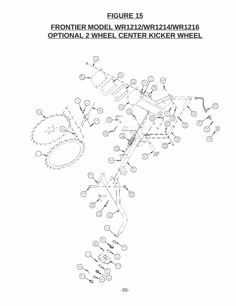
FIGURE 15FRONTIER MODEL WR1212/WR1214/WR1216
OPTIONAL 2 WHEEL CENTER KICKER WHEEL
-55-
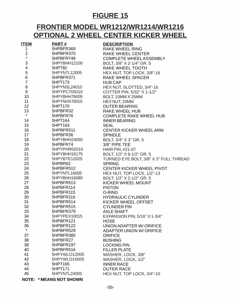
FRONTIER MODEL WR1212/WR1214/WR1216OPTIONAL 2 WHEEL CENTER KICKER WHEEL
FIGURE 15
ITEM12*345678910111213*
1415161718192021222324252627282930313233343536*
373839404142434445
PART #5HPBFR3695HPBFR3705HPBFR7485HPYBHH121005HPT825HPYNTL120055HPBFR3715HPT1735HPYNSL240105HPYPCT050105HPYBHH760055HPYNHX760155HPT1705HPBFR325HPBFR765HPT1645HPT1635HPBFR5115HPBFR365HPYBHH240505HPBFR745HPYPHR020105HPYBHH161755HPYBTE120255HPBR625HPBFR5125HPYNTL160055HPYBHH160805HPBFR5135HPBFR1145HPBFR1155HPBFR1165HPBFR5145HPBFR5155HPBFR3795HPYPEX100155HPBFR1215HPBFR1225HPBFR5295HPBFR3805HPBFR275HPBFR1975HPBFR5165HPYWLO120055HPYWLO160055HPT1655HPT1715HPYNTL24005
DESCRIPTIONRAKE WHEEL RINGRAKE WHEEL CENTERCOMPLETE WHEEL ASSEMBLYBOLT, 3/8" X 2-1/4" GR. 5RAKE WHEEL TOOTHHEX NUT, TOP LOCK, 3/8"-16RAKE WHEEL SPACERHUB CAPHEX NUT, SLOTTED, 3/4"-16COTTER PIN, 5/32" X 1-1/2"BOLT, 10MM X 25MMHEX NUT, 10MMOUTER BEARINGRAKE WHEEL HUBCOMPLETE RAKE WHEEL HUBINNER BEARINGSEALCENTER KICKER WHEEL ARMSPINDLEBOLT, 3/4" X 3" GR. 53/8" PIPE TEEHAIR PIN, #21-07BOLT, 1/2" X 6-1/2" GR. 5TURNED EYE BOLT, 3/8" X 3" FULL THREADSPRINGCENTER KICKER WHEEL PIVOTHEX NUT, TOP LOCK, 1/2"-13BOLT, 1/2" X 2-1/2" GR. 5KICKER WHEEL MOUNTPISTONO-RINGHYDRAULIC CYLINDERKICKER WHEEL OFFSETCYLINDER PINAXLE SHAFTEXPANSION PIN, 5/16" X 1-3/4"HOSEUNION ADAPTER W/ ORIFICEADAPTER UNION W/ ORIFICEORIFICEBUSHINGLOCKING PINFILLER PLATEWASHER, LOCK, 3/8"WASHER, LOCK, 1/2"INNER RACEOUTER RACEHEX NUT, TOP LOCK, 3/4"-10
NOTE: * MEANS NOT SHOWN
-56-
FRONTIER MODEL WR1212/WR1214/WR1216OPTIONAL 3 WHEEL CENTER KICKER WHEEL
FIGURE 16
-57-
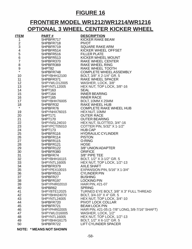
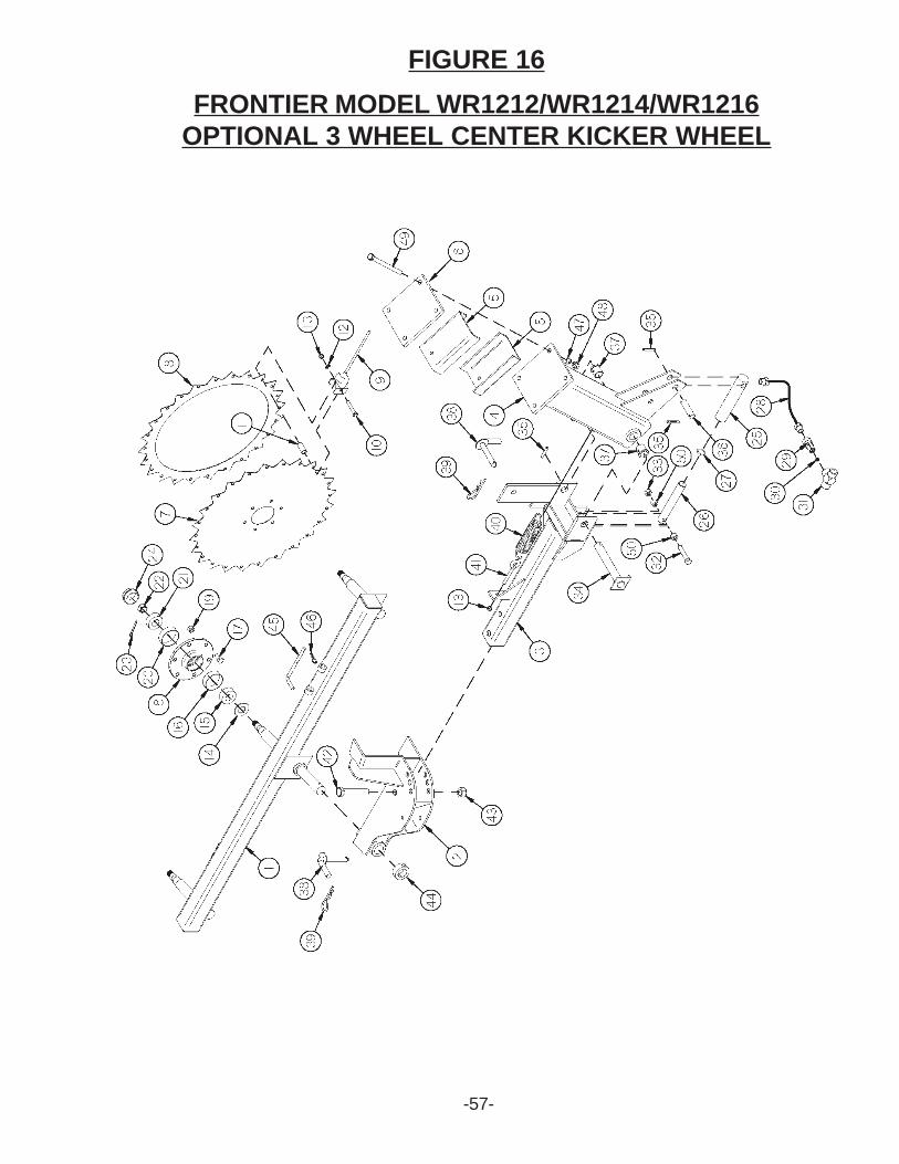
FRONTIER MODEL WR1212/WR1214/WR1216OPTIONAL 3 WHEEL CENTER KICKER WHEEL
FIGURE 16
ITEM123456789*
101112131415161718*
1920212223242526272829303132333435363738394041424344454647484950
PART #5HPBFR7175HPBFR7185HPBFR7195HPBFR5145HPBFR5165HPBFR5135HPBFR3705HPBFR3695HPT825HPBFR7485HPYBHH121005HPBFR3715HPYWLO120055HPYNTL120055HPT1635HPT1645HPT1655NPYBHH760055HPBFR325HPBFR765HPYNHX760155HPT1715HPT1705HPYNSL240105HPYPCT050105HPT1735HPBFR1165HPBFR1145HPBFR1155HPBFR1215HPBFR1225HPBFR3805HPBFR745HPYBHH161155HPYNTL160055HPBFR3795HPYPEX100155HPBFR5155HPBFR275HPBFR1975HPYPHR020105HPBR625HPYBTE120255HPYBHH240705HPYNTL240055HPBFR7205HPBFR7215HPYPHR020055HPYWLO160055HPYNTL160055HPYBHH161755HPBFR722
DESCRIPTIONKICKER RAKE BEAMPIVOTSQUARE RAKE ARMKICKER WHEEL OFFSETFILLER PLATEKICKER WHEEL MOUNTRAKE WHEEL CENTERRAKE WHEEL RINGRAKE WHEEL TOOTHCOMPLETE WHEEL ASSEMBLYBOLT, 3/8" X 2-1/4" GR. 5RAKE WHEEL SPACERWASHER, LOCK, 3/8"HEX NUT, TOP LOCK, 3/8"-16SEALINNER BEARINGINNER RACEBOLT, 10MM X 25MMRAKE WHEEL HUBCOMPLETE RAKE WHEEL HUBHEX NUT, 10MMOUTER RACEOUTER BEARINGHEX NUT, SLOTTED, 3/4"-16COTTER PIN, 5/32" X 1-1/2"HUB CAPHYDRAULIC CYLINDERPISTONO-RINGHOSE3/8" UNION ADAPTERORIFICE3/8" PIPE TEEBOLT, 1/2" X 3-1/2" GR. 5HEX NUT, TOP LOCK, 1/2"-13AXLE SHAFTEXPANSION PIN, 5/16" X 1-3/4"CYLINDER PINBUSHINGLOCKING PINHAIR PIN, #21-07SPRINGTURNED EYE BOLT, 3/8" X 3" FULL THREADBOLT, 3/4-10" X 4" GR. 5HEX NUT, TOP LOCK, 3/4"-10PIVOT LOCK COLLARBEAM LOCK PINHAIR PIN, #21-05 (1-7/8" LONG, 3/8-7/16" SHAFT)WASHER, LOCK, 1/2"HEX NUT, TOP LOCK, 1/2"-13BOLT, 1/2" X 6-1/2" GR. 5LIFT CYLINDER SPACER
NOTE: * MEANS NOT SHOWN
-58-
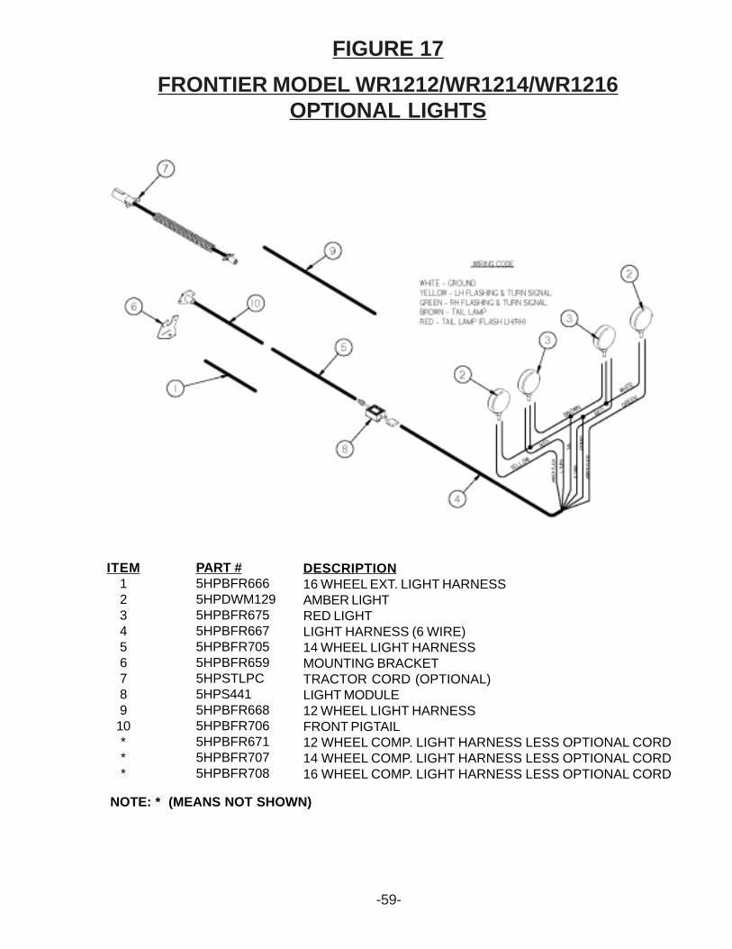
FIGURE 17FRONTIER MODEL WR1212/WR1214/WR1216
OPTIONAL LIGHTS
ITEM12345678910***
PART #5HPBFR6665HPDWM1295HPBFR6755HPBFR6675HPBFR7055HPBFR6595HPSTLPC5HPS4415HPBFR6685HPBFR7065HPBFR6715HPBFR7075HPBFR708
DESCRIPTION16 WHEEL EXT. LIGHT HARNESSAMBER LIGHTRED LIGHTLIGHT HARNESS (6 WIRE)14 WHEEL LIGHT HARNESSMOUNTING BRACKETTRACTOR CORD (OPTIONAL)LIGHT MODULE12 WHEEL LIGHT HARNESSFRONT PIGTAIL12 WHEEL COMP. LIGHT HARNESS LESS OPTIONAL CORD14 WHEEL COMP. LIGHT HARNESS LESS OPTIONAL CORD16 WHEEL COMP. LIGHT HARNESS LESS OPTIONAL CORD
NOTE: * (MEANS NOT SHOWN)
-59-

PARTS NOTES
-60-


Recommended