NetUP MultiMedia Processor.User’s manual
1
Contents1 Overview
NetUP MultiMedia Processor. . . . . . . . . . . . . . . . . . . . . . . . . . . . . . . . . . . . . . . . . . 2Supported formats and codecs . . . . . . . . . . . . . . . . . . . . . . . . . . . . . . . . . . . . . . . . 2
2 LCD panelIntroduction . . . . . . . . . . . . . . . . . . . . . . . . . . . . . . . . . . . . . . . . . . . . . . . . . . . . . . . 3Statistics screen. . . . . . . . . . . . . . . . . . . . . . . . . . . . . . . . . . . . . . . . . . . . . . . . . . . . 3Set IP address and subnet mask. . . . . . . . . . . . . . . . . . . . . . . . . . . . . . . . . . . . . . . 3Generate new administrator’s password . . . . . . . . . . . . . . . . . . . . . . . . . . . . . . . . . 4
3 Web interfaceOverview . . . . . . . . . . . . . . . . . . . . . . . . . . . . . . . . . . . . . . . . . . . . . . . . . . . . . . . . . 5IPTV. . . . . . . . . . . . . . . . . . . . . . . . . . . . . . . . . . . . . . . . . . . . . . . . . . . . . . . . . . . . . 5System administration . . . . . . . . . . . . . . . . . . . . . . . . . . . . . . . . . . . . . . . . . . . . . . . 7System configuration . . . . . . . . . . . . . . . . . . . . . . . . . . . . . . . . . . . . . . . . . . . . . . . . 8System status . . . . . . . . . . . . . . . . . . . . . . . . . . . . . . . . . . . . . . . . . . . . . . . . . . . . 10Video stream processing . . . . . . . . . . . . . . . . . . . . . . . . . . . . . . . . . . . . . . . . . . . . 11
2
Overview 2NetUP MultiMedia ProcessorNetUP MultiMedia Processor (транскодер) is a professional software solution for encoding and transcoding video streams in real time.
Please read the Web-interface chapter for the server settings and transcoding setup.
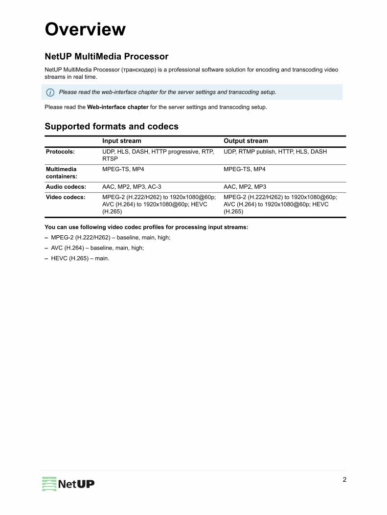
Supported formats and codecs
You can use following video codec profiles for processing input streams: – MPEG-2 (H.222/H262) – baseline, main, high;
– AVC (H.264) – baseline, main, high;
– HEVC (H.265) – main.
Please read the web-interface chapter for the server settings and transcoding setup.
Input stream Output streamProtocols: UDP, HLS, DASH, HTTP progressive, RTP,
RTSPUDP, RTMP publish, HTTP, HLS, DASH
Multimedia containers:
MPEG-TS, MP4 MPEG-TS, MP4
Audio codecs: AAC, MP2, MP3, AC-3 AAC, MP2, MP3
Video codecs: MPEG-2 (H.222/H262) to 1920x1080@60p; AVC (H.264) to 1920x1080@60p; HEVC (H.265)
MPEG-2 (H.222/H262) to 1920x1080@60p; AVC (H.264) to 1920x1080@60p; HEVC (H.265)
LCD panel 3IntroductionIn order to set up the NetUP’s server equipped with LCD panel, do the following: 1. Plug the network and power cables into the device.2. Switch power on. You shall see Startup... on the LCD panel.3. Use the LCD manager for the initial setup of the system.
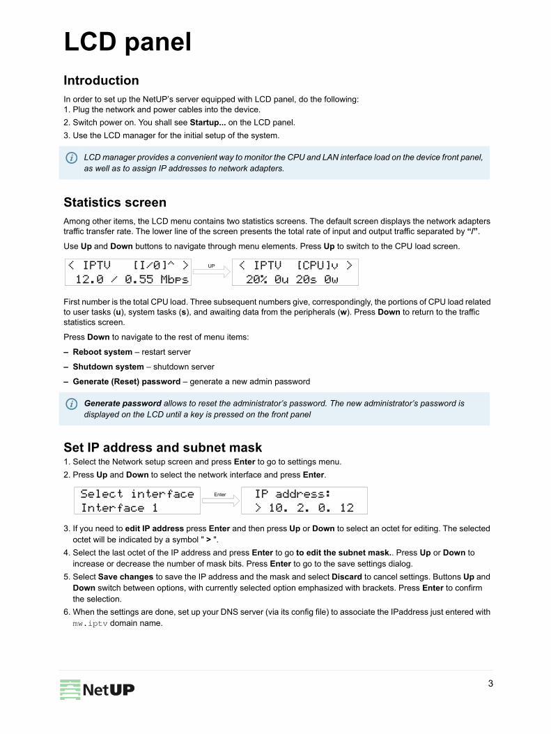
Statistics screenAmong other items, the LCD menu contains two statistics screens. The default screen displays the network adapters traffic transfer rate. The lower line of the screen presents the total rate of input and output traffic separated by “/”.
Use Up and Down buttons to navigate through menu elements. Press Up to switch to the CPU load screen.
First number is the total CPU load. Three subsequent numbers give, correspondingly, the portions of CPU load related to user tasks (u), system tasks (s), and awaiting data from the peripherals (w). Press Down to return to the traffic statistics screen.
Press Down to navigate to the rest of menu items:
– Reboot system – restart server
– Shutdown system – shutdown server
– Generate (Reset) password – generate a new admin password
Set IP address and subnet mask1. Select the Network setup screen and press Enter to go to settings menu.2. Press Up and Down to select the network interface and press Enter.
3. If you need to edit IP address press Enter and then press Up or Down to select an octet for editing. The selected octet will be indicated by a symbol " > ".
4. Select the last octet of the IP address and press Enter to go to edit the subnet mask.. Press Up or Down to increase or decrease the number of mask bits. Press Enter to go to the save settings dialog.
5. Select Save changes to save the IP address and the mask and select Discard to cancel settings. Buttons Up and Down switch between options, with currently selected option emphasized with brackets. Press Enter to confirm the selection.
6. When the settings are done, set up your DNS server (via its config file) to associate the IPaddress just entered with mw.iptv domain name.
LCD manager provides a convenient way to monitor the CPU and LAN interface load on the device front panel, as well as to assign IP addresses to network adapters.
Generate password allows to reset the administrator’s password. The new administrator’s password is displayed on the LCD until a key is pressed on the front panel
< IPTV [I/0]^ > 12.0 / 0.55 Mbps
< IPTV [CPU]v > 20% 0u 20s 0w
UP
Select interface Interface 1
IP address:> 10. 2. 0. 12
Enter
3
Generate new administrator’s password
Generate new administrator’s password1. Starting from the statistic screen, press Up until you see the Reset Password.2. Press Enter to generate new password and apply it to all system components. The password will be displayed on
the LCD screen.
4
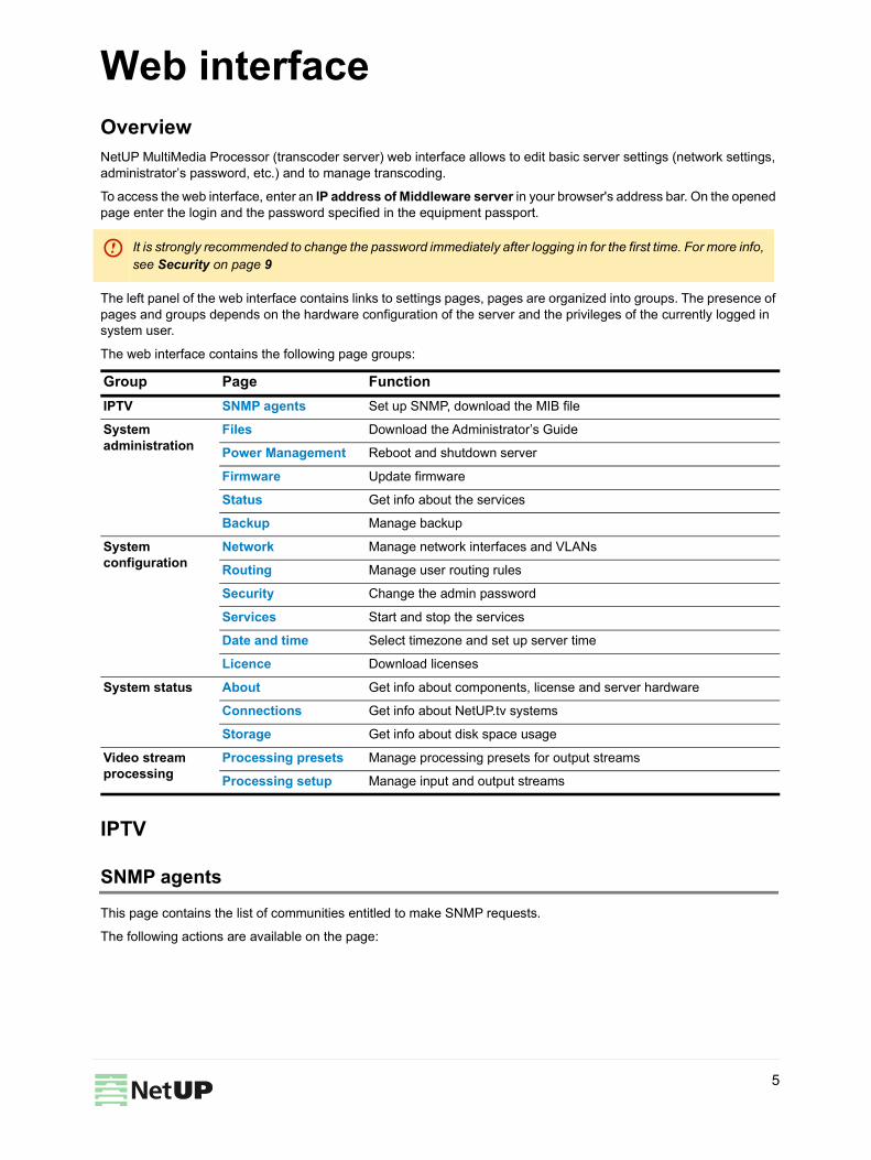
Web interface 4OverviewNetUP MultiMedia Processor (transcoder server) web interface allows to edit basic server settings (network settings, administrator’s password, etc.) and to manage transcoding.
To access the web interface, enter an IP address of Middleware server in your browser's address bar. On the opened page enter the login and the password specified in the equipment passport.
The left panel of the web interface contains links to settings pages, pages are organized into groups. The presence of pages and groups depends on the hardware configuration of the server and the privileges of the currently logged in system user.
The web interface contains the following page groups:
IPTV
SNMP agents
This page contains the list of communities entitled to make SNMP requests.
The following actions are available on the page:
It is strongly recommended to change the password immediately after logging in for the first time. For more info, see Security on page 9
Group Page FunctionIPTV SNMP agents Set up SNMP, download the MIB file
System administration
Files Download the Administrator’s Guide
Power Management Reboot and shutdown server
Firmware Update firmware
Status Get info about the services
Backup Manage backup
System configuration
Network Manage network interfaces and VLANs
Routing Manage user routing rules
Security Change the admin password
Services Start and stop the services
Date and time Select timezone and set up server time
Licence Download licenses
System status About Get info about components, license and server hardware
Connections Get info about NetUP.tv systems
Storage Get info about disk space usage
Video stream processing
Processing presets Manage processing presets for output streams
Processing setup Manage input and output streams
5
IPTV
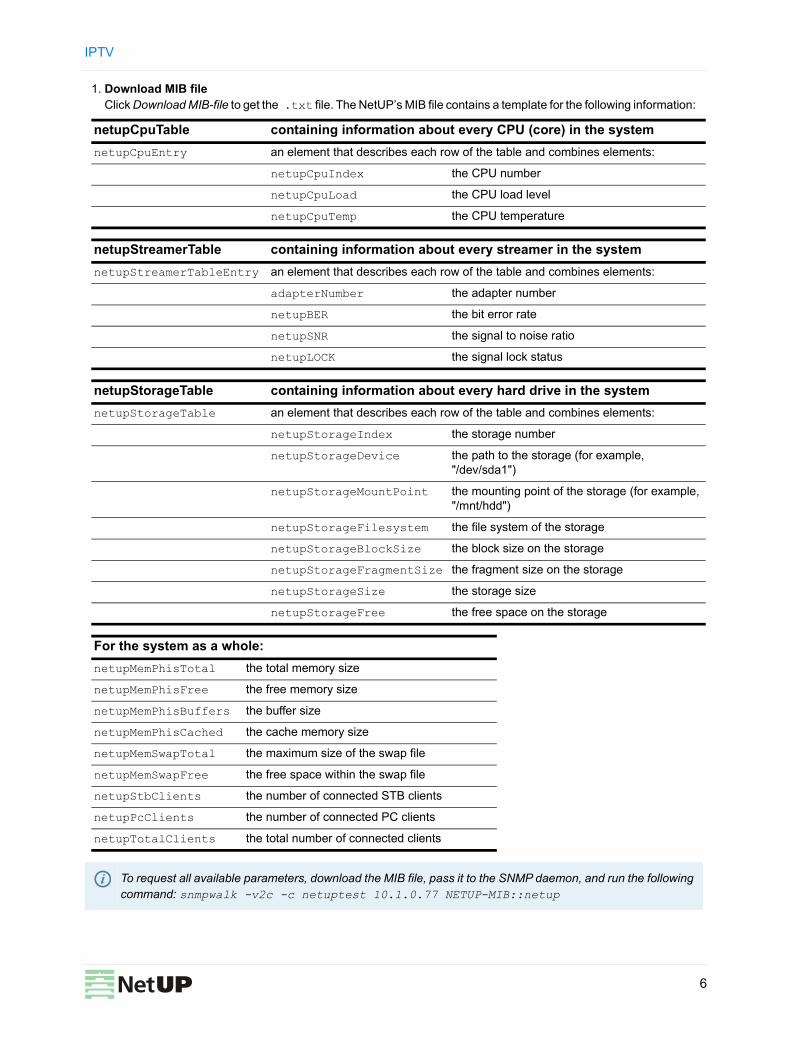
1. Download MIB file Click Download MIB-file to get the .txt file. The NetUP’s MIB file contains a template for the following information:
netupCpuTable containing information about every CPU (core) in the systemnetupCpuEntry an element that describes each row of the table and combines elements:
netupCpuIndex the CPU number
netupCpuLoad the CPU load level
netupCpuTemp the CPU temperature
netupStreamerTable containing information about every streamer in the systemnetupStreamerTableEntry an element that describes each row of the table and combines elements:
adapterNumber the adapter number
netupBER the bit error rate
netupSNR the signal to noise ratio
netupLOCK the signal lock status
netupStorageTable containing information about every hard drive in the systemnetupStorageTable an element that describes each row of the table and combines elements:
netupStorageIndex the storage number
netupStorageDevice the path to the storage (for example, "/dev/sda1")
netupStorageMountPoint the mounting point of the storage (for example, "/mnt/hdd")
netupStorageFilesystem the file system of the storage
netupStorageBlockSize the block size on the storage
netupStorageFragmentSize the fragment size on the storage
netupStorageSize the storage size
netupStorageFree the free space on the storage
For the system as a whole:netupMemPhisTotal the total memory size
netupMemPhisFree the free memory size
netupMemPhisBuffers the buffer size
netupMemPhisCached the cache memory size
netupMemSwapTotal the maximum size of the swap file
netupMemSwapFree the free space within the swap file
netupStbClients the number of connected STB clients
netupPcClients the number of connected PC clients
netupTotalClients the total number of connected clients
To request all available parameters, download the MIB file, pass it to the SNMP daemon, and run the following command: snmpwalk -v2c -c netuptest 10.1.0.77 NETUP-MIB::netup
6
System administration
2. Add an agent Click Add agent, then in the opened window, fill in the fields and click Save.
3. Edit parameters of a community or delete it Left-click on the community’s IP address. In the opened window make changes and click Save to apply them or click Delete to remove the community.
System administration
Files
Here you can download the “NetUP.tv Administrator's Guide” in Russian or English.
Power Management
Here you can Reboot and Shutdown the server. Whenever the server needs to be reloaded or shut down, this should be done exclusively by means of these controls; abnormal termination may lead to system failure.
Firmware
This page allows to update the IPTV server firmware. This page lists the uploaded firmware files together with their uploading dates, build numbers, and possible actions. Click a firmware to open detailed information popup: Delete or Install.Connect to the server via ftp (use login update and administrator’s password). Refresh the page, select the uploaded file from the list and click Install.
Status
The page displays:
– Backup – backup status;
– Timezone – selected timezone;
– Licence – license number and owner;
– Internet – Internet connection status;
– Server password – password for SSH and FTP connection;
– Status of adapters and system components – NetUP IPTV Core, Middleware, Billing, etc.;
– Connections between systems – connection presence.
Backup
The page contains the list of backups – .tar.bz2 archives that contain the system settings.
The following actions are available on the page:
Older firmware versions can be uploaded and will be shown in the list, but can't be installed
Using the corresponding button, you can collect diagnostic information about the services to send it to technical support
The page is present only on IPTV Core servers
7
System configuration
1. Create a backup manually Click Create to save an additional copy of system settings.
2. Delete, download a backup or restore system settings Left-click on an archive. In the opened window click one of the following buttons: Delete – remove the archive, Download – load the tar.bz2 archive, Restore backup – apply system settings from the archive.
System configuration
Network
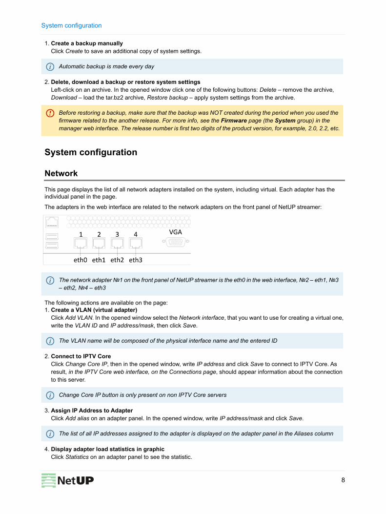
This page displays the list of all network adapters installed on the system, including virtual. Each adapter has the individual panel in the page.
The adapters in the web interface are related to the network adapters on the front panel of NetUP streamer:
The following actions are available on the page: 1. Create a VLAN (virtual adapter)
Click Add VLAN. In the opened window select the Network interface, that you want to use for creating a virtual one, write the VLAN ID and IP address/mask, then click Save.
2. Connect to IPTV Core Click Change Core IP, then in the opened window, write IP address and click Save to connect to IPTV Core. As result, in the IPTV Core web interface, on the Connections page, should appear information about the connection to this server.
3. Assign IP Address to Adapter Click Add alias on an adapter panel. In the opened window, write IP address/mask and click Save.
4. Display adapter load statistics in graphic Click Statistics on an adapter panel to see the statistic.
Automatic backup is made every day
Before restoring a backup, make sure that the backup was NOT created during the period when you used the firmware related to the another release. For more info, see the Firmware page (the System group) in the manager web interface. The release number is first two digits of the product version, for example, 2.0, 2.2, etc.
The network adapter №1 on the front panel of NetUP streamer is the eth0 in the web interface, №2 – eth1, №3 – eth2, №4 – eth3
The VLAN name will be composed of the physical interface name and the entered ID
Change Core IP button is only present on non IPTV Core servers
The list of all IP addresses assigned to the adapter is displayed on the adapter panel in the Aliases column
8
System configuration
5. Set the main interface Left-click on the IP address (Inet adress) of an adapter. In the opened window check the Main interface box and click Save.
6. Edit an IP-address or delete it Left-click on the IP address (Inet adress or Aliasses) you want to edit. In the opened window change the IP address and click Save. You cannot delete Main IP or the last remaining IP address of the adapter.
7. Change the IP addresses range served by the DHCP server Left-click on the IP addresses range in the DHCP server column on the panel of an adapter. In the opened window specify the required range and, if necessary, add static addresses, then click Save to apply changes.
8. Stop or start DHCP server Click UP / DOWN on the panel of an adapter. In the opened window click OK to switch the server.
9. Delete a VLAN Click Delete VLAN on the panel of an adapter. In the opened window click OK to delete the selected adapter.
Routing
This page displays User routing rules and System routing table.
The following actions are available on the page: 1. Add a user routing rule
Click Add rule, then in the opened window, write IP address/mask, Gateway, select Network interface and click Save.
2. Edit or delete a rule Left-click on a rule. In the opened window make changes and click Save to apply them or click Delete to remove the rule.
3. Show or hide the system routing table Click on the Show / Hide button.
Security
Use this page to change the access password.
The default main interface is eth0
The address assigned for the main interface is used for the component’s interaction and thus is absolutely crucial for the system’s operation. It can never be deleted
The UP / DOWN button is also the DHCP server status indicator
Automatic backup is made every day
The system routing table is needed for correct system operation
Server admin password is used for SSH and FTP access
9
System status
Services
This page displays the list of the system services and their statuses (started or stopped).
Date and time
Use this page to set the server date and time, and select timezone. These features are only available for the IPTV Core.
The following actions are available on the page: 1. Set time manually
Click Set time, then in the opened window write Date and Time, then click Save.2. Select timezone
Click Select. In the opened window, select timezone and click Save.
3. Add an NTP server Click Add. In the opened window write the address of an NTP server and click Save.
4. Delete an NTP server Left-click on the address of the server you want to remove and click Delete in the opened window.
Licence
This page displays information about uploaded licenses (components, numbers, expiration dates and restrictions). Use this page to upload new licenses.
System status
About
This page keeps info about the NetUP.tv system: product and firmware versions, build numbers of individual systems, information about the license and server hardware (CPU, memory, hard drives and network interfaces).
Left-click on a service name. In the opened window click Start or Stop to switch the service
Set the correct timezone before uploading the license (see Licence on page 10), otherwise the system may work incorrectly
For each NTP server, you can see a synchronization status: Filed – the last sync attempt has failed; SYNC – the sync has been performed successfully; Reserved – this time server has not been used yet.
Set the correct timezone before uploading the license (see Date and time on page 10)
Make sure the new license is fully compatible with the old one before uploading it
10
Video stream processing
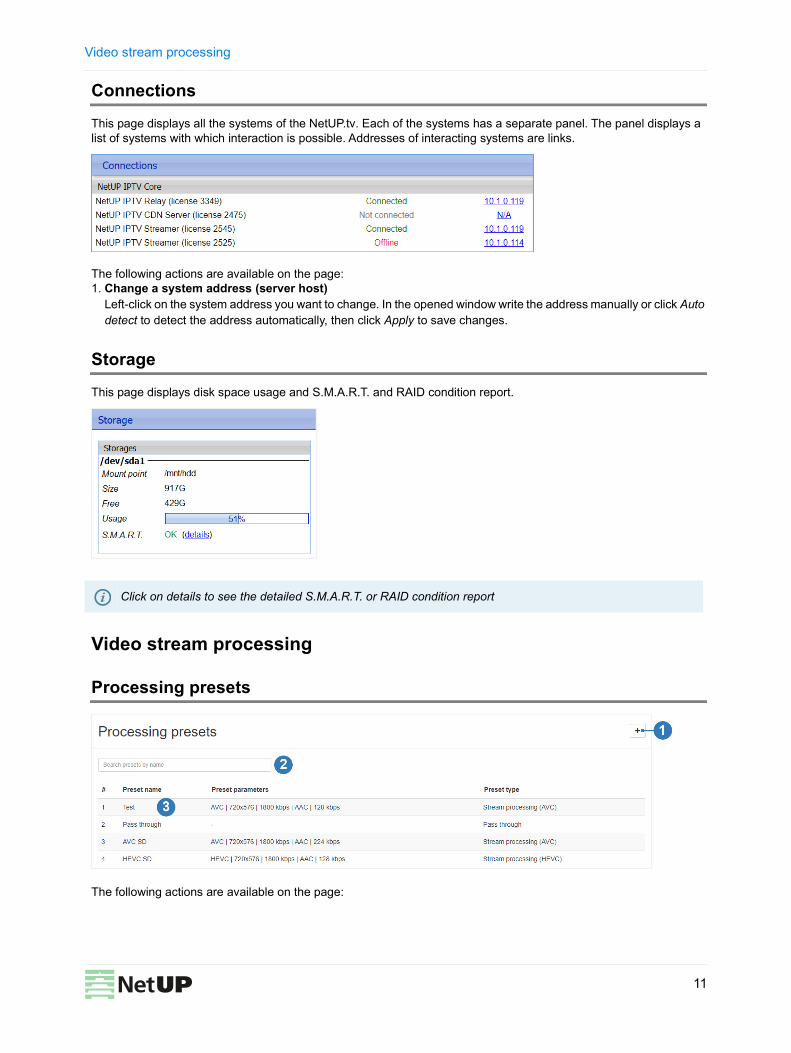
Connections
This page displays all the systems of the NetUP.tv. Each of the systems has a separate panel. The panel displays a list of systems with which interaction is possible. Addresses of interacting systems are links.
The following actions are available on the page: 1. Change a system address (server host)
Left-click on the system address you want to change. In the opened window write the address manually or click Auto detect to detect the address automatically, then click Apply to save changes.
Storage
This page displays disk space usage and S.M.A.R.T. and RAID condition report.
Video stream processing
Processing presets
The following actions are available on the page:
Click on details to see the detailed S.M.A.R.T. or RAID condition report
11

Video stream processing
1. Add a preset Click on the corresponding button on the page. In the opened window select processing parameters you want to store in the preset and click Save.
2. Find a preset Enter the preset name in the search bar and the search results will be displayed on the page.
3. Edit or delete a preset Left-click on the line with preset data you want to edit or delete. In the opened window change parameters and click Save or click Delete to remove the preset.
Processing setup
The following actions are available on the page: 1. Add input
Click on the corresponding button and select one of the options – from NetUP Streamer, from network video stream or from file. In the opened window, fill in the fields and click Save. After adding the stream, you automatically get to the Manage output streams page
2. Find an input Enter the input name in the search bar and the search results will be displayed on the page.
3. See a transcoder load The transcoder load is displayed in the upper right part of the page.
4. Copy an input or output address Click on the corresponding button next to a stream address. Data will be automatically copied to the clipboard.
Presets are classified into the following types: Pass through (pass the stream as is, without processing), Stream processing AVC, HEVC or MPEG-2. For all preset types except Pass through, you can configure video and audio processing parameters
You can not change the preset type
Changing parameters does not affect output streams that were configured using this processing preset. A set of preset settings is used only to quickly fill out web forms
Connect to the server via SSH and upload the video file to /netup/playlist/ before adding a stream from the file
12
Video stream processing
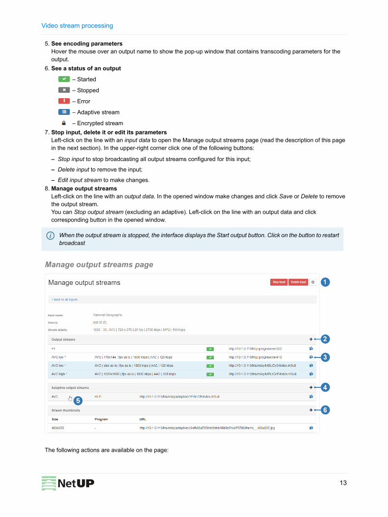
5. See encoding parameters Hover the mouse over an output name to show the pop-up window that contains transcoding parameters for the output.
6. See a status of an output
– Started
– Stopped
– Error
– Adaptive stream
– Encrypted stream7. Stop input, delete it or edit its parameters
Left-click on the line with an input data to open the Manage output streams page (read the description of this page in the next section). In the upper-right corner click one of the following buttons:
– Stop input to stop broadcasting all output streams configured for this input;
– Delete input to remove the input;
– Edit input stream to make changes.8. Manage output streams
Left-click on the line with an output data. In the opened window make changes and click Save or Delete to remove the output stream.You can Stop output stream (excluding an adaptive). Left-click on the line with an output data and click corresponding button in the opened window.
Manage output streams page
The following actions are available on the page:
When the output stream is stopped, the interface displays the Start output button. Click on the button to restart broadcast
13
Video stream processing
1. Stop an input, delete an input stream or edit its parameters Click on the corresponding button on the page to stop the input. If you stop the input, the broadcast of all output streams configured for this input will also be stopped.
Click on the corresponding button to delete the input stream and confirm the action in the opened window. Click Edit input stream to change its parameters, then make changes and click Save in the opened window.
2. Add an output stream Click on the corresponding button on the page. In the opened window fill in the fields and click Save. The new output will displayed on the Output streams panel.
3. Copy an output stream address Click on the corresponding button next to a stream address. Data will be automatically copied to the clipboard.
4. Add an adaptive output stream Click on the corresponding button on the page. In the opened window select streams you want to include in the adaptive stream, then click Save. The new adaptive stream will be displayed on the Adaptive output streams panel.
5. See the output streams included in an adaptive stream Hover the mouse over an adaptive stream and the streams that are included in it will be highlighted on the Output streams panel.
6. Add a thumbnails stream Click on the corresponding button on the page. In the opened window specify the Thumbnail size and click Save. The new thumbnails stream will be displayed on the Stream thumbnails panel.
7. Edit parameters of an output, delete or stop it Left-click on the line with an output data (including an adaptive and a thumbnails streams). In the opened window make changes and click Save or click Delete to remove the output stream.You can stop an output stream (excluding an adaptive and a thumbnails streams). Left-click on the line with an output data and click corresponding button in the opened window.
When the input is stopped, the interface displays the Start input button. Click on the button to restart input. Restarting the input, you are restoring the broadcast of all output streams that worked before the input was stopped
While adding the output stream, you can change processing settings on Video and Audio tabs. These changes do not affect the preset. Video and Audio tabs are available for all the preset types, except Pass through (pass the stream as is with no processing)
Before creating an adaptive stream, add the required number of output HLS streams which should be included in it. Use the corresponding button on the Output streams panel to add streams
The thumbnails with default size are used in the NetUP Android IP STB interface. Check the Use custom size option box and select the Thumbnail size from the drop-down list or select ‘Custom’ and enter a resolution
Thumbnails are used in the TV channels menu, in the STB interface. If you do not add the thumbnails stream for an input, the STB menu will display a TV channel logo
When the output stream is stopped, the interface displays the Start output button. Click on the button to restart broadcast
14
Video stream processing
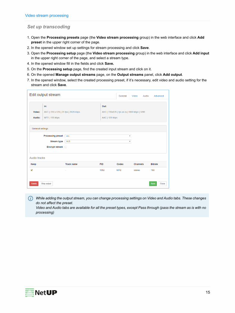
Set up transcoding
1. Open the Processing presets page (the Video stream processing group) in the web interface and click Add preset in the upper right corner of the page.
2. In the opened window set up settings for stream processing and click Save.3. Open the Processing setup page (the Video stream processing group) in the web interface and click Add input
in the upper right corner of the page, and select a stream type.4. In the opened window fill in the fields and click Save.5. On the Processing setup page, find the created input stream and click on it.6. On the opened Manage output streams page, on the Output streams panel, click Add output.7. In the opened window, select the created processing preset, if it’s necessary, edit video and audio setting for the
stream and click Save.
While adding the output stream, you can change processing settings on Video and Audio tabs. These changes do not affect the preset. Video and Audio tabs are available for all the preset types, except Pass through (pass the stream as is with no processing)
15

Current version of this document is distributed together with the NetUP.tv solution and is accessible via its web interface, see Files page
NetUP Inc. All rights reserved December 21, 2018
Phone: +7 495 510 1025
Address: Russia, Moscow, Ulofa Palme str. 1, sect. 7
Web: http://netup.tvE-mail: [email protected]
Recommended