OperationGuide MX100
Data Acquisition Unit
IM MX100-02E5th Edition

IM MX100-0E
User RegistrationThank you for purchasing YOKOGAWA products.
We invite you to register your products in order to receive the most up to date product information. To register, visit the following URL, or click the “Product Registration” button in the opening screen of the Manual CD-ROM.
http://www.yokogawa.com/ns/reg/
IM MX100-0E
Contents
Checking the Contents of the Package .......................................................................................................................5Function Introduction ...................................................................................................................................................9
Overview of the MX100 .............................................................................................................................................9Flow of Operation during Installation .......................................................................................................................10Function of the Modules ..........................................................................................................................................11Functions of the MX100 Standard Software ............................................................................................................14
Signal Wiring of the MX100 ........................................................................................................................................15Attachment Position and Channel Numbers of the Input/Output Module ................................................................15Terminal Arrangement Markings on the Terminal Cover ..........................................................................................15Wiring the Universal Input Module and DCV/TC/DI Input Module ...........................................................................16Wiring the Four-Wire RTD Resistance Input Modules .............................................................................................16Wiring the Strain Input Modules ...............................................................................................................................17Wiring the Digital Input Modules (-D05, -D24) .........................................................................................................21Wiring the Analog Output Modules ..........................................................................................................................22Wiring the PWM Output Modules ............................................................................................................................22Wiring the Digital Output Module .............................................................................................................................23
Connection to the Network .........................................................................................................................................4Connecting the Ethernet Cable to the Main Module ................................................................................................24Checking the Communication Status .......................................................................................................................24Connection to the PC ...............................................................................................................................................24
Setup Procedures of the MX100 Standard Software ................................................................................................5Installing the MX100 Standard Software .................................................................................................................25Installation Result ....................................................................................................................................................25
Operations of the MX100 Standard Software............................................................................................................6Connecting to or Disconnecting from the MX100 ....................................................................................................26Setting the Acquisition Conditions of the Measured Data ........................................................................................30Setting Measurement Conditions .............................................................................................................................32Monitoring the Measured Data and Setting the Display ..........................................................................................35Pausing the Updating of the Monitor Display and Reading Measured Values Using Cursors .................................40Recording the Measured Data .................................................................................................................................41Setting Alarms ..........................................................................................................................................................42Digital Output ...........................................................................................................................................................44Setting the Computation ..........................................................................................................................................46Saving/Loading and Printing of Setup Data (Project) ..............................................................................................46Displaying Recorded Measured Data, Reading Values Using Cursors, and Statistical Computation over an Area 48Printing the Displayed Data .....................................................................................................................................53Converting the Format of the Recorded Measured Data .........................................................................................53

4 IM MX100-0E
Thank you for purchasing the MX100 Data Acquisition Unit.This manual concisely describes the handling procedures of the MX100 Data Acquisition Unit (hereinafter the “MX100”) and basic operations on the MX100 Standard Software. To ensure correct use, please read this manual thoroughly before beginning operation.The five manuals below relating to the MX100 are provided in addition to this one. Read them along with this manual. Note that the MX100 Data Acquisition Unit User’s Manual (IM MX100-01E), this manual (IM MX100-02E), and the MX100 Standard Software User’s Manual (IM MX180-01E) are all available on the MX100 Manual CD-ROM.Manual Title Manual No. DescriptionMX100 Data Acquisition Unit User’s Manual
IM MX100-01E Describes the functions, installation, wiring procedures, handling precautions, and other information about the MX100.
Precautions on the Use of the MX100/ MW100 Data Acquisition Unit
IM MX100-71E Summarizes the usage precautions of the MX100/MW100.
MX100/MW100 Data Acquisition Unit Installation and Connection Guide
IM MX100-72E Describes concisely the installation and wiring procedures of the MX100/MW100.
Control of pollution caused by MX100/MW100 products
IM MX100-91C Describes control of pollution caused by the product.
MX100 Standard Software User’s Manual
IM MX180-01E Describes the functions and operations of the MX100 Standard Software that comes standard with the MX100 main module.
Notes• When configuring an MX100 system, the versions of the instruments used in the
system indicated by the hardware style number and software release number must meet the following conditions.• The main module style number must be greater than or equal to the style numbers
of any input/output modules.• The PC software release number must be greater than or equal to the style number
of the main module. Certain functions may become disabled on instruments or software that do not meet
these conditions, or the system may not be able to be built.• This manual describes the MX100 style number “S3,” and release number R3.03 of
the MX100 Standard Software. Check the style number on the name plate (see page 5 for the location of the name plate).
• Every effort has been made in the preparation of this manual to ensure the accuracy of its contents. However, should you have any questions or find any errors, please contact YOKOGAWA dealer.
• This operation guide does not cover the handling and operating procedures of Windows.
• Copying or reproducing all or any part of the contents of this manual without YOKOGAWA’s permission is strictly prohibited.
• The TCP/IP software of this product and the document concerning the TCP/IP software have been developed/created by YOKOGAWA based on the BSD Networking Software, Release 1 that has been licensed from California University.
Trademarks• DAQMASTER is a registered trademark of Yokogawa Electric Corporation.• Microsoft and Windows are registered trademarks or trademarks of Microsoft
Corporation in the United States and/or other countries.• Adobe and Acrobat are registered trademarks or trademarks of Adobe Systems
Incorporated.• Company and product names that appear in this manual are registered trademarks or
trademarks of their respective holders.• The company and product names used in this manual are not accompanied by the
registered trademark or trademark symbols (® and ™).
Revisions1st Edition: May, 2003 2nd Edition: November, 2004 3rd Edition: June, 20064th Edition: February, 2008 5th Edition: March, 2012
5th Edition: March 2012 (YK)All Rights Reserved, Copyright © 2003 Yokogawa Electric Corporation

5IM MX100-0E
Checking the Contents of the Package
Unpack the box and check the contents before operating the instrument. If some of the contents are not correct, or if any items are missing or damaged, contact the dealer from whom you purchased them.
Checking the Model and Suffix CodeCheck the model and suffix code on the name plate indicated in the figure below.
STY
LEM
OD
EL
MA
CNO
.
NO.SUFFIXSTYLE
MODEL
NO.SUFFIXSTYLE
MODEL
MO
DEL
NO.
Instrument numberSuffix code
ModelStyle number
Instrument number
Model/Suffix codeStyle numberMAC address
Main module Input/Output module
Base plate
Instrument numberModel
NoteWhen contacting the dealer from which you purchased the instrument, please give them the NO. (instrument number) on the name plate.
Main ModuleModel Suffix Code DescriptionMX100 MX100 main module
(comes with MX100 Standard Software)Language -E EnglishSupply voltage -1 100 VAC-240 VACPower supply and power cord
D 3-pin inlet, UL/CSA Standard power cord [Maximum rated voltage: 125 V; Maximum rated current: 7 A]
F 3-pin inlet, VDE Standard power cord [Maximum rated voltage: 250 V; Maximum rated current: 10 A]
R 3-pin inlet, AS Standard power cord [Maximum rated voltage: 240 V; Maximum rated current: 10 A]
Q 3-pin inlet, BS Standard power cord [Maximum rated voltage: 250 V; Maximum rated current: 10 A]
H 3-pin inlet, GB Standard power cord (complies with CCC) [Maximum rated voltage: 250 V; Maximum rated current: 10 A]
W Screw terminal (does not come with a power cord)Options /DS Dual Save function
/SL1* 10-CH Quick Start Package/SL2* 20-CH Quick Start Package/SL3* 30-CH Quick Start Package
* These can not be selected together. Shipped with the MX110-UNV-M10 and MX150 installed.

6 IM MX100-0E
Universal Input Module, DCV/TC/DI Input Module, and Four-Wire RTD Resistance Input Module
Model Suffix Code DescriptionMX110
Input type -UNV For DCV/TC/DI/3-wire RTD input-VTD For DCV/TC/DI input-V4R For DCV/DI/4-wire RTD/4-wire resistance input
Number of channels and measurement interval
-H04*1 4-CH, high-speed measurement (minimum measurement Interval: 10 ms)
-M06*1 6-CH, medium-speed measurement (minimum measurement interval: 100 ms)
-M10*1 10-CH, medium-speed measurement (minimum measurement interval: 100 ms)
-L30*1 30-CH, medium-speed measurement (minimum measurement interval: 500 ms)
Options /NC*2 Without the plate with the clamp terminals/H3*3 M3 screw terminals
*1 –H04 or –M10 must be selected if –UNV is selected. –M06 must be selected if –V4R is selected. -VTD must be selected if –L30 is selected.
*2 /NC can only be selected if –M10 is selected.*3 /H3 can only be selected if –L30 is selected.
Strain Input ModuleModel Suffix Code DescriptionMX112
Input type -B12 Internal bridge resistance: 120 Ω-B35 Internal bridge resistance: 350 Ω-NDI NDIS connector for connections to an external bridge head
Number of channels and measurement interval
-M04 4-CH, medium-speed measurement (minimum measurement interval: 100 ms)
Digital Input ModuleModel Suffix Code DescriptionMX115
Input type -D05 Non-voltage contact, 5-V logic, open collector input-D24 24 V logic
Number of channels and measurement interval
-H10 10-CH, high-speed measurement (minimum measurement interval: 10 ms)
Options /NC Without the plate with the clamp terminals
Analog Output ModuleModel Suffix Code DescriptionMX120
Output type -VAO Voltage/current output-PWM Pulse width modulation output
Number of channels and output update interval
-M08 8-CH, minimum output update interval: 100 ms
Digital Output ModuleModel Suffix Code DescriptionMX125
Output type -MKC A contact outputNumber of channels and output update interval
-M10 10-CH, minimum output update interval: 100 ms
Base PlateModel Suffix Code DescriptionMX150 Includes two brackets for DIN rail mount
Base type -1 to -6* The value of the suffix code corresponds to the maximum number of input/output modules that can be installed.MX150-6 is for one main module, and six input/output modules.
* One unit of the MX110-VTD-L30 requires three input/output modules’ worth of space when installing.
Checking the Contents of the Package

IM MX100-0E
Standard AccessoriesThe following standard accessories are supplied with the main module. Check that all contents are present and that they are undamaged.
*1 Not included when screw terminals are specified for the power section (Suffix code: W).
UL/CSA StandardA1074WD
VDE StandardA1009WD
BS StandardA1054WD
AS StandardA1024WD
D F QR
Power Cord (one of the following power cordsis supplied according to the instrument’s suffix codes)*1
H
GB Standard (complies with CCC)A1064WD
MX100 Standard SoftwareModel: MX180
• MX100 Data Acquisition Unit Operation Guide (This manual) (IM MX100-02E)• Precautions on the Use of the MX100/MW100 (IM MX100-71E)• MX100/MW100 Data Acquisition Unit Installation and Connection Guide (IM MX100-72E)• Control of pollution caused by MX100/MW100 products (IM MX100-91C)
MX100 Manual CD-ROM*2Part number: B8722XH
Paper Manuals
*2 • MX100 Data Acquisition Unit User’s Manual (IM MX100-01E)
• MX100 Data Acquisition Unit Operation Guide (This manual) (IM MX100-02E) • Contains the MX100 Standard Software User’s Manual (IM MX180-01E).
Optional Accessories (Sold Separately)TerminalsNo. Name Model Min. Q’ty Note1 10-CH screw terminal block
(with RJC)772061 1 Dedicated to the MX110-UNV-M10/
MX115-D05-H10/MX115-D24-H102 Connection cable between
the input module and screw terminal block
772062-050 1 Cable length: 50 cm*1
3 Connection cable between the input module and screw terminal block
772062-100 1 Cable length: 100 cm*1
4 Plate with clamp terminals (with RJC)
772063 1 Dedicated to the MX110-UNV-M10/MX115-D05-H10/MX115-D24-H10
5 Clamp terminal 772064 1 Dedicated to the MX110-UNV-H046 Clamp terminal 772065 1 Dedicated to the MX120-VAO-M08/
MX120-PWM-M08/MX125-MKC-M107 Connector cover 772066 1 For empty slots with no module
installed8 Plate with clamp terminals 772067 1 Dedicated to the MX110-V4R-M069 Plate with clamp terminals
(Built in bridge: 120 Ω)772068 1 Dedicated to the MX112-B12-M04*2
10 Plate with clamp terminals (Built in bridge: 350 Ω)
772069 1 Dedicated to the MX112-B35-M04*2
11 Plate with screw terminals (M3 screw, with RJC)
772080 1 Dedicated to the MX110-UNV-M10, MX115-D05-H10, and MX115-D24-H10
12 Plate with clamp terminals for current (Built in shunt resistor 10 Ω)
772081 1 Dedicated to the MX110-UNV-M10
13 Plate with clamp terminals for current (Built in shunt resistor 100 Ω)
772082 1 Dedicated to the MX110-UNV-M10
14 Plate with clamp terminals for current (Built in shunt resistor 250 Ω)
772083 1 Dedicated to the MX110-UNV-M10
*1 772062 is only applicable between the MX110-UNV-M10 and the screw terminal block (772061), the MX115-D05-H10 and the screw terminal block (772061), and the MX115-D24-H10 and the screw terminal block (772061).
*2 772068 is only applicable to MX112-B35-M04. 772069 is only applicable to MX112-B12-M04.
Checking the Contents of the Package

IM MX100-0E
2, 31 54 6 7
8 9 1110 12 13 14
Shunt ResistorsNo. Name Model Min. Q’ty Note15 Shunt resistor
(for the clamp terminal)438920 1 Resistance: 250 Ω ±0.1%
16 Shunt resistor (for the clamp terminal)
438921 1 Resistance: 100 Ω ±0.1%
17 Shunt resistor (for the clamp terminal)
438922 1 Resistance: 10 Ω ±0.1%
18 Shunt resistor 415920 1 Resistance: 250 Ω ±0.1%19 Shunt resistor 415921 1 Resistance: 100 Ω ±0.1%20 Shunt resistor 415922 1 Resistance: 10 Ω ±0.1%
Memory cardsNo. Name Model Min. Q’ty Note21 Adapter for compact flash
card772090 1 Adapter for inserting into PC card slot
22 Compact Flash card* 772093 1 512 MB23 Compact Flash card* 772094 1 1 GB24 Compact Flash card* 772095 1 2 GB* Operating temperature range: –40 to 85°C
Application Software (Sold Separately)No. Name Model Note1 MXLOGGER WX103 Data acquisition software for the MX100.2 GateMX/MW WX1 MX100/MW100 Gate software for connecting to
DAQLOGGER data acquisition software.
API (Sold Separately)No. Name Model Note1 API for the MX100/DARWIN MX190 Provides an API and extended API for the
MX100 and DARWIN.
MX100 Style Upgrade Kit* (Sold separately)No. Name Model Note1 MX100 Style Upgrade Kit 772050-01 Updates the old style of the MX100 main module
to the latest style.2 MX100 Style Upgrade Kit
(with the /DS option)772050-03 Updates the old style of the MX100 main module
with the Dual Save function (/DS option) to the latest style.
* Cannot be used with the special specification MX100 main module.
Checking the Contents of the Package

9IM MX100-0E
Function Introduction
For further details on each function, see the MX100 Data Acquisition Unit User’s Manual (IM MX100-01E) and the MX100 Standard Software User’s Manual (IM MX180-01E) provided on the accompanying CD-ROM.
Overview of the MX100The MX100 consists of the main module equipped with an Ethernet port, input/output modules that perform input or output of signals, and the base plate that attaches and connects all of these. The main module and the PC is connected locally via the Ethernet interface in a one-to-one relationship. By installing the MX100 Standard Software into the PC, you can use the PC to configure the acquisition conditions of the measured data of the MX100 and monitor or retrieve the measured data. The MX100 Standard Software allows a single PC to connect to a single MX100 unit (up to 60 channels in terms of the number of input channels). MXLOGGER, a software program sold separately, allows one to 20 PCs to connect to a single MX100 unit (up to 1200 channels in terms of the number of input channels).
One-to-one connection
MX100
• MX100 Standard Software• MXLOGGER (sold separately)• Software created using the API for the MX100/DARWIN (sold separately)
Hub
MX100
Input/Output module Main module
Base plate
Ethernet port
PC
One-to-N connection
MX100
MX100
MX100
Connect upto 20 units
Hub
MX100
• MXLOGGER (sold separately)• Software created using the API for the MX100/DARWIN (sold separately)
PC

10 IM MX100-0E
Flow of Operation during InstallationThe figure below shows the general flow of operation when the MX100 is installed initially.
Wire the input/outputmodules
Operations on the MX100 Operations on the PC
Connect the network cable
Connect thepower cable
Turn ON thepower switch
Set up the MX100Standard Software
Set the networkparameters of the PC
Start the IntegrationMonitor
Set the networkparameters of the MX100
Connect tothe network
Connect the MX100 Monitor screen display
Set the acquisitionconditions
Set the measurementconditions
Monitor themeasured data
Change thedisplay conditions
Record themeasured data
Start the Viewer
Install the MX100
Display therecorded data
See the Installation and Connection Guide*.
See the Installation and Connection Guide*.(For a simple description ofthe signal wiring,see pages 15 to 23.)
Page 24
See the Installation and Connection Guide*.
See the Installation and Connection Guide*.
* MX100/MW100 Data Acquisition Unit Installation and Connection Guide (IM MX100-72E)
Page 25
Page 24
Pages 26 to 29
Pages 30 and 31Set the monitor/record interval, recordstart/stop conditions, etc.
Pages 32 to 34Set the input mode, measurementrange, measurement span, etc.
Pages 37 to 41Pages 35 and 36
Page 41
Pages 48 to 53
This Operation Guide and the Installation andConnection Guide are abridged manuals.They do not cover all the functions and operations.They also do not cover the details of the precautionsand limitations of usage.For a detailed explanation, see the following electronicmanuals contained in the manual CD-ROM.• The functions, installation, wiring, and handling procedures
MX100 Data Acquisition Unit User’s Manual (IM MX100-01E)• The functions and operations of the MX100 Standard Software
MX100 Standard Software User’s Manual (IM MX180-01E)
Function Introduction

11IM MX100-0E
Function of the ModulesMain ModuleThe main module is equipped with a power supply connector, a power switch, an Ethernet port, a CF card slot, a 7-segment LED, dipswitches and other parts. It contains functions such as the power supply to and the control of each input/output module, communications with a PC, data storage to the CF card when communication is disconnected.
Ethernet port
Power switchCF cardslot
Power connector or screw terminal
7-segment LED
Dipswitch*
DATA ACQUISITION UNIT
ETHERNET
POWER10BASE - T
100BASE - TX
100 - 240V AC
Do
not o
pera
te w
ithou
t rea
ding
saf
ety
prec
autio
n in
use
rs m
anua
l.
70VA MAX50/60Hz
SW ON
1 2 3 4 5 6 7 8
Functional ground terminal
* Normally, turn all switches ON. Used to enable the /DS option functions, initialize settings, and perform other functions.
1 2 3 4 5 6 7 8
ON
Input/Output ModulesThe following twelve types of modules are available.
• 4-CH, High-Speed Universal Input Module (MX110-UNV-H04)
• Minimum measurement interval: 10 ms• Maximum number of inputs: 4 inputs• Input types: DC voltage, TC, 3-wire RTD, and DI (LEVEL,
non-voltage contact)
• 10-CH, Medium-Speed Universal Input Module (MX110-UNV-M10)
• Minimum measurement interval: 100 ms• Maximum number of inputs: 10 inputs• Input types: DC voltage, TC, 3-wire RTD, and DI (LEVEL,
non-voltage contact)
• 30-CH, Medium-Speed DCV/TC/DI Input Module (MX110-VTD-L30)
• Minimum measurement interval: 500 ms• Maximum number of inputs: 30 inputs• Input types: DC voltage, TC, and DI (LEVEL, non-voltage contact)
For MX110-VTD-L30/H3For MX110-VTD-L30
Function Introduction

1 IM MX100-0E
• 6-CH, Medium-Speed 4-Wire RTD Resistance Input Module (MX110-V4R-M06)
• Minimum measurement interval: 100 ms• Maximum number of inputs: 6 inputs• Input types: DC voltage, 4-wire RTD, 4-wire resistance,
and DI (LEVEL, non-voltage contact)
• 4-CH, Medium-Speed Strain Input Module (MX112-B12-M04, MX112-B35-M04)
• Minimum measurement interval: 100 ms• Maximum number of inputs: 4 inputs• Input system: floating balanced input (isolation between channels)
• 4-CH, Medium-Speed Strain Input Module (MX112-NDI-M04)
• Minimum measurement interval: 100 ms• Maximum number of inputs: 4 inputs• Input system: floating balanced input
(non-isolation between channels)
• 10-CH, High-Speed Digital Input Module (MX115-D05-H10)
• Minimum measurement interval: 10 ms• Maximum number of inputs: 10 inputs• Input types: DI (non-voltage contact, open collector, 5-V logic)
• 10-CH, High-Speed Digital Input Module (MX115-D24-H10)
• Minimum measurement interval: 10 ms• Maximum number of inputs: 10 inputs• Input types: DI (24-V logic)
The 10-CH, Pulse Input Module (MX114-PSL-M10) cannot be used with the MX100. For details see “Input/Output Modules” in section 1.1 of the MX100 Data Acquisition Unit User’s Manual (IM MX100-01E).
Function Introduction

1IM MX100-0E
• 8-CH, Medium-Speed Analog Output Module (MX120-VAO-M08)
• Output update interval: 100 ms (shortest)• Maximum number of outputs: 8 outputs• Output type: DC voltage, DC current
• 8-CH, Medium-Speed PWM Output Module (MX120-PWM-M08)
• Output update interval: 100 ms (shortest)• Maximum number of outputs: 8 outputs• Output type: PWM
• 10-CH, Medium-Speed Digital Output Module (MX125-MKC-M10)
• Output update interval: 100 ms (shortest)• Maximum number of outputs: 10 outputs• Output type: A contact (SPST)
Function Introduction

14 IM MX100-0E
Functions of the MX100 Standard SoftwareThe MX100 Standard Software consists of the three software programs below.
Integration MonitorEnables you to connect or disconnect communications, configure acquisition conditions and display conditions of the measured channels, set up computations, monitor measured and computed data, save measured and computed data, and carry out other operations.
ViewerEnables you to display measured and computed data that has been saved, read values and perform statistical computation over an area using cursors, and convert the measured and computed data into various file formats such as Excel.
CalibratorThis program is used to calibrate the input modules and output modules of the MX100. This operation guide does not cover the operating procedures of the software. See the MX100 Standard Software User’s Manual (IM MX180-01E).
Function Introduction

15IM MX100-0E
Signal Wiring of the MX100
For a description of the installation procedure, module attachment procedure, signal wiring details, and wiring of the power supply, see the MX100/MW100 Data Acquisition Installation and Connection Guide (IM MX100-72E) or the MX100 Data Acquisition Unit User’s Manual (IM MX100-01E). For the safety precautions, see the Precautions on the Use of the MX100/MW100 Data Acquisition Unit (IM MX100-71E) or the MX100 Data Acquisition Unit User’s Manual (IM MX100-01E).
Attachment Position and Channel Numbers of the Input/Output ModuleThe figure below shows how the MX100 Standard Software identifies the channel numbers.
MX100
012345 Slot number
001 to 010011 to 020
021 to 030031 to 040
041 to 050051 to 060 Channel number in the unit*2
Representation of channel numbers:Channel numbers in a unit (001 to 060)Unit number (00 to 19)*1
*2 The last one digit on a 4-channel module is 1 to 4. The last one digit on a 6-channel module is 1 to 6. The last one digit on a 8-channel module is 1 to 8.
*1 When connecting to the module using the MX100 Standard Software, the number is fixed to 00.
Terminal Arrangement Markings on the Terminal CoverOn the rear side of the terminal cover of each input/output module are characters that indicate the functions of the terminals and terminal symbols. Connect the wires according to the markings. The figure below is an example only.
100Vpk MAX TO250V MAX CH TO CH600V MAX TO
100Vpk MAX TO120V MAX CH TO CH600V MAX TO
250V MAX CH TO CH250V MAX NO TO C
250V MAX TO
10Vpk MAX TO
250V MAX TO
4-CH, High-SpeedUniversal Input Module
10-CH, Medium-SpeedUniversal Input Module
10-CH, High-SpeedDigital Input Module
Channel numberin the moduleTerminal symbol
10-CH, Medium-SpeedDigital Output Module
Terminal cover

16 IM MX100-0E
Wiring the Universal Input Module and DCV/TC/DI Input Module
• Thermocouple input • RTD input
Lead wire resistance per wire of 10 Ω or less*. Make the resistance of the three wires equal.
A plate with clamp terminals for current with built-in shunt resistance can be attached to the 10-CH, Medium-Speed Universal Input Module.
Ab
BCompensation
leadb
A
B
b
A
B
* In the case of Pt100 Ω. 5 Ω max for Pt50 Ω.
1 Ω max. for Cu10 Ω.
• DC voltage input/DI input (contact) • DC current input
DC current input
Shunt resistorExample: For 4 to 20 mA input, shunt resistance values should be 250 Ω ±0.1%.
–
++
b
A
BDC voltageinput
Contact
or
b
A
B
Terminal type: Clamp, or screw (in the case of M3: -L30/H3)Applicable wire size: For -H04: 0.2 to 2.5mm2 (AWG24 to 12) For -M10 and -L30 (clamp): 0.14 to 1.5mm2 (AWG26 to 16)
Note• On the 10-CH, Medium-Speed Universal Input module, RTD input terminals A and B are
isolated on each channel. Terminal b is shorted internally across all channels.• Measurement using RTDs cannot be performed with the 30-CH, Medium-Speed DCV/TC/DI
Input Module.• When the screw terminal plate (model 772080) is connected to the 10-CH, Medium-Speed
Universal Input Module, the terminal arrangement differs from that of clamped terminals, so wire according to the markings on the terminal cover.
Wiring the Four-Wire RTD Resistance Input Modules
A
B
I
C
A
B
Voltage
Nothing connected tothe I or C terminal
Resistance, RTD
+
Resistance per lead wire of 10 Ω or less
DC voltageinput
Contact
I
C
DC current input
Shunt resistorExample: For 4 to 20 mA input, shunt resistance values should be 250 Ω ±0.1%.
–
+
C
I
A
B
• DC current input
• DC voltage input/DI (contact) input • RTD input, resistance input
Terminal type: ClampApplicable wire size: 0.14 to 1.5mm2 (AWG26 to 16)
Signal Wiring of the MX100

1IM MX100-0E
Wiring the Strain Input Modules• One-Gauge Method
Setting switch
ONOFF
No.1No.2No.3No.4No.5
A(+V)
B( L)
C(-V)
D( H)
-B12, -B35
E
e
Rg
R
R
R
Rg
No.1ON
No.2ON
No.3ON
No.4OFF
No.5OFF
Rg
R: fixed resistancer: resistance value of lead
wireRg: resistance value of strain
gaugee: output voltage from bridgeE: voltage applied to bridge
Setting switch
-NDI
Rg
ON
1 2 3 4 5
12345678
OFF
SW
Bridge head(701955 or 701956)
SW1ON
SW2ON
SW3ON
SW4ON
SW5OFF
• One-Gauge Three-Wire Method
ONOFF
No.1No.2No.3No.4No.5
A(+V)
B(L)
C(-V)
D( H)
No.1ON
No.2ON
No.3OFF
No.4ON
No.5OFF
Rg
Setting switch-B12, -B35
R R
RRg
r
r
rE
e
R: fixed resistancer: resistance value of lead wireRg: resistance value of strain gaugee: output voltage from bridgeE: voltage applied to bridge
-NDI
Setting switch
Rg
ON
1 2 3 4 5
12345678
OFF
SW
Bridge head(701955 or 701956)
SW1OFF
SW2ON
SW3ON
SW4ON
SW5OFF
Signal Wiring of the MX100

1 IM MX100-0E
• Adjacent Two-Gauge Method
ONOFF
No.1No.2No.3No.4No.5
A(+V)
B(L)
C(-V)
D( H)
No.1ON
No.2ON
No.3OFF
No.4OFF
No.5ON
Rg1Rg2
RR
E
eRg1
Rg2
Rg1
Rg2
Setting switch-B12, -B35
R: fixed resistancer: resistance value of lead
wireRg: resistance value of strain
gaugee: output voltage from bridgeE: voltage applied to bridge
-NDI
Setting switch
Rg1
Rg2
ON
1 2 3 4 5
12345678
OFF
SW
Bridge head(701955 or 701956)
SW1OFF
SW2ON
SW3ON
SW4ON
SW5OFF
• Opposing Two-Gauge Method
ONOFF
No.1No.2No.3No.4No.5
A(+V)
B( L)
C(-V)
D( H)
No.1ON
No.2OFF
No.3ON
No.4OFF
No.5ON
Rg1
Rg2
R
R
Rg2
Rg1
E
e
Rg1
Rg2
Setting switch-B12, -B35
R: fixed resistancer: resistance value of lead wireRg: resistance value of strain
gaugee: output voltage from bridgeE: voltage applied to bridge
-NDI
Setting switch
Rg1
Rg2
ON
1 2 3 4 5
12345678
OFF
SW
Bridge head(701955 or 701956)
SW1ON
SW2OFF
SW3ON
SW4ON
SW5OFF
Signal Wiring of the MX100

19IM MX100-0E
• Opposing Two-Gauge Three-Wire Method
R
R
Rg2
Rg1
E
e
Rg1
Rg2
Cannot be connected. Use -NDI.
r
r
r
r
r
r
-B12, -B35
R: fixed resistancer: resistance value of lead wireRg: resistance value of strain gaugee: output voltage from bridgeE: voltage applied to bridge
-NDI
Setting switch
Rg1
ON
1 2 3 4 5
12345678
OFF
SW
Bridge head(701955 or 701956)
SW1OFF
SW2OFF
SW3OFF
SW4ON
SW5OFF
Rg2
Signal Wiring of the MX100

0 IM MX100-0E
• Four-Gauge Method
ONOFF
No.1No.2No.3No.4No.5
A(+V)
B( L)
C(-V)
D( H)
-B12, -B35
No.1OFF
No.2OFF
No.3OFF
No.4OFF
No.5ON
Rg1
Rg2
Rg4
Rg1 Rg2
Rg3
E
e
Rg1, Rg3
Rg2, Rg4
Rg1
Rg3
Rg1
Rg3 Rg4
Rg2
Rg1, Rg2 Rg3, Rg4
Rg3
Rg4
R: fixed resistance r: resistance value of lead wire Rg: resistance value of strain gauge e: output voltage from bridge E: voltage applied to bridge
Setting switch
-NDI
Setting switch
Rg1
Rg2Rg4
Rg3
ON
1 2 3 4 5
12345678
OFF
SW
Bridge head(701955 or 701956)
SW1OFF
SW2OFF
SW3OFF
SW4ON
SW5OFF
Signal Wiring of the MX100
1IM MX100-0E
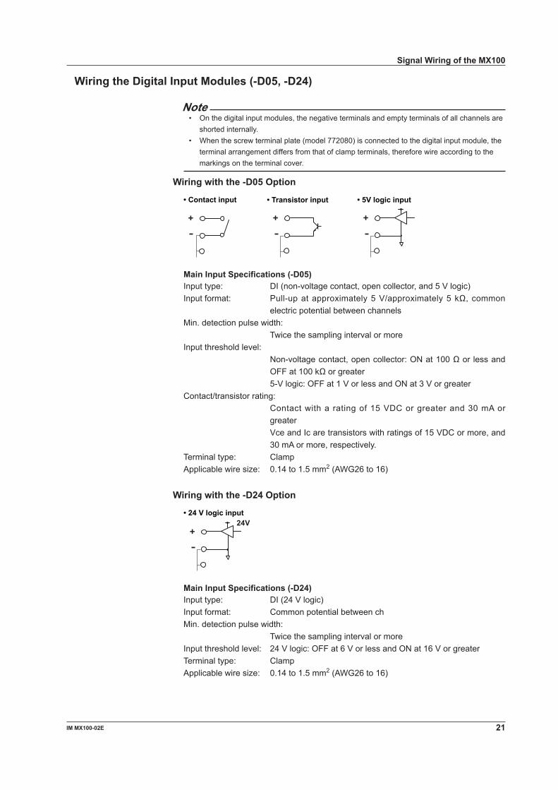
Wiring the Digital Input Modules (-D05, -D4)
Note• On the digital input modules, the negative terminals and empty terminals of all channels are
shorted internally.• When the screw terminal plate (model 772080) is connected to the digital input module, the
terminal arrangement differs from that of clamp terminals, therefore wire according to the markings on the terminal cover.
Wiring with the -D05 Option
• Transistor input• Contact input • 5V logic input
Main Input Specifications (-D05)Input type: DI (non-voltage contact, open collector, and 5 V logic)Input format: Pull-up at approximately 5 V/approximately 5 kΩ, common
electric potential between channelsMin. detection pulse width: Twice the sampling interval or moreInput threshold level: Non-voltage contact, open collector: ON at 100 Ω or less and
OFF at 100 kΩ or greater 5-V logic: OFF at 1 V or less and ON at 3 V or greaterContact/transistor rating: Contact with a rating of 15 VDC or greater and 30 mA or
greater Vce and Ic are transistors with ratings of 15 VDC or more, and
30 mA or more, respectively.Terminal type: ClampApplicable wire size: 0.14 to 1.5 mm2 (AWG26 to 16)
Wiring with the -D4 Option
24V• 24 V logic input
Main Input Specifications (-D4)Input type: DI (24 V logic)Input format: Common potential between chMin. detection pulse width: Twice the sampling interval or moreInput threshold level: 24 V logic: OFF at 6 V or less and ON at 16 V or greaterTerminal type: ClampApplicable wire size: 0.14 to 1.5 mm2 (AWG26 to 16)
Signal Wiring of the MX100

IM MX100-0E
Wiring the Analog Output Modules
External power supply Voltage
V+
Load
+ 24 Vpower supply
(when using current output)
Direction ofcurrent
Vext
Current
I+
Load
CAUTIONTwo power supply terminals are connected internally. Therefore, do not connect a separate external power supply to them as fire can result.
Main Output SpecificationsTerminal type: Clamp, attached and removed in units of 4 channelsLoad impedance: Voltage 5 kΩ or more Current 600 Ω or lessApplicable wire size: 0.08 to 2.5 mm2 (AWG28 to 12)
Wiring the PWM Output Modules
External power supply Pulse width output
V+
Load
+4-28 Vpower supply
CAUTIONTwo power supply terminals are connected internally. Therefore, do not connect a separate external power supply to them as fire can result.
Main Output SpecificationsOutput capacity: 1A/ch max, however, 4 A or less total for all modules*1, *2
Terminal type: Clamp, attached and removed in units of 4 channelsApplicable wire size: 0.08 to 2.5 mm2 (AWG28 to 12)
*1 A 1A current limit circuit is built in to the output circuit. Once the current limit circuit is ON, the circuit continues to operate unless the external power supply is turned OFF.
*2 This module has a built-in fuse. The built-in fuse protects against fires or abnormal emissions of heat due to load shortages or other abnormalities.
Signal Wiring of the MX100

IM MX100-0E
Wiring the Digital Output Module
C
NO250 VDC/0.1 A, 250 VAC/2 A, or30 VDC/2 A (resistance load)
Main Output SpecificationsContact mode: A contact (SPST)Contact capacity: 250 VDC/0.1 A, 250 VAC/2 A, or 30 VDC/2 A (resistance load)Terminal type: Clamp, attached and removed in units of 5 channelsApplicable wire size: 0.08 to 2.5 mm2 (AWG28 to 12)
NoteDo not connect anything to the empty terminals of the digital output module.
Signal Wiring of the MX100

4 IM MX100-0E
Connection to the Network
Connecting the Ethernet Cable to the Main ModuleConnect the Ethernet cable to the Ethernet port (10BASE-T/100BASE-TX) of the main module. Use a UTP cable (category 5 or better) or an STP cable for the Ethernet cable.
RJ-45 modular jack
Ethernet port
Ethernet cable
Checking the Communication StatusYou can check the status on the two LEDs at the upper-right and lower-right of the Ethernet port.
ETHERNET
10BASE - T100BASE - TX
LINK LEDIlluminates in orange when the link betweenthe MX100 and the connected device is established and communication is mutually possible.
ACT LEDBlinks green when transmitting/receiving packets.
Connection to the PCMake the connection via a hub. As shown in the figure below, connect the MX100 to the PC locally using a one-to-one relationship.
MX100
Hub
MX100
Ethernet port
PC
Ethernet cable(straight cable)
System requirements for the MX100 Standard SoftwareOSWindows 2000 Professional SP4, Windows XP SP2 (excluding x64 Edition), Windows Vista Home Premium (excluding the 64-bit Edition), or Windows Vista Business (excluding the 64-bit Edition).
PCFor Windows 2000 and Windows XP:
PC with an Intel Pentium II, 400 MHz or higher CPU (Pentium III, 1 GHz or higher recommended), and at least 256 MB of memory (512 MB or more recommended)
For Windows Vista: PC with an Intel Pentium 4, 3.0 GHz or higher CPU and at least 1 GB of memory (2 GB or more recommended)
Hard diskFree space: 50 MB or more (1 GB or more recommended)RPM: 7200 rpm or more
Display1024 × 768 dot resolution or higher (1280 × 1024 dots or higher recommended), 65536 colors or moreWith Windows Vista, a video card recommended for the OS
Note• The NIC on the PC should support 100BASE-TX (recommended) or 10BASE-T.• When connected to an external network, the communications within the network other than
those related to the MX100 may hinder the measurement operations on the MX100.

5IM MX100-0E
Setup Procedures of the MX100 Standard Software
For details on the setup procedure, see the MX100 Standard Software User’s Manual (IM MX180-01E). For the MX100 Standard Software system requirements, see “Connection to the PC” in “Connection to the Network.”
Installing the MX100 Standard SoftwareInsert the MX100 Standard Software Setup CD-ROM in to the CD-ROM drive. The language selection screen appears. Select the language and the setup program automatically starts. If the installer does not automatically start, double-click SETUP.EXE in the DISK1 folder in the English folder on the CD-ROM.After the setup program starts, follow the instructions that appear on the screen.In the middle of the installation, a dialog box shown below opens prompting you to enter the serial number. The serial number is written on the label that is attached to the front of the case for the MX100 Standard Software Setup CD-ROM.
Installation ResultWhen the software program is installed properly, the folder MX100 Standard is created in the specified directory (C:\ by default). MX100 Standard is registered in the program list and MX100 Standard (referred to as the Integration Monitor in this operation guide), MX100 Viewer, and MX100 Calibration are registered under it.

6 IM MX100-0E
Operations of the MX100 Standard Software
Connecting to or Disconnecting from the MX100Before carrying out the following procedure, check that the power switch on the MX100 is ON and that the PC is connected to the MX100 locally in a one-to-one relationship as shown under “Connection to the PC” in “Connection to the Network.”
When Connecting for the First Time1. Enter the IP address and subnet mask of the PC as shown in the figure below.
Set the IP address of the PC to a fixed address (192.168.1.100, for example), not dynamically. Set the subnet mask to 255.255.255.0. Leave the default gateway blank or set it to 0.0.0.0.
The dialog box in the left figure appears on Windows 2000. To open this dialog box, choose Properties from the MyNetwork Places short-cut menu. Then, choose Local Area Connection > Properties under the General tab > Internet Protocol (TCP/IP) > Properties.On Windows XP, open Control Panel,choose Network and Internet Connections > Network Connections > Local Area Connection Properties > Internet Protocol (TCP/IP) under the General tab > Properties.
2. Click Programs > MX100 Standard > MX100 Standard.The Integration Monitor starts.
3. Click Search.If an MX100 is found, icons appear in the frame containing the Search button for MX100s in the same network segment.
Icon indicating the connected MX100
Clicking here causes the 7-segment LED ofthe connected MX100 to display --CALL--.
Note• If an icon for an MX100 does not appear, see “When Connection Cannot Be Made or When
Connecting to Another MX100.”• If multiple MX100s are connected in the same network segment, all of those MX100s are
detected and their icons are displayed.

IM MX100-0E
4. Click the icon indicating the MX100.The network information about the MX100 appears.
Click the icon Network information
5. Click Edit Network setup and enter the machine name and IP address.When you click Edit Network setup, the Machine Name, IP Address, Subnet Mask, and Default Gateway items turn in to text boxes.You can enter the machine name using up to 64 alphanumeric characters, but the entry is optional.The default value of the IP address, subnet mask, and default gateway is 0.0.0.0. A connection to the network cannot be made if the default IP address and subnet mask values are used. For example, the IP address could be changed to 192.168.1.XX (where XX is 1 to 99 or 101 to 254), and the subnet mask could be changed to 255.255.255.0. The default gateway is set to 0.0.0.0 (default value).
6. Click Apply.
Click Apply.
1
2
3
Click Edit Network setup.
Enter the host name and IP address
No need to change
The network information disappears, and the machine name is displayed in the icon indicating the MX100.
Displays the machine name
Operations of the MX100 Standard Software

IM MX100-0E
7. Click the icon indicating the MX100 again.
The network information about the connected MX100 appears again.
8. Click Connect.
Click the iconNetwork information
Click Connect.
When connected, the Monitor screen opens as shown in the figure below.
Disconnecting1. Click Connection on the Monitor bar.
Monitor bar
Click Connection.
Operations of the MX100 Standard Software

9IM MX100-0E
2. Click Disconnect.
Click Disconnect.
Reconnecting to the Same MX100• If the Connection screen is opened, click Connect.
Click Connect.IP address of the MX100 connected previously
• If the Integration Monitor is closed, start the Integration Monitor. The connection is made automatically when you start the Integration Monitor.
When Connection Cannot Be Made or When Connecting to Another MX100If the MX100 that you are connecting to is already connected by another user or the connection cannot be made such as due to an incorrect designation of the IP address and you try to make a connection, the dialog box shown below remains on the screen.
If this happens, click Cancel in the dialog box, and click Search on the Connection screen. If the MX100 is in the same network segment as the PC, an icon indicating the MX100 appears in the frame containing the Search button. If the icon appears, click the icon to check the network information (see page 27). The user connected to the MX100 is indicated by User; the software program connected to the MX100 is indicated by Software.
Click Search.
NoteIf the module configuration changes before connecting an MX100 that has been connected previously, a message, “Some detected modules do not match the current software configuration. Rebuild based on the current MX hardware setup?” appears. For procedures in this situation, see “Reconfiguring the System” in section 2.2 of the MX100 Standard Software User’s Manual (IM MX180-01E).
Operations of the MX100 Standard Software

0 IM MX100-0E
Setting the Acquisition Conditions of the Measured DataClick Acquisition on the Monitor bar. Set the conditions on the Acquisition setup screen.
Set the monitor interval and record interval
Set the record start/stop conditions Click
Set the save destination and name of the record file
Setting the Monitor Interval and Record IntervalSets the data measurement interval. The data monitor update interval and the alarm detection interval follow this setting. However, if the specified monitor interval is short, the data monitor update interval may be slower depending on the PC environment. If the monitor interval is set greater than or equal to 2 minutes, the Integration Monitor acquires data from the MX100 at the specified interval, but the measurement interval and alarm detection interval on the MX100 are to 1 minute. The input modules can be divided into three interval groups, and different monitor intervals can be specified for each. As shown below, you can assign an input module to any of the three groups by dragging the input module on to a group.The record interval is the interval for saving the measured data to the hard disk or other storage medium. Different record intervals can also be specified for each group. Set the record interval by entering an integer multiple (up to 128) of the monitor interval for the group.
Drag and drop the iconof the input module toa interval group.
Set the record interval as an integer multiple of themonitor interval.Select the monitor interval from the drop-down list box.
Slot number
Move the pointer over an icon to display an overview of the input modules
* For math group settings, see the MX100 Standard Software User’s Manual (IM MX180-01E).
NoteThe shortest interval that you can specify for the monitor interval is the longest measurement interval of the shortest measurement intervals of all the input modules assigned to the same interval group. For example, if an input module with the shortest measurement interval of 10 ms and an input module with 100 ms are assigned, 100 ms is the shortest interval that can be specified for the group.
Operations of the MX100 Standard Software
1IM MX100-0E
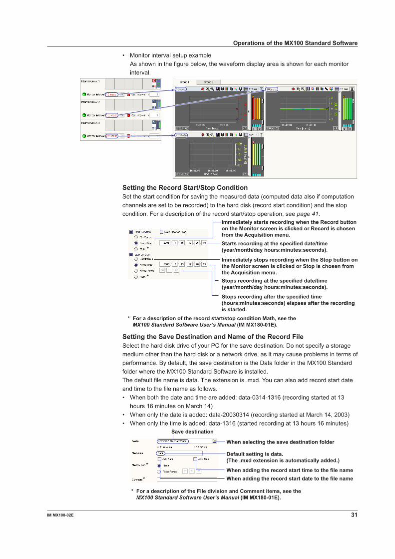
• Monitor interval setup example As shown in the figure below, the waveform display area is shown for each monitor
interval.
Setting the Record Start/Stop ConditionSet the start condition for saving the measured data (computed data also if computation channels are set to be recorded) to the hard disk (record start condition) and the stop condition. For a description of the record start/stop operation, see page 41.
Immediately starts recording when the Record buttonon the Monitor screen is clicked or Record is chosenfrom the Acquisition menu.Starts recording at the specified date/time(year/month/day hours:minutes:seconds).
* For a description of the record start/stop condition Math, see theMX100 Standard Software User’s Manual (IM MX180-01E).
Immediately stops recording when the Stop button onthe Monitor screen is clicked or Stop is chosen fromthe Acquisition menu.Stops recording at the specified date/time(year/month/day hours:minutes:seconds).
Stops recording after the specified time(hours:minutes:seconds) elapses after the recordingis started.
*
*
Setting the Save Destination and Name of the Record FileSelect the hard disk drive of your PC for the save destination. Do not specify a storage medium other than the hard disk or a network drive, as it may cause problems in terms of performance. By default, the save destination is the Data folder in the MX100 Standard folder where the MX100 Standard Software is installed.The default file name is data. The extension is .mxd. You can also add record start date and time to the file name as follows.• When both the date and time are added: data-0314-1316 (recording started at 13
hours 16 minutes on March 14)• When only the date is added: data-20030314 (recording started at March 14, 2003)• When only the time is added: data-1316 (started recording at 13 hours 16 minutes)
Save destination
When selecting the save destination folder
* For a description of the File division and Comment items, see theMX100 Standard Software User’s Manual (IM MX180-01E).
When adding the record start time to the file name
Default setting is data.(The .mxd extension is automatically added.)
When adding the record start date to the file name
*
*
Operations of the MX100 Standard Software

IM MX100-0E
Setting Measurement ConditionsClick Channel on the Monitor bar to display the Channel setup screen. Click the Meas. Channel tab.Set the items other than input mode and measurement range as necessary. For a description of setting alarms on measurement channels, see page 42. For a description of setting DO channels, see page 44. For a description of setting up computation channels, see page 46. For details about other channel settings, see the MX100 Standard Software User’s Manual (IM MX180-01E).
* Cannot be used when Mode is set to RRJC
Channel numberSelect to record, or clear to not record
Select to monitor, or clear to not monitorSelect the input modeSelect the measurement range
Minimum/Maximum value of spanCheck here to perform scaling*Decimal point position of the scale
Select the reference channel for differential input*
Check here to measure the differential input (difference with respect to the measured value of the reference channel)*
Maximum/Minimum values of the scale*
ClickMeasurement channel tab
Icon of the attached moduleClick the icon to select the channels settings of the module.
Select the reference channel for the remote RJC (valid only when the input mode is set to RRJC (TC))
For instructions on these buttons, see the explanation under “Changing the Display Conditions” on page 37.
Unit (up to six characters, only when theUse check box of Scale is selected)
Point to the icon to displayinformation about the module
Enter the tag comment (up to 30 characters)
Enter the tag number (up to 15 characters)
Set the time constant of the first-order lag filter (when the input mode is set to something other than DI)Set the burnout (valid only when the input mode is set to TC)
Set the RJC (valid only when the input mode is set to TC)
Operations of the MX100 Standard Software

IM MX100-0E
Set the initial balance for strain input channels (only when the input mode is set to STR)
Channel NumbersSee “Attachment Position and Channel Numbers of the Input/Output Module” on page 15.
Input Mode and Measurement RangeSelect the input mode and range according to the input signal. The input types and measuring ranges vary depending on the module used.• VOLT (DC voltage) Select the measurement range from 20 mV, 60 mV, 200 mV, 2 V, 6 V, 20 V, or 100 V.• TC (thermocouple) Select the thermocouple type (referred to as Range in the setup) from Type-R,
Type-S, Type-B, Type-K, Type-E, Type-J, Type-T, Type-N, Type-W, Type-L, Type-U, or KpvsAu7Fe.
• RTD1 (resistance temperature detector, measurement current: 1 mA) Select the RTD type (referred to as Range in the setup) from Pt100, JPt100, HQ
Pt100 (high-resolution Pt100), HQ JPt100 (high-resolution JPt100), Ni100: SAMA (Ni100 1mA SAMA), Ni100: DIN (Ni100 DIN), Ni120, Pt50, Cu10:GE, Cu10:L&N, Cu10 :WEED, Cu10:BAILEY, or J263B.
• RTD2 (resistance temperature detector, measurement current: 2 mA) Select the RTD type (referred to as Range in the setup) from Pt100, JPt100, HQ
Pt100 (high-resolution Pt100), HQ JPt100 (high-resolution JPt100), Pt50, Cu10:GE, Cu10:L&N, Cu10:WEED, Cu10:BAILEY, or J263B.
• RTDEX (resistance temperature detector, measured current: 0.25 mA) Select the RTD type (referred to as Range in the setup) from Pt500 (default setting) or
Pt1000.• OHM (resistance) Select a measurement range of 20 ohm (measured current: 1 mA), 200 ohm (measured
current: 1 mA), or 2 kohm (measured current: 0.25 mA).• DI (digital input) Select LEVEL (voltage input) or CONTACT (non-voltage contact input) for the
measurement range to match the input.• STR (strain) Select a measurement range of 2000 µSTR, 20000 µSTR (default value), or 200000
µSTR.• RRJC (TC) only when measuring temperature using TCs Select a channel when referring to the temperature of a relay terminal (the
temperature input of the relay terminal is specified at RRJC Ref. Ch.).
Operations of the MX100 Standard Software
4 IM MX100-0E
Setting the Measurement SpanSet the minimum and maximum values of the range that is actually measured within the measurable range.
Setting the ScaleSet this item when linearly scaling the measured values. Set the scale by entering the maximum and minimum values corresponding to the maximum and minimum values of the measurement span and selecting the decimal point position of the scaled value. You can also assign a unit (up to 6 characters) to the scaled value.
Setting the Reference Channel for Differential InputSet this item when making the difference between the measured value of the channel and the measured value of the reference channel the measured value. Set the reference channel to a measurement channel with the same measurement range and whose Monitor check box is selected.
Setting the Remote RJC Reference Channel (Valid Only When the Input Mode Is Set to RRJC (TC)Set the reference channel for the remote RJC. The thermocouple type of the reference channel must be the same.
Setting the Time Constant of the First-Order Lag Filter (Valid Only When the Input Mode Is Set to Something Other Than DI)A first-order lag filter is available. Set the time constant (time until 63.2% of the output value is reached) for the case when the measurement interval is set to 1 s.
Setting the Burnout (Valid Only When the Input Mode Is Set to TC)Select the burnout detection behavior from the following.• Up: Fix the measured value to +Over (over the upper limit of the measurement
range) when a burnout is detected.• Down: Fix the measured value to -Over (over the lower limit of the measurement
range) when a burnout is detected.• Off: Burnouts are not detected.
Setting the RJC (Valid Only When the Input Mode Is Set to TC)Select whether to use the internal reference junction compensation function of the input module or an external reference junction compensation function. When using the external reference junction compensation function, set an appropriate reference junction compensation voltage in the range of -20000 µV to 20000 µV.
Initial Balancing of Strain Input Channels (Initial Unbalance Value Adjustment)When configuring a bridge circuit with a strain gauge, the bridge circuit will not necessarily be balanced even if the strain of the circuit under test is zero due to the slight deviation in resistance of the strain gauge, and the measured value may not be zero (the value in such cases is called the initial unbalanced value).Therefore, when taking measurements you must first balance the bridge and, if the strain is zero, obtain a measured value of zero. This is called initial balancing. (setting the initial unbalanced value to zero).
Operations of the MX100 Standard Software

5IM MX100-0E
Monitoring the Measured Data and Setting the DisplayClick Monitor on the Monitor bar. You can monitor the measured data on the Monitor screen that opens.
Monitoring the Data Using Trend Waveforms
Switch to waveform, numeric, or waveform and numeric display
Y-axis
Channel number and measurement unit
Turn ON/OFF the waveform
Change the background darkness
Switch the Y-axisChange the grid density
Turn ON/OFF the waveformdisplay limit (clip)
Switch the waveform widthSwitch the display zoneZoom in or out of the time axisSwitch the display group
Add a mark (cannot be used when paused)
Click
Monitoring the Data Using Numeric Values
Unit
Level indication with respect to the scale width
When the measured value exceeds the measurement range
When a measured or computed value is invalid
Switch to waveform, numeric, or waveform and numeric display
Numeric displayAlarm indication
Channel display colorChannel number
Operations of the MX100 Standard Software

6 IM MX100-0E
Monitoring the Data Using Trend Waveforms and Numeric Values
Numeric display screen Waveform display screen
Switch the display group
Change the display areaWhen paused, you can drag to change the display area of the digital and waveform displays.
Switch to waveform, numeric, or waveform and numeric display
Updating the Display Using the Display Menu and the Information Displayed on the Status Bar
Turn ON/OFF the displayedinformation on the status bar
Turn ON/OFF the status barTurn ON/OFF the toolbar
Switch between channel number,tag number, and tag comment
Communication statusDisk space Current timeFile creation
Communication status : Connected
Monitor/Record status : Monitoring : Recording
Write statusNumber of data files created
Displays the remaining time untilthe next file is created using a bar
Displays the remainingdisk space using a bar
Displays the data rateusing a bar
: Data dropout occurred
: Writing : Write error
: Disconnected
Operations of the MX100 Standard Software

IM MX100-0E
Changing the Display ConditionsClick Display on the Monitor bar. You can change the display conditions on the Display setup screen that opens. The automatic channel assignment function is convenient for assigning all the channels that were specified to be monitored in “Setting the Measurement Conditions” on page 32 to the display groups.
Channel display colorTrip point
Display zone positionMaximum/Minimum value of the scale
Select the display format of the Y-axis (normal/exponent)
Select the Y-axis type (linear/logarithmic)
Turn scale ON/OFF when displaying multi-axes zone
Channel select buttonDisplay ON/OFF
Switch the display groupGroup name
Execute automatic channel assignmentNumber of channels assigned automatically
Restore the default maximum and minimum values of the entire scale
Turn ON/OFF the trip point display
Click
To not copyTo copy
Reset to defaultWhen making the settings the sameas the first item
Assign channels automaticallyTurn ON/OFF collectively
Display Groups and Group NamesThe Monitor screen displays waveforms or numeric values by dividing the channels into groups. The measured/computed values can be divided into up to 10 groups. Up to 32 channels can be registered to a single group. The channels that can be registered are those whose Monitor check boxes are selected on the Channel setup screen. When you click a channel selection button on the Display setup screen, the channel numbers of the channels that can be registered are displayed (see the figure below). You can also select the channel by tag number or tag comment by switching the tab.You can enter a group name using up to 30 characters. By default, group names Group 1 to Group 10 are assigned.
Operations of the MX100 Standard Software
IM MX100-0E
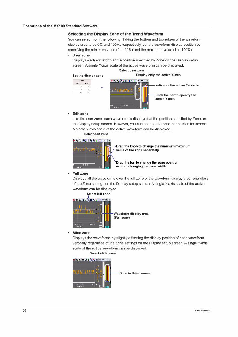
Selecting the Display Zone of the Trend WaveformYou can select from the following. Taking the bottom and top edges of the waveform display area to be 0% and 100%, respectively, set the waveform display position by specifying the minimum value (0 to 99%) and the maximum value (1 to 100%).• User zone Displays each waveform at the position specified by Zone on the Display setup
screen. A single Y-axis scale of the active waveform can be displayed.
Select user zone
Click the bar to specify theactive Y-axis.
Display only the active Y-axis
Indicates the active Y-axis bar
Set the display zone
• Edit zone Like the user zone, each waveform is displayed at the position specified by Zone on
the Display setup screen. However, you can change the zone on the Monitor screen. A single Y-axis scale of the active waveform can be displayed.
Select edit zone
Drag the knob to change the minimum/maximumvalue of the zone separately
Drag the bar to change the zone positionwithout changing the zone width
• Full zone Displays all the waveforms over the full zone of the waveform display area regardless
of the Zone settings on the Display setup screen. A single Y-axis scale of the active waveform can be displayed.
Select full zone
Waveform display area(Full zone)
• Slide zone Displays the waveforms by slightly offsetting the display position of each waveform
vertically regardless of the Zone settings on the Display setup screen. A single Y-axis scale of the active waveform can be displayed.
Select slide zone
Slide in this manner
Operations of the MX100 Standard Software

9IM MX100-0E
• Auto zone Displays the trend waveforms by dividing the waveform display area evenly according
to the number of displayed waveforms regardless of the Zone settings on the Display setup screen.
Select auto zone
Divide evenly automatically
• Multi-axes zone All the Y-axis scales of the displayed waveforms are aligned horizontally. To hide a
Y-axis scale, clear the Y-Axis check box on the Display setup screen. The display zone is set to the position specified by Zone on the Display setup screen.
Turn OFF the Y-axisdisplay of Ch00002
The Y-axis of Ch00002is not displayed.
Select multi-axes zone
Click the bar tomove the activeY-axis to the left end
Indicates the activeY-axis bar
Trip PointYou can display a trip line to indicate a particular value of interest (trip point) in the waveform display area. Two trip points (trip 1 is red, trip 2 is blue) can be set on each waveform. The trip line of the waveform corresponding to the left-most Y-axis is shown in the waveform display area.
Turn ON the trip line display
Trip 1 value
Trip 2 value Trip lineTrip 1 value
Trip 2 value
Y-axis bar at theleft end
Clipping of Trend WaveformsBy default (clip OFF), the waveform is not displayed when the measured/computed value exceeds the minimum/maximum value of the scale (see the lower left figure). When clip is turned ON, values that are smaller than the minimum value of the scale are displayed as the minimum value and the values that are larger than the maximum value of the scale are displayed as the maximum value.
Clip OFF Clip ON
Operations of the MX100 Standard Software

40 IM MX100-0E
Displaying MarksYou can display marks in the trend waveform area (see the figure below). You can enter a text to be attached to the mark (“Mark” by default) using up to 15 characters. Click the Mark button or choose Mark Configuration from the Action menu. You can enter the text in the dialog box that opens.
MarkMark setup dialog box
Text of the specified mark
Enter the text to bedisplayed as a mark
Check here to display marks without displaying this dialog box
Pausing the Updating of the Monitor Display and Reading Measured Values Using Cursors
Pausing and Resuming the Updating of the Monitor DisplayClick the Pause button on the Monitor screen or choose Pause from the Acquisition menu to stop the updating of the monitor display. When paused, the word “Pause” under the button toggles between red and black. To resume the updating, click the Pause button on the Monitor screen or choose Pause release from the Acquisition menu.
Click
or
Choose
NoteRecording continues even when the updating of the monitor display is stopped.
Reading Measured Values Using CursorsYou can read measured values (computed values) using cursors when the updating of the monitor display is paused. Click the position where you wish to read the value in the waveform display area. If you wish to read another point simultaneously, drag the cursor. Cursor A appears at the position where you first clicked; Cursor B appears at the position where you released the mouse button. The measurement point is indicated by a yellow circle at the cross point of the cursor and waveform.
Change the display area
Time at Cursor BTime at Cursor A
Scroll barScroll buttonMeasurement pointCursor BCursor ACursor movement button
Time between Cursors A and B
(value B) − (value A)Readout value of Cursor BReadout value of Cursor AChannel numberWaveform display color
Operations of the MX100 Standard Software

41IM MX100-0E
To clear the cursors, choose Hide Cursor from the View menu.
Choose
Recording the Measured DataFor details on setting of the record start condition and setting the save destination and file name of the record file, see page 30.Record Start OperationClick the Record button on the Monitor screen, or choose Record from the Acquisition menu.
Click
or
Choose
When recording starts, the display changes as shown in the figure below. To divide the file during recording, click the Manual Save button or choose Manual Save from the Acquisition menu.
When dividing files
Changes to red when recording starts
Changes to red when recording starts
Elapsed time of recording
or
Choose
If Start Condition described is not set to On Record, recording does not start until the specified condition is met. While the Start Condition is not met, the word “Waiting” appears under the Record button (see figure below).
Record Stop OperationTo stop recording when Stop Condition described is set to Manual or before the Stop Condition is met, click the Stop button or choose Stop from the Acquisition menu. When the message “Stop Record?” appears, click OK.
Click
or
Choose
Operations of the MX100 Standard Software
4 IM MX100-0E
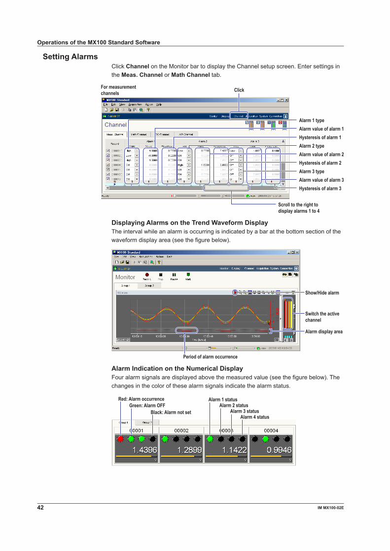
Setting AlarmsClick Channel on the Monitor bar to display the Channel setup screen. Enter settings in the Meas. Channel or Math Channel tab.
Scroll to the right to display alarms 1 to 4
Hysteresis of alarm 3Alarm value of alarm 3Alarm 3 typeHysteresis of alarm 2Alarm value of alarm 2Alarm 2 typeHysteresis of alarm 1Alarm value of alarm 1Alarm 1 type
For measurementchannels Click
Displaying Alarms on the Trend Waveform DisplayThe interval while an alarm is occurring is indicated by a bar at the bottom section of the waveform display area (see the figure below).
Alarm display area
Show/Hide alarm
Switch the active channel
Period of alarm occurrence
Alarm Indication on the Numerical DisplayFour alarm signals are displayed above the measured value (see the figure below). The changes in the color of these alarm signals indicate the alarm status.
Alarm 1 statusAlarm 2 status
Alarm 3 statusAlarm 4 status
Black: Alarm not setGreen: Alarm OFF
Red: Alarm occurrence
Operations of the MX100 Standard Software
4IM MX100-0E
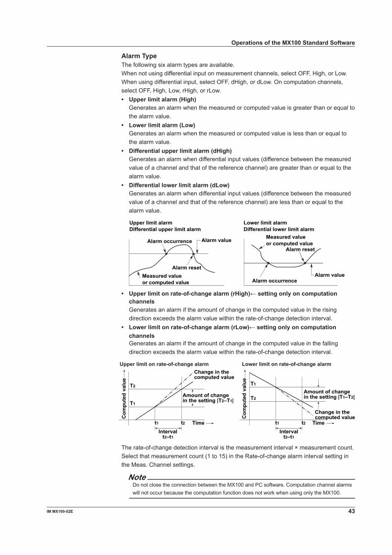
Alarm TypeThe following six alarm types are available.When not using differential input on measurement channels, select OFF, High, or Low. When using differential input, select OFF, dHigh, or dLow. On computation channels, select OFF, High, Low, rHigh, or rLow.• Upper limit alarm (High) Generates an alarm when the measured or computed value is greater than or equal to
the alarm value.• Lower limit alarm (Low) Generates an alarm when the measured or computed value is less than or equal to
the alarm value.• Differential upper limit alarm (dHigh) Generates an alarm when differential input values (difference between the measured
value of a channel and that of the reference channel) are greater than or equal to the alarm value.
• Differential lower limit alarm (dLow) Generates an alarm when differential input values (difference between the measured
value of a channel and that of the reference channel) are less than or equal to the alarm value.
Alarm value
Alarm reset
Alarm occurrence
Upper limit alarmDifferential upper limit alarm
Lower limit alarmDifferential lower limit alarm
Measured valueor computed value
Alarm reset
Alarm valueAlarm occurrence
Measured valueor computed value
• Upperlimitonrate-of-changealarm(rHigh)←settingonlyoncomputationchannels
Generates an alarm if the amount of change in the computed value in the rising direction exceeds the alarm value within the rate-of-change detection interval.
• Lowerlimitonrate-of-changealarm(rLow)←settingonlyoncomputationchannels
Generates an alarm if the amount of change in the computed value in the falling direction exceeds the alarm value within the rate-of-change detection interval.
Com
pute
d va
lue
Change in thecomputed value
T1
Time
T2
t1 t2
Amount of changein the setting |T2–T1| T2
Time
T1
t1 t2
Change in thecomputed value
Intervalt2–t1
Intervalt2–t1
Upper limit on rate-of-change alarm Lower limit on rate-of-change alarm
Com
pute
d va
lue
Amount of changein the setting |T1–T2|
The rate-of-change detection interval is the measurement interval × measurement count. Select that measurement count (1 to 15) in the Rate-of-change alarm interval setting in the Meas. Channel settings.
NoteDo not close the connection between the MX100 and PC software. Computation channel alarms will not occur because the computation function does not work when using only the MX100.
Operations of the MX100 Standard Software

44 IM MX100-0E
Alarm HysteresisYou can set a width (hysteresis) to the values used to activate and release alarms. Alarm hysteresis prevents frequent activation and release of alarms when the measured/computed value is unstable around the alarm value.
Alarmsetting
Alarm releaseMeasured value
Alarm activated
Upper limit alarm Lower limit alarm
Measured valueAlarm release
Hysteresis
Alarm settingAlarm activated
Digital OutputClick Channel on the Monitor bar to display the Channel setup screen. Set the output of the digital output module in the DO Channel tab.
Output channel numberFirst alarm reference channel number
Last alarm reference channel numberSelect output or not output
Select the output action Turn ON/OFF alarms 1 to 4
Select manual DO buttons
Select energize/de-energize of output relay
Select hold/non-hold of output relay
ClickDO Channel tab
Selecting the Action for the Digital OutputThe digital output can be enabled for the following causes.• Alarm output Outputs a signal when an alarm occurs according to the alarm settings.• Manual DO When the manual DO button on the Monitor screen is clicked, all the DO channels
assigned to the button number output relay contact signals collectively.
Manual DO buttonClick to switch ON/OFF
• FAIL output Outputs a relay contact signal when a error occurs in the main module CPU.• Error output Outputs a relay contact signal when any of the following events occur.
• A data output request timeout (60 s) occurs while recording data.• A module error occurs.
Operations of the MX100 Standard Software

45IM MX100-0E
Energized/De-energized Operation of Output RelaysYou can select whether the output relay is energized or de-energized when an output event (such as an alarm) occurs. If de-energized is selected, the output relay behaves in the same fashion as when an output event occurs if the power is shut down. The default setting is Energized. The FAIL output is fixed to De-energized.
NOEnergize
De-energize
C NO C NO C
NO C NO CNO C
When power isshut down
NO: Normally Opened, C: Common
When alarm isnot occurring
When alarm isoccurring
Hold/Non-Hold of Output RelaysSelect the behavior of the output relay when an output event is released (recovers to a normal condition). The default setting is Non-hold• Turn OFF the output relay with the release of the output event (non-hold).• Hold the output relay at ON until the Relay ACK button (see below) is clicked.
Relay ACK button
Output causeoccurrence
• When set to non-hold • When set to hold
Relay output ON
Relay output OFF
Relay ACK
Relay output ON
Relay output OFF
Output causeoccurrence
NoteIf connection with the PC is dropped, the state at the point at which the DO output was dropped is retained. However, DO output to which measurement channel alarm detection is assigned functions normally even if the connection with the PC is dropped.
Operations of the MX100 Standard Software

46 IM MX100-0E
Setting the ComputationYou can enter computing equations using operators, constants, and functions. The computed results be displayed and recorded (saved). Computation allows you to determine the average/maximum/minimum of a specified channel on a specified date/time or output events (start/stop record, reset time, etc.) under specified conditions. For details on computations including available operators, constants, and functions, see the MX100 Standard Software User’s Manual (IM MX180-01E).Set computations using Math Channel on the Channel setup screen in the figure below. Set the monitor interval and record interval for computed data on the Acquisition setup screen.
Enter theconstant value
Enter the label foridentifying the constant
Check here to calculate +Over and –Over as maximum and minimum values of the measurement range
Enabled when rHigh or rLow is selected for the type
Settings when using the timer in the computation
Enter the tag comment (up to 30 characters)Enter the tag number (up to 15 characters)
Enter the unit for computed values (up to 6 characters)
Enter the equationSelect to monitor, or clear to not monitorComputation channel numbers
Select to record, or clear to not record (saving of computed data)
ClickMath channel tab
Saving/Loading and Printing of Setup Data (Project)Saving Setup Data (Project)From the File menu, choose Save or Save As to save the setup data. The default save destination is the folder depends on the system that is running. The extension is .mxp. The default file name is NewProject.mxp.
or
Operations of the MX100 Standard Software

4IM MX100-0E
Loading Setup Data (Project)From the File menu, choose Open.
Printing Setup DataFrom the File menu, choose Print. Settings such as the network information of the MX100, information about the attached modules, acquisition conditions, and measurement conditions are printed in tables.
Print image
Operations of the MX100 Standard Software

4 IM MX100-0E
Displaying Recorded Measured Data, Reading Values Using Cursors, and Statistical Computation over an Area
You can display measured or computed data that has been recorded.
1. Choose Programs > MX100 Standard > MX100 Viewer to start the Viewer. You can also choose Launch Historical Viewer from the File menu or click the button on the Integration Monitor.
2. From the File menu, choose Open.
You can also click the button on the toolbar. The Open dialog box opens.
File information
Select the folder specifiedas the save destinationof record files describedon page 30
3. Select the file you wish to load and click Open.
The waveform display window opens.
When a file recorded using the Integration Monitor is opened, a dialog box for confirming whether to carry out synchronization (see the note below) opens. Click Yes or No.
Waveform display window
NoteThe data recorded using the Integration Monitor has time stamps attached by the MX100 (see section 1.2, “Main Module Functions” in the MX100 Data Acquisition Unit User’s Manual (IM MX100-01E)). When synchronization is carried out, the time is corrected to the time on the PC, and the data is saved using the corrected time. The name of the created file remains the same but with a different extension .mxs. The file with .mxd extension before synchronization is not deleted.
Operations of the MX100 Standard Software

49IM MX100-0E
Changing the Display on the Waveform Display WindowYou can change the display using operations similar to the waveform display area of the Monitor screen of the Integration Monitor.
Switch the display group
ScaleTurn ON/OFF the channel
Change the grid density
Channel number and measurement unit
Change the backgrounddarkness
Zoom in or outof the time axis
Switch the display zone
Switch the active waveformAlarm display ON/OFF
Clip display ON/OFF
Zone display area ON/OFF
Move the cursor to the point where the alarm changed
Switch the grid display
Changing the Display Using the ToolbarSee the explanation in the figure below.
Channel number display
Show the General Display Settings window
Tag number displayTag comment display
Switching between Absolute and Relative timeShow the waveform display window
Alarm/Mark ListShow the numeric display window
Show the window for displaying cursor values
Adding marksMove cursor A to the left mark
Move cursor A to the right markMove cursor B to the left mark
Move cursor B to the right mark
Show the window for displaying statistical computation over an area
Changing the Display Using the MenuChoose appropriate commands from the Edit, View, and Window menus to change the display.
Show the computation result display windowShow the window for displaying cursor values
Show the computation result display window
Add/delete a mark
Clear the Cursor Switch between channel number, tag number, and tag commentSwitch between absolute and relative time*Turn ON/OFF the toolbarTurn ON/OFF the status bar
Arrange the display window(select cascade or tile)Arrange window iconsShow the waveform display windowShow the numeric display window
Switch the display window
* Displays also the Format item during numeric display
Select how to arrange the display area from auto, horizontal, and vertical
Change the data file display
Alarm/Mark detailed list display
Operations of the MX100 Standard Software
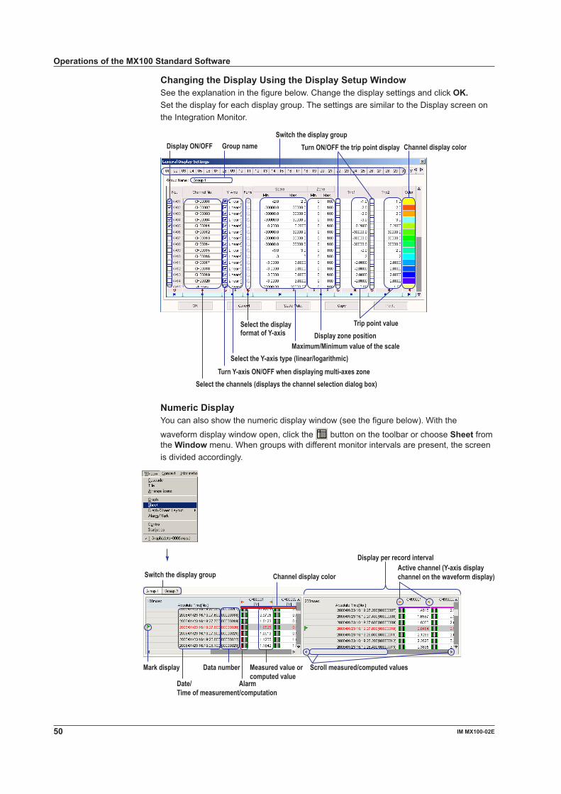
50 IM MX100-0E
Operations of the MX100 Standard Software
Changing the Display Using the Display Setup WindowSee the explanation in the figure below. Change the display settings and click OK.Set the display for each display group. The settings are similar to the Display screen on the Integration Monitor.
Select the displayformat of Y-axis
Switch the display group
Select the channels (displays the channel selection dialog box)
Group nameDisplay ON/OFF
Select the Y-axis type (linear/logarithmic)
Turn Y-axis ON/OFF when displaying multi-axes zone
Maximum/Minimum value of the scale
Turn ON/OFF the trip point display
Trip point value
Channel display color
Display zone position
Numeric DisplayYou can also show the numeric display window (see the figure below). With the
waveform display window open, click the button on the toolbar or choose Sheet from the Window menu. When groups with different monitor intervals are present, the screen is divided accordingly.
Date/Time of measurement/computation
Switch the display group
Alarm
Channel display color
Measured value orcomputed value
Data number
Active channel (Y-axis display channel on the waveform display)
Mark display Scroll measured/computed values
Display per record interval

51IM MX100-0E
Reading Values Using CursorsClick the tab of the group on which you wish to read values using cursors on the waveform display window. Click the position where the measured (computed) data is to be read in the waveform display area on the waveform display window. If you wish to read another point simultaneously, drag the cursor. Cursor A appears at the position where you first clicked; Cursor B appears at the position where you released the mouse button. The measurement point is indicated by a yellow circle at the cross point of the waveform and cursor. You can move the waveform that is displayed in the waveform display area using the scroll buttons or scroll bar.
Cursor ACursor B Measurement point
Group selection tab
You can show a window displaying the cursor measurement values (see the figure below). From the Window menu, choose Control.
Channel number andmeasurement unit
Channel display color
Time between Cursors A and B
Time at Cursor B
Time at Cursor A
(value B) – (value A)Value of Cursor B
Value of Cursor A
Alarmindication
Data number at Cursor A
MoveCursor A
Data number at Cursor BMoveCursor B Difference in the data number between Cursors A and B
Statistical Computation over an Area of Measured DataShow the cursors in the same fashion as when reading the values using cursors. Cursor A is the start position of computation area; Cursor B is the end position of the computation area.From the Window menu, choose Statistics to open the Statistics window shown in the figure below.
Channel number andmeasurement unit Copy data to the clipboard
Channel display color
Data number at the start position of thestatistical computation over an area
Data number at the end position of thestatistical computation over an area
Minimum value
Maximum value
Maximum value – minimum value
Average value
RMS value
Operations of the MX100 Standard Software

5 IM MX100-0E
Alarm/Mark List Display Displays a detailed list of alarms and marks.From the Window menu, choose Alarm/Mark List.You can also click the button on the toolbar.
• Alarm List
Currently sorted to the item indicated by this markSorted according to the clicked item
• Mark List
Mark added by Viewer software
Mark added using an Event function markMark added in the Integration software’s Monitor screen
Names of groups with marksIf the groups have no names, all groups are marked
Currently sorted to the item indicated by this markSorted according to the clicked item
Operations of the MX100 Standard Software

5IM MX100-0E
Printing the Displayed DataTo print waveforms, open the waveform display window; to print numeric values, open the numeric display window. If multiple windows are open, click the window that you wish to print. To print values read by the cursors or statistical computation over an area, open those windows also.After selecting the object to be printed, choose Print Setting from the File menu. In the Print Setting dialog box, set Range, Color, and Print Groups, and then click OK. Then, choose Print from the File menu to execute the printing. When printing numeric values, you only need to set the range.
Enter the comment to be printed
Switch to settings for numeric values
Select the groups when SelectedGroups is selectedClick to open the group selection dialog box
Select monochrome or color print
Select the group to be printed
Select to print all or print only the range specified by cursors
Converting the Format of the Recorded Measured DataConversion can be made into the following formats.ASCII Text data with each data point separated by a comma. The extension is .txt.Excel Data that can be opened using Microsoft’s spreadsheet application Excel version 8.0
(Excel 97) or later. The extension is .xls.Lotus Data that can be opened using IBM’s Lotus 1-2-3 spreadsheet application version 2.0
or later. The extension is .wj2.
From the Convert menu, choose To ASCII, To Excel, or To Lotus. Then, convert the data using the dialog box that opens (see the figure below). There is a limitation in the number of data points that can be handled in the Excel conversion or Lotus conversion. Before executing the conversion, set the channels/groups to be converted, the conversion range, and the step so that the number of data points is appropriate.
Enter the range of group numbers to be converted
Select whether to set the range tobe converted using groups orchannels
Select the range of channels to beconvertedClick to open the selection dialog box.Select the measurement interval
Only the channels with the selectedmeasurement interval are converted
Enter the data range to be convertedCan be specified using cursors beforeopening this dialog box
Displays the time of the specified data
When changing the save destination or file nameClick to open the save destination and file name setup dialog box.
Step when saving data at certainintervals
Displays the save destination andfile name
Operations of the MX100 Standard Software
Recommended