MPCIe-750 Graphics Card for Intel
Galileo
User Manual
Document Reference: User Guide for MPCIe-750-G
Document Issue: 1.00
Contents Introduction ............................................................................................................................................ 3
Regulatory Statements ................................................................................................................... 3
Product Support .............................................................................................................................. 3
Warrantee ....................................................................................................................................... 3
Limitations of Liability ..................................................................................................................... 3
Product Overview ............................................................................................................................... 4
Product Specifications......................................................................................................................... 4
GPU ................................................................................................................................................. 4
Video Memory ................................................................................................................................ 4
VGA Header - P3 .............................................................................................................................. 4
LCD Header - P2 .............................................................................................................................. 5
Touch Screen Controller ................................................................................................................. 5
Product Installation ................................................................................................................................. 6
Installing the MPCIe-750 –16MB-G-LT and LCD430-G-R board onto an Intel Galileo .................... 6
Installing the MPCIe-750 –16MB-G-V board onto an Intel Galileo ............................................... 11
Demo software ..................................................................................................................................... 12
SD Card creation Method 1 ........................................................................................................... 12
SD Card creation Method 2 ........................................................................................................... 12
GRUB configuration for MPCIe-750 .............................................................................................. 13
Arduino development environment ............................................................................................. 13
Arduino demo applications ........................................................................................................... 14
QT demo applications ................................................................................................................... 14
Touch Screen Calibration .............................................................................................................. 14
Introduction This document provides all the information required to setup and get started with the MPCIe-750-
16MB-G-XX graphics card. This variant of the graphics card is designed exclusively for use with the
Intel Galileo Arduino Development board. Other variants of the card are available that are
compatible with embedded boards featuring a spare mini PCI express slot. For information on other
variants of the MPCIe-750 graphics card please contact [email protected]
Regulatory Statements
This product is sold as an evaluation board/kit for use in conjunction with the Intel Galileo
development board and is intended for use for ENGINEERING DEVELOPMENT, DEMONSTRATION, OR
EVALUATION PURPOSES ONLY and is not considered by Micro Passion to be a finished end-product
fit for general consumer use. Persons handling the product(s) must have electronics training and
observe good engineering practice standards. As such, the goods being provided are not intended to
be complete in terms of required design-, marketing-, and/or manufacturing-related protective
considerations, including product safety and environmental measures typically found in end
products that incorporate such semiconductor components or circuit boards. This evaluation
board/kit does not fall within the scope of the European Union directives regarding electromagnetic
compatibility, restricted substances (RoHS), recycling (WEEE), FCC, CE or UL, and therefore may not
meet the technical requirements of these directives or other related directives.
The user assumes all responsibility and liability for proper and safe handling of the goods. Further,
the user indemnifies Micro Passion from all claims arising from the handling or use of the goods. Due
to the open construction of the product, it is the user’s responsibility to take any and all appropriate
precautions with regard to electrostatic discharge.
Product Support
The MPCIe-750-16MB-G-XX is sold on a no support basis, however Micro Passion will at their
discretion offer free technical support over email. Dedicated support contacts can be purchased by
contacting [email protected].
Warrantee
The MPCIe-750-16MB-G-XX is warranted against defects in materials and workmanship for a period
of 90 days from purchase. This warranty does not cover any problems occurring as a result of
improper use, modifications, exposure to water, excessive voltages, abuse, or accidents. All boards
will be returned via standard mail if an issue is found. If no issue is found or express return is
needed, the customer will pay all shipping costs.
Limitations of Liability
In no event shall Micro Passion be held liable for any loss, expenses or damages of any kind
whatsoever, whether direct, indirect, incidental or consequential, arising from the design or use of
this product or the support materials supplied with this product. If this product proves to be
defective, Micro Passion is only obliged to replace or refund the purchase price at Micro Passion's
discretion.
Product Overview The MPCIe-750-16MB-G-XX graphics card has been designed to allow developers utilising the Intel
Galileo board, to add video output capability to projects. Supported displays include VGA / TV
monitors up to 1920x1800 resolution, and raw 18bit TFT LCD Panels also up to 1920x1080
resolution. An on board touch screen controller is provided to allow interactive touch screen LCD
designs to be created.
Product Specifications.
GPU: Silicon Motion SM750
Bus: PCI Express x1
Memory: 16MB MB DDR SDRAM
CRT output: Support display resolution up to 1920 x 1080 and vertical refresh rate
up to 75Hz
LCD output: 18 bit TFT LCD interface
Support display resolutions up to 1920 x 1080
PWM Controlled LED backlight
4 wire resistive touch screen controller
Dual Display Mode: LCD+VGA, supports single, clone and dual mode
Intel Galileo Support: Custom Arduino environment including graphics library compatible
with Adafruit GFX
Custom POKY YOCTO Linux OS including Qt graphics environment
Dimensions: 30mm x 50.95mm
Power Consumption: TBD
GPU
The MPCIe-750-16MB-G-XX graphics card features a Silicon Motion SM750 graphics controller with
integrated 2D accelerator.
Video Memory
The MPCIe-750-16MB-G-XX graphics card implements 16MB onboard video memory.
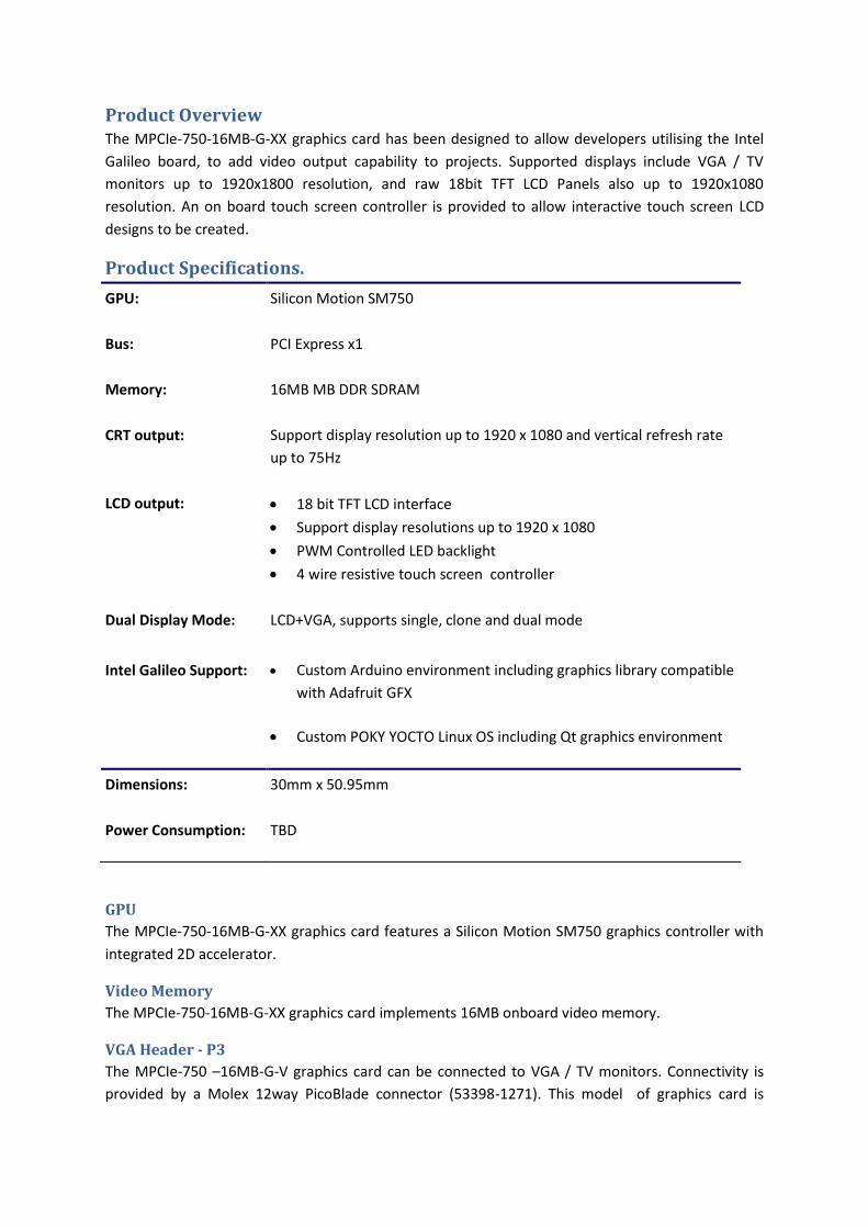
VGA Header - P3
The MPCIe-750 –16MB-G-V graphics card can be connected to VGA / TV monitors. Connectivity is
provided by a Molex 12way PicoBlade connector (53398-1271). This model of graphics card is
packaged with a VGA extension cable of approximately 150mm in length. The pin out of P3 is
detailed below.
Pin Number Description Notes
1 VGA Red
2 5V Out
3 VGA Green
4 Ground
5 VGA Blue
6 No Connect Reserved for EDID data
7 Ground
8 VGA HSYNC
9 Ground
10 VGA VSYNC
11 Ground
12 No Connect Reserved for EDID clock
LCD Header - P2
The MPCIe-750 –16MB-G-LT graphics card can be connected to 18-bit LCD TFT displays, including
displays with integrated 4-wire touch screens. Connectivity is provided by a FCI 40 Way FFC
connector (62684-401100ALF). The Micro Passion LCD430-G-R LCD board is a 4.3" LCD module that
complements the MPCIe-750 –16MB-G-LT graphics card. The pin out of P2 is detailed below.
Pin Number Description Pin Number Description
1 Touch Y+ 21 Green 4
2 Touch X- 22 Green 5
3 Touch Y- 23 Ground
4 Touch X+ 24 Red 0
5 Gound 25 Red 1
6 I2C Clock (Cap Touch) 26 Red 2
7 I2C Data (Cap Touch) 27 Red 3
8 I2C Interrupt (Cap Touch) 28 Red 4
9 Ground 29 Red 5
10 Blue 0 30 Ground
11 Blue 1 31 Display Enable
12 Blue 2 32 Vertical Sync
13 Blue 3 33 Horizontal Sync
14 Blue 4 34 Pixel Clock
15 Blue 5 35 Panel Enable
16 Ground 36 3V3 Power
17 Green 0 37 3V3 Power
18 Green 1 38 Ground
19 Green 2 39 LED Backlight Anode
21 Green 3 40 LED Backlight Cathode
Touch Screen Controller
The MPCIe-750 –16MB-G-LT graphics card features a Microchip AR1100 4 wire resistive touch screen
controller.
Product Installation
Installing the MPCIe-750 –16MB-G-LT and LCD430-G-R board onto an Intel Galileo
Follow ESD precautions when installing the MPCIe-750 –16MB-G-LT and LCD430-G-R board onto an
Intel Galileo.
The following items are required to install the MPCIe-750 –16MB-G-LT and LCD430-G-R boards onto
an Intel Galileo board.
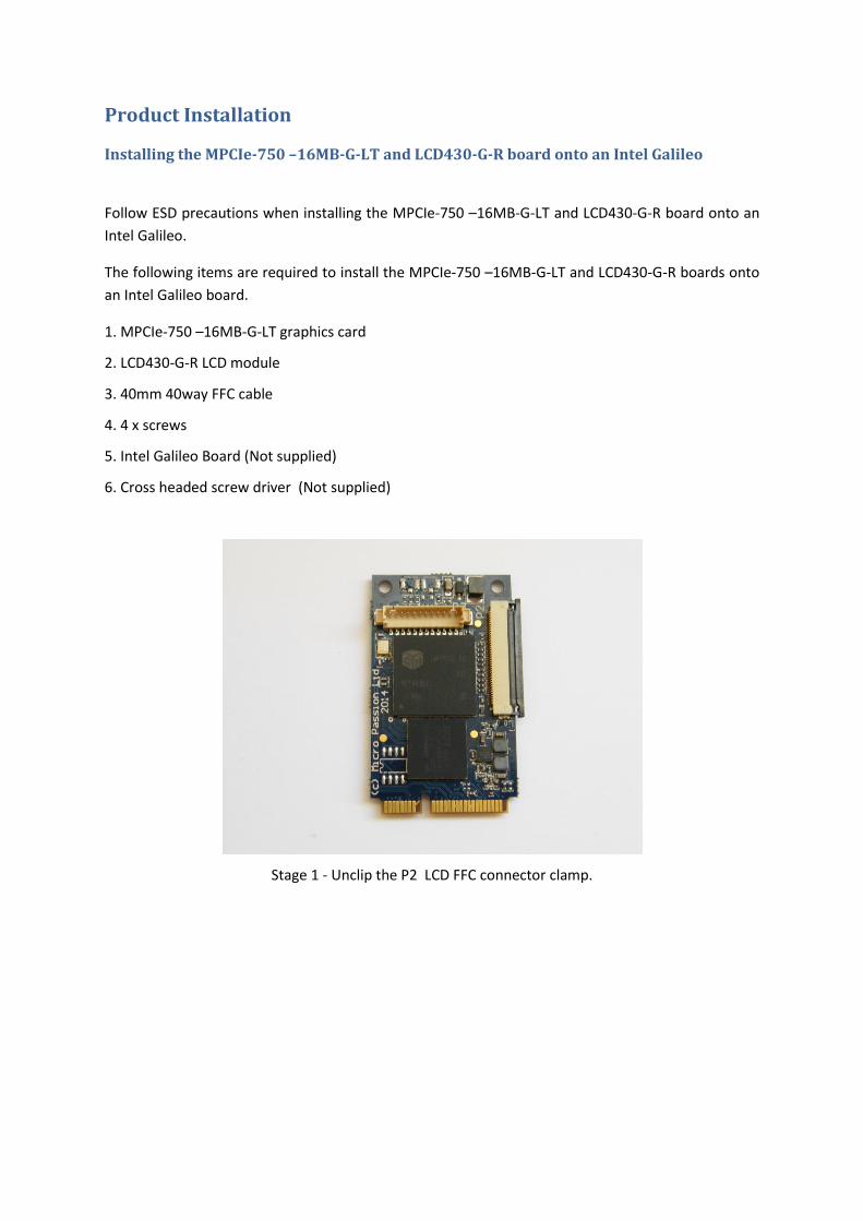
1. MPCIe-750 –16MB-G-LT graphics card
2. LCD430-G-R LCD module
3. 40mm 40way FFC cable
4. 4 x screws
5. Intel Galileo Board (Not supplied)
6. Cross headed screw driver (Not supplied)
Stage 1 - Unclip the P2 LCD FFC connector clamp.

Stage 2 - Insert the 40mm 40way FFC cable into P2 and clamp the cable in place
Stage 3 - Place the Intel Galileo board on a flat surface with the mini PCI express
connector facing up, and Plug in the MPCIe-750 –16MB-G-LT graphics card
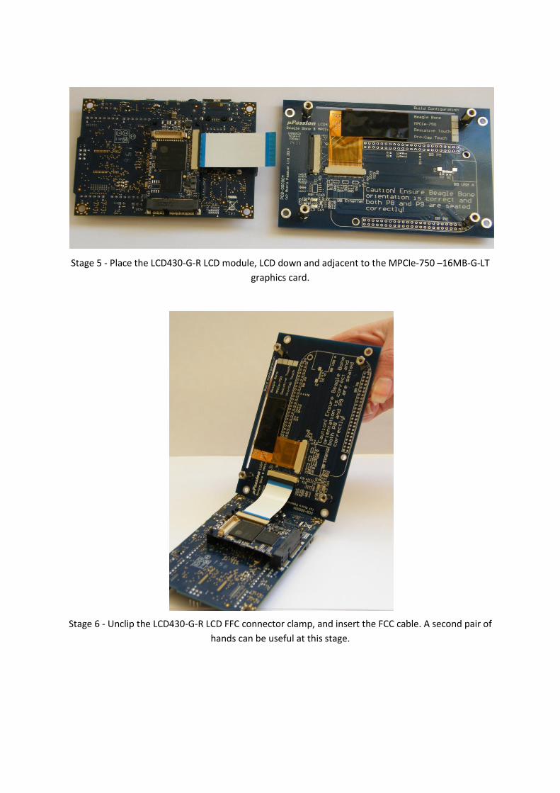
Stage 5 - Place the LCD430-G-R LCD module, LCD down and adjacent to the MPCIe-750 –16MB-G-LT
graphics card.
Stage 6 - Unclip the LCD430-G-R LCD FFC connector clamp, and insert the FCC cable. A second pair of
hands can be useful at this stage.

Stage 7 - Clamp the FFC cable into the LCD430-G-R LCD FFC connector
Stage 8 - Place the LCD430-G-R LCD down, and carefully rotate the Intel Galileo board so that the
LCD430-G-R mounting spacers align with the Intel Galileo mounting holes.
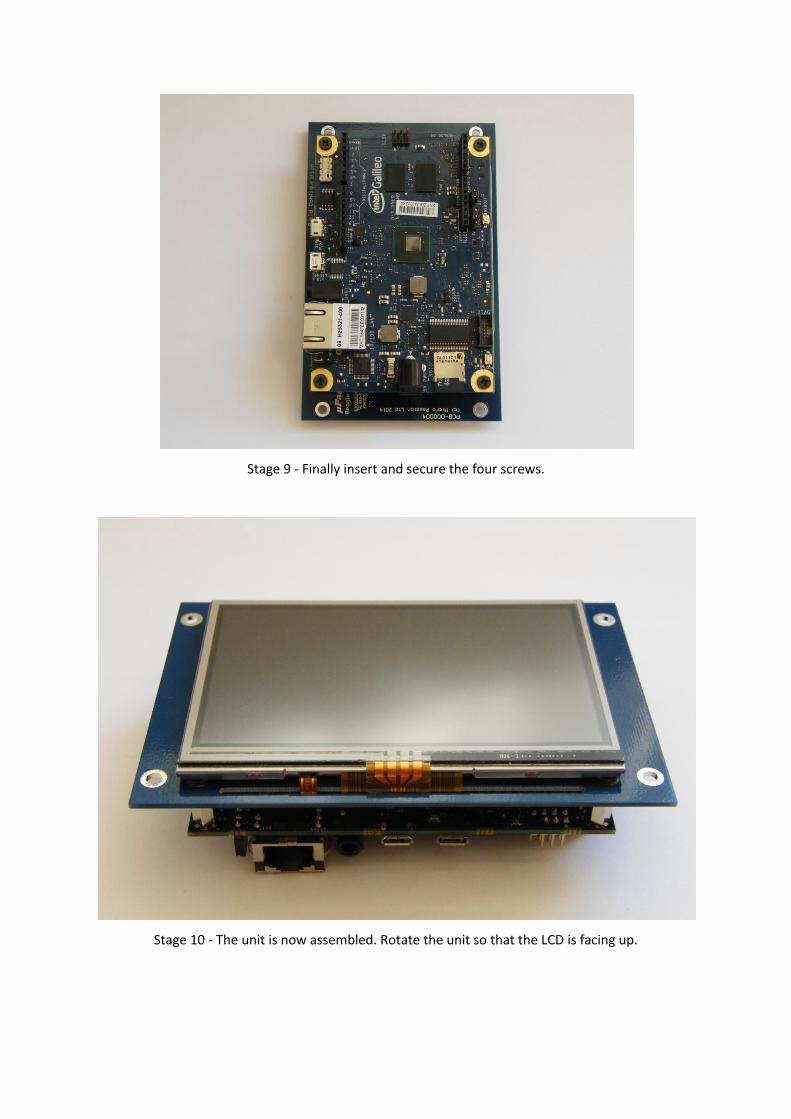
Stage 9 - Finally insert and secure the four screws.
Stage 10 - The unit is now assembled. Rotate the unit so that the LCD is facing up.
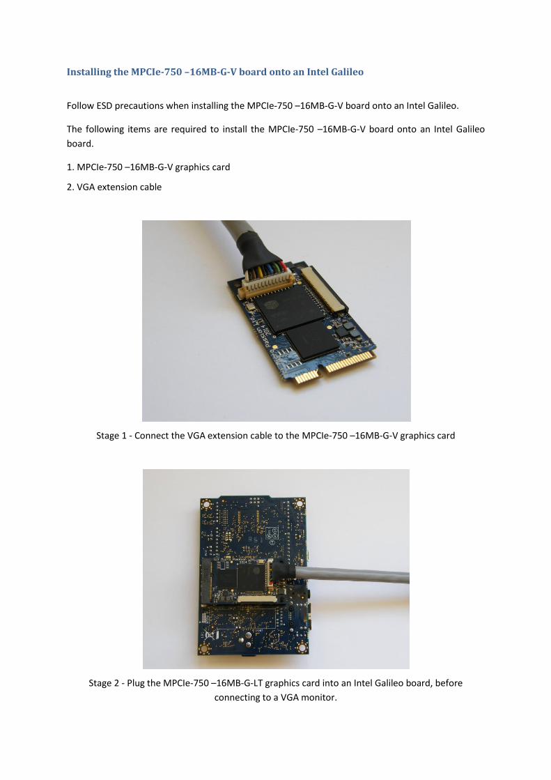
Installing the MPCIe-750 –16MB-G-V board onto an Intel Galileo
Follow ESD precautions when installing the MPCIe-750 –16MB-G-V board onto an Intel Galileo.
The following items are required to install the MPCIe-750 –16MB-G-V board onto an Intel Galileo
board.
1. MPCIe-750 –16MB-G-V graphics card
2. VGA extension cable
Stage 1 - Connect the VGA extension cable to the MPCIe-750 –16MB-G-V graphics card
Stage 2 - Plug the MPCIe-750 –16MB-G-LT graphics card into an Intel Galileo board, before
connecting to a VGA monitor.

Demo software Some demonstration software has been put together that shows how the MPCIe-750 –16MB-X can
be used in both an Arduino, and QT development environment in conjunction with the Intel Galileo
board. Both environments rely on booting the Intel Galileo board from an SD card containing a
customised kernel, and YOCTO root file system.
The following downloads are available:
Download URL Description
http://www.micropassion.co.uk/downloads/arduino-1.5.3.1.zip
A Windows Arduino development environment for the Intel Galileo board including MPCIe-750 graphics library and demo applications
http://www.micropassion.co.uk/downloads/galileo-mpcie750-yoctofull-qt-touchV100.tar.bz2
YOCTO root file system including QT librarys, demo applications, and touch screen support.
http://www.micropassion.co.uk/downloads/Galileo-MPCIe750MicroSDFATPartitionV100.zip
Customised Intel Galileo Linux kernel and GRUB configuration including support for the MPCIe-750 graphics card.
http://www.micropassion.co.uk/downloads/galileo-mpcie750-yoctofull-qt-touch-sdimageV100.zip
A raw image of a 2GB micro SD card, partition, and containing Linux kernel, and YOCTO root file system.
SD Card creation Method 1
Purchase a pre-image micro SD Card from Micro Passion. Contact [email protected] for
details.
SD Card creation Method 2
To create an SD card using the raw SD card image use the following steps.
1. In a Linux environment attach an SD card of at least 2GB in size.
2. In a console type, "dmesg | tail", and note down the name of the micro SD card. In the
following example the sdcard drive name is "/dev/sdc"
[ 4528.160460] sd 3:0:0:1: [sdc] 3854336 512-byte logical blocks: (1.97 GB/1.83 GiB)
[ 4528.166631] sd 3:0:0:0: [sdb] Attached SCSI removable disk
[ 4528.173231] sd 3:0:0:1: [sdc] Write Protect is off
[ 4528.173236] sd 3:0:0:1: [sdc] Mode Sense: 03 00 00 00
[ 4528.185294] sd 3:0:0:1: [sdc] No Caching mode page present
[ 4528.185412] sd 3:0:0:1: [sdc] Assuming drive cache: write through
[ 4528.222988] sd 3:0:0:1: [sdc] No Caching mode page present
[ 4528.223077] sd 3:0:0:1: [sdc] Assuming drive cache: write through
[ 4528.226472] sdc: sdc1 sdc2
[ 4528.262808] sd 3:0:0:1: [sdc] No Caching mode page present
[ 4528.262904] sd 3:0:0:1: [sdc] Assuming drive cache: write through
[ 4528.263002] sd 3:0:0:1: [sdc] Attached SCSI removable disk
3. In a console type, "wget http://www.micropassion.co.uk/downloads/galileo-mpcie750-
yoctofull-qt-touch-sdimageV100.zip" to download the raw SD card image.
4. In a console type, "unzip galileo-mpcie750-yoctofull-qt-touch-sdimageV100.zip" to extract
the raw SD card image
5. In a console type, "dd if=./galileo-mpcie750-yoctofull-qt-touchV100.sdimage of=/dev/sdc" to
copy the raw SD card image to a SD card. IMPORTANT: replace /dev/sdc with the drive
identified in step 2. Mistakes with the dd command will destroy data.
6. Once the transfer is complete, remove the SD card and plug it into the Intel Galileo board.
GRUB configuration for MPCIe-750
The default GRUB configuration is setup for the 4.3" LCD on the LCD430-G-R LCD module. The
resolution of this panel is 480x272. To setup the MPCIe-750 card to drive VGA resolutions see the
following steps.
1. Mount the SD card created above in either Linux or Windows.
2. Navigate the "BOOTME" partition of the SD card and edit the file, "boot\grub\grub.conf "
3. Replace all instances of, "480x272" with the required VGA resolution. Some examples or
supported resolutions include, "640x480", "800x600", "1024x768", "1920x1080".
4. Save the file.
Arduino development environment
The Arduino development environment is based on the current Intel Galileo release (V1.5.3) with
the addition of a mPCIe750 graphics library. To use the Arduino development environment follow
the below steps.
1. Download the Arduino environment from,
http://www.micropassion.co.uk/downloads/arduino-1.5.3.1.zip
2. Extract the file to the root of a drive to ensure file path lengths are kept to a minimum
3. Enter the arduino-1.5.3.1 directory and launch arduino.exe
4. Insert the micro SD card created earlier into an Intel Galileo board and power the board. If
the Intel Galileo board is using the latest software the board will boot from the SD Card, and
display a login prompt on the display after approximately 60 seconds.
5. If the Intel Galileo board doesn't boot from the SD card the firmware may need to be
upgraded. This can be achieved by using the firmware update feature of the Arduino
environment. See the Intel Galileo getting started guide for details.
https://communities.intel.com/servlet/JiveServlet/downloadBody/21838-102-7-
25423/Galileo_GettingStarted_329685_005.pdf
6. Write an application and upload it to the Intel Galileo

Arduino demo applications
The Arduino development environment comes with a graphics library targeting the MPCIe-750
graphics card. The library is located in, "arduino-1.5.3.1\libraries\mPCIe750".
Two demo applications are included with the library.
Demo Application
Location Description
TFTBitmapLogo libraries\mPCIe750\examples\TFTBitmapLogo Demonstrates drawing a JPEG image to the display in random locations
TFTPong libraries\mPCIe750\examples\TFTPong An example of the classic Pong game that uses analogue inputs to move the paddle.
QT demo applications
The customised YOCTO root file system includes the QT graphics library and standard demo
applications. To test the QT demo applications follow the below steps.
1. Insert the micro SD card created earlier into an Intel Galileo board and power the board. If
the Intel Galileo board is using the latest software the board will boot from the SD Card, and
display a login prompt on the display after approximately 60 seconds.
2. If the Intel Galileo board doesn't boot from the SD card the firmware may need to be
upgraded. This can be achieved by using the firmware update feature of the Arduino
environment. See the Intel Galileo getting started guide for details.
https://communities.intel.com/servlet/JiveServlet/downloadBody/21838-102-7-
25423/Galileo_GettingStarted_329685_005.pdf
3. Once at the login prompt login with the user, "root" (Password is not required)
4. Navigate to, "/usr/bin/qtopia/demos"
5. Pick and launch a demo. E.g. type, "./spreadsheet/spreadsheet -qws"
Touch Screen Calibration
The customised YOCTO root file includes the touch screen library tslib. To calibrate the touch screen
follow the below steps.
1. At the login prompt login with the user, "root" (Password is not required)
2. type, "ts_calibrate"
3. Touch the cross hairs in turn.
~ Happy Developing ~
We are always interested to find out what exciting things you have used our products for and
feedback on how we can improve.
Recommended


![EMB-RasPI-130x-Cape Datasheet · Introduction 1 Introduction The EMB-RasPI-130x-Cape is an extension board for both EMB-LR1301-mPCIe [1] and EMB-LR1308-mPCIe, specially designed for](https://img.dokumen.tips/doc/110x75/5f20a68c09341421ba2e5dc3/emb-raspi-130x-cape-introduction-1-introduction-the-emb-raspi-130x-cape-is-an-extension.jpg)