Modular Platforms for
Early Production / Full Field
Applications
Mirco BUSETTO a,1, Marco ZENNARO a ,
Andrea RIMOLDI b and Carmine PALUMBO b
a Fincantieri Oil&Gas
b Eni R&D
Abstract. Previous works have shown that the use of floating modular platforms
(FMP) can represent a valid approach to the development of human activities at sea, near and off shore, both in civil/residential or industrial applications.
In particular, FMP technology provides a solution that allows the development of
offshore fields in sequential stages. This will allows a shortening of the time for the First Oil, reducing the initial investment and starting to produce positive cash
flow from the beginning.
During the Early Production phase are furthermore gathered more information on the field that will allow a more accurate and precise planning of the Full Field
development by reducing the risks to the oil companies. In addition, modularity of
the solution allows a sequential implementation of the system in accordance with the field development, and a potential reuse and relocation of the facilities at the
end of the field.
This paper presents the results of a pre-feasibility study jointly developed by Fincantieri and Eni with the scope of evaluating, as alternative to conventional
FPSO concepts, an innovative flexible solution based on several modules
connected together to compose an Early Production platform expandable into a Full Field configuration at a later stage.
Keywords. Modularity, Floating Production
1. Introduction
The O&G market is dramatically changed compared to only a few years ago [1],
requiring for alternative business models and approaches to the exploitation of offshore
fields: one of these, is represented by the development of offshore fields in sequential
stages. This will allows a shortening of the time for the First Oil, reducing the initial
investment and starting to produce positive cash flow from the beginning.
During the Early Production (EP) phase are furthermore gathered more
information on the field that will allow a more accurate and precise planning of the Full
Field (FF) development by reducing the risks for the oil company.
The above business model requires however an analogous alternative design
approach in order to identify innovative floaters capable of modular extension in order
1 Mirco BUSETTO, Fincantieri Oil&Gas, Passeggio S.Andrea 6/A, 34123 Trieste, Italy; E-mail:

to allow a sequential implementation of the configuration in accordance with the field
development, and a potential reuse and relocation of the facilities at the end of the field.
This paper present the results of a prefeasibility study jointly developed by
Fincantieri and Eni for the application of Floating Modular Platforms (FMP)
technology to the exploitation of oil fields according to EP / FF concept.
2. Design Principles
The convenience for Oil Companies to split the project into two sequential phases (an
early production phases and a full field development stage) in order to speed up the
return of investment and dilute over time the Capex costs, poses technical and
economic constraints to the conventional FPSO concepts application, mainly related to
the design definition of the configuration and to the development schedule.
A solution based on a modular configuration, completely fabricated and assembled
on-shore and installed at site fully commissioned, is therefore considered a viable way
to face the above problems and to minimize costs and schedule.
According to the above considerations, Fincantieri has developed and patented [2],
[3] a innovative concept based on a modular system, named Floating Modular
Platforms (FMP), purposely conceived for installation in mild environment (West
Africa) and compatible with a delivery in two stages: a small platform as early
production plant and an enlarged configuration suited for the full field development.
The concept has been developed for the specific application on the basis of the
following main principles:
to be split in several, of size compatible with construction in conventional
marine yards, fitted with their own parts of the process plant;
to allow the towing of the modules, arranged in sub-assemblies with two or
three elements;
to allow the offshore coupling and permanent connection of the modules;
to provide operating reliability and performances similar or not lower of the
ones of conventional floating systems;
to allow mooring through conventional systems;
to allow offloading to shuttle tanker moored to the platform.
The geometrical shape and dimensions of the structures have been defined
accounting for the following operating and functional requirements:
to provide adequate deck area for process plants accommodation;
to allow floatation and stability performances during towage in a free floating
configuration;
to ensure adequate safety level against potential collision or accidental
damages;
to provide adequate storage capacity for oil and water ballast.
3. Platform Description
The platform is composed of several floating modules, with identical hull configuration,
accommodating on deck the various process plants. The modules are joined together,

partly at the onshore yard, partly at the installation site, with structural bracings and
permanent connecting elements, to form a rigid body.
The decks of the modules are also interconnected at the top level with passageways
and walkways to form a continuous working platform and with pipe racks to support
the interconnecting piping.
3.1. Single module
Each module (overall height 21.5 m) is composed of two main parts:
a lower hull, having a cylindrical shape with hexagonal base (side 23.0 m,
height 19.0 m, operative draft 12.0 m), which represent the floater and
accommodate the storage volumes;
an upper deck, again with an hexagonal base (side 28.9 m, height 2.5 m),
accommodating the process and utility plant.
The typical geometry of the individual modules is reported in Figure 1.
Figure 1. Single module geometry
The hull of each module is subdivided into several compartments, devoted to oil
storage (abt 10000 cubic meters capacity), water ballast and technical rooms. The water
ballast compartments are located at the bottom and at periphery of the hull, to realize a
double bottom/side configuration.
The modules are connected together though a pair of structural links for each
interfacing side at deck level and two pairs of crossing bracings at hull level.
The internal volumes of the deck and of the hull will be accessible through internal
stairs, whilst watertight compartments will be accessible for extraordinary maintenance
only through manholes.
3.2. Overall platform
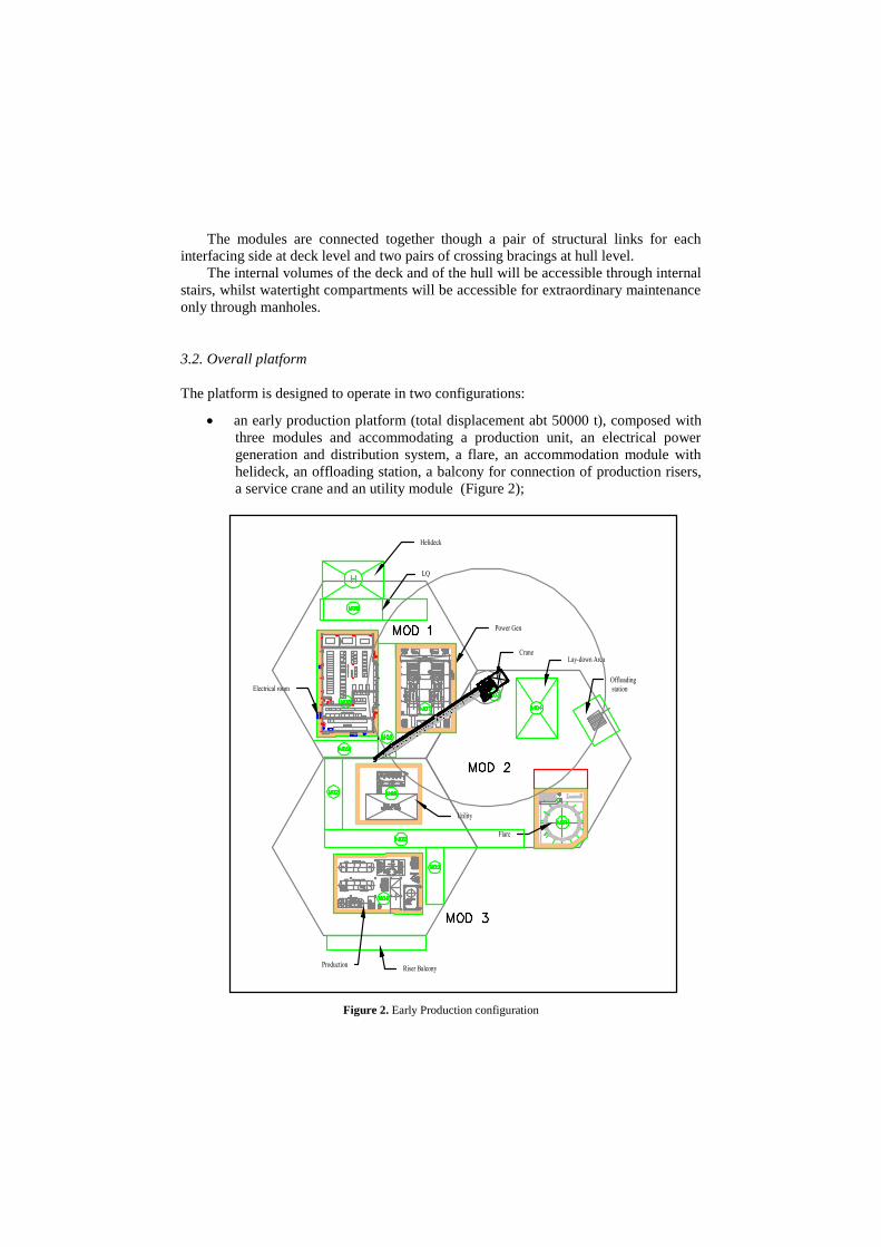
The platform is designed to operate in two configurations:
an early production platform (total displacement abt 50000 t), composed with
three modules and accommodating a production unit, an electrical power
generation and distribution system, a flare, an accommodation module with
helideck, an offloading station, a balcony for connection of production risers,
a service crane and an utility module (Figure 2);
Figure 2. Early Production configuration

a full field production platform (total displacement abt 150000 t), composed of
nine modules and accommodating an extended oil production and power
generation plant, LP/HP gas compression systems, sea water and produced
water/sand treatment system, a TEG system, a second crane and new utility
packages (Figure 3).
Figure 3. Full Field configuration
4. Analyses and Checks
The analyses of the platform have been developed to a level suitable to confirm the
feasibility of the concept in respect to the temporary and permanent working conditions
(construction, transportation, installation and operations at site) and to prove that the
selected configuration may operate under the expected extreme conditions, with
performances comparable with the ones of other more conventional floaters.
The performed analyses covered the following aspects:
Hydrostatic behaviour of single module and of assembled platforms
Hydrodynamic behaviour of the assembled platforms
Preliminary identification of mooring system
Check of structural strength of connection elements
4.1. Hydrostatic analyses
Hydrostatic analyses are aimed to identify the static configuration of the single
modules and of temporary sub-assemblies (three modules joined together) during the
towing and installation phase and to evaluate the stability performances of the overall
platform in free floating condition.

The most critical conditions in terms of hydrostatic stability are represented by the
floatation of the single modules before sub-assembling, in particular for the module
having the maximum topside weight. Stability diagrams, in term of righting and
heeling arms, have been determined for a wind speed of 50 m/s considering a topside
exposed area for the whole width of the platform up to a height of 4.0 m above the deck
(Figure 4).
Figure 4. Intact Stability - Module n°9
The results confirms that the stability requirements, both in intact and damaged
conditions are always in compliance with statutory requirements [4] with large safety
margins.
4.2. Hydrodynamic analyses
Hydrodynamic analyses were carried out, for the operative constant draft of 12.0 m,
with two main purposes:
To determine the dynamic behaviour (motions) of the platform;
to determine the maximum expected acceleration of the process plant, as basis
of comparison with other floating system and of judgement about system
operability.
The following meteo-marine data, typical of West Africa scenarios, have been
assumed for the calculations:
Tr (years) Hs (m) Tp (s)
1 2.5 14 - 16 - 18
100 3.2 15 - 18 - 20
A Jonswap spectrum type with peakdeness factor = 5 has been considered.
0
0,5
1
1,5
2
2,5
3
3,5
0 10 20 30 40 50 60 70
Gz
/ H
A (
m)
angle (deg)
stability diagram
GZ
HA

Wind speed of 36 m/s (1 min gust) and current speed of 0.7 m/s have been
considered associated to 100 year storm wave condition.
Diffraction analysis has been performed to derive platform load and motion
RAO's, hydrodynamic added mass and potential damping coefficients, wave drift
coefficients [5]. Platform motion (sea-keeping) and mooring analysis have been
performed with ORCAFLEX software, which analyses floating multi-bodies,
connected each other or moored to seabed or fixed points, in time domain. The
software allows to derive time series of each parameter of interest and evaluate
statistical data (mean value, standard deviation, response period, maximum and
minimum observed and calculated value).
The results indicate that the platform, both in its early production and full field
configuration, exhibits relatively low motions, with similar behaviour in roll and pitch.
As concerns the acceleration at the process topside, they have been computed for the
centre of gravity of all the main packages.
Tables 1 and 2 present, for two significant points (center of gravity of the overall
platform and of the most peripheral topside package) and two heading for the envelope
of extreme sea states, the most probable maximum (MPM) values calculated for the FF
platform compared with the ones obtained for two traditional ship shaped FPSO having
similar storage capacity in similar operative scenarios.
Table 1. Motions and accelerations comparison: = 0 deg
Vessel Point Xp
(m)
Zp
(m)
pitch
(deg)
Axp
(m/s2)
Azp
(m/s2)
FPSO 1 5C 2.12 1.84 1.90 0.21 0.20
FPSO 2 5C 2.09 1.76 2.00 0.20 0.19 FF platform 5C 1.80 2.34 2.28 0.19 0.32
FPSO 1 2-M01 1.71 3.66 1.90 0.17 0.67
FPSO 2 2-M01 1.67 3.90 2.00 0.16 0.70 FF platform 2-M01 1.42 4.20 2.28 0.15 0.86
Table 2. Motions and accelerations comparison: = 90 deg
Vessel Point Xp
(m)
Zp
(m)
roll
(deg)
Axp
(m/s2)
Azp
(m/s2)
FPSO 1 5C 2.90 3.10 11.10 0.59 0.75 FPSO 2 5C 4.10 3.40 7.00 0.54 0.78
FF platform 5C 2.00 2.70 3.31 0.27 0.52
FPSO 1 2-M01 4.50 3.66 11.10 1.18 0.90 FPSO 2 2-M01 5.85 3.75 7.00 0.63 0.87
FF platform 2-M01 1.62 2.80 3.31 0.28 0.60
The obtained values are not too different, thus confirming the good behaviour of
the proposed concept.
4.3. Mooring system
A preliminary arrangement of the mooring system has been identified, as compromise
between the resulting platform motions (mean excursions) and mooring legs tensions.
The design of mooring system, for the selected operative scenario, is strongly
affected by the wind loads which depend from the exposed area and from wind speed.

The analyses, developed according to API rules [6], accounted for both intact
configuration of the mooring pattern and damaged condition (one leg broken). The
selected mooring pattern (deep water condition) is composed of ten lines (chain, wire
rope and anchor), set as per Figure 54: six lines are positioned on the windward side,
four lines on the opposite side.
Figure 5. Mooring pattern
The following characteristics of each leg have been selected:
Windward Leeward
Wire rope (spiral 70 mm) 1700 m 1700 m
Chain section (R3 68 mm) 1500 m 500 m
Total length 3200 m 2200 m
Pretension 415 kN 505 kN
Anchor Stevin type 15 t 15 t
After a simplified sensitivity analysis in order to identify the most critical mooring
system performances, the results of the final simulations in 3h storm duration have
identified MPM values (evaluated with Rayleigh formulation) of mooring line tension
below the safety factors (respectively 1.67 and 1.25 for intact and damaged conditions),
proving the adequateness of selected configuration.
4.4. Structural checks of connection elements
For structural analysis of connection members among the modules, a “composite”
model has been developed, including nine separate modules and related connection
members. Each separate module is modelled as a rigid floating body in 6 d.o.f, while
connection members between two modules are modelled by means of rigid beams
= 90°
= 0°

(having mass and axial/bending stiffness) connecting modules at deck level and hull
sides (Figure 6).
Figure 6. Connections structural model
Connection elements have been checked in 100 years storm extreme meteo
condition, for different headings and range of periods: MPM values for axial, shear and
bending moment have been calculated and consequent Von Mises stress evaluated.
The maximum loads resulting at the deck and hull level are compatible with
tubular bracings having a diameter of 2.0 m with a thickness of 50 mm.
5. Installation Procedures
As previously described, the platform is designed to be fully developed in two stages:
An early production configuration, composed of three modules;
A full field production configuration, composed of nine modules.
To comply with the above field development scheme, the platform fabrication
passes through the following main steps:
Fabrication of the individual modules, complete with the relevant parts of the
process plant;
Assembly of the first three modules, to form the early production platform;
Transportation and installation at site and completion of the early production
phase;
Assembly of two series of three modules to form two large sub-units;
Transportation in the area of the two sub-units;
Connection of the two sub-units, to form the extended full field platform;
Installation of the extended platform and joining to the early production plant.
6. Conclusions
The project has identified a promising and reliable solution for oil production in milder
area and in particular for application in West Africa.
The proposed configuration combines the advantages of a conventional FPSO with
the flexibility offered by a modular system, which enhance its profitability operating in
a first life stage as early production platform and in a second life as full field
development.
The proposed solution provided the following main advantages;
to be fabricated in a conventional naval yards;
to allow the full assembly and integration at the construction site;
to allow transportation by towing;
to minimize the installation and offshore commissioning schedule and costs;
to allow the expansion of the plant without removal of the previous one and
with minimum production downtimes;
to allow the use of conventional vessels to assist in the marine operations.
The design activities have investigated the most crucial issues of the concept,
ensuring its feasibility and the general compliances with the most recognised standards
and rules.
Regarding the economic aspects, the estimated costs are comparable with a typical
FPSO: however, it has to be highlighted the proposed FMP concept presents at a major
degree of flexibility during the asset development.
Further design activities are foreseen in order apply the innovative concept to other
production scenario.
References
[1] M. Busetto, L. Ambrosio: Modular Platforms for Near/Off Shore Applications, Offshore Mediterranean
Conference , Ravenna (Italy), 2017 [2] European Patent EP 2 691 289: Modular Semi-Submersible Structure and Method for Making Such
Structure, 24/12/2014 Bulletin 2014/52
[3] Italian Patent 102015000027956: Modular Semi-Submersible Structure for Floating Offshore Wind Turbine, 26/06/2015
[4] IMO: MODU CODE Code for the Construction and Equipment of Mobile Offshore Drilling Units, 2009
[5] DNV–RP-C205: Environmental conditions and environmental loads, October 2010
[6] API-RP-2SK: Design and Analysis of Stationkeeping Systems for Floating Structures, October 2005
Recommended