GDS Corp.
1245 Butler Road League City, Texas 77573
409-927-2980 409-927-4180 (Fax) www.gdscorp.com
MODBUS Wiring Recommendations
For Systems Using GDS Corp Controllers, Gas and Flame Detectors

GDS Corp MODBUS Wiring Recommendations, Revision 1.1
GDS Corp Page 2 [email protected]
CAUTION: FOR SAFETY REASONS THIS EQUIPMENT MUST BE OPERATED AND
SERVICED BY QUALIFIED PERSONNEL ONLY. READ AND UNDERSTAND INSTRUCTION
MANUAL COMPLETELY BEFORE OPERATING OR SERVICING.
ATTENTION: POUR DES RAISONS DE SÉCURITÉ, CET ÉQUIPEMENT DOIT ÊTRE UTILISÉ,
ENTRETENU ET RÉPARÉ UNIQUEMENT PAR UN PERSONNEL QUALIFIÉ. ÉTUDIER LE
MANUE D’INSTRUCTIONS EN ENTIER AVANT D’UTILISER, D’ENTRETENIR OU DE
RÉPARER L’ÉQUIPEMENT.
REVISION HISTORY
Revision 1.0 6/29/13 Initial version
Revision 1.1 7/10/15 Added Appendix B for Redundant Port Configuration on C64 Controller
Copyright © 2015 GDS Corp. All Rights Reserved
P/N 1200-0857-02

GDS Corp MODBUS Wiring Recommendations, Revision 1.1
GDS Corp Page 3 [email protected]
CONTENTS
1 SAFETY INFORMATION ................................................................................................................................................. 5
2 GENERAL INFORMATION .............................................................................................................................................. 6
3 MODBUS SYSTEM LAYOUT ........................................................................................................................................... 7
4 MODBUS POWER AND SIGNAL WIRING ....................................................................................................................... 8
MODBUS SIGNAL CABLE RECOMMENDATIONS ................................................................................................................... 9
MODBUS POWER DISTRIBUTION ..................................................................................................................................... 9
MODBUS SIGNAL TERMINATION .................................................................................................................................... 10
WIRING SUMMARY ....................................................................................................................................................... 11
5 MODBUS DEVICE ADDRESSING .................................................................................................................................. 12
6 MODBUS MASTER DEVICES ........................................................................................................................................ 13
C1 PROTECTOR CONTROLLER .......................................................................................................................................... 13
Slave ID ................................................................................................................................................................ 14
Slave Baud ........................................................................................................................................................... 14
Master Timeout ................................................................................................................................................... 14
Master Poll Rate .................................................................................................................................................. 14
C64 PROTECTOR CONTROLLER ........................................................................................................................................ 15
FUnction ............................................................................................................................................................... 16
Baud RATE ........................................................................................................................................................... 16
Timeout ................................................................................................................................................................ 16
POLL DELAY .......................................................................................................................................................... 16
7 MODBUS SLAVE DEVICES ........................................................................................................................................... 17
GASMAX II GAS MONITORS ......................................................................................................................................... 17
8 MODBUS SYSTEM COMMISSIONING RECOMMENDATIONS ....................................................................................... 19
BEFORE APPLYING POWER: ............................................................................................................................................. 19
AFTER POWER-UP ........................................................................................................................................................ 19
9 APPENDIX A – C64 MIXED MODBUS / ANALOG .......................................................................................................... 21
10 APPENDIX B – C64 REDUNDANT PORT CONFIGURATION ........................................................................................... 22

GDS Corp MODBUS Wiring Recommendations, Revision 1.1
GDS Corp Page 4 [email protected]
Table of Figures Figure 2-1: Simplified MODBUS Message Protocol ....................................................................................................... 6
Figure 3-1: Recommended MODBUS Topologies .......................................................................................................... 7
Figure 3-2: MODBUS Topologies to Avoid ..................................................................................................................... 7
Figure 4-1: MODBUS Power and Signal Wiring .............................................................................................................. 8
Figure 4-2: MODBUS Signaling ....................................................................................................................................... 8
Figure 4-3: MODBUS Power Calculation 1 ..................................................................................................................... 9
Figure 4-4: MODBUS Power Calculation 2 ................................................................................................................... 10
Figure 4-5: MODBUS Power Calculation 3 ................................................................................................................... 10
Figure 5-1: MODBUS Addressing Recommendation.................................................................................................... 12
Figure 5-2: Example MODBUS Master / Slave Relationship ........................................................................................ 12
Figure 6-1: C1 Protector Controller Main I/O Board #10-0142 ................................................................................... 13
Figure 6-2: C1 Protector Communications Setup Menu .............................................................................................. 14
Figure 6-3: C64 Protector Controller Main I/O Board #10-0331 ................................................................................. 15
Figure 6-4: C64 Communications Setup Menu ............................................................................................................ 16
Figure 7-1: GASMAX II MODBUS Wiring ...................................................................................................................... 17
Figure 7-2: GASMAX II MODBUS Wiring Junction Box ................................................................................................. 17
Figure 7-3: GASMAX II RS-485 Communications Menu ............................................................................................... 18
Figure 9-1: C64 Mixed MODBUS / Analog ................................................................................................................... 21
Figure 10-1: Redundant Communications Using Dual Comm Ports ............................................................................ 22

GDS Corp MODBUS Wiring Recommendations, Revision 1.1
GDS Corp Page 5 [email protected]
1 SAFETY INFORMATION
Important – Read Before Installation
Users should have an understanding of basic electrical and electronic maintenance and installation procedures
before installing or operating MOBDUS systems. Additional information is available in the individual operational
and user’s manuals for equipment described in the document. Always read and understand the following
WARNINGS prior to use.
WARNINGS
• MODBUS power distribution systems carry +24V with the ability to provide significant current. Do not
short power and ground wiring.
• Make sure that power is OFF before cutting or splicing power or signal cable.
• Do not interchange MODBUS power and signal wiring. Doing so WILL result in damage to equipment that
is not covered under factory warranty.
• Always make sure to visually inspect wiring before applying power.
• Never run low voltage (+24V) and high voltage (+110 AC or higher) in the same conduit
• Always use shielded cable with the proper impedance for MODBUS signal wiring. Shielding for power
distribution cable is not required but is recommended.
• Always keep MODBUS signal cable away from high powered motors, compressors, fluorescent lighting
and other sources of high voltage radio frequency interference (RFI)
• Always perform a complete end-to-end test of any gas detection system (MODBUS or otherwise) before
relying on the system for personnel protection or equipment monitoring.

GDS Corp MODBUS Wiring Recommendations, Revision 1.1
GDS Corp Page 6 [email protected]
2 GENERAL INFORMATION
MODBUS is a popular means of connecting electronic devices in industrial applications. Hardware and software
solutions for devices and cabling are reliable and widely available; the protocol is simple and easy to understand
and troubleshoot; and in many applications, daisy-chain, point-to-point wiring is less costly to install and maintain
than the ‘home run’ wiring required for traditional 4-20mA current loops.
For purposes of this manual, the term “MODBUS” will refer to MODBUS protocol transmitted over RS-485 two-wire
connections. MODBUS/TCP or MODBUS protocol over alternative physical layers will not be discussed.
Every MODBUS loop has one MASTER device and up to 240 SLAVE devices. At the start of each cycle, the master
transmits a message ‘packet’ [A] that contains the address of the first slave device and the MODBUS registers
requested. Every device on the loop receives and processes the request; only the slave device with the matching
address transmits a response packet [B] with the requested information. The master device monitors the loop and
signals a ‘communications error’ if the return message contains errors or is not received within a fixed time.
Figure 2-1: Simplified MODBUS Message Protocol
MODBUS master device sends and receives data from each slave device individually, starting with device #1 and
continuing to request data from each subsequent device until the last device has been queried; this process then
repeats as long as the master is active.
Several parameters are important to understand: BAUD RATE is the speed at which data is transmitted across the
loop; TIMEOUT is the length of time a master will wait for a reply before moving to the next device; POLL RATE is
the length of time between each transmission, and LOOP LATENCY is the maximum time between data requests to
any one slave device. For GDS Corp equipment, BAUD RATE is always 9600 baud, TIMEOUT and POLL RATE are
user-adjustable settings, and LOOP LATENCY is determined by the POLL RATE and number of devices on the loop.
1 2 3
1 2 3
Master sends Data Request (Device “2”, Register “31001?”) heard by all devices
Only Device “2” answers with Reply (Device “2”, Register 31001 = 202)
MODBUS Slave Devices MODBUS Master Device
[A]
[B]

GDS Corp MODBUS Wiring Recommendations, Revision 1.1
GDS Corp Page 7 [email protected]
3 MODBUS SYSTEM LAYOUT
MODBUS communication is based on data packets that are transmitted between master and slave devices. Data
transmission across physical wires is subject to interference from external sources (lightning, fluorescent lamps) as
well as ‘reflections’ that occur when the transmitted signals reach the end of a wire segment. To minimize
reflections, MODBUS devices should be wired in a ‘daisy-chain’ configuration with a single data path running from
device to device.
Figure 3-1: Recommended MODBUS Topologies
Configurations that include the ‘star’ and ‘ring’ layouts should be avoided. Star topology allows multiple reflections
to occur on the network; under certain conditions, these reflections can constructively interfere (“add”) resulting
in signal spikes that can overwhelm subsequent transmissions or damage components. Ring networks have similar
problems. However, the C64 Protector Controller has the ability to connect two separate communications ports in
a “pseudo-ring” configuration that provides redundancy in the event one of the data communications wires is cut.
Figure 3-2: MODBUS Topologies to Avoid
Daisy Chain “Loop” (Recommended) Backbone with Short Stubs (Workable)
Star (Avoid) Ring (Avoid)

GDS Corp MODBUS Wiring Recommendations, Revision 1.1
GDS Corp Page 8 [email protected]
4 MODBUS POWER AND SIGNAL WIRING
Most MODBUS loop wiring includes both power and signal wiring, so at a minimum four conductor cable is
required. MODBUS data signals must be run using twisted shielded pair wire. Power and ground wires can also be
twisted shielded, but this is not a requirement.
Figure 4-1: MODBUS Power and Signal Wiring
Figure 4-1 shows a typical GDS Corp MODBUS wiring scheme. Power (“+24”) and power ground (“G”) are sourced
by the MODBUS master device, typically a C1 or C64 Protector Controller. MODBUS signals are labeled “A” and “B”
per industry standards. Power and signal wiring starts at the master device and runs to each slave device.
MODBUS uses a low voltage differential signaling protocol (see Fig. 4-2). “Differential” signals move in opposite
directions – when “A” rises, “B” falls, and vice-versa, and the receiving device measures the difference between
the two signals instead of comparing a single signal to a reference ground. Differential signaling is significantly
better at reducing interference and increasing link length. Note that even though MODBUS RS-485 is considered a
“2-wire” connection, a common ground reference is still required for reliable operation.
Figure 4-2: MODBUS Signaling
4
+24
+24 G
G “A”
“A” “B”
“B”
A
B
A
B
MODBUS Master
MODBUS Slave(s)
“Low Voltage Differential Signaling”
+24V +24V
Common Ground Reference
MODBUS
Transceiver
MODBUS
Transceiver
DATA OUT DATA IN

GDS Corp MODBUS Wiring Recommendations, Revision 1.1
GDS Corp Page 9 [email protected]
MODBUS SIGNAL CABLE RECOMMENDATIONS
MODBUS wiring should be selected such that the characteristic AC impedance (“Z”) of the cable matches the
impedance of standard transceiver chips. The most common RS-485 twisted pair has an impedance of 100 ohms.
Cables designed specifically for RS-485 include Belden RS-485 cable (9841-9844) or Alpha Wire (6222-6230). Cables
with lower impedance will result in higher current draw from the MODBUS transceiver chips, reducing signal
integrity margins and increasing power consumption. As the selection of cable is based on a number of
considerations, please contact GDS Corp for more information.
MODBUS POWER DISTRIBUTION
When designing a MODBUS system, consideration must be given
to the current and voltage distribution along the wiring for both
steady-state current draw and initial power-on surge current. For
example, the length of cable between the master and first slave
device must carry current to power all devices on the loop,
whereas the cable between the next-to-last and last device need
only carry current for that one device. Calculations should always be made regarding conductor size to ensure that
sufficient voltage is available at the end of the loop during start-up and steady state. Note that gas detectors are
constant power devices, so as voltage drops, current increases.
Figure 4-3: MODBUS Power Calculation 1
Figure 4-3 shows an example MODBUS system with a single Controller and five GASMAX II + GDS-IR devices spread
over a loop totaling 600 feet (1200 wire-feet) in length. Each device requires 9 watts of steady state power, and
the wire used is #18 ga, 0.6 ohms per 100 feet. Calculations show that with steady state power consumption the
minimum voltage at the end of the loop will be lower than the specified 18V requirement. Furthermore, this
configuration does NOT take into account the voltage drop during initial power up, nor does it allow for future
voltage reductions due to changes in wiring resistance or 24V power supply.
Device Power V(min)
GASMAX II Toxic Sensor 4 W 12V
GASMAX II Bridge Sensor 5 W 12V
GASMAX II + GDS-IR 9 W 18V
SharpEye Flame Detector 3.5W 18V
200 ft. 50 ft. 50 ft. 50 ft. 250 ft.
9 W 9 W 9 W 9 W 9 W Master
45 W / 1.9A 2.4 Ω
(-4.6V) 19.4V
36 W / 1.8A 0.6 Ω
(-1.1V) 18.3V
27 W / 1.5A 0.6 Ω
(-0.9V) 17.4V
18 W / 1.0A 0.6 Ω
(-0.6V) 16.8V
9 W / .53A 3.0 Ω
(-1.6V) 15.2V
+24V +15.2V

GDS Corp MODBUS Wiring Recommendations, Revision 1.1
GDS Corp Page 10 [email protected]
If #14 gauge wire were to be specified for the system (0.25 ohms per 100 feet), under steady state conditions the
voltage at the end of the loop will be approximately +20.8V. In addition, allowing for power-on surge current
(typically 1.5x steady state) will result in +19.2V being present at final device, a value comfortably higher than the
GASMAX + GDS-IR minimum voltage (Vmin) of +18V.
Figure 4-4: MODBUS Power Calculation 2
To further improve this situation, the GDS-IR contains a ‘random-delay-power-up’ circuit that maintains the IR
source in the ‘off’ condition for a variable amount of time immediately after power is applied. This spreads out the
inrush surge and reduces the maximum amount of current needed to bring all the GASMAX monitors online.
Finally, Figure 4-5 shows a system with 5 GASMAX II hydrogen sulfide monitors on a similar 600 ft. loop. The lower
power consumption of the GASMAX II toxic detector, combined with the lower Vmin of +12V allows for the use of
#18 ga wire (0.6 ohms/100 ft.) while maintaining excellent voltage margin at the end device.
Figure 4-5: MODBUS Power Calculation 3
MODBUS SIGNAL TERMINATION
The last MODBUS device in each daisy-chain should have a ‘termination resistor’ installed across the MODBUS
signal lines to reduce signal reflection. All GDS Corp MODBUS slave devices include a jumper-select option to
connect the termination resistor. See the MODBUS section of each device for more details.
200 ft. 50 ft. 50 ft. 50 ft. 250 ft.
9 W 9 W 9 W 9 W 9 W Master
45 W / 1.9A 1 Ω
(-1.9V) 22.1V
36 W / 1.6A 0.25 Ω (-0.4V) 21.7V
27 W / 1.2A 0.25 Ω (-0.3V) 21.4V
18 W / .84A 0.25 Ω (-0.2V) 21.2V
9 W / .42A 1.0 Ω
(-0.4V) 20.8V
+24V +20.8V
100 ft. 100 ft. 100 ft. 100 ft. 200 ft.
4 W 4 W 4 W 4 W 4 W Master
20 W / 0.8A 1.2 Ω (-1V) 23.0V
16 W / 0.7A 1.2 Ω
(-0.8V) 22.2V
12 W / 0.5A 1.2 Ω
(-0.6V) 21.6V
8 W / .37A 1.2 Ω
(-0.44V) 21.1V
4 W / .19A 2.4 Ω
(-0.45V) 20.6V
+24V +20.6V

GDS Corp MODBUS Wiring Recommendations, Revision 1.1
GDS Corp Page 11 [email protected]
WIRING SUMMARY
When planning your MODBUS power and signal distribution system, keep these important notes in mind:
• Always use twisted shielded pair for MODBUS signals, and always provide appropriately sized power wire and
verify correct voltage at the end device in the chain.
• Accidentally swapping MODBUS and Power wiring WILL DAMAGE the equipment. Failures and damage due to
wiring errors are not covered under factory warranty.
• When local power is being supplied to a MODBUS device, make sure to connect a ground wire between the
master device DC power supply common and the local power DC supply common. Do not depend on Earth
ground for a common reference.
• Swapping MODBUS “A” and “B” will not damage the MODBUS device, but will result in communication errors
• Always make sure the last device in the daisy-chain has the termination resistor jumper set ON.

GDS Corp MODBUS Wiring Recommendations, Revision 1.1
GDS Corp Page 12 [email protected]
5 MODBUS DEVICE ADDRESSING
All slave devices on the same MODBUS chain must be assigned a unique address between 1 and 240. Since the
factory default address for GASMAX devices is “1”, GDS Corp recommends starting any sequence of addresses with
a value of “10” or higher to make certain that a replacement device accidentally installed on a loop with the
default address would not conflict with an existing device. Addresses are not specified for a master device.
For devices with multiple master ports, it is possible to reuse the same addresses on the second loop. However,
due to the probability of confusion, GDS Corp recommends assigning unique addresses to all MODBUS slave
devices in any system, irrespective of their assigned loop.
Figure 5-1: MODBUS Addressing Recommendation
Often a single device can have multiple ports that act as master or slave. In Figure 5-2, the C1 Protector
Controller’s “Comm 1” master port is connected to three GASMAX gas monitors, while the C1’s “Comm 2”slave
port is polled by the CR16/32, acting as master on the second loop.
Figure 5-2: Example MODBUS Master / Slave Relationship
“10” “11” “12” “25”
“30” “31” “32” “45”
COMM 3
MODBUS Master
COMM 4
MODBUS loop #1 – addresses 10 to 25. Addresses 26-29 reserved for future use
MODBUS loop #2 – addresses 30 to 45. Addresses 46 – 240 reserved for future use
C64 Controller
“10” “11” “12”
C1 Controller
CR16/32
Rmt Display
“COMM 2”
(Slave Port)
Address “1”
“COMM 1”
(Master Port)
No address
“COMM 1”
(Master Port)
No address “COMM 1”
(Slave Port)
Address “11”

GDS Corp MODBUS Wiring Recommendations, Revision 1.1
GDS Corp Page 13 [email protected]
6 MODBUS MASTER DEVICES
C1 PROTECTOR CONTROLLER
The C1 Protector 16-channel Controller supports one MODBUS master port and one MODBUS slave port. Comm1
is normally used to communicate with remote GASMAX gas monitors, while Comm 2 is used to communicate with
a remote DCS, PLC or CR16/32 Remote Display. See Figure 6-1 for a detailed description of MODBUS-related
hardware jumpers, indicators and connection terminals. Configuration shown is for 2-wire mode; 4-wire
configuration also available (see User’s Manual). Power for the MODBUS loop should be connected to the main
+24V supply (Use of TB2 9, 11 is not recommended).
Figure 6-1: C1 Protector Controller Main I/O Board #10-0142
1 3
2 4
11
10 12
1 3
2 4
11
10 12
1 3
2 4
11
10 12
MODBUS Transceiver Chips (4x)
(Socketed, field-replaceable if damaged)
MODBUS Slave Port Termination Resistors (2x)
(Socketed – should be installed if C1 is last device in MODBUS loop)
MODBUS 2-wire/4-wire jumpers
(Jumpers must be installed for 2-wire mode)
TX RX TX RX
COM 1 COM 2
MODBUS Data Indicator LEDs
TX LED = Transmitted data
RX LED = Received Data
MODBUS COMM 1 MASTER PORT
TB2-1 or TB2-5 = “A” TB2-3 or TB2-7 = “B”
(Duplicate connections for daisy-chain in/out)
TB1
TB2
TB1 AUX
MODBUS COMM 2 SLAVE PORT
TB2-2 or TB2-6 = “A” TB2-4 or TB2-7 = “B”
(Duplicate connections for daisy-chain in/out)

GDS Corp MODBUS Wiring Recommendations, Revision 1.1
GDS Corp Page 14 [email protected]
RS-485 serial MODBUS communication settings are found in COMM PORTS under the SYSTEM SETUP menu. The
following settings are user-programmable.
Figure 6-2: C1 Protector Communications Setup Menu
SLAVE ID – Sets the MODBUS address of the COMM 2 Slave Port.
SLAVE BAUD – Sets the COMM 2 data rate. Baud rate should be set for 9600 baud for optimal communications
with other GDS Corp products.
MASTER TIMEOUT – Determines how long the COMM 1 Master Port will wait for a reply to a sent message
before moving to the next channel. A longer timeout reduces communication errors, but increases loop latency if
one or more devices are missing from the loop.
MASTER POLL RATE – Determines how long the COMM 1 Master Port waits between transmissions. Faster poll
rates reduce loop latency but can cause communications errors is transmission rate exceeds the ability of the slave
device to receive the message and format and send a reply.
For more information on the options for MODBUS configuration, please review the C1 Protector Controller User’s Manual.

GDS Corp MODBUS Wiring Recommendations, Revision 1.1
GDS Corp Page 15 [email protected]
C64 PROTECTOR CONTROLLER
The C64 Protector Controller features two standard and two optional RS-485 MODBUS serial ports. Any port can
be configured to support master or slave functionality, as well as mimic mode connection to a remote display-only
controller. See Figure 6-1 for a detailed description of MODBUS-related hardware jumpers, indicators and
connection terminals. Configuration shown is for 2-wire mode; 4-wire configuration also available (see User’s
Manual).
Figure 6-3: C64 Protector Controller Main I/O Board #10-0331
2 4 10
1 3
2 4 10
1 3 11
12
MODBUS Transceiver Chips (4x)
(Socketed, field-replaceable if damaged)
MODBUS Data Indicator LEDs
TX LED = Transmitted data
RX LED = Received Data
MODBUS COMM 3 PORT
TB2-1 or TB2-5 = “A” TB2-3 or TB2-7 = “B”
(Duplicate connections for daisy-chain in/out)
MODBUS COMM 4 PORT
TB2-2 or TB2-6 = “A” TB2-4 or TB2-7 = “B”
(Duplicate connections for daisy-chain in/out)
MODBUS COMM 1 PORT
TB2-1 or TB2-5 = “A” TB2-3 or TB2-7 = “B”
(Duplicate connections for daisy-chain in/out)
MODBUS COMM 2 PORT
TB2-2 or TB2-6 = “A” TB2-4 or TB2-7 = “B”
(Duplicate connections for daisy-chain in/out)
RX TX RX TX
COM 1 COM 2
RX TX RX TX
COM 3 COM 4

GDS Corp MODBUS Wiring Recommendations, Revision 1.1
GDS Corp Page 16 [email protected]
Newer versions of the C64 Protector Controller include
dedicated wiring terminals for each installed communications
port that include a direct connection to system +24V and
common as well as connections for MODBUS “A” and “B”
signals. This allows the user to land their MODBUS wiring
without having to identify power and ground connection points.
A system with two communications ports would have two sets
of terminals shown; a system with both standard and optional
ports would have four terminal sets.
The four MODBUS communications ports can be individually configured using the follow system menus:
C OM2 S e t t i n g s
C OM3 S e t t i n g s
C OM4 S e t t i n g s
Mo d b u s T C P S e t t i n g s
N e t w o r k S e t t i n g s
T r o u b l e s h o o t i n g
C OM1 S e t t i n g s
~
~
~
~
~
~
~
C o mmu n i c a t i o n S e t t i n g s
B a u d R a t e
P a r i t y
T i me o u t ( ms )
P o l l D e l a y ( ms )
S y mp a t h y E n a b l e d
R a d i o S e t u p
F u n c t i o n
9 6 0 0
N o n e
5 0 0
2 5 0
N o
~
Mo d b u s Ma s t e r
C OM1 S e t t i n g s
COM1-4 Menus are Identical
Figure 6-4: C64 Communications Setup Menu
FUNCTION – Sets the port to be a MODBUS MASTER, MODBUS SLAVE, WIRELESS MONITOR, REDUNDANT PORT
or DISABLED.
BAUD RATE – Sets the data rate. Baud rate should be set for 9600 baud for optimal communications with other
GDS Corp products.
TIMEOUT – If configured for MASTER determines how long the port will wait for a reply to a sent message before
moving to the next channel. A longer timeout reduces communication errors, but increases loop latency if one or
more devices are missing from the loop.
POLL DELAY – If configured for MASTER determines how long the port waits between transmissions. Faster poll
rates reduce loop latency but can cause communications errors is transmission rate exceeds the ability of the slave
device to receive the message and format and send a reply.
For more information on the many options for MODBUS configuration, please review the C64 Protector Controller User’s Manual.
+24V COM “A” “B”

GDS Corp MODBUS Wiring Recommendations, Revision 1.1
GDS Corp Page 17 [email protected]
7 MODBUS SLAVE DEVICES
GASMAX II GAS MONITORS
GASMAX II gas monitors with optional 10-0234 MODBUS / Relay board or 2000-0135 MODBUS interface board
supports 2-wire MODBUS communication. Figure 7-1 shows wiring detail. Terminal block TB2, pin 3 on the 10-0234
MODBUS / Relay board provides a convenient tie point for MODBUS cable shield termination.
Figure 7-1: GASMAX II MODBUS Wiring
Note that while the GASMAX provides separate in/out terminals for MODBUS, the power and ground wiring has to
‘double up’ in TB2 on the 10-0233 Power / IO board. This limits wire size to #20 or smaller. For power distribution
systems that require larger wire size, GDS Corp recommends the optional MODBUS wiring junction box [MBJB].
Figure 7-2: GASMAX II MODBUS Wiring Junction Box
1
2
3
4
2
3
4
1
TB1
B
S
A
A
B
1
TB2 TB3
C
C
O
C
C
O
C
C
O
2
3 MODBUS Relay
10-0234
Ribbon to Display
IO Power Supply
Bridge Sensor
R F
COM
ACT
P R
OUT 1
OUT 2
G D
TB2 TB1
S1
+24
G D
“A”
“B”
+24
G D
“A”
“B”
+24 G D A B
+24 G D A B
P R to
GASM
AX
MODBU
S to
GASM
AX
+24
G D
“A”
“B”
+24
G D
“A”
“B”
Ribbon to Display
IO Power Supply
Bridge Sensor
R F
COM
ACT
P R
OUT 1
OUT 2
G D
TB2 TB1
S1
Termination Jumper A = Terminated, B = Open)
Power Indication LED (Bright Green)

GDS Corp MODBUS Wiring Recommendations, Revision 1.1
GDS Corp Page 18 [email protected]
Dual channel GASMAX monitors provide a single MODBUS slave interface with separate registers for Channel 1
(“31001”) and Channel 2 (“31002”). To set the MODBUS slave address, enter the User Menu by pressing the EDIT
key and then select MODBUS RS-485 PORT. Press EDIT to modify the address. Do not modify the default Baud
Rate, Parity or Stop Bit settings.
Figure 7-3: GASMAX II RS-485 Communications Menu
Registers 31001 and 31002 contain the latest gas detection value on a scale of 200 to 1000, where 200 is
equivalent to “0” and 1000 is equivalent to “full scale”. Register 31001 contains the value for Channel 1 and
register 31002 contains the value for Channel 2. Values below 200 indicate a FAULT condition that should be
indicated as such on the receiving device.
Typically, toxic sensors are connected to Channel 1 and bridge style (combustible) sensors are connected to
Channel 2. For example, if a dual channel GASMAX monitor has both H2S and LEL sensors, and the ranges are set
for 0-100 ppm H2S and 0-100% LEL, then a value of “280” in register “31001” would indicate a “10 ppm” reading
for H2S and a value of “ 00” in register “31002” would indicate a “ 0%” reading for the L L sensor.
RS 4 8 5 MOD B US S E T U P
R T U A d d r e s s 1
B a u d Ra t e 9 6 0 0
P a r i t y N o n e
S t o p B i t 1

GDS Corp MODBUS Wiring Recommendations, Revision 1.1
GDS Corp Page 19 [email protected]
8 MODBUS SYSTEM COMMISSIONING RECOMMENDATIONS
BEFORE APPLYING POWER:
• Obtain an accurate set of drawings that show detector location, designated loop, assigned MODBUS address
and corresponding controller channel number. Effective troubleshooting is impossible without proper
documentation.
• Visually inspect wiring at each detector for proper connections and polarity.
• If using dual remote sensors, visually or electrically verify that the proper sensor is connected to the proper
input. Interchanging bridge-type and electrochemical sensor inputs will not damage a bridge-type sensor, but
will apply excitation voltage to the electrochemical sensor, resulting in damage if voltage is applied for more
than a few minutes. If one of the inputs is configured for 4-20mA, applying the +24V excitation voltage to
either an electrochemical sensor or a catalytic bead sensor will destroy the
sensor in a few seconds.
• Double check power and MODBUS wiring before applying power. If there is
any concern that wiring may not be correct, and if the MODBUS Wiring
Junction Box has been specified, individual GASMAX monitors can be
completely disconnected from the MODBUS loop by disconnecting the wires
that lead from terminals “T1” and “T2” into the GASMAX enclosure. Once
done, power can be applied to the MODBUS loop without risk of damage to
components. With power applied, verify that the green power indicator LED
is glowing brightly and steadily. This will indicate that +24V power of the correct polarity is present and that
the MODBUS and power wires have not been interchanged. Turn off power before reconnecting the GASMAX
wiring.
AFTER POWER-UP
• Once power is applied, it may be desirable to connect each GASMAX to the loop and verify communications
individually instead of turning on all detectors simultaneously. This will allow easy verification of the correct
MODBUS “A” and “B” polarity as well as controller communications and channel settings. Once again, if using
the MODBUS Wiring Junction Box, first disconnect wiring to “T1” and “T2” wiring, except leave the BLAC
(negative) connection in place on “T1”. Connect the R D wire on “T1” and verify that the display is active.
Once the GASMAX is powered up, use the magnetic wand to verify the proper MODBUS slave address per the
installation drawings. Connect the two MODBUS wires to “T2” and verify communications by monitoring the
RX and TX LED indicators on the front panel. RX should flicker for any incoming data packet, and TX should
flicker for any outgoing data packet.
+24 G D A B
+24 G D A B
P R to
GASMAX
MODBUS to
GASMAX
“T1”
“T2”
Power LED

GDS Corp MODBUS Wiring Recommendations, Revision 1.1
GDS Corp Page 20 [email protected]
• If communications can be successfully established with one GASMAX, then power distribution and MODBUS
loop wiring can be confirmed to be operational and of the correct polarity. From that point, reconnect each
subsequent GASMAX in the MODBUS loop one at a time (making sure to connect the BLACK wire first) and
verify proper data at the controller.

GDS Corp MODBUS Wiring Recommendations, Revision 1.1
GDS Corp Page 21 [email protected]
9 APPENDIX A – C64 MIXED MODBUS / ANALOG
Figure 9-1: C64 Mixed MODBUS / Analog
1
MODBUS Loop
+24V
GND
MODBUS A
MODBUS B
TO SINGLE GASMAX (Analog) +24V, 4-20mA, GND
TO SINGLE GASMAX (Analog) +24V, 4-20mA, GND
TO GASMAX LOOP +24V, MB A, MB B, GND
+24V GND
Use channel DATA FROM menu to select source:
MODBUS Channels: Select “Src = MODBUS 1 bit”
Analog Channels: Select “Src = A ALOG I PUT”
NOTE: Any MODBUS device can be assigned to any channel. Analog devices are assigned to a specific channel depending on the physical analog input connector chosen.
CH 09
CH 11
Analog Input Board (1-16)
Main I/O Board
GDS Corp MODBUS Wiring Recommendations, Revision 1.1
GDS Corp Page 22 [email protected]
10 APPENDIX B – C64 REDUNDANT PORT CONFIGURATION
The C64 Protector Controller allows users to create a redundant port configuration that supports automatic
recovery in the event that the MODBUS serial communications link is broken at some point between the controller
and any MODBUS device. This requires two COMM ports to be assigned to each MODBUS serial loop.
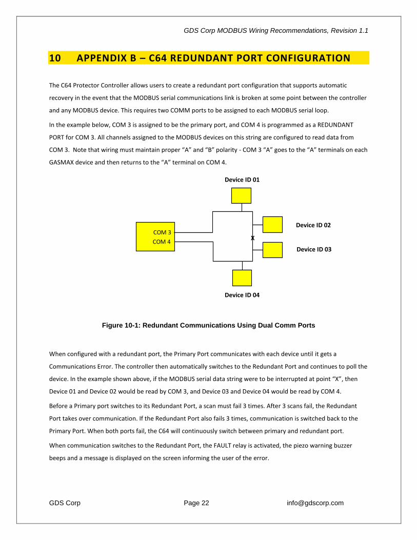
In the example below, COM 3 is assigned to be the primary port, and COM 4 is programmed as a REDUNDANT
PORT for COM 3. All channels assigned to the MODBUS devices on this string are configured to read data from
COM 3. ote that wiring must maintain proper “A” and “B” polarity - COM 3 “A” goes to the “A” terminals on each
GASMAX device and then returns to the “A” terminal on COM 4.
Figure 10-1: Redundant Communications Using Dual Comm Ports
When configured with a redundant port, the Primary Port communicates with each device until it gets a
Communications Error. The controller then automatically switches to the Redundant Port and continues to poll the
device. In the example shown above, if the MODBUS serial data string were to be interrupted at point “X”, then
Device 01 and Device 02 would be read by COM 3, and Device 03 and Device 04 would be read by COM 4.
Before a Primary port switches to its Redundant Port, a scan must fail 3 times. After 3 scans fail, the Redundant
Port takes over communication. If the Redundant Port also fails 3 times, communication is switched back to the
Primary Port. When both ports fail, the C64 will continuously switch between primary and redundant port.
When communication switches to the Redundant Port, the FAULT relay is activated, the piezo warning buzzer
beeps and a message is displayed on the screen informing the user of the error.
COM 3
COM 4
Device ID 01
Device ID 02
Device ID 03
Device ID 04
X
Recommended