http://www.iaeme.com/IJMET/index.asp 1202 [email protected]
International Journal of Mechanical Engineering and Technology (IJMET) Volume 8, Issue 8, August 2017, pp. 1202–1211, Article ID: IJMET_08_08_120
Available online at http://www.iaeme.com/IJMET/issues.asp?JType=IJMET&VType=8&IType=8
ISSN Print: 0976-6340 and ISSN Online: 0976-6359
© IAEME Publication Scopus Indexed
MODAL ANALYSIS OF P-FGM RECTANGULAR
PLATE MADE OF ORTHOTROPIC MATERIALS
UNDER SIMPLY SUPPORTED AND CLAMPED
BOUNDARY CONDITIONS IN BOTH
SYMMETRIC AND ANTISYMMETRIC MODES
OF VIBRATION
S. Karthikeyan
Department of Mathematics, Government Arts College, Salem, Tamilnadu
S. Rama
Department of Mathematics, Mount Carmel College, Bangalore, Karnataka
ABSTRACT
The functionally graded materials have a wide range of applications over medical
science and aerospace engineering. In general the functional gradation has been
exposed only on the two different nature materials. It is necessary to determine the
resonant frequencies of these FGM used in biosensors, actuators and memory devices.
With the help of this resonant frequencies the smart structures capability has been
increased. This paper deals with the determination of the resonant frequencies of
FGM with thickness gradation made by pyroelectric-piezo magnetic materials. The
gradation function has been considered as power-law function of thickness variable.
The initial disturbance has been made by the wave propagation in both symmetric and
antisymmetric modes. For the two types of boundary conditions viz all the sides of the
plate are simply supported and opposite sides are clamped, the non-dimensionalized
frequencies for different exponent and wave numbers have been determined along
with the damping effect. The dispersion curves are drawn. For numerical study, the
FGM plate graded with Barium Titanate (pyroelectric material) and Copper Ferrous
Sulphate (piezo-magnetic material) has been considered.
Keywords: Functionally graded materials, Piezo magnetic, pyroelectric, resonant
frequencies.
Cite this Article: Karthikeyan and S.Rama, Modal Analysis of P-FGM Rectangular
Plate Made of Orthotropic Materials under Simply Supported and Clamped Boundary
Conditions in both Symmetric and Anti-symmetric Modes of Vibration, International
Journal of Mechanical Engineering and Technology 8(8), 2017, pp. 1194–1211.
http://www.iaeme.com/IJMET/issues.asp?JType=IJMET&VType=8&IType=8
S. Karthikeyan and S.Rama
http://www.iaeme.com/IJMET/index.asp 1203 [email protected]
1. INTRODUCTION:
Piezo magnetic materials are mainly used as nonvolatile memory units which have electrically
written data and would be read magnetically. Pyroelectric materials majorly used as bio-
sensors which have more applications in medical field and also in aerospace engineering. The
composite structures of pyroelectric-piezo magnetic materials have wide range of
applications.
Cho and Tingley (2000) analyzed the thermal stress characteristics of FGM introduced in
layered composite materials and optimize the FGM properties to control the thermal stress.
Efrain (2011) derived an accurate formula for natural frequencies of FGM plate and the
isotropic plate made of materials with different poison’s ratio. Nakamura, Wang and Sampath
(2000) used inverse analysis process to determine the displacement at several load magnitudes
and to make best estimates for the unknown parameters. Ramu and Mohanty (2014) carried
out the modal analysis of FGM isotropic plate using FEM and FGM plate program has been
coded in MATLAB software. Weon (2016) investigated the vibration and buckling analysis
of FGM plate using 8 noded shell elements. Liux and Lam (2001) developed a hybrid
numerical method to compute the wave field in an FGM plate for a given material properties
and the gradation has been considered in the thickness direction. Sung, Lomboy and Kim
(2007) investigated the natural frequencies and buckling loads of FGM plates and shells using
4 noded quasi conforming shell elements with the assumptions that the poison ratios of the
materials are constant. Liu, Wang and Chen (2010) analyzed the free vibration of FGM
isotropic rectangular plate by considered the in-plane inhomogeneity of the material
properties. Saritha and Vinayak (2016) performed the thermal analysis and structural analysis
of disc brake by varying the materials like cast Iron, Carbon fiber and used FGM as interface
zone.
In this chapter the functionally graded material with thickness gradation has been
considered and the resonant frequencies for a thin rectangular plate have been determined.
The gradation function has been taken as the power-law function in terms of thickness
variable. Hence the FGM plate is referred as p-FGM plate. The governing and constitutive
equations for the coupled field given in [3]
have been considered and using variational
formulation technique the frequency equations are derived and numerically solved for a set of
boundary conditions viz simply supported boundary conditions and clamped boundary
conditions. The geometry has been exerted to the harmonic wave propagation in different
modes of vibration. The resonant frequencies along with the damping frequencies are
determined and dispersion curves are drawn.
2. P-FGM PLATE THICKNESS GRADATION AND MATERIAL
PROPERTIES:
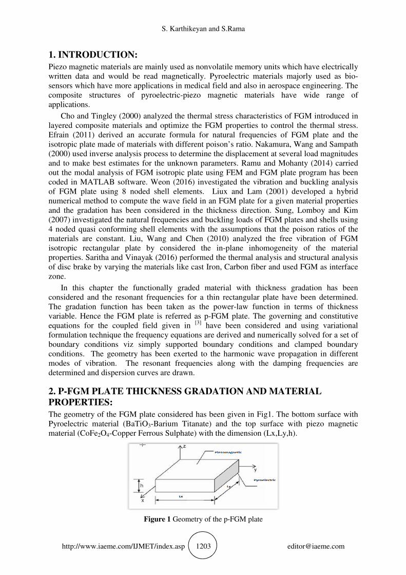
The geometry of the FGM plate considered has been given in Fig1. The bottom surface with
Pyroelectric material (BaTiO3-Barium Titanate) and the top surface with piezo magnetic
material (CoFe2O4-Copper Ferrous Sulphate) with the dimension (Lx,Ly,h).
Figure 1 Geometry of the p-FGM plate

Modal Analysis of P-FGM Rectangular Plate Made of Orthotropic Materials under Simply Supported
and Clamped Boundary Conditions in both Symmetric and Anti-symmetric Modes of Vibration
http://www.iaeme.com/IJMET/index.asp 1204 [email protected]
The initial assumptions made are the surfaces of the plate are traction free, coated with
electrodes and insulated both thermally and magnetically. The gradation of the plate has been
made along thickness direction with the gradation function [10]
( )
p
h
hz
zg
+
= 2
(1)
With p a non-negative real number as exponent. Also the volume fractions obey the above
said power-law such that
Vc(z)=g(z) and Vb(z)+Vc(z)=1 (2)
Where Vc(z) volume fraction of piezo-magnetic material and Vb(z) volume fraction of
pyroelectric material. Clearly Vc(z), Vb(z) ( )hC ,0∂∈ . If p approaches one then the
pyroelectric layer extended and the plate act as a pyroelectric plate whereas p approaches zero
the piezo-magnetic layer extended and the plate act as a piezo-magnetic plate. The material
properties are depending on the thickness variable and volume fractions
( ) bcFGM zgzg γγγ )(1)( −+= (3)
Where cγ -material property of piezo-magnetic material and bγ - material property of
pyroelectric material. By considering the power-law function the material properties of FGM
vary uniformly over the plate in the thickness direction.
3. FREQUENCY EQUATION:
This problem has been considered as multifield problem involving the four fields viz elastic,
electric, thermal and magnetic fields. The constitutive equations and the governing equations
of the plate are considered from [3]
.
3.1 Variational formulation:
In the multifield problem the quantities determine the system are ),,,( ψθφU where
U=(u,v,w)-mechanical displacement, φ -electric potential, θ -change in temperature with
reference to the initial temperature 0θ and ψ -magnetic potential. By variational method
divergence equations are multiplied with the virtual quantities ),,,( δψδθδφδU respectively
and integrated over the domain V. Using the initial approximations in section 1, the integral
weak form of divergence equations
( ) ( )
( )
( ) ( )
( )
0][
][
0
=
⋅∇
+⋅∇
⋅∇
+⋅∇
∫
∫
∫
∫
V
V
V
V
BdV
dVh
DdV
dVUUU
δψ
ηθδθδθ
δφ
ρδσδ
&
&&
(4)
These integral equations are solved by finite element technique. Dividing the model into
finite number of elements and the unknowns are determined at the nodes by Rayleigh-Ritz

S. Karthikeyan and S.Rama
http://www.iaeme.com/IJMET/index.asp 1205 [email protected]
method. Initially the unknowns are approximated as linear combination of the nodal values
and shape functions at each element.
[ ]( ){ } )16(616][ ××× = n
e
n
eeXNX
(5)
Where n-number of nodes per element. Plugging these approximations into the
constitutive equations and has been evaluated at each element. Substituting this
approximation and the transformed constitutive equations into the integral equation (5) yield
the system of homogeneous differential equations at each element referred as element
stiffness equations. The stiffness matrices are given in appendix A.
0}]{[}]{[}]{[ =++ ee
III
ee
II
ee
I XKXKXK &&& (6)
3.2 Approximations and frequency Equation:
Consider the coordinate system (x,y,z) represent the FGM geometrically. The shape
functions are approximated as functions of (x,y,z,t) by separating the in plane variables and
the unknowns vary harmonically in the time domain. Let the system vibrate with an angular
frequency ω which is referred as the resonant frequency of the system. Hence the shape
functions are approximated
[ ] [ ]tie ezhyxfN ω−= )(),( (7)
Where the functions f and h are appropriately chosen to satisfy the mechanical boundary
conditions of the FGM plate. By plugging eqn. (7) in eqn.(6) the element stiffness equation
transformed into frequency equation at each element and assembling the element matrices
yield the global frequency equation
[ ] 0}{][][][ 2 =−− e
IIIIII XKKiK ωω (8)
4. NUMERICAL APPROXIMATIONS AND SOLUTIONS:
For numerical study the material properties for barium titanate and copper ferrous
sulphate materials are considered. At each node there are six degrees of freedom
( )ψθφ ,,,,, wvu . In symmetric mode of vibration, the shape functions for each unknown are
approximated so as to satisfy the mechanical boundary conditions (simply supported and
clamped)
[ ] ( ) ( ) tiju exxzN ω−−= 21
1 qsinqcos
[ ] ( ) ( ) tijv exxinzN ω−−= 21
1 qcosqs
[ ] ( ) ( ) tijw exxinzNNNN ωψθφ −−==== 21
1 qsinqs][][][ (9)
Where j=1:n, xL
lkq
π11 = ,
yL
lkq
π12 = , αcos=l , αsin=m and α is the direction of
harmonic wave propagation and k1 is the wave number. For antisymmetric mode of vibration
sine would be replaced by cosine and cosine would be replaced by sine. Solving the frequency
equation in eqn.(8) for both symmetric and antisymmetric mode of wave propagation the
natural frequencies along with the damping frequencies are obtained and their corresponding
non-dimensionalized values are determined [2]

Modal Analysis of P-FGM Rectangular Plate Made of Orthotropic Materials under Simply Supported
and Clamped Boundary Conditions in both Symmetric and Anti-symmetric Modes of Vibration
http://www.iaeme.com/IJMET/index.asp 1206 [email protected]
( )b
byx
FGMFGMch
LL
1,1
ρωω
=
(10)
Where bρ and c(1,1)b are density and elastic coefficients of pyroelectric material
respectively.
4.1 Simply supported boundary condition:
The material constants are taken for barium titanate and copper ferrous sulphate and the angle
of wave propagation is considered in the direction 30=α . The geometry of the plate is taken
as (0.01, 0.01, 0.03). While solving the frequency equation, the imaginary eigenvalues are
obtained. The real part of the eigenvalues proportional to the natural frequency whereas the
imaginary part corresponds to the damping frequency. The maximum damping frequencies in
symmetric mode of vibration for different exponent and wave numbers are given in figure.2-
figure.5
Figure 2 Exponent=0.125
Figure 3 Exponent=0.5

S. Karthikeyan and S.Rama
http://www.iaeme.com/IJMET/index.asp 1207 [email protected]
Figure 4 Exponent=1
Figure 5 Exponent=4
In the antisymmetric mode of vibration the dispersion curves corresponding to the
damping frequencies are drawn for different exponent (Figure 6)
Figure 6 Dispersion curves for antisymmetric mode of vibration
The results are validated with the literature [4]
for the exponent p=1

Modal Analysis of P-FGM Rectangular Plate Made of Orthotropic Materials under Simply Supported
and Clamped Boundary Conditions in both Symmetric and Anti-symmetric Modes of Vibration
http://www.iaeme.com/IJMET/index.asp 1208 [email protected]
4.2 Clamped boundary conditions:
For symmetric mode the maximum natural frequencies and damping frequencies are
tabulated and are given in table.1
Exponenet=0.125 0.5 1 1.5 2 2.5 3 3.5
Max frequency
0.04377+
i9.145e-11
0.113+
i0.0009476
0.1351+
i0.003426
0.1286+
i0.000122
0.1313+
i0.004796
0.1504+
i0.000267
0.1554+
i0.0001715
Max Damping
4.319e-8+
i0.01433
1.854e-06+
i7.182
1.44e-
07+i0.793
0.04343+
i0.03238
0.006046+
i0.07623
4.307e-8+
i0.2846
5.66e-08+
i0.9703
Exponenet=0.5 0.5 1 1.5 2 2.5 3 3.5
Max frequency
0.04536+
i2.247e-12
0.1206+
i0.001015
0.1441+
i0.003118
0.1367+
i0.0001208
0.1323+
i0.002187
0.1606+
i0.0002475
0.1659+
i0.000157
Max Damping
2.247e-08+
i0.01858
1.055e-6+
i8.161
1.223e-07+
i0.8072
0.04197+
i0.03529
0.0661+
i0.01597
1.254e-07+
i0.313
5.86e-08+
i1.059
exponent=1 0.5 1 1.5 2 2.5 3 3.5
Max frequency
0.04705+
i1.061e-11
0.1285+
i0.001034
0.1534+
i0.002805
0.1451+
i9.187e-05
0.1372+
i6.97e-09
0.1712+
i0.000226
0.1768+
i0.000142
Max Damping
2.564ee-
09+i0.02532
1.143e-06+
i9.224
3.519e-
07+i0.9134
0.03873+
i0.03981
7.6397e-5+
i0.04754
0.01816+
i0.08013
2.214e-07+
i1.198
exponent=4 0.5 1 1.5 2 2.5 3 3.5
Max frequency
0.05149+
i3.419e-11
0.1495+
i0.0009483
0.177+
i0.002032
0.1671+
i9.513e-05
0.1554+
i3.052e-07
0.1981+
i0.0001683
0.2045+
i0.0001039
Max Damping
9.365e-09+
i0.07289
1.67e-08+
i23.2
3.588e-07+
i2.307
0.02526+
i0.8237
0.0023+
i0.08075
3.928e-07+
i6.194
6.124e-08+
i3.026
Table 1 Natural frequencies and damping frequencies for symmetric mode of vibration
For antisymmetric mode of vibration the natural frequencies, damping frequencies and the
damping ratio for different exponent and different wave numbers are tabulated and are given
in Table 2-5
Wave
number
Maximum Imaginary part Maximum Real part
Damping
frequency Real part Damping ratio
Natural
frequency
Damping
frequency Real part
Damping
ratio
Natural
frequency
0.01 0.0005566 0.00848 0.997851831 0.008496251 9.50E-07 0.02924 1 0.02924
0.5 0.0994 1.15E-07 1.15191E-06 0.0994 2.04E-09 0.07486 1 0.07486
1 0.01234 5.05E-07 4.09076E-05 0.01234 7.54E-05 0.08135 1 0.08135003
5
1.5 0.04138 0.0269 0.54503108 0.049354984 3.36E-09 0.1323 1 0.1323
2 7.722 4.03E-06 5.21756E-07 7.722 1.42E-04 0.1126 1 0.11260009
2.5 0.5869 4.23E-08 7.20736E-08 0.5869 4.19E-05 0.1335 1 0.13350000
7
3 0.0595 1.30E-07 2.18992E-06 0.0595 2.37E-04 0.1435 1 0.14350019
5
3.5 0.00201 5.06E-11 2.51642E-08 0.00201 8.27E-05 0.148 1 0.14800002
3
Table 2 Exponent p=0.125

S. Karthikeyan and S.Rama
http://www.iaeme.com/IJMET/index.asp 1209 [email protected]
Wave
number
Maximum imaginary part Maximum real part
Damping
frequency Real part Damping ratio
Natural
frequency
Damping
frequency Real part
Damping
ratio
Natural
frequency
0.01 0.001574 0.01609 0.995249231 0.016166805 1.43E-05 0.03039 1 0.030390003
0.5 0.344 2.45E-08 7.13372E-08 0.344 1.03E-08 0.0792 1 0.0792
1 0.01219 2.95E-09 2.42248E-07 0.01219 1.39E-12 0.08806 1 0.08806
1.5 0.02151 0.04511 0.902634778 0.049975916 1.86E-09 0.1392 1 0.1392
2 8.422 2.03E-06 2.41035E-07 8.422 1.56E-04 0.1201 1 0.120100101
2.5 0.6407 1.36E-08 2.118E-08 0.6407 4.16E-05 0.142 1 0.142000006
3 0.0003749 1.53E-01 0.999996998 0.153000459 3.75E-04 0.153 1 0.153000459
3.5 0.08597 1.15E-01 0.800434869 0.143422038 7.75E-05 1.58E-01 1 0.158000019
Table 3 exponent p=0.5
Wave
number
Maximum imaginary part Maximum real part
Damping
frequency Real part Damping ratio
Natural
frequency
Damping
frequency Real part
Damping
ratio
Natural
frequency
0.01 0.0002498 0.00427 0.998293186 0.004277301 1.25E-05 0.00844 1 0.008440009
0.5 0.07765 1.35E-08 1.73986E-07 0.07765 1.11E-06 0.0837 1 0.0837
1 0.01925 3.81E-03 0.194253836 0.019623808 4.63E-09 0.09266 1 0.09266
1.5 0.0563 3.22E-07 5.71048E-06 0.0563 8.03E-10 0.1463 1 0.1463
2 9.52 1.30E-06 1.3645E-07 9.52 1.65E-04 0.128 1 0.128000106
2.5 0.725 8.38E-08 1.15601E-07 0.725 4.03E-05 0.1508 1 0.150800005
3 1.20E+43 9.08E+44 0.999912429 9.0828E+44 1.20E+43 9.08E+44 0.99991 9.0828E+44
3.5 0.006095 6.38E-02 0.995467731 0.064090475 7.15E-05 1.68E-01 1 0.168300015
Table 4 exponent p=1
Wave
number
Maximum imaginary part Maximum real part
Damping
frequency
Real
part
Damping
ratio
Natural
frequency
Damping
frequency Real part
Damping
ratio
Natural
frequency
0.01 0.01234 4.55E-11 3.68963E-09 0.01234 3.67E-05 0.01636 1 0.016360041
0.5 0.3172 1.57E-07 4.95902E-07 0.3172 3.35E-10 0.09539 1 0.09539
1 0.05091 7.36E-05 0.001445294 0.050910053 1.09E-11 0.1045 1 0.1045
1.5 0.245 4.81E-08 1.96163E-07 0.245 5.10E-10 0.1649 1 0.1649
2 23.95 1.03E-06 4.28392E-08 23.95 1.45E-04 0.1488 1 0.148800071
2.5 1.832 9.19E-02 0.050084444 1.834302074 3.31E-05 0.1733 1 0.173300003
3 1.22E-01 1.17E-05 9.57377E-05 0.122000001 4.57E-03 1.66E-01 0.99962 0.165663046
3.5 0.125 3.60E-11 2.8824E-10 0.125 5.40E-05 1.95E-01 1 0.194600007
Table 5 exponent p=4

Modal Analysis of P-FGM Rectangular Plate Made of Orthotropic Materials under Simply Supported
and Clamped Boundary Conditions in both Symmetric and Anti-symmetric Modes of Vibration
http://www.iaeme.com/IJMET/index.asp 1210 [email protected]
5. CONCLUSIONS:
The natural and damping frequencies of the p-FGM plate made of pyroelectric-piezo
magnetic material have been determined. The two different types of boundary conditions are
considered namely simply supported boundary conditions and clamped boundary conditions.
As exponent approaches 1 the plate behaved as a pyroelectric plate. The following assertions
are obtained from the tabulated results
i. As the wavenumber is very close to zero the damping frequencies are increasing.
ii. The increase of damping frequencies results in a decrease of natural frequency by the
amount (1- 2ζ ). ( −ζ damping ratio)
iii. In case of simply supported boundary conditions as the exponent increase results an
increase in both natural and damping frequencies corresponds to both the mode of
vibrations.
iv. In case of clamped boundary conditions, the symmetric mode of vibration yields the
assertions that the wave numbers increase there is a fluctuation in the damping
frequencies and in antisymmetric mode the maximum real part of the eigenvalues
corresponds to the critical damping and the maximum imaginary part of the
eigenvalues corresponds to the under damping situation for the given dynamical
system. By considering different power laws for the gradation function, the same
mathematical model would be applied to obtain the resonant frequencies of the given
dynamical system.
REFERENCES:
[1] J.R.Cho and J.Tingley orden (2000), Functionally graded material a parametric study on
thermal stress characteristics using the crank-nicolson-galerkin scheme, Computer
methods in applied mechanical and engineering, 188, 17-38.
[2] Elia Efraim (2011), Accurate formula for determination of natural frequencies of FGM
plates basig on frequencies of isotrpic plates”, Engineering procedia, 10,242-247.
[3] S.Karthikeyan and Rama S (2013).Wave Propagation in Magneto Pyroelectric Plates,
Mathematical Sciences International Research Journal, 2(2), 600 - 605.
[4] S.Karthikeyan and Rama S (2016). Free Vibration Analysis of Orthotropic Rectangular
Plate Made of Pyroelectric Material, International Journal of Pure and Applied
Mathematical sciences, 9(2), 273-282.
[5] D.Y.Liu, C.Y.Wangand W.Q.Chen (2010), “ Free vibration of FGM plates with in-plane
material inhomogeneity”, Journal of composite structures, 92(5),1047-1051.
[6] G.R.Liux and Han K.Y.Lam (2001), Material characterization of FGM plate using elastic
waves on an inverse procedure, Journal of composite structures, 35(11), 954-971.
[7] T.Nakamura, T.Wang and S.Sampath (2000), Determination of properties of graded
materials by inverse analysis and instrumented indentation, Acta materialia, 48, 4293-
4306.
[8] I.Ramu and S.C.Mohanty (2014), Modal analysis of FGM plates using finite element
method, Procedia materials science, 6,460-67.
[9] V.Saritha and Vinayak G.Kachare (2016), Finite element analysis of disc brake rotor
using dfferent materials, International journal of mechanical engineering and technology,
7(6),410-416.
[10] Shyang-Ho chui and Yen-Ling chung (2006), Mechanical behavior of functionally graded
material plates under transverse load-Part I:Analysis, International journal of solids and
structures,43(13),3657-3674.

S. Karthikeyan and S.Rama
http://www.iaeme.com/IJMET/index.asp 1211 [email protected]
[11] Sung cheon han, Gilson rescober lomboy and Ki-Du Kim (2007), Mechanical vibration
and buckling analysis of FGM plates and shells using a 4-node quasi conforming shell
element, International journal of structural stability and dynamics, 8(2), 203-229.
[12] Weon-Tae Park (2016), Structural stabilities and dynamics of FGM plates using an
improved 8-ANS finite element, Advances in materials science and engineering, 2016,1-9.
[13] Prince Kumar and Sandeep Nasier, An Analytic and Constructive Approach to Control
Seismic Vibrations in Buildings. International Journal of Civil Engineering and
Technology, 7(5), 2016, pp.103–110.
[14] D. Rajesh, V. Balaji, A. Devaraj and D. Yogaraj, An investigation on Effects of Fatigue
Load on Vibration Characteristics of Woven Fabric Glass/Carbon Hybrid Composite
Beam under Fixed- Free End Condition using Finite Element Method, International
Journal of Mechanical Engineering and Technology 8(7), 2017, pp. 85–91
APPENDIX A
The Stiffness matrices are
[ ] [ ] [ ][ ]dVBcBK U
V
T
UUU ∫=
[ ] [ ] [ ] [ ] [ ]dVBNLLV
U
TTT
UU ∫== λθ θθθ 0
[ ] [ ] [ ][ ]dVBBKV
T
φφφφ ξ∫=
[ ] [ ] [ ] [ ] [ ]dVBpNLLV
TTT
∫== φθφθθφ θ0
[ ] [ ] [ ][ ]dVBkBKV
T
θθθθ ∫=
[ ] [ ] [ ][ ]dVBBKV
T
ψψψψ µ∫=
[ ] [ ] [ ]dVNNM U
V
T
UUU ∫= ρ
[ ] [ ] [ ] [ ]dVBdBKV
TT
UU φφ ∫=
[ ] [ ] [ ]dVNNMV
T
θθθθ ζθ ∫= 0
[ ] [ ] [ ] [ ]dVBqBKV
TT
UU ψψ ∫=
[ ] [ ] [ ] [ ]dVBdBKV
TT
ψφφψ ∫=
[ ] [ ] [ ] [ ][ ] [ ] [ ] [ ]
[ ][ ] [ ] [ ] [ ]
−−
−
−
==
ψψθψφψψ
θθ
φψφθφφφ
ψθφ
KLKK
K
KLKK
KLKK
K
TTT
U
T
U
UUUUU
I 000 [ ] [ ] [ ] [ ]
−==
0000
0000
0000
θψθθφθθ LMLLK TT
U
II
[ ]
==
0000
0000
0000
000UU
III
M
K
[ ] [ ] [ ] [ ] [ ]dVBNLLV
U
TTT
∫== µθ θψθθψ 0
Recommended