MICRO SWITCH™ Sealed Subminiature Basic SwitchesZW Series
Datasheet
2 sensing.honeywell.com
What makes our switches better? The IP67-rated sealed switch is designed to operate in a
variety of demanding applications, reducing the challenge of harsh environments
Wide variety of electrical current carrying capacity allows for a solution in many systems
Switch package designed to accommodate a wide range of temperature requirements
MICRO SWITCH™ ZW Series Sealed Subminiature Basic SwitchesHoneywell’s MICRO SWITCH™ ZW Series is a sealed subminiature snap action switch from the Honeywell family of
Z Series subminiature basic switches. Although small in size, the ZW Series is rated for controlling electrical loads
ranging from logic level/computer-based circuits to power-duty switching (up to 6 amps and up to 250 Vac).
Switches supplied with integral wire leads are sealed to IP67 and are suitable for applications where a switch
assembly would be exposed to liquids or particulate contaminates in the environment from indoor or outdoor use.
A wide variety of stainless steel levers are available and when combined with the subminiature package size,
can adapt the switch for many different applications. The ZW Series is certified to UL, cUL, ENEC, and CQC for
worldwide use.
RIGHT SWITCH FOR THE RIGHT APPLICATIONHARSH ENVIRONMENTS • RELIABILITY • ELECTRICAL RATING
For worldwide use...

3sensing.honeywell.com
Features and Benefits Features and Benefits
SMALL PACKAGE SIZESubminiature package size allows the MICRO SWITCH™ ZW Series switch to fit in many applications where other sensors or switches are too large.
WELL SUITED FOR POWER-DUTY AND LOGIC-LEVEL LOADSSPDT, SPNC, or SPNO switch options are available and designed to meet various circuit requirements. ZW Series can control power-duty switching with silver contacts or logic-level computer-based circuits with gold-plated contacts.
PERFORMS IN WET, DIRTY, AND DUSTY ENVIRONMENTSCatalog listings with integral lead wires are sealed to IP67 for use in environments where exposure to liquid ingress or particulate contaminant could occur.
DESIGN FLEXIBILITYSwitches are built with an integral sealed pin plunger. Various styles of levers expand the versatility of the ZW Series switch in the application. In addition, the ZW Series features a variety of terminations to promote flexibility for the electrical connectivity.
IP67 sealing: pre-wired switches
LAWN TRACTORSReverse alarm for lawn tractorsIndicates seat use on lawn tractors
WATERCRAFTFound on handle-bar controls for personal watercraft (wave runners)
SECURITY SYSTEMS
Acts as an interlock for security system panel
SNOWMOBILESFound on handle-bar controls for snowmobiles
Potential Applications
4 sensing.honeywell.com
ZW Series
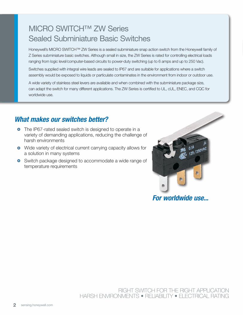
PRODUCT NOMENCLATURE
ZW
Switch TypeCurrentRating
50
Circuitry
3
4
1 SPDT
SPNO 2
NOTES: 1 Not all combinations of model code are available. Please contact your Honeywell provider/representative for assistance.2 Termination style “99” and/or Actuator Type “S” designates a special and therefore requires a special designator letter at the end of the listing3 Lever length is measured as follows: Straight lever - from center line of the pivot to the end of the lever; Roller and simulated roller lever - from the center line of the pivot to the center of the roller diameter. See page 8 for more details.4 Standard wire length is 500 mm [19.68 in] long. Other lengths are available upon request. Lead wire with end stripped 3,0 mm [0.118 in] and pre-tinned. COM: black; NC: gray; NO: blue5 Standard lead wire is UL1007 20 AWG cable. Other lead wire types, such as UL1015, UL1430, UL1061, and AVSS are available upon request.-
E 150 g max.
203 g max.
Operating Force4
(at pin plunger)
F
ZW SeriesSealed
SubminiatureBasicSwitch
50
10
Cable, bottomexit (500 mm)(UL10007 Dia 1.0)4,5
Cable, side exit (Opposite plunger)(500 mm) (UL1007 Dia)4,5
Cable, side exit (Plunger end)(500 mm) (UL1007 Dia)4,5
Long solder 2,8 mm x 0,5 mm[0.11 in x 0.02 in]
PCB, straight
Solder
TerminalType
B20
Pin plunger
C70
90 D
91
92
SPECIAL399
Actuator Type3
(Levers Mounted Internally)
—
15 A
A 1
Construction
D
A special designatoris used to indicate
a non-standard feature, such as a special
actuator, wire color, wire length, connector,
etc. This codeconsists of up to three
alphanumericcharacters.
SpecialDesignator3
15
Short straightlever (17,4 mm) W
IP00Dust tightD
IP67Water tight
Standard straightlever (19,4 mm)
Long straightlever (25,5 mm)
E
F
H
Simulated rollerlever (18,7 mm;R 3,4 mm)
Roller lever(17,2 mm; Ø 4,8 mm) Small simulatedroller lever (18,6 mm; R1,3 mm)
J
S
Long straightlever (55,9 mm)
SPECIAL Lever2
0.1A 125/250 Vac(Gold-platedcontacts)
6A: 125/250 Vac(Silver contacts) F
SPNC 2
ONLY

5sensing.honeywell.com
MICRO SWITCH™ Sealed Subminiature Basic Switches
Table 1. Specifications
Characteristic ZW10 Series (Logic Level) ZW50 Series (Power Duty)
Circuitry SPDT, SPNC, SPNO SPDT, SPNC, SPNO
Operating force 150 g or 203 g @ plunger 150 g or 203 g @ plunger
Termination PCB, solder, prewired PCB, solder, prewired
Sealing IP67 (prewired), IP00 for exposed terminals IP67 (prewired), IP00 for exposed terminals
Actuators (levers 300 series stainless steel)
pin plunger, flat lever, roller lever, sim. roller lever, special levers
pin plunger, flat lever, roller lever, sim. roller lever, special levers
Agency certification UL, cUL, ENEC, CQC, RoHS compliant UL, cUL, ENEC, CQC, RoHS compliant
Operating temperature(Manufacturer rated)
-40 °C to 120 °C [-40 °F to 248 °F] (terminal)-20 °C to 70 °C [-4 °F to 158 °F] (pre-wired)
-40 °C to 120 °C [-40 °F to 248 °F] (terminal)-20 °C to 70 °C [-4 °F to 158 °F] (pre-wired)
Mechanical endurance (cycles) 1,000,000 min. @ 120 cycles/minute max. 1,000,000 min. @ 120 cycles/minute max.
Switch resistance (initial) 50 mΩ max. (terminals); 100 mΩ max (pre-wired) 50 mΩ max. (terminals); 100 mΩ max (pre-wired)
Insulation resistance (initial) 100 MΩ min. (500 Vdc for one minute) 100 MΩ min. (500 Vdc for one minute)
Dielectric strength (initial)(between live parts and ground)
1500 VRMS for one minute <0.5 mA leakage current
1500 VRMS for one minute <0.5 mA leakage current
Plunger seal silicone silicone
Contact material gold-plated silver silver
Housing material case, PBT (polyester); cover, PBT (polyester) case, PBT (polyester); cover, PBT (polyester)
Note: Refer to engineering drawing for additional information.
Table 2. Electrical Ratings
Switch option CQC (Asia-Pacific)Per GB 15092-1
ENEC (Europe)Per IEC 61058-1
UL, cUL (Americas)UL 61058-1, File 12252
ZW10 Series (Gold-plated contacts)
0.1 A, 125/250 Vac10,000 cycles
0.1 A, 250 Vac10,000 cycles
0.1 RA, 125/250 Vac10,000 cycles
ZW50 Series(Silver contacts)
6 A, 125/250 Vac10,000 cycles
6 A, 250 Vac10,000 cycles
5 RA, 125/250 Vac10,000 cycles
Note: The agency “use temperature” for solder or PCB terminals: 0 °C to 120 °C [32 °F to 248 °F]; CQC/ENEC “use temperature” for wire leads: 0 °C to 70 °C [32 °F to 158 °F]. UL/cUL “use temperature” for wire leads: 0 °C to 55 °C [32 °F to 131 °F].

6 sensing.honeywell.com
ZW SeriesO.F. • Operating forceR.F. • Release forceP.T. • PretravelO.T. • OvertravelD.T. • Differential travelO.P. • Operating position
PRODUCT SPECIFICATIONS AND LISTINGSContact your Honeywell rep or distributor for additional listings
Catalog Listing ActuatorCircuitry/ContactMaterial
Elect. Rating Spec.(page 5)
TerminationO.F. max.
N [g]R.F. max.
N [g]
O.P. from mounting hole
mm [in](see page 8)
O.P. from base of terminalmm [in]
(see page 8)
P.T. max. O.T. min. D.T. max.
Pin plunger
ZW10F20AD1 Pin plunger SPDT/ Gold plate 0.1 A PCB 2,00 N [203 g] 0,49 N [50 g] – 11,5 ±0,3
[0.45 ±0.012] 1,2 mm [0.05 in] 0,6 mm [0.02 in] 0,2 mm [0.01 in]
ZW10F90AW1 Pin plunger SPDT/ Gold plate 0.1 A Wire leads, bottom exit
(500 mm) 2,00 N [203 g] 0,49 N [50 g] 8,4 ±0,3 [0.33 ±0.012] – 1,2 mm [0.05 in] 0,6 mm [0.02 in] 0,2 mm [0.01 in]
ZW50F15AD1 Pin plunger SPDT/ Silver 6 A Solder 2,00 N [203 g] 0,49 N [50 g] 8,4 ±0,3
[0.33 ±0.012] – 1,2 mm [0.05 in] 0,6 mm [0.02 in] 0,2 mm [0.01 in]
ZW50F90AW1 Pin plunger SPDT/ Silver 6 A Wire leads, bottom exit
(500 mm) 2,00 N [203 g] 0,49 N [50 g] 8,4 ±0,3 [0.33 ±0.012] – 1,2 mm [0.05 in] 0,6 mm [0.02 in] 0,2 mm [0.01 in]
ZW50F92AW3 Pin plunger SPNO/ Silver 6 A Wire leads, side exit,
plunger side (500 mm) 2,00 N [203 g] 0,49 N [50 g] 8,4 ±0,3 [0.33 ±0.012] – 1,2 mm [0.05 in] 0,6 mm [0.02 in] 0,2 mm [0.01 in]
Std. straight lever
ZW10E15CD1 Standard straight lever, 19,4 mm [0.76 in]
SPDT/ Gold plate 0.1 A Solder 0,54 N [55 g] 0,11 N [11 g] 8,8 ±1,2
[0.35 ±0.047] – 4,8 mm [0.19 in] 1,0 mm [0.04 in] 0,7 mm [0.03 in]
ZW50F90CW3 Standard straight lever, 19,4 mm [0.76 in]
SPNO/ Silver 6 A Wire leads, bottom exit
(500 mm) 0,65 N [66 g] 0,13 N [13 g] 8,8 ±1,2 [0.35 ±0.047] – 4,8 mm [0.19 in] 1,0 mm [0.04 in] 0,7 mm [0.03 in]
ZW50F92CW3 Standard straight lever, 19,4 mm [0.76 in]
SPNO/ Silver 6 A Wire leads, side exit,
plunger side (500 mm) 0,65 N [66] g 0,13 N [13 g] 8,8 ±1,2 [0.35 ±0.047] – 4,8 mm [0.19 in] 1,0 mm [0.04 in] 0,7 mm [0.03 in]
Long straight lever
ZW50F90DW1 Long straight lever, 25,5 mm [1.0 in]
SPDT/ Silver 6 A Wire leads, bottom exit
(500 mm) 0,53 N [54 g] 0,11 N [11 g] 8,8 ±1,6 [0.35 ±0.063] – 6,3 mm [0.25 in] 1,6 mm [0.06 in] 0,9 mm [0.04 in]
ZW50F90JW1 Longer straight lever, 52,9 mm [2.20 in]
SPDT/ Silver 6 A Wire leads, bottom exit
(500 mm) 0,32 N [33 g] 0,07 N [7 g] 8,8 ±3,5 [0.34 ±0.138] – 13,8 mm [0.54 in] 2,9 mm [0.11 in] 3,60 mm [0.14 in]
Sim. roller lever
ZW50F90EW3Sim. roller lever, 18,65 mm [0.73 in]radius: 3,4 mm [0.13 in]
SPNO/ Silver 6 A Wire leads, bottom exit
(500 mm) 0,68 N [69 g] 0,13 N [13 g] 11,7 ±1,15[0.46 ±0.045] – 4,7 mm [0.18 in] 0,9 mm [0.04 in] 0,75 mm [0.03 in]
Sim. roller lever
ZW50F90HW1Small radius, sim. roller lever, 18,6 mm [0.73 in] radius: 1,3 mm [0.05 in]
SPDT/ Silver 6 A Wire leads, bottom exit
(500 mm) 0,67 N [68 g] 0,14 N [14 g] 10,7 ±1,2 [0.42 ±0.047] – 4,6 mm [0.18 in] 1,0 mm [0.04 in] 0,75 mm [0.03 in]
ZW50F91HW1Small radius, sim. roller lever,18,6 mm [0.73 in]radius: 1,3 mm [0.05 in]
SPDT/ Silver 6 A
Wire leads, side exit, opposite plunger
(500 mm)0,67 N [68 g] 0,14 N [14 g] 10,7 ±1,2
[0.42 ±0.047] – 4,6 mm [0.18 in] 1,0 mm [0.04 in] 0,75 mm [0.03 in]
Roller lever
ZW10E70FD1 Roller lever, 17,2 mm [0.68 in]
SPDT/ Gold plate 0.1 A Solder (long terminal) 0,59 N [60 g] 0,12 N [12 g] 14,5 ±1,1
[0.57 ±0.043] – 4,3 mm [0.17 in] 0,9 mm [0.04 in] 0,6 mm [0.02 in]
ZW10E90FW1 Roller lever17,2 mm [0.68 in]
SPDT/ Gold plate 0.1 A Wire leads, bottom exit
(500 mm) 0,59 N [60 g] 0,12 N [12 g] 14,5 ±1,1 [0.57 ±0.043] – 4,3 mm [0.17 in] 0,9 mm [0.04 in] 0,6 mm [0.02 in]
ZW50F90FW1 Roller lever17,2 mm [0.68 in]
SPDT/ Silver 6 A Wire leads, bottom exit
(500 mm) 0,71 N [72 g] 0,15 N [15 g] 14,5 ±1.1 [0.57 ±0.043] – 4,3 mm [0.17 in] 0,9 mm [0.04 in] 0,6 mm [0.02 in]

7sensing.honeywell.com
MICRO SWITCH™ Sealed Subminiature Basic Switches
Catalog Listing ActuatorCircuitry/ContactMaterial
Elect. Rating Spec.(page 5)
TerminationO.F. max.
N [g]R.F. max.
N [g]
O.P. from mounting hole
mm [in](see page 8)
O.P. from base of terminalmm [in]
(see page 8)
P.T. max. O.T. min. D.T. max.
Pin plunger
ZW10F20AD1 Pin plunger SPDT/ Gold plate 0.1 A PCB 2,00 N [203 g] 0,49 N [50 g] – 11,5 ±0,3
[0.45 ±0.012] 1,2 mm [0.05 in] 0,6 mm [0.02 in] 0,2 mm [0.01 in]
ZW10F90AW1 Pin plunger SPDT/ Gold plate 0.1 A Wire leads, bottom exit
(500 mm) 2,00 N [203 g] 0,49 N [50 g] 8,4 ±0,3 [0.33 ±0.012] – 1,2 mm [0.05 in] 0,6 mm [0.02 in] 0,2 mm [0.01 in]
ZW50F15AD1 Pin plunger SPDT/ Silver 6 A Solder 2,00 N [203 g] 0,49 N [50 g] 8,4 ±0,3
[0.33 ±0.012] – 1,2 mm [0.05 in] 0,6 mm [0.02 in] 0,2 mm [0.01 in]
ZW50F90AW1 Pin plunger SPDT/ Silver 6 A Wire leads, bottom exit
(500 mm) 2,00 N [203 g] 0,49 N [50 g] 8,4 ±0,3 [0.33 ±0.012] – 1,2 mm [0.05 in] 0,6 mm [0.02 in] 0,2 mm [0.01 in]
ZW50F92AW3 Pin plunger SPNO/ Silver 6 A Wire leads, side exit,
plunger side (500 mm) 2,00 N [203 g] 0,49 N [50 g] 8,4 ±0,3 [0.33 ±0.012] – 1,2 mm [0.05 in] 0,6 mm [0.02 in] 0,2 mm [0.01 in]
Std. straight lever
ZW10E15CD1 Standard straight lever, 19,4 mm [0.76 in]
SPDT/ Gold plate 0.1 A Solder 0,54 N [55 g] 0,11 N [11 g] 8,8 ±1,2
[0.35 ±0.047] – 4,8 mm [0.19 in] 1,0 mm [0.04 in] 0,7 mm [0.03 in]
ZW50F90CW3 Standard straight lever, 19,4 mm [0.76 in]
SPNO/ Silver 6 A Wire leads, bottom exit
(500 mm) 0,65 N [66 g] 0,13 N [13 g] 8,8 ±1,2 [0.35 ±0.047] – 4,8 mm [0.19 in] 1,0 mm [0.04 in] 0,7 mm [0.03 in]
ZW50F92CW3 Standard straight lever, 19,4 mm [0.76 in]
SPNO/ Silver 6 A Wire leads, side exit,
plunger side (500 mm) 0,65 N [66] g 0,13 N [13 g] 8,8 ±1,2 [0.35 ±0.047] – 4,8 mm [0.19 in] 1,0 mm [0.04 in] 0,7 mm [0.03 in]
Long straight lever
ZW50F90DW1 Long straight lever, 25,5 mm [1.0 in]
SPDT/ Silver 6 A Wire leads, bottom exit
(500 mm) 0,53 N [54 g] 0,11 N [11 g] 8,8 ±1,6 [0.35 ±0.063] – 6,3 mm [0.25 in] 1,6 mm [0.06 in] 0,9 mm [0.04 in]
ZW50F90JW1 Longer straight lever, 52,9 mm [2.20 in]
SPDT/ Silver 6 A Wire leads, bottom exit
(500 mm) 0,32 N [33 g] 0,07 N [7 g] 8,8 ±3,5 [0.34 ±0.138] – 13,8 mm [0.54 in] 2,9 mm [0.11 in] 3,60 mm [0.14 in]
Sim. roller lever
ZW50F90EW3Sim. roller lever, 18,65 mm [0.73 in]radius: 3,4 mm [0.13 in]
SPNO/ Silver 6 A Wire leads, bottom exit
(500 mm) 0,68 N [69 g] 0,13 N [13 g] 11,7 ±1,15[0.46 ±0.045] – 4,7 mm [0.18 in] 0,9 mm [0.04 in] 0,75 mm [0.03 in]
Sim. roller lever
ZW50F90HW1Small radius, sim. roller lever, 18,6 mm [0.73 in] radius: 1,3 mm [0.05 in]
SPDT/ Silver 6 A Wire leads, bottom exit
(500 mm) 0,67 N [68 g] 0,14 N [14 g] 10,7 ±1,2 [0.42 ±0.047] – 4,6 mm [0.18 in] 1,0 mm [0.04 in] 0,75 mm [0.03 in]
ZW50F91HW1Small radius, sim. roller lever,18,6 mm [0.73 in]radius: 1,3 mm [0.05 in]
SPDT/ Silver 6 A
Wire leads, side exit, opposite plunger
(500 mm)0,67 N [68 g] 0,14 N [14 g] 10,7 ±1,2
[0.42 ±0.047] – 4,6 mm [0.18 in] 1,0 mm [0.04 in] 0,75 mm [0.03 in]
Roller lever
ZW10E70FD1 Roller lever, 17,2 mm [0.68 in]
SPDT/ Gold plate 0.1 A Solder (long terminal) 0,59 N [60 g] 0,12 N [12 g] 14,5 ±1,1
[0.57 ±0.043] – 4,3 mm [0.17 in] 0,9 mm [0.04 in] 0,6 mm [0.02 in]
ZW10E90FW1 Roller lever17,2 mm [0.68 in]
SPDT/ Gold plate 0.1 A Wire leads, bottom exit
(500 mm) 0,59 N [60 g] 0,12 N [12 g] 14,5 ±1,1 [0.57 ±0.043] – 4,3 mm [0.17 in] 0,9 mm [0.04 in] 0,6 mm [0.02 in]
ZW50F90FW1 Roller lever17,2 mm [0.68 in]
SPDT/ Silver 6 A Wire leads, bottom exit
(500 mm) 0,71 N [72 g] 0,15 N [15 g] 14,5 ±1.1 [0.57 ±0.043] – 4,3 mm [0.17 in] 0,9 mm [0.04 in] 0,6 mm [0.02 in]
O.F. • Operating forceR.F. • Release forceP.T. • PretravelO.T. • OvertravelD.T. • Differential travelO.P. • Operating position

8 sensing.honeywell.com
ZW SeriesMOUNTING DIMENSIONS
9,50 ± 0,15[0.374 ±0.005]
5,20[0.205]
2,30 ±0,10
Ø 2,30 ± 0,10
2,60 ± 0,10
2,35[0.093]
6,40[0.252]
19,80[0.780]
9,25 [0.364]
MOUNTING DIMENSIONS
6,90[0.272]
2,80[0.110]
2,40[0.094]
7,50[0.295]
7,50[0.295]
4,10[0.161]
0,50 ±0,05[0.020 ±0.002]
2,80[0.110]
0,80[0.031]
0,50 ±0,05[0.020±0.002]
2,80[0.110]
7,50[0.295]
7,50[0.295]
3,20[0.126]
2,40[0.094]
2,40[0.094]
500 min.[19,685]
7,50[0.295]
7,50[0.295]
OP
PT
500 min.[19.685]
500 min.[19.685]
15,40[0.606]
19,25 [0.758] SPDT
15,40 [0.606] SPST
19,25 [0.758] SPDT
15,40 [0.606] SPST
Ø1,80[0.071]
7,50[0.295]
7,50[0.295]
Ø 0,80[0.032]
Ø 1,80[0.071]
Ø1,20[0.047]
TERMINAL TYPES
TYPE 15 - SOLDER (STRAIGHT)
TYPE 92 - CABLE-SIDE EXIT [PLUNGER END]
NC NO COM (GRAY) (BLUE) (BLACK)
B A
COM (BLACK) NO (BLUE) NC (GRAY)
NC (GRAY) NO (BLUE) COM (BLACK)
B DIRECTION A DIRECTION
5,10[0.201]17,20
[0.677]
7,50[0.295]
OP
PT
FP
Ø 2,15[0.085]
17,40[0.685]
PT
OP
19,40[0.764]PT
OP
7,50[0.295]
4,85[0.191]
PT
OP
7,50[0.295]
4,85[0.191]
OP
PT18,65[0.734]
OP
PT
7,50[0.295]
4,85[0.191]
OP
PT
7,50[0.295]
4,85[0.191]
18,60[0.732] PT
7,50[0.295]
4,85[0.191]
55,90[2.201]
OP
R3,40[0.134] Ø4,80
[o.189]R1,30[0.051]
7,45[0.293]
PT
OPFP
4,85[0.191]
7,50[0.295]
7,50[0.295]
4,85[0.191]
6,00[0.236]
6,00[0.236]
6,00[0.236]
6,00[0.236]
6,00[0.236]
6,00[0.236]
6,00[0.236]
ACTUATOR TYPES(ALL ACTUATORS EXCEPT TYPE A AND F ARE 4.0 WIDE)
TYPE A PIN PLUNGER
TYPE BSHORT STRAIGHT LEVER (17.4MM)
TYPE CSTANDARD STRAIGHT LEVER (19.4mm)
TYPE DLONG STRAIGHT LEVER (25.5MM)
TYPE E SIMULATED ROLLER LEVER (18.7MM,R3.4)
TYPE FROLLER LEVER (17.2MM, ROLL Ø4.8)
TYPE HSMALL SIMULATED ROLLER LEVER (18.6MM,R1.3)
TYPE JLONGEST STRAIGHT LEVER (55.9MM)
ABOVE ''OP" FROM MOUNTING HOLE
"OP" FROM TERMINAL(FOR TYPE 20 TERMINAL)
TYPE 90 - CABLE-BOTTOM EXITTYPE 20 - PCB (STRAIGHT) TYPE 70 -LONG SOLDER TERMINALS
TYPE 91 - CABLE-SIDE EXIT [OPPOSITE PLUNGER END]
[0.091 ±0.003]
[0.102 ±0.003]
[0.091 ±0.003]
(35°)
0,60 ±0,05[0.024 ±0.002]
(35°) (35°)
0,50 ±0,05[0.020 ±0.002]
3,0 ±1,0[0.118 ±0.039]
3,0 ±1,0[0.118 ±0.039]
Ø 0,80[0.032]
Ø1,80[0.071]
3,0 ±1,0[0.118 ±0.039]
Ø 0,80[0.032]
Ø1,80[0.071]
Note: unless otherwise noted, a tolerace of ±0,4 mm applies to all dimensions.

004989-2-EN IL50 GLO February 2016Copyright © 2016 Honeywell International Inc. All rights reserved.
Sensing and Productivity Solutions
Honeywell
1985 Douglas Drive North
Golden Valley, MN 55422
honeywell.com
Find out moreHoneywell serves its customers through a worldwide network of sales offices, representatives and distributors. For application assistance, current specifications, pricing or name of the nearest Authorized Distributor, contact your local sales office.
To learn more about Honeywell’s
sensing and switching products,
call +1-815-235-6847 or
1-800-537-6945,
visit sensing.honeywell.com,
or e-mail inquiries to
ADDITIONAL INFORMATIONThe following associated literature is available on the Honeywell web site at sensing.honeywell.com:• Product installation instructions
• Product range guide
• Product nomenclature tree
• Product application-specific information
– Case study: Stamp of approval, ZW Series
– Application note: Sensors and switches for potential HVAC/R applications
– Application note: Sensors and switches in industrial air compressors
– Application note: Sensors and switches in sanitary valves
– Application note: Sensors and switches in valves and flow meters
– Application note: Sensors and switches for potential medical applications
– Application note: Sensors and switches for valve monitors and valve indicators
– Application note: Watertight switches in transportation applications
– Technical bulletin: Applying precision switches
– Technical bulletin: Low energy switch guide
WARNINGPERSONAL INJURYDO NOT USE these products as safety or emergency stop devices or in any other application where failure of the product could result in personal injury.
Failure to comply with these instructions could result in death or serious injury.
WARNINGMISUSE OF DOCUMENTATION• The information presented in this product sheet is for
reference only. Do not use this document as a product installation guide.
• Complete installation, operation, and maintenance information is provided in the instructions supplied with each product.
Failure to comply with these instructions could result in death or serious injury.
WARRANTY/REMEDYHoneywell warrants goods of its manufacture as being free of defective materials and faulty workmanship. Honeywell’s standard product warranty applies unless agreed to otherwise by Honeywell in writing; please refer to your order acknowledgement or consult your local sales office for specific warranty details. If warranted goods are returned to Honeywell during the period of coverage, Honeywell will repair or replace, at its option, without charge those items it finds defective. The foregoing is buyer’s sole remedy and is in lieu of all other warranties, expressed or implied, including those of merchantability and fitness for a particu-lar purpose. In no event shall Honeywell be liable for conse-quential, special, or indirect damages.
While we provide application assistance personally, through our literature and the Honeywell website, it is up to the customer to determine the suitability of the product in the application.
Specifications may change without notice. The information we supply is believed to be accurate and reliable as of this printing. However, we assume no responsibility for its use.
Recommended


![MICRO SWITCH™ Compact Limit Switches, NGC Series · 4 sensing.honeywell.com MICRO SWITC Compact Limit Switches NGC Series Figure 3. Side Rotary A1A/A1B Dimensions Side Exit 12 [0.47]](https://img.dokumen.tips/doc/110x75/612a1d738f4a40428a55bbfd/micro-switcha-compact-limit-switches-ngc-series-4-sensinghoneywellcom-micro.jpg)