MHD Issues and Control in FIRE
C. Kessel
Princeton Plasma Physics Laboratory
Workshop on Active Control of MHD Stability
Austin, TX 11/3-5/2003

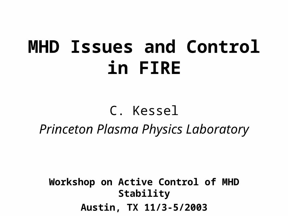
Layout of FIRE Device
TF Coil
CS1
CS2
CS3
PF1,2,3PF4
PF5
VV
R=2.14 ma=0.595 mx=2.0x=0.7Pfus=150 MW
H-modeIp=7.7 MABT=10 TN=1.85li(3)=0.65flat=20 s
AT-modeIp=4.5 MABT=6.5 TN=4.2li(3)=0.40flat=31 s
Cu cladding
Cu stabilizers
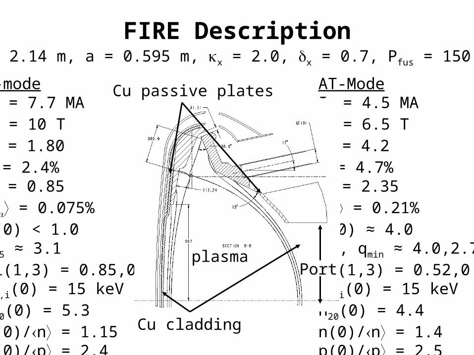
FIRE Description
H-modeIP = 7.7 MABT = 10 TN = 1.80 = 2.4%P = 0.85 = 0.075%q(0) < 1.0q95 ≈ 3.1li(1,3) = 0.85,0.66Te,i(0) = 15 keVn20(0) = 5.3n(0)/n = 1.15p(0)/p = 2.4
R = 2.14 m, a = 0.595 m, x = 2.0, x = 0.7, Pfus = 150 MW
AT-ModeIP = 4.5 MABT = 6.5 TN = 4.2 = 4.7%P = 2.35 = 0.21%q(0) ≈ 4.0q95, qmin ≈ 4.0,2.7li(1,3) = 0.52,0.45Te,i(0) = 15 keVn20(0) = 4.4n(0)/n = 1.4p(0)/p = 2.5
Cu passive plates
Cu cladding
Portplasma

FIRE Auxiliary Systems• ICRF ion/electron heating
– 70-115 MHz
– 2 strap antennas
– 4 ports, 20 MW (10 MW additional reserved)
– BT = 10 T, ion heating minority He3 and 2T for 100 MHz (also obtains a/2 heating)
– BT = 6.5 T, ion heating minority H and 2D for 100 MHz (also obtains a/2 heating)
– BT = 6.5 T electron heating/CD at 70-75 MHz
CD = 0.2 A/W-m2 (AT-mode)
• PF coils, fast Z and R control coils, RWM feedback coils, error field correction coils
• LH electron heating/CD– 5 GHz– n|| ≈ 2, n|| ≈ 0.3– 2 ports, 30 MW CD = 0.16 A/W-m2 (BT = 6.5 T)
and 0.25 A/W-m2 (BT = 8.5 T)**
• EC electron heating/CD– 170 GHz– in LH ports, top and bottom– 20+ MW? CD = 0.043 A/W-m2
• Pellet/gas injection and divertor pumping– HFS, 125 m/s– LFS, vertical at higher speeds
– 16 cryo pumps (top&bottom)
**30-50% increase with 2D FP
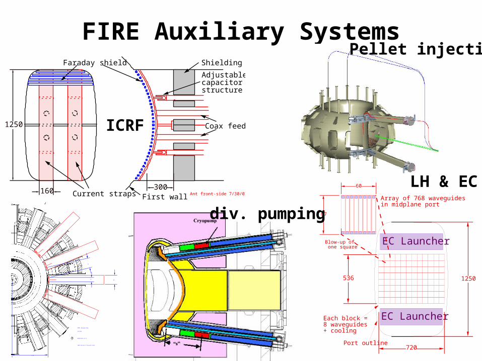
FIRE Auxiliary Systems
1250
160 300Current straps
Faraday shield
Coax feeds
First wall Ant front-side 7/30/03
Adjustablecapacitorstructure
Shielding
.32
.71
2.56
.65
FIRE Antenna Plan
4/24/01
Dimensions in m
1999 version of Vacuum vessel Port outline
Each block =8 waveguides+ cooling
1250
720
Array of 768 waveguides in midplane port
536
EC Launcher
EC Launcher
Blow-up of one square
60
67
ICRF
div. pumping
Pellet injection
LH & EC
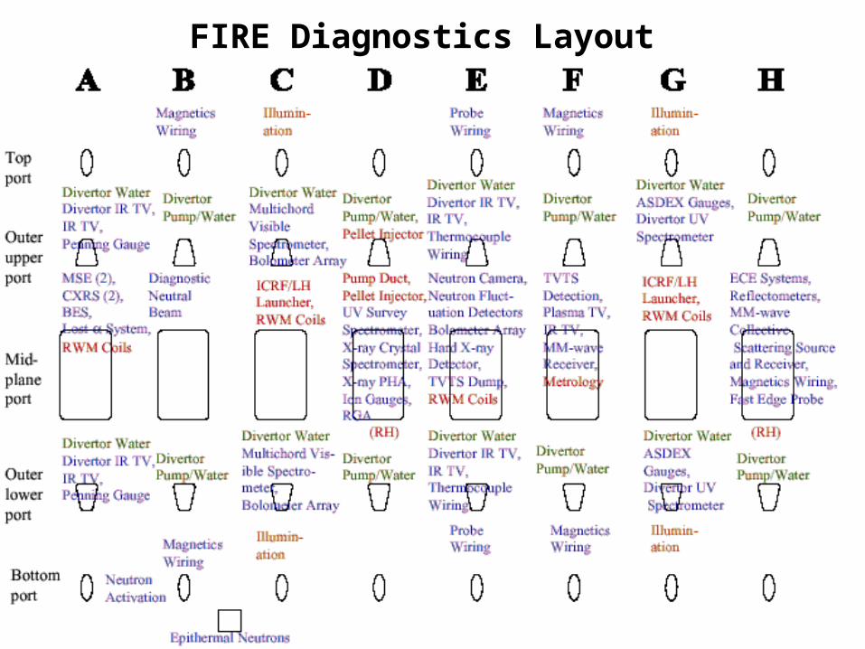
FIRE Diagnostics Layout
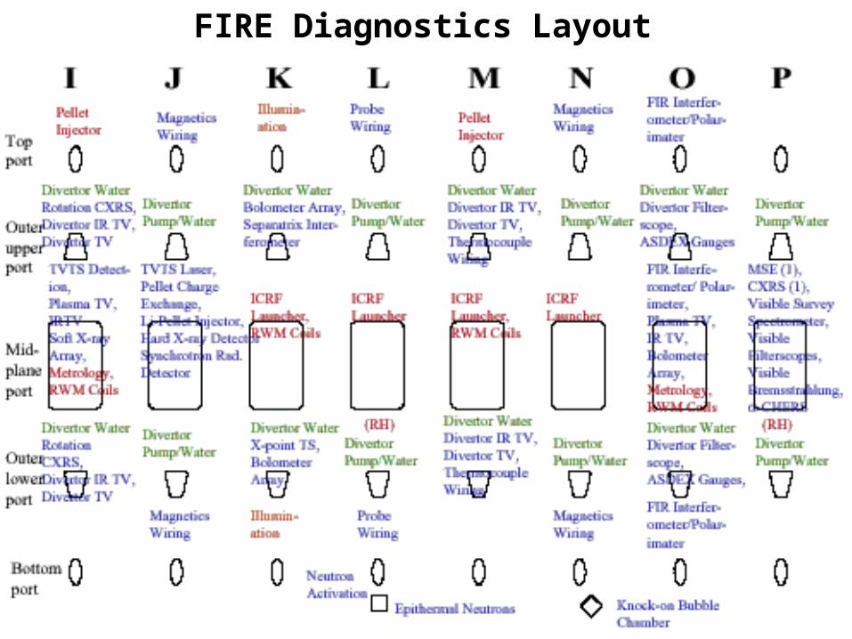
FIRE Diagnostics Layout
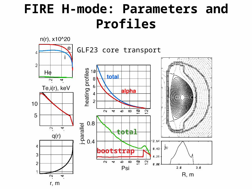
FIRE H-mode: Parameters and Profiles
total
bootstrap
GLF23 core transport
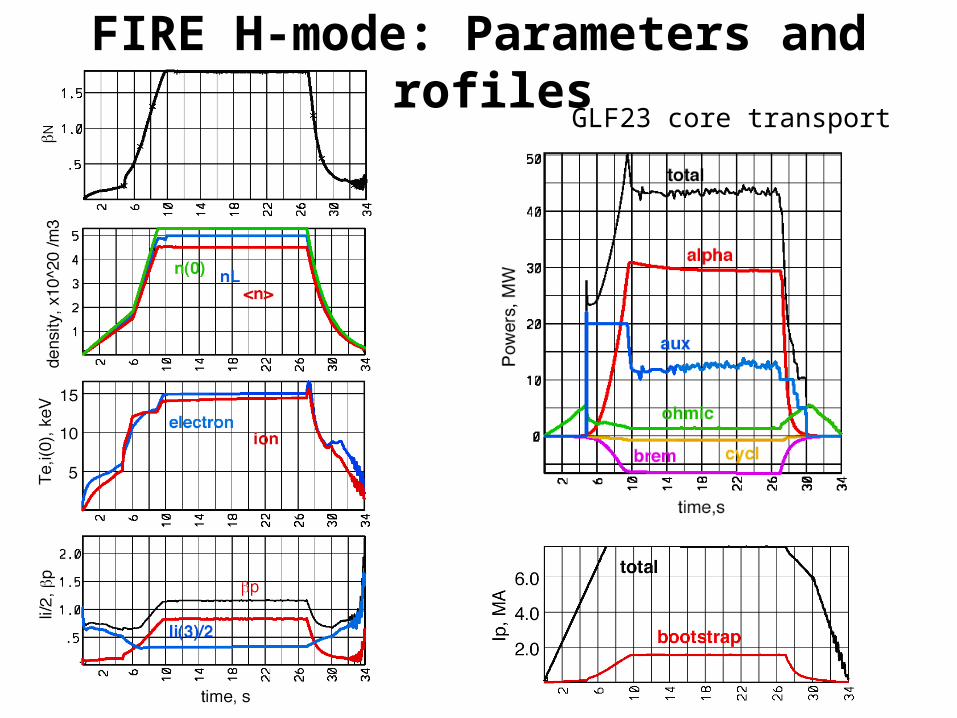
FIRE H-mode: Parameters and Profiles
GLF23 core transport
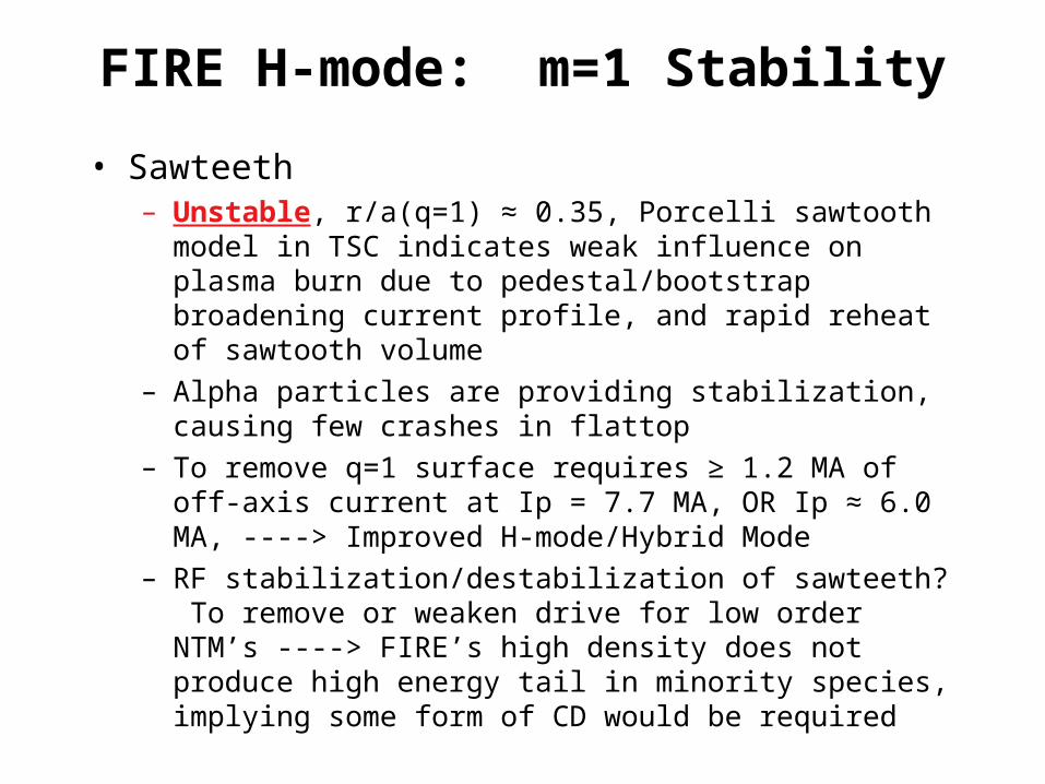
FIRE H-mode: m=1 Stability
• Sawteeth– Unstable, r/a(q=1) ≈ 0.35, Porcelli sawtooth model in TSC
indicates weak influence on plasma burn due to pedestal/bootstrap broadening current profile, and rapid reheat of sawtooth volume
– Alpha particles are providing stabilization, causing few crashes in flattop
– To remove q=1 surface requires ≥ 1.2 MA of off-axis current at Ip = 7.7 MA, OR Ip ≈ 6.0 MA, ----> Improved H-mode/Hybrid Mode
– RF stabilization/destabilization of sawteeth? To remove or weaken drive for low order NTM’s ----> FIRE’s high density does not produce high energy tail in minority species, implying some form of CD would be required

FIRE H-mode: m=1 Stability no sawtooth
FIRE H-mode: Neo-Classical Tearing Modes
• Neo-Classical Tearing Modes– Unstable or Stable?
– Flattop time (20 s) is 2 current diffusion times, j() and p() are relaxed
– Sawteeth and ELM’s as drivers are expected to be present
– Operating points are at low N and P, can they be lowered further and still provide burning plasmas ----> yes, lowering Q
– EC methods are difficult in FIRE H-mode due to high field and high density (280 GHz to access Ro)
– LH method of bulk current profile modification can probably work, but will involve significant power, affecting achievable Q ----> is there another LH method such as pulsing that needs less current?

FIRE H-mode: Neo-Classical Tearing Modes TSC-LSC simulation
POPCON shows access to lower N operating points
(3,2) surface
P(LH)=12.5 MW
I(LH) = 0.65 MA
n/nGr = 0.4
PEST3 analysis needed
FIRE H-mode: Ideal MHD Stability
• n=1 external kink and n=∞ ballooning modes
– Stable without a wall/feedback
– Under various conditions; sawtooth flattened/not flattened current profiles, strong/weak pedestals, etc. N ≤ 3
– EXCEPT in pedestal region, ballooning unstable depending on pedestal width and magnitude
• Intermediate n peeling/ballooning modes
– Unstable, primary candidate for ELM’s
– Type I ELM’s are divertor lifetime limiting, must access Type II, III, or other lower energy/higher frequency regimes
• Ploss/PLH ≈ 1.0-1.6 in flattop, not > 2 like many present experiments
– FIRE has high triangularity (x = 0.7) in Double Null and high density (n/nGr < 0.8)
– What active methods should be considered?
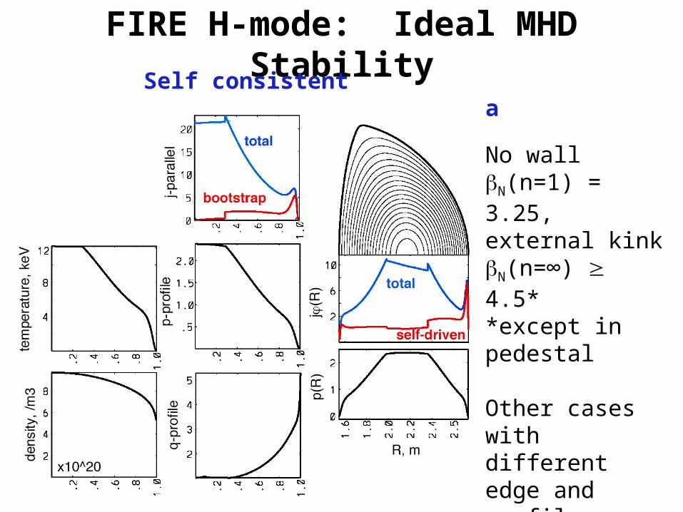
FIRE H-mode: Ideal MHD StabilitySelf consistent bootstrap/ohmic equilibria
No wallN(n=1) = 3.25, external kinkN(n=∞) 4.5**except in pedestal
Other cases with different edge and profile conditions yield various results ----->N ≤ 3
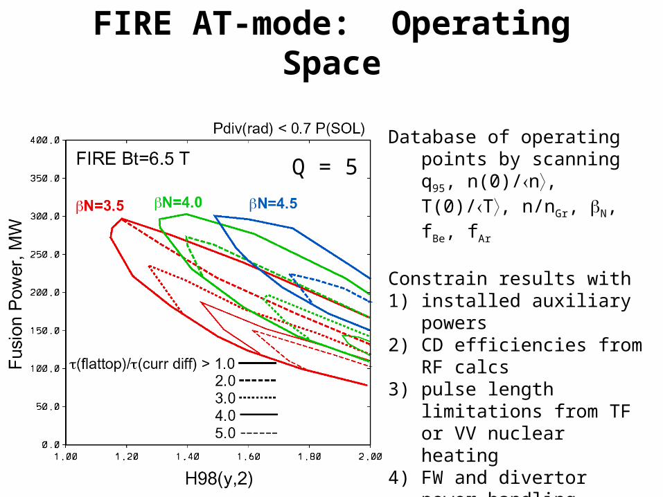
FIRE AT-mode: Operating Space
Database of operating points by scanning q95, n(0)/n, T(0)/T, n/nGr, N, fBe, fAr
Constrain results with1) installed auxiliary powers2) CD efficiencies from RF calcs 3) pulse length limitations from
TF or VV nuclear heating4) FW and divertor power
handling limitations
identify operating points to pursue with more detailed analysis
Q = 5

FIRE AT-mode: Parameters and Profiles
Ip = 4.5 MA, BT = 6.5 T

FIRE AT-mode: Parameters and Profiles
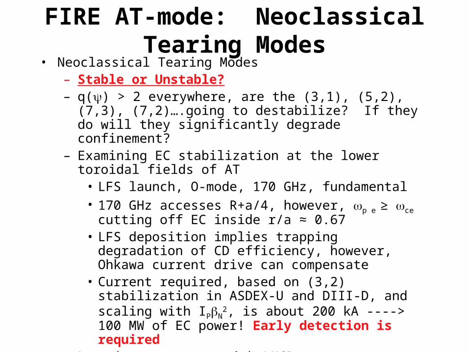
FIRE AT-mode: Neoclassical Tearing Modes
• Neoclassical Tearing Modes– Stable or Unstable?– q() > 2 everywhere, are the (3,1), (5,2), (7,3), (7,2)….going to
destabilize? If they do will they significantly degrade confinement?
– Examining EC stabilization at the lower toroidal fields of AT• LFS launch, O-mode, 170 GHz, fundamental• 170 GHz accesses R+a/4, however, p e ≥ ce cutting off EC
inside r/a ≈ 0.67• LFS deposition implies trapping degradation of CD efficiency,
however, Ohkawa current drive can compensate• Current required, based on (3,2) stabilization in ASDEX-U
and DIII-D, and scaling with IPN2, is about 200 kA ----> 100
MW of EC power! Early detection is required– Launch two spectra with LHCD system, to get regular bulk CD
(that defines qmin) and another contribution in the vicinity of rational surfaces outside qmin to modify current profile and resist NTM’s ----> this requires splitting available power
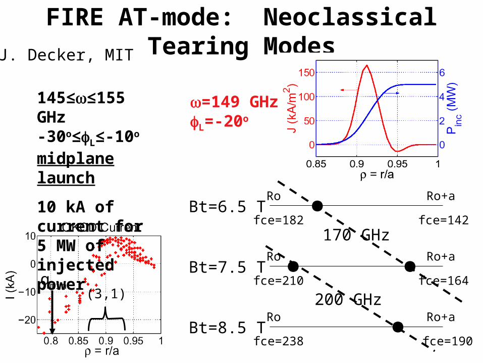
FIRE AT-mode: Neoclassical Tearing Modes
145≤≤155 GHz-30o≤L≤-10o
midplane launch
10 kA of current for 5 MW of injected power
=149 GHzL=-20o
Bt=6.5 T
Bt=7.5 T
Bt=8.5 T
Ro
Ro
Ro
Ro+a
Ro+a
Ro+a
fce=182 fce=142
fce=210 fce=164
fce=190fce=238
170 GHz
200 GHz
J. Decker, MIT
qmin(3,1)
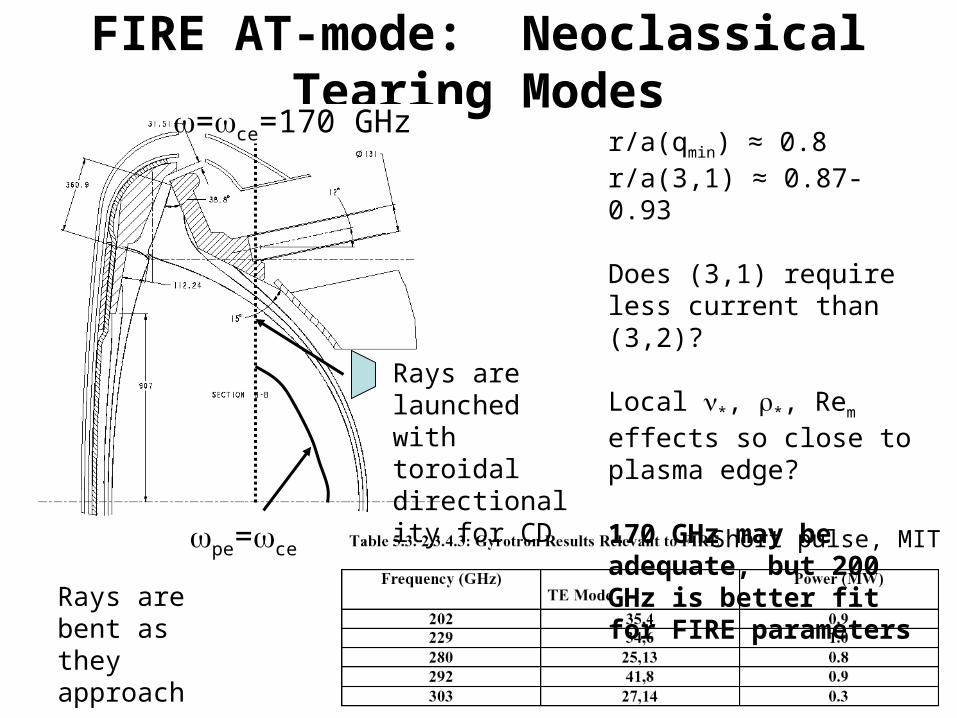
FIRE AT-mode: Neoclassical Tearing Modes
=ce=170 GHz
pe=ce
Rays are launched with toroidal directionality for CD
Rays are bent as they approach =pe
Short pulse, MIT
r/a(qmin) ≈ 0.8r/a(3,1) ≈ 0.87-0.93
Does (3,1) require less current than (3,2)?
Local *, *, Rem effects so close to plasma edge?
170 GHz may be adequate, but 200 GHz is better fit for FIRE parameters

FIRE AT-mode: Ideal MHD Stability
• n= 1, 2, and 3…external kink and n = ∞ ballooning modes– n = 1 stable without a wall/feedback for N < 2.5-2.8– n = 2 and 3 have higher limits without a wall/feedback– Ballooning stable up to N < 6.0, EXCEPT in pedestal region of H-mode
edge plasmas, ballooning instability associated with ELM’s– Specifics depend on po/p, H-mode or L-mode edge, pedestal
characteristics, level of LH versus bootstrap current, and Ip (q*)
– FIRE’s RWM stabilization with feedback coils located in ports very close to the plasma, VALEN analysis indicates 80-90% of ideal with wall limit for n=1, actual wall location is 1.25a
– n = 1 stable with wall/feedback to N’s around 5.0-6.0 depending on edge conditions, wall location, etc.
– n = 2 and 3 appear to have lower N limits in presence of wall, possibly blocking access to n = 1 limits ----> how are these modes manifesting themselves in the plasma when they are predicted to be linear ideal unstable? Are they becoming RWM’s or NTM’s
• Intermediate n peeling/ballooning modes– Unstable under H-mode edge conditions
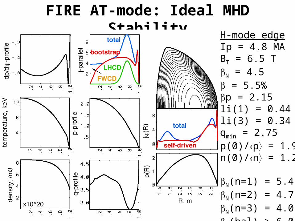
FIRE AT-mode: Ideal MHD StabilityH-mode edgeIp = 4.8 MABT = 6.5 TN = 4.5 = 5.5%p = 2.15li(1) = 0.44li(3) = 0.34qmin = 2.75p(0)/p = 1.9n(0)/n = 1.2
N(n=1) = 5.4N(n=2) = 4.7N(n=3) = 4.0N(bal) > 6.0*

FIRE AT-mode: Ideal MHD StabilityL-mode edgeIp = 4.5 MABT = 6.5 TN = 4.5 = 5.4%p = 2.33li(1) = 0.54li(3) = 0.41qmin = 2.61p(0)/p = 2.18n(0)/n = 1.39
N(n=1) = 6.2N(n=2) = 5.2N(n=3) = 5.0N(bal) > 6.0*

AT Equilibrium from TSC-LSC Dynamic Simulations
TSC-LSC equilibriumIp=4.5 MABt=6.5 Tq(0)=3.5, qmin=2.8N=4.2, =4.9%, p=2.3li(1)=0.55, li(3)=0.42p(0)/p=2.45 n(0)/n=1.4
Stable n=Stable n=1,2,3 with no wall
√V/Vo
L-mode edge
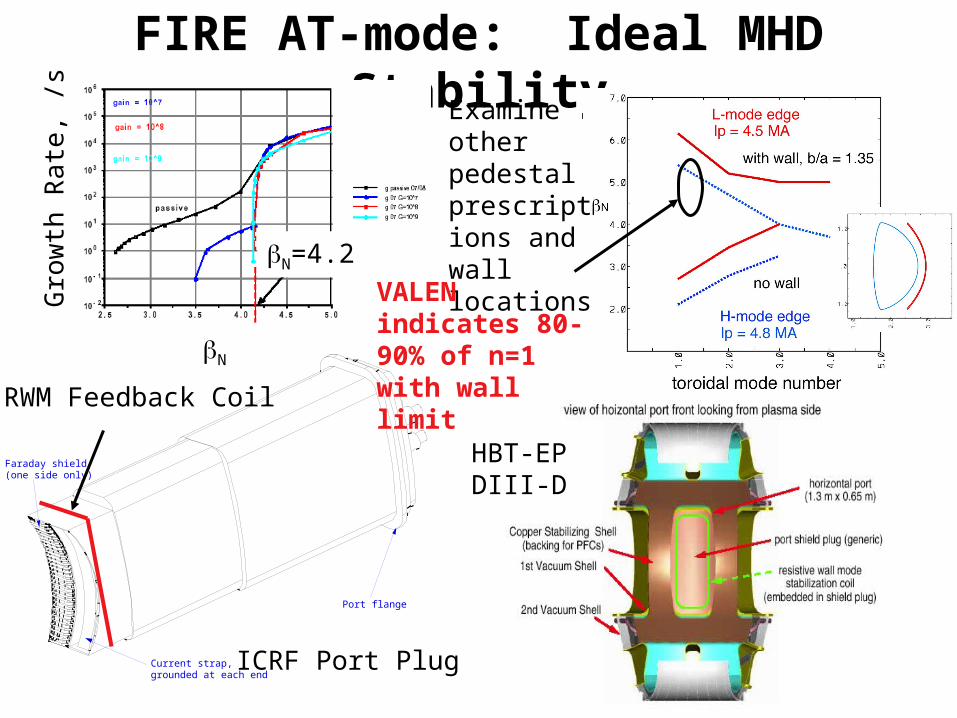
FIRE AT-mode: Ideal MHD Stability
Current strap, grounded at each end
Faraday shield(one side only)
Port flange
ICRF Port Plug
RWM Feedback Coil
Gro
wth
Rat
e, /s
N
N=4.2
Examine other pedestal prescriptions and wall locations
VALEN indicates 80-90% of n=1 with wall limit
HBT-EPDIII-D
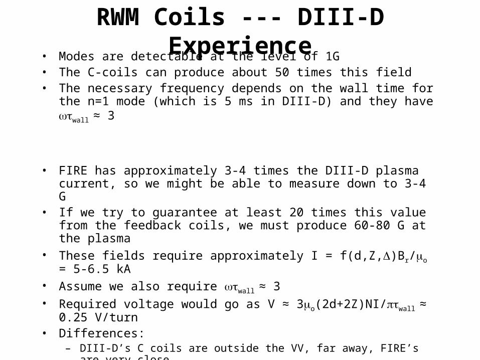
RWM Coils --- DIII-D Experience• Modes are detectable at the level of 1G• The C-coils can produce about 50 times this field• The necessary frequency depends on the wall time for the n=1 mode (which is
5 ms in DIII-D) and they have wall ≈ 3
• FIRE has approximately 3-4 times the DIII-D plasma current, so we might be able to measure down to 3-4 G
• If we try to guarantee at least 20 times this value from the feedback coils, we must produce 60-80 G at the plasma
• These fields require approximately I = f(d,Z,)Br/o = 5-6.5 kA• Assume we also require wall ≈ 3• Required voltage would go as V ≈ 3o(2d+2Z)NI/wall ≈ 0.25 V/turn• Differences:
– DIII-D’s C coils are outside the VV, far away, FIRE’s are very close– DIII-D has 6 coils, FIRE has 8 with smaller toroidal extent– DIII-D VV is made of Inconel, FIRE has Cu cladding on SS (wall)– FIRE has large ports providing smaller wall area (VALEN model is accurate)

FIRE H-mode and AT-Mode: Other• Alfven eigenmodes and energetic particle modes
– Snowmass assessment indicated stable for H-mode, and AT-mode not analyzed
• TF field ripple is low: H-mode losses 0.3%, AT-mode at 4.5 MA loses 7-8%, Fe shims are desired in between VV and TF
• Error fields from coil misalignments, etc. ----> install Cu window coils outside TF coil, stationary to slow response
• Disruptions ----> – Pellet and gas injectors will be all over the device, resulting radiative heat
load is high– Up-down symmetry implies plasma is at or near the neutral point, not
clear if this can be used to mitigate or avoid VDE’s (JT-60U, C-Mod)– Use of RWM feedback coils for ultra fast vertical control?
• Vertical position control (n=0)– Cu passive stabilizers providing instability growth time of ≈ 30 ms,
vertical feedback coils located outside inner VV on outboard side
• Fast radial position control, antenna coupling, provided by same coils as vertical control
• Shape control provided by PF coils

FIRE H-mode and AT-mode: Other
TF Coil
CS1
CS2
CS3
PF1,2,3PF4
PF5
Error correction coils
Fast vertical and radial position control coil RWM feedback coil
Fe shims

FIRE H-mode and AT-mode: OtherdIP/dt(max) = 1-3 MA/msquench = 0.1 msIhalo/IP TPF = 0.5-0.75
HFS launch with 125 m/s, accesses core according to latest Parks modeling, and much higher speeds with LFS and vertical launch
Questions: Plasma Rotation
• Externally driven plasma rotation– NBI for FIRE H-mode is prohibitive, > 1 MeV beams to access
core– Off-axis NBI in FIRE-AT with conventional beams might be
possible?– “Pinwheel” port configuration, if necessary for NBI, OK’d by
engineers for FIRE
– Can fusion reactor plasmas be rotated externally?– What MHD results are critically dependent on external rotation,
what are implications in absense of strong external rotation?– Plasma self-rotation (C-Mod) is sufficient for transport, resistive
stability, ideal/RWM stability? Sheared rotation versus bulk rotation
– Error fields will still be present at some magnitude, causing a plasma response that amplifies them, affecting self-rotation

Questions: NTM control by jbulk() or jlocal() in BP limit
• NTM stabilization techniques– Does early detection remove the island or reduce it to a lower wsat
– Bulk current profile control to make ’ more negative at rational surface with LHCD or ECCD
• Positioning requirements less stringent?
• Needs larger driven current
– Local current drive to replace bootstrap current with ECCD• From DIII-D experience, searching and dwelling, and tracking after
suppression
• Smaller total current requirement, however, scaling with Ip*N2 to
burning devices can lead to high currents
– Do we need to do this at all??• Stationary plasmas with NTM (saturated) at sufficiently high N (T.
Luce at APS2003)
• Strategy might be to control profiles to avoid excessive confinement loss in presence of NTM, rather than trying to stabilize the NTM

Questions: RWM’s and Error Fields
• When error fields are present, we are feeding back on a mode that is different than a pure kink mode (in absense of error field), which is what we are doing analysis on?
• The higher n kink modes are linearly ideal unstable at a lower N than n=1, with a wall– Are they becoming RWM’s
– Are they becoming tearing modes, as the ideal MHD limit is approached, ultimately becoming NTM’s
– Are they edge localized modes, peeling modes
– n=2 and 3 limits may be closer to n=1 limit at higher pressure peaking, and depend on wall location
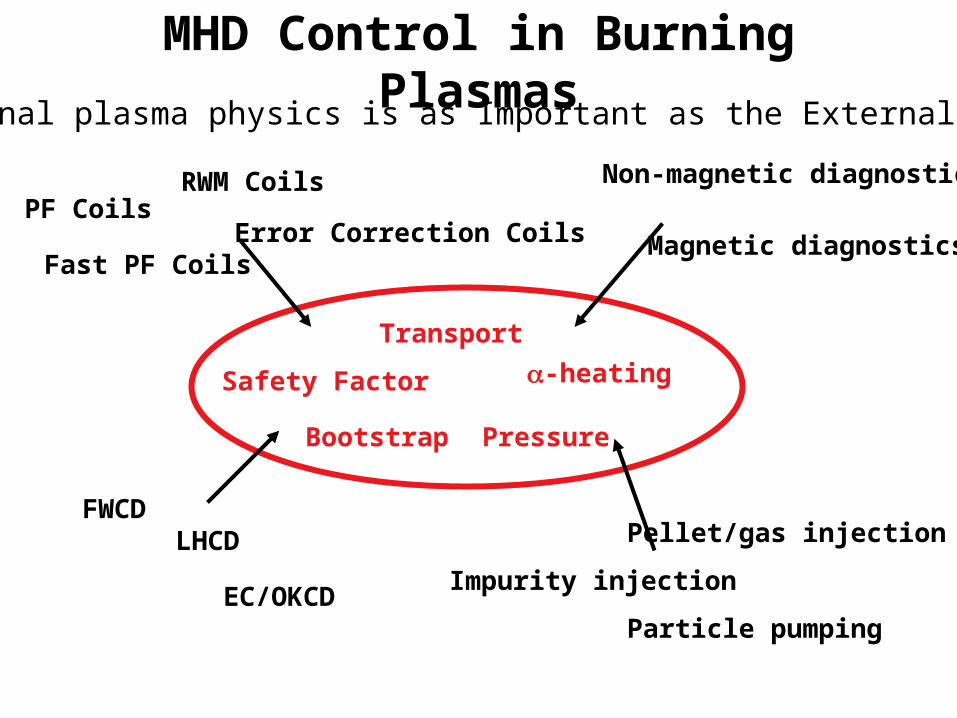
MHD Control in Burning Plasmas
PF Coils
Fast PF Coils
RWM Coils
Error Correction Coils
FWCDLHCD
Bootstrap
EC/OKCD
Magnetic diagnostics
Non-magnetic diagnostics
Pellet/gas injection
Particle pumping
Impurity injection
Safety Factor
Transport
-heating
Pressure
Internal plasma physics is as Important as the External Tools
Recommended