SCCER-FURIES Annual ConferenceDecember 2, 2016
Thomas Guillod, Johann W. KolarPower Electronic Systems Laboratory, ETH Zurich, Switzerland
Medium-Frequency Transformersfor Smart Grid Applications: Challenges and Opportunities

2/19
Transformers: Principle
► Construction ► One magnetic core ► Two windings (at least)
► Functionalities ► Voltage conversion ► Galvanic insulation
► Usages ► Isolation (converters, drives, etc.) ► Interfacing of different voltages
► Key component of power grids ► Efficiency ► Weight / volume ► Functionalities
▼ Transformer / 1 MVA / 50 Hz
[ABB]
▼ Transformer Schematic
core
windings

3/19
Transformers: Performances
► Low-Frequency Transformer (LFT)► Advantages ► Relatively inexpensive ► Highly robust / reliable ► Highly efficient (98.0% to 99.5%)
► Weaknesses ► Voltage drop under load ► Not directly controllable ► Large volume / heavy ► Fire hazards ► Only AC (no DC)
► Compatible with future applications?
[africancrisis.org]
▼ Welding Transformer

4/19
Transformers: Limitations
► Similar geometry and materials► Similar performances
► Where are the limitations?
►
► Physical limitations
: Flux density
: Rated Power: Fill factor: Current density
: Frequency
▼ Modern Transformer▼ Transformer / Stanley / 1885
[ABB][Edison Tech Center]
130 years
▼ Area Product

5/19
Transformers: Scaling Laws
► Scaling laws
►
►
► Medium-Frequency Transformer (MFT)► Increased power density► Increased efficiency
▼ Scaling LawsEf
ficie
ncy
[%]
Power Density [kW/dm3]
50 500 5k 50k 500k
0
50
100
Frequency [Hz]
Volu
me
[%]
f f fff
▼ Performance Pareto Fronts▼ Traction MFT
[STS Trafo]
6/19
Transformers: Comparison LFT/MFT
► Single phase 25 kW MV/LV transformer► Comparison is “not fair” (for both sides)
[ETHZ PES]
▼ 50 kHz
[HPS MILLENNIUM]
25 kVA5 kV / 240 V
60 Hz
98.3%230 dm3
160 kg
31 kVA4 kV / 400 V50 kHz
99.5%2.8 dm3
5.1 kg
vs.
▼ 60 Hz
≈≈
x 800
+ 1.2%÷ 80÷ 30

7/19
Challenges: #1 Power Electronic
► No MF grids or loads► AC-DC / DC-DC converters
► Advantages ► Voltage / current control ► DC / AC buses
► Weaknesses ► Complexity / robustness ► Costs / efficiency
► MFT requires converters
▼ Typical MV/MF Energy Conversion
▼ 160 kW / 20 kHz / DC-DC
[ETHZ P
ES]
AC
DC
DC
AC
Insulation Stage
▼ Typical Transformer Excitation
Volt
age
[a.u
.]
Time [us]
Curr
ent
[a.u
.]0 10 5020 30 40

8/19
Challenges: #2 Core Losses
► Critical at MF ► Hysteresis ► Eddy currents ► Non-sinusoidal flux
► Other materials ► Silicon steel [0.1-1 kHz] ► Nanocrystaline [1-20 kHz] ► Ferrite [10-300 kHz]
► Lower saturation flux► Loss computation is difficult
► Optimal frequency / flux density
▼ Ferrite / Nanocrystaline Cores
▼ Non-ideal Flux Distribution
[ETHZ PES]
[EPCOS / VAC]

9/19
Challenges: #3 Winding Losses
► Critical at MF ► Skin effect ► Proximity effect
► Other configurations ► Foil conductors ► HF litz wires
► Lower fill factor► Loss computation is difficult
► Optimal frequency / wire
▼ Magnetic Stray Field
▼ Skin / Proximity Effects
[ETHZ PES]
[ETHZ PES]
▼ HF Litz Wire
[Pack]
▼ Litz Wire Current Distribution
Curr
ent
[a.u
.]
[ETH
Z PE
S]
Time [us]0 10 5020 30 40

10/19
Challenges: #4 Parasitics
► Magnetic parasitics ► Leakage flux ► Magnetizing flux
► Electric parasitics ► Winding capacitances ► Earth capacitances
► Problems ► Non-ideal current waveforms ► Oscillations ► EMI problems
► Parasitics are more important at MF and HF
▼ Transformer Equivalent Circuit
▼ Resonances
CGND
CMV,LV
n:1L
m
Lσ
CMV
CLV
CGND
Rm
Rσ
Frequency [Hz]
Impe
danc
e [a
.u.]
100 1k 10k 100k 10M 100M
0 5 10 15 20Time [us]
Curr
ent
[a.u
.]
1M
[ETH
Z PE
S][E
THZ
PES]

11/19
Challenges: #5 Heat Management
► Increased loss density► Critical for the cooling
► Dry-type ► Convective cooling ► Water cooling ► Phase change cooling
► Oil-type
► Efficient cooling is required
▼ Phase Change Cooling
▼ Forced Air Cooling
▼ Water Cooling
▼ Forced Oil Cooling
[ETHZ PES]
[ETHZ PES]
[ETHZ PES][ABB]
12/19
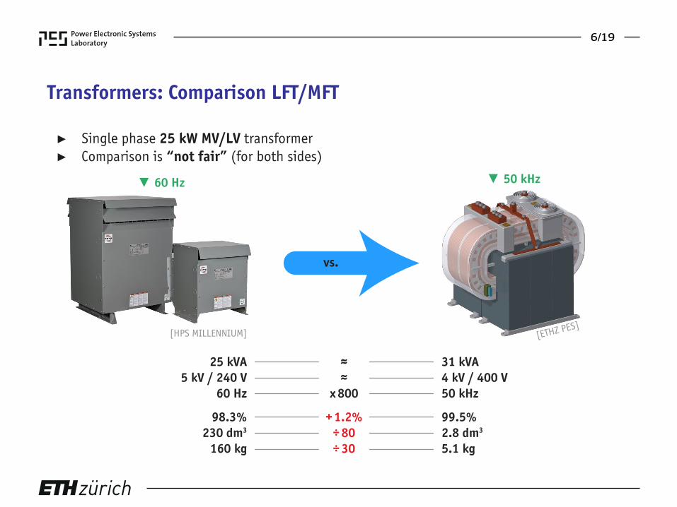
Challenges: #6 Insulation Coordination
► MV voltages (1-36 kV)► DC / AC / MF voltages (DC-1 MHz)► High switching speeds (5-80 kV/us)
► Potential problems ► Dielectric losses ► Thermal breakdown ► Partial discharges ► Space charge migration ► Cracks
/
delamination
/
voids
► Insulation type ► Air insulation ► Dry-type insulation ► Oil insulation
► Reliability of MFT insulation is unclear
▼ Oil Insulation
▼ Dry-type Insulation
[Bombardier]
[Siemens]

13/19
SCCER-FURIES: Insulation
► Insulation of MFTs ► Material testing ► Insulation concept
► MV/MF insulation test bench ► 30 kV AC or DC ► 2.5 kV PWM ► Breakdown /
partial discharges ► Dielectric spectroscopy
► Selection of materials and concepts
▼ Measurement Setup
▼ Waveform
20
22
0 50 100Time [us]
Volt
age
[kV]
21
▼ Epoxy Specimen▼ Epoxy Specimen ▼ Inverter
[ETHZ PES/HVL]
[ETH
Z PE
S/H
VL]
[ETHZ PES][ETHZ HVL]
14/19
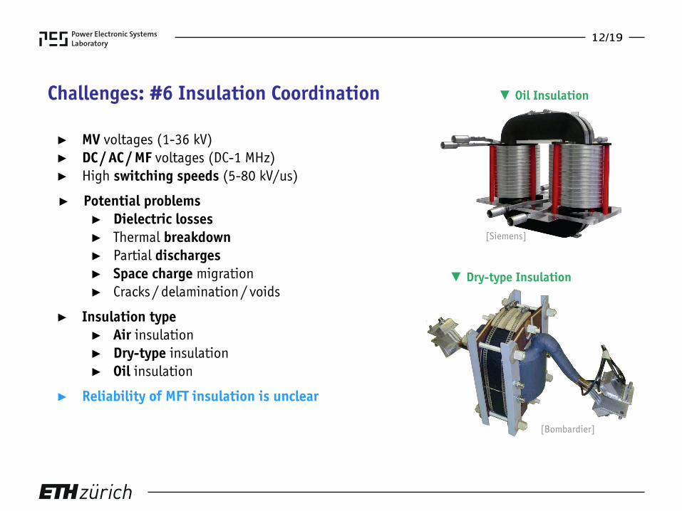
SCCER-FURIES: Transformer
► Virtual transformer prototyping ► Copper
/
core
/
cooling losses
► Temperature ► Insulation stress
► Design of a 7 kV /
50 kHz
/
25 kW transformer
Topology
MF Transformer
V / I
Time
Waveforms
Electric Field
E [k
V/m
m]
Dielectric Losses
P [k
W/d
m3 ]
Copper and Core Losses
P [k
W/d
m3 ]
Temperature
T [K
]
Measurements
Permittivity
T [K
]
f [Hz]
[Novocontrol Alpha-A]
Material Sample
▼ 25 kW / 50 kHz
[ETHZ PES]
▼ Virtual Prototyping Workflow

15/19
Applications: AC-AC
► Efficiency challenge► Cost / robustness challenge► Compatibility with existing devices
► Alternative solutions ► Tap changers (already available) ► Series regulators (already available) ► Hybrid transformers (ETHZ HPE)
► MFTs are not replacing low-frequency transformers
▼ Solid-State Transformer
▼ LFT / MFT: AC-AC
▼ MV Substation
[UNIFLEX][Siemens]
[ETHZ P
ES]
Volume 1
1Weight
6Cost
Losses
4
LFTMFT
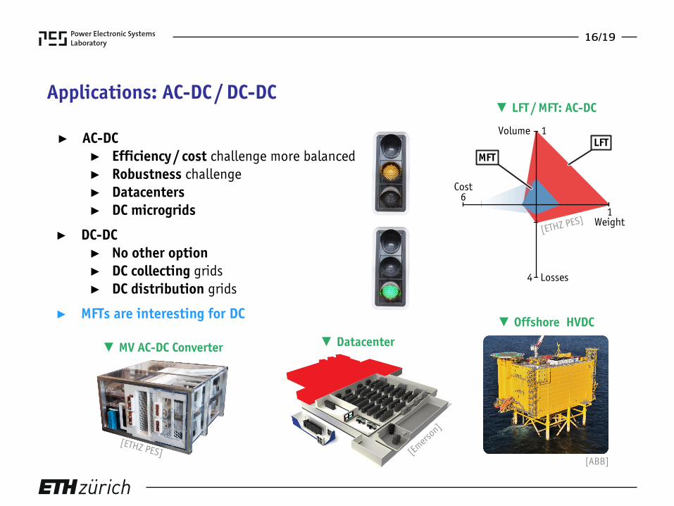
16/19
Applications: AC-DC / DC-DC
► AC-DC ► Efficiency / cost challenge more balanced ► Robustness challenge ► Datacenters ► DC microgrids
► DC-DC ► No other option ► DC collecting grids ► DC distribution grids
► MFTs are interesting for DC
▼ LFT / MFT: AC-DC
[ETHZ PES]
Volume 1
1Weight
6Cost
Losses
4
LFTMFT
▼ MV AC-DC Converter ▼ Datacenter
[ETHZ PES] [Emers
on]
▼ Offshore HVDC
[ABB]

17/19
Applications: Weight / Space Limited
► Electric mobility► Electric traction► MV
/
DC naval applications
► More electric aircrafts
► MFTs offers a competitive advantage
▼ Future Electric Aircraft
▼ MFT-based Traction Chain
▼ MFT-based Locomotive
[ABB]
[ABB]
[NASA]

18/19
Conclusion
► Medium-frequency transformers ► Increased power density ► Increased efficiency
► Challenges ► Require power electronic ► Magnetic / electric design at MF ► Insulation / heat management
► Applications ► AC-DC / DC-DC ► Weight / space constrained
► MFTs are interesting for future grids► MFTs are not replacing LFTs
▼ 450 kW / 8 kHz
[STS Trafo]
▼ 160 kW / 20 kHz
[ETHZ PES]
[ABB]
[Bombardier]
▼ 350 kW / 8 kHz
▼ 150 kW / 1.75 kHz
▼ 6.3 kW / 100 kHz
[ETHZ PES]

19/19
Thank You! Questions? Acknowledgement
Raphael FärberProf. Christian M. Franck
Daniel RothmundMichael LeiblDr. Florian KrismerDr. Jonas HuberDr. Gabriel Ortiz
[1] L. Heinemann, “An Actively Cooled High Power, High Frequency Transformer with High Insulation Capability”, APEC, 2002[2] G. Ortiz et al., “Medium Frequency Transformers for Solid-State-Transformer Applications - Design and Experimental Verification”, PEDS, 2013[3] T. Guillod et al., “Characterization of the Voltage and Electric Field Stresses in Multi-Cell Solid-State Transformers”, ECCE, 2014[4] C. Zhao et al., “Power Electronic Traction Transformer - Medium Voltage Prototype”, IEEE Trans. Ind. Electron., 2014[5] T. Guillod et al., “Computation and Analysis of Dielectric Losses in MV Power Electronic Converter Insulation”, ECCE, 2016
References
Recommended


![[Smart Grid Market Research] India: Smart Grid Legacy, Zpryme Smart Grid Insights, September 2011](https://img.dokumen.tips/doc/110x75/541402518d7f7294698b47d4/smart-grid-market-research-india-smart-grid-legacy-zpryme-smart-grid-insights-september-2011.jpg)
![[Smart Grid Market Research] Smart Grid Index: November 2012 - Zpryme Smart Grid Insights](https://img.dokumen.tips/doc/110x75/541402018d7f728a698b47a5/smart-grid-market-research-smart-grid-index-november-2012-zpryme-smart-grid-insights.jpg)
![[Smart Grid Market Research] Brazil: The Smart Grid Network, Zpryme Smart Grid Insights, October 2011](https://img.dokumen.tips/doc/110x75/577d20871a28ab4e1e931ff6/smart-grid-market-research-brazil-the-smart-grid-network-zpryme-smart-grid.jpg)

![[Smart Grid Market Research] South Korea: Smart Grid Revolution, Zpryme Smart Grid Insights, July 2011](https://img.dokumen.tips/doc/110x75/5414026d8d7f727d698b47c7/smart-grid-market-research-south-korea-smart-grid-revolution-zpryme-smart-grid-insights-july-2011.jpg)