MAX153 1Msps, µP-Compatible, 8-Bit ADC with 1µA Power-Down
General DescriptionThe MAX153 high-speed, microprocessor (µP)-compatible, 8-bit analog-to-digital converter (ADC) uses a half-flash technique to achieve a 660ns conversion time, and digitiz-es at a rate of 1M samples per second (Msps). It operates with single +5V or dual ±5V supplies and accepts either unipolar or bipolar inputs. A POWERDN (power-down) pin reduces current consumption to a typical value of 1µA (with 5V supply). The part returns from power-down to normal operating mode in less than 200ns, providing large reductions in supply current in applications with burst-mode input signals.The MAX153 is DC and dynamically tested. Its µP interface appears as a memory location or input/output port that requires no external interface logic. The data outputs use latched, three-state buffered circuitry for direct connection to a µP data bus or system input port. The ADC’s input/reference arrangement enables ratiometric operation.
Applications CellularTelephones PortableRadios Battery-PoweredSystems Burst-ModeDataAcquisition Digital-SignalProcessing Telecommunications High-SpeedServoLoops
Features 660nsConversionTime Power-Up/Power-Downin200ns InternalTrack/Hold 1MspsThroughput LowPower
40mW (Operating Mode) 5µW (Power-Down Mode)
1MHzFull-PowerBandwidth 20-PinNarrowDIP,SO,andSSOPPackages NoExternalClockRequired Unipolar/BipolarInputs Single+5VorDual±5VSupplies RatiometricReferenceInputs
19-4740; Rev 2; 1/12
Ordering Information appears at end of data sheet.
For related parts and recommended products to use with this part, refer to www.maximintegrated.com/MAX153.related.
Functional Diagram
4-BITFLASHADC
4-BITFLASHADC
(4 LSB)
TIMING AND CONTROLCIRCUITRY
MAX153
GND MODE WR/RDY CS RD INT VSS
THREE-STATE
DRIVERS
D0–D7DATAOUTPINS2–5,14–17
1812
11
VREF+
VREF-
1VIN
PWRDN
4-BITDAC
VREF+16
7 6 3 7 7 19
VDD20
10

MAX153 1Msps, µP-Compatible, 8-Bit ADC with 1µA Power-Down
www.maximintegrated.com Maxim Integrated 2
Electrical Characteristics(VDD = +5V ±5%, VGND=0V;UnipolarInputRange:VSS=GND,VREF+ = 5V, VREF-=GND;BipolarInputRange:VSS = -5V ±5%, VREF+ = 2.5V, VREF-=-2.5V;100%productiontested,specificationsaregivenforRDMode(MODE=GND),TA = TMIN to TMAX, unless otherwise noted.)
(AllvoltagesreferencedtoGND.)VDD ..........................................................................-0.3V to +7VVSS ..........................................................................+0.3V to -7VDigital Input Voltage ............................... +0.3V to (VDD + 0.3V)Digital Output Voltage.............................. -0.3V to (VDD + 0.3V)VREF+, VREF+, VIN ........................ (VSS - 0.3V) to (VDD + 0.3V)Continuous Power Dissipation (TA = +70°C)
PDIP (derate 11.11mW/°C above + 70°C). .................889mW
SO(W)(derate10.00mW/°Cabove+70°C..................800mW SSOP(derate8.00mW/°Cabove+70°C) ...................640mW
OperatingTemperatureRangesMAX153C ...................................................................0 to +70°CMAX153E ........................................................... -40°C to +85°CStorageTemperatureRange ............................ -65°C to +150°CLeadTemperature(soldering,10s) .................................+300°CSolderingTemperature(reflow) .......................................+260°C
Stresses beyond those listed under “Absolute Maximum Ratings” may cause permanent damage to the device. These are stress ratings only, and functional operation of the device at these or any other conditions beyond those indicated in the operational sections of the specifications is not implied. Exposure to absolute maximum rating conditions for extended periods may affect device reliability.
Absolute Maximum Ratings
PARAMETER SYMBOL CONDITIONS MIN TYP MAX UNITS
ACCURACY
Resolution N 8 Bits
TotalUnadjustedError TUE Unipolarrange ±1 LSB
DifferentialNonlinearity DNL Nomissingcodesguaranteed ±1 LSB
Zero-CodeError Bipolarinputrange ±1 LSB
Full-ScaleError Bipolarinputrange ±1 LSB
DYNAMIC SPECIFICATIONS (Note 1)
Signal-to-NoisePlusDistortionNoise SINAD fSAMPLE=1MHz,fIN=195.8kHz 45 dB
TotalHarmonicDistortion THD fSAMPLE=1MHz,fIN=195.8kHz -50 dB
PeakHarmonicorSpurious Noise fSAMPLE=1MHz,fIN=195.8kHz -50 dB
ConversionTime(WR-RDMode)(Note2) tCWR TA = +25°C, tRD < tINTL, CL=20pF 660 ns
ConversionTime(RDMode) tCRDTA = +25°C 700
nsTA = TMIN to TMAX 875
Full-PowerBandwidth VIN = 5VP-P 1 MHz
InputSlewRate 3.14 15 V/µs
ANALOG INPUT InputVoltageRange VIN VREF- VREF+ V
InputLeakageCurrent IIN -5V≤VIN≤+5V ±3 µA
Input Capacitance CIN 22 pF
REFERENCE INPUT
ReferenceResistance RREF 1 2 4 kΩ
VREF+InputVoltageRange VREF- VDD V
VREF-InputVoltageRange VSS VREF+ V

MAX153 1Msps, µP-Compatible, 8-Bit ADC with 1µA Power-Down
www.maximintegrated.com Maxim Integrated 3
Electrical Characteristics (continued)(VDD = +5V ±5%, VGND=0V;UnipolarInputRange:VSS=GND,VREF+ = 5V, VREF-=GND;BipolarInputRange:VSS = -5V ±5%, VREF+ = 2.5V, VREF-=-2.5V;100%productiontested,specificationsaregivenforRDMode(MODE=GND),TA = TMIN to TMAX, unless otherwise noted.)
Note 1: Bipolarinputrange,VIN = ±2.5VP-P.WR-RDmode.Note 2: SeeFigure1forloadcircuit.Parameterdefinedasthetimerequiredfortheoutputtocross+0.8Vor+2.4V.Note 3: Guaranteed by design.Note 4: Tested with CS, RD, PWRDNatCMOSlogiclevels.Power-downcurrentincreasestoseveralhundred)µAatTTLlevels.
PARAMETER SYMBOL CONDITIONS MIN TYP MAX UNITS
LOGIC INPUTS
InputHighVoltage VINHCS, WR, RD, PWRDN 2.4
VMODE 3.5
InputLowVoltage VINLCS, WR, RD, PWRDN 0.8
VMODE 1.5
InputHighCurrent IINH
CS, RD, PWRDN 1
µAWR 3
MODE 50 200
InputLowCurrent IINL CS, WR, RD, PWRDN ±1 µA
InputCapacitance(Note3) CIN CS, WR, RD, PWRDN,MODE 5 8 pF
LOGIC OUTPUTS
OutputLowVoltage VOLISINK = 1.6mA, INT, D0–D7 0.4
VRDY,ISINK = 2.6mA 0.4
OutputHighVoltage VOH ISOURCE = 360µA, INT, D0–D7 4 V
FloatingStateCurrent ILKG D0–D7,RDY ±3 µA
FloatingCapacitance(Note3) COUT D7–D0,RDY 5 8 pF
POWER REQUIREMENTS
PositiveSupplyVoltage VDD ±5%forspecifiedaccuracy 5 V
NegativeSupplyVoltage(UnipolarOperation) VSS GND V
NegativeSupplyVoltage (BipolarOperation) VSS ±5%forspecifiedaccuracy -5 V
VDDSupplyCurrent IDDVCS = VRD = 0V, VPWRDN = 5V
MAX153C 8 15mA
MAX153E 8 20
Power-Down VDD Current VCS = VRD = 5V, VPWRDN=0V(Note4) 1 100 µA
VSSSupplyCurrent ISS VCS = VRD = 0V, VPWRDN = 5V 25 100 µA
Power-Down VSS Current VCS = VRD = 5V, VPWRDN = 0V 12 100 µA
Power-SupplyRejection PSR VDD = 4.75V to 5.25V, VREF+ = 4.75V (max), unipolar mode ±1/16 ±1/4 LSB

MAX153 1Msps, µP-Compatible, 8-Bit ADC with 1µA Power-Down
www.maximintegrated.com Maxim Integrated 4
TIMING CHARACTERISTICS (Note 5)(VDD = +5V ±5%, VSS=0VforUnipolarInputRange,VSS=-5V±5%forBipolarInputRange,100%productiontested,TA = +25°C, unless otherwise noted.)
PARAMETER SYMBOL CONDITIONS MIN TYP MAX UNITS
CS TO RD/WRSetupTime tCSS 0 ns
CS to RD/WRHoldTime tCSH 0 ns
CS to RDYDelay(Note6) tRDYCL=50pF 70
nsTA = TMIN to TMAX, CL=50pF 85
Data-AccessTime(RDMode)(Note2) tACC0
CL=20pF tCRD + 25
nsTA = TMIN to TMAX, CL=20pF tCRD + 30
CL=100pF tCRD + 50
TA = TMIN to TMAX, CL=100pF tCRD + 65
RD to INTDelay(RDMode) tINTHCL=50pF 50 80
nsTA = TMIN to TMAX, CL=50pF 85
Data-HoldTime(Note7) tDH60
nsTA = TMIN to TMAX 70
DelayTimeBetween Conversions (Acquisition Time) tP
160ns
TA = TMIN to TMAX 185
Write Pulse Width tWR0.250 10
µsTA = TMIN to TMAX 0.280 10
DelayTimeBetweenWR and RD Pulses tRD
250ns
TA = TMIN to TMAX 350
RDPulseWidth(WR-RD Mode) Determined by tACC1
tREAD1Figure6 160
nsTA = TMIN to TMAX,Figure6 205
Data-Access Time (WR-RDMode(Note2) tRD < tINL
tACC1
CL=20pF,Figure6 160
nsTA = TMIN to TMAX, CL=20pF,Figure6 205
CL=100pF,Figure6 185
TA = TMIN to TMAX, CL=100pF,Figure6 235
RD to INT Delay tRI150
nsTA = TMIN to TMAX 185
WR to INT Delay tINTLCL=50pF 380 500
nsTA = TMIN to TMAX, CL=50pF 610
RDPulseWidth(WR-RDMode)Determinted by tACC2 tRD > tINTL
tREAD2Figure5 65
nsTA = TMIN to TMAX,Figure5 75
Data-Access Time (WR-RDMode)(Note2) tRD > tINTL
tACC2
CL=20pF,Figure5 65
nsTA = TMIN to TMAX, CL=20pF,Figure5 75
CL=100pF,Figure5 90
TA = TMIN to TMAX, CL=100pF,Figure5 110

MAX153 1Msps, µP-Compatible, 8-Bit ADC with 1µA Power-Down
www.maximintegrated.com Maxim Integrated 5
TIMING CHARACTERISTICS (Note 5) (continued)(VDD = +5V ±5%, VSS=0VforUnipolarInputRange,VSS=-5V±5%forBipolarInputRange,100%productiontested,TA = +25°C, unless otherwise noted.)
Note 5: Input control signals are specified with tr = tt = 5ns, 10% to 90% of +5V and timed from a 1.6V voltage level.Note 6: RL=5.1kΩpullupresistor.Note 7: SeeFigure2forloadcircuit.Parameterdefinedasthetimerequiredfordatalinestochange0.5V.
Figure 1. Load Circuits for Data-Access Time Test Figure 2. Load Circuits for Data-Hold Time Test
PARAMETER SYMBOL CONDITIONS MIN TYP MAX UNITS
WR to INT Delay (Pipelined Mode) tIHWR
CL=50pF 80ns
TA = TMIN to TMAX, CL=50pF 100
Data-Access Time After INT(Note2) tID
CL=20pF 30
nsTA = TMIN to TMAX, CL=20pF 35
CL=100pF 45
TA = TMIN to TMAX, CL=100pF 60
CL3kΩ
DGND
DN
A. HIGH-Z TO VOH B. HIGH-Z TO VOL
CL
3kΩ
DGND
DN
+5V
10pF3kΩ
DGND
DN
A. VOH TO HIGH-Z B. VOL TO HIGH-Z
10pF
3kΩ
DGND
DN
+5V

MAX153 1Msps, µP-Compatible, 8-Bit ADC with 1µA Power-Down
Maxim Integrated 6www.maximintegrated.com
Typical Operating Characteristics
CONVERSION TIMEvs. AMBIENT TEMPERATURE
MAX
153
toc0
1
TEMPERATURE (°C)
t CRD
(NOR
MALIZ
ED T
O VA
LUE
AT +
25°C
)
12010060 80-20 0 20 40-40
0.7
0.8
0.9
1.0
1.1
1.2
1.3
1.4
1.5
0.6-60 140
VDD = +5.25V
VDD = +4.75V
VDD = +5V
SIGNAL-TO-NOISE RATIOMAX153 toc03
-100
0 500400300200100
-80
0
-20
-40
-60
FREQUENCY (kHz)
TA = +25°C
INPUT FREQUENCY= 195.8ksps (±2.5V)SAMPLE FREQUENCY= 1MHzSNR = 49.1dB
RATI
O (d
B)
EFFECTIVE BITS vs. INPUTFREQUENCY, WR-RD MODE
MAX
153
toc0
2
4.0
4.5
5.0
5.5
6.0
6.5
7.0
7.5
8.0
FREQUENCY (kHz)1k10010
EFFE
CTIV
E BI
TS ROOMCOLD -55°C
ISAMPLE = 1MHzVIN = ±2.5V
HOT +125°C
INTERMODULATION DISTORTIONMAX153 toc04
-100
0 25020015010050
-80
0
-20
-40
-60
FREQUENCY (kHz)
TA = +25°C INPUT FREQUENCY= 94.97kHz= 84.72kHz (±2.5V)SAMPLE FREQUENCY= 500kHzIMD: 2ND-ORDER TERMS= -66.2dB3RD-OREDER TERMS= -60.0dB
RATI
O (d
B)

MAX153 1Msps, µP-Compatible, 8-Bit ADC with 1µA Power-Down
www.maximintegrated.com Maxim Integrated 7
Pin Description
Pin Configuration
*See the Digital Interface section.
PIN NAME FUNCTION1 VIN AnalogInput.RangeisVREF- > VIN < VREF+.
2 D0 Three-StateDataOutput(LSB)
3–5 D1–D3 Three-StateDataOutputs
6 WR/RDY WRITEControlInput/READYStatusOutput*
7 MODEMODESelectionInput.Internallypulledlowwitha50µAcurrentsource. MODE=0activatesreadmode. MODE=1activeswrite-readmode*
8 RD READ Input. Must be low to access data*.
9 INT INTERRUPT Output goes low to indicate end of conversion*.
10 GND Ground
11 VREF- LowerLimitofReferenceSpan.Setsthezero-codevoltage.RangeisVSS < VREF-< VREF+.
12 VREF+ UpperLimittoReferenceSpan.Setsthefull-scaleinputvoltage.RangeisVREF-< VREF+< VDD.
13 CS CHIP SELECT Input. Must be low for the device to recognize WR or RD inputs.
14–16 D4–D6 Three-StateDataOutputs
17 D7 Three-StateDataOutput(MSB)
18 PWRDN POWERDOWNInput.Reducessupplycurrentwhenlow.CS must be high during power-down.
19 VSS NegativeSupply.Unipolar:VSS=0V,Bipolar:VSS= -5V.
20 VDD PositiveSupply,+5V
20
19
18
17
16
15
13
1
2
3
4
5
6
8
VDD
VSS
PWRDN
D7 (MSB)D2
D1
D0 (LSB)
VIN
TOP VIEW
MAX153D6
D5
CSRD
WR/RDY
147 D4MODE
1110 VREF-GND
129 VREF+INT
D3
PDIP/SO(W)/SSOP
+

MAX153 1Msps, µP-Compatible, 8-Bit ADC with 1µA Power-Down
www.maximintegrated.com Maxim Integrated 8
Detailed DescriptionConverter OperationThe MAX153 uses a half-flash conversion technique (see the Functional Diagram) in which two 4-bit flash ADC sections achieve an 8-bit result.Using 15 comparators,theflashADCcomparestheunknowninputvoltagetothereference ladder and provides the upper 4 data bits.An internal digital-to-analog converter (DAC) uses the 4 mostsignificantbits(MSBs)togeneratetheanalogresultfrom the first flash conversion and a residue voltage that isthedifferencebetweentheunknowninputandtheDACvoltage. The residue is then compared again with the flashcomparatorstoobtainthelower4databits(LSBs).
Power-Down ModeIn burst-mode or low sample-rate applications, the MAX153 can be shut down between conversions, reduc-ingsupplycurrenttomicroamplevels.ATTL/CMOSlog-ic-low on the PWRDN pin shuts the device down, reduc-ing supply current to typically 1µA when powered from a single 5V supply. CS must be high when power- down is used. A logic-high on PWRDNwakesuptheMAX153.Anew conversion can be started (WR asserted low) within 360ns of the PWRDN pin being driven high 200ns to powerupplus160nsfortrack/holdacquisition).Ifpower-down mode is not required, connect PWRDN to VDD.Once the MAX153 is in power-down mode, lowest sup-ply current is drawnwithMODE low (RDmode)due toan internal 50µA pulldown resistor at this pin. CS must remain high during shutdown because the MAX153 may attempt to start a conversion that it cannot complete. In addition, for minimum current consumption, other digital inputs should remain stable in power-down. RDY, anopen-drainoutput(inRDmode),willthenfallandremainlow throughout. Power-down, sinking additional supplycurrent unless CSremainshigh.SeetheReference sec-tion for information on reducing reference current during power-down.
Digital InterfaceThe MAX153 has two basic interface modes set by the status of theMODE input pin.WhenMODE is low, theconverter is in theRDmode; whenMODE is high, theconverterissetupfortheWR-RDmode.
Read Mode (MODE = 0)InRDmode,conversioncontrolanddataaccessarecon-trolled by the RDinput(Figure3).Thecomparatorinputstrack the analog input voltage for the duration of tP. A minimum of 160ns is required for the input to be acquired. A conversion is initiated by driving RD low. With µPs that can be forced into a wait state, hold RD low until output data appears. The µP starts the conversion, waits, and then reads data with a single read instruction.WR/RDY is configured as a status output (RDY) inRDmode, where it can drive the ready or wait input of a µP. RDYisanopen-collectoroutput(withnointernalpullup)that goes low after the falling edge of CS and goes high at the end of the conversion. If not used, the WR/RDYpincan be left unconnected. The INT output goes low at the end of the conversion and returns high on the rising edge of CS or RD.
Write-Read Mode (MODE = 1)Figures 4 and 5 show the operating sequence for thewrite-read (WR-RD)mode.Thecomparator inputs trackthe analog input voltage for the duration of tP. A minimum of 160ns is required for the input voltage to be acquired. The conversion is initiated by a falling edge of WR. When WRreturnshigh, the4MSBsflashresult is latchedintotheoutputbuffersandthe4LSBsconversionbegins.INTgoes low about 380ns later, indicating conversion end, and the lower 4 data bits are latched into the output buf-fers.Thedataisthenaccessible65nsto130nsafterRDgoes low (see the Timing Characteristics).If an externally controlled conversion time is required, drive RD low 250ns after WR goes high. This latches the lower 4 data bits and outputs the conversion result on D0–07. A minimum 160ns delay is required from INT going low to the start of another conversion (WR going low). Options for reading data from the converter include the following:
Using Internal DelayThe µP waits for the INT output to go low before reading thedata(Figure4).INT typically goes low 380ns after the rising edge of WR, indicating the conversion is complete, and the result is available in the output latch. With CS low, data outputs D0–D7 can be accessed by pulling RD low. INT is then reset by the rising edge of CS or RD.

MAX153 1Msps, µP-Compatible, 8-Bit ADC with 1µA Power-Down
www.maximintegrated.com Maxim Integrated 9
Fastest Conversion: Reading Before DelayAn external method of controlling the conversion time is shown in Figure 5. The internally generated delay tINTLvaries slightly with temperature and supply voltage, and can be overridden with RD to achieve the fastest conversion time. INT is ignored, and RD is brought low typically 250ns after the rising edge of WR. This completes the conversion and enables the output buffers (D0–D7) that contain the conversion result. INT also goes low after the falling edge of RD and is reset on the rising edge of RD or CS. The total conversiontimeistherefore:tCWR = tWR(250ns) + tCSH (0ns) to tRD (250ns) + tACC1
(160ns) = 660ns.
Pipelined OperationBesides the two standardWR-RD mode options, pipe-lined operation can be achieved by connecting WR and RDtogether(Figure6).WithCS low, driving WR and RD low initiates a conversion and reads the result of the previ-ous conversion concurrently.
Analog Considerations ReferenceFigures7a–7cshowsomereferenceconnections.VREF+and VREF- inputs set the full-scale and zero-input voltages of the ADC. The voltage at VREF- defines the input that produces an output code of all zeros, and the voltage at VREF+ defines the input that produces an output code of all ones.
Figure 3. RD Mode Timing (MODE = 0) Figure 5. WR-RD Mode Timing (tRD > tINTL), Fastest Operating Mode (MODE = 1)
Figure 4. WR-RD Mode Timing (tRD > tINTL) (MODE = 1) Figure 6. Pipelined Mode Timing (WR = RD) (MODE = 1)
tP
tINTH
tCSH
tDH
tCRD
tACC0
WITH EXTERNAL PULLUP
tCSS
tRDY
CS
RD
INT
D0–D7 VALID DATA
RDY
VALID DATAtACC2 tDH
tINTH
tCSH
tWR
tCSS
CS
WR
INT
D0–D7
RDtRD
tPtREAD2
tINTL
tCWR
tCSH
tPtRDtCSS
tRI
tREAD1
tACC1 tDH
tINTH
tWR
DATA VALID
CS
WR
RD
INT
D0–D7
tIHWR
tID
tWR
tP
NEW DATAOLD DATA
RD, WR
INT
D0–D7
tINTL

MAX153 1Msps, µP-Compatible, 8-Bit ADC with 1µA Power-Down
www.maximintegrated.com Maxim Integrated 10
The internal resistances from VREF+ and VREF- may be aslowas1kΩ.Sincecurrentisstilldrawnbythereferenceinputs during power-down, reference supply current can be reduced during shutdown by using the circuit shown inFigure7d.Alogic-leveln-channelMOSFET,connectedbetween VREF- and ground, disconnects the reference load when the ADC enters power-down. (PWRDN = low). TheFETshouldhavenomorethan0.5Ωofon-resistanceto maintain accuracy.
BypassingA 4.7µF electrolytic in parallel with a 0.1µF ceramiccapacitor should be used to bypass VDDtoGND.Thesecapacitors should have minimal lead length.The reference inputs should be bypassed with 0.1µFcapacitors,asshowninFigures7a–7c.
Input CurrentFigure 8 shows the equivalent circuit of the converterinput. When the conversion starts and WR is low, VIN is connectedto160.6pFcapacitors.Duringthisacquisitionphase, the input capacitors charge to the input voltage through the resistance of the internal analog switches (about 2kΩ). In addition, about 12pF of stray capaci-tance must be charged. The input can be modeled as an equivalentRCnetwork(Figure9).Assourceimpedanceincreases,thecapacitorstakelongertocharge.The typical22pF inputcapacitanceallowssource resis-tanceashighas2.2kΩwithoutsetupproblems.Forlargerresistances, the acquisition time (tP) must be increased
Figure 7a. Power Supply as Reference
Figure 7b. External Reference, +2.5V Full Scale
Figure 7c. Input Not Referenced to GND
Figure 7d. An n-Channel MOSFET Switches Off the Reference Load During Power-Down
GNDVIN-10
VINVIN+1
VDD
VREF+
VREF-
20
124.7µF0.1µF
+5V
11
MAX153
0.1µF
+2.5V
20
4.7µF0.1µF
+5V
GNDVIN-10
VINVIN+1
VDD
VREF+
VREF-
12
11
MAX153
MAX584
+2.5V
VINVIN+
VIN-
1
GND
VDD
VREF+
VREF-
10
20
124.7µF0.1µF
0.1µF
+5V
11
MAX153
0.1µF*
*CURRENT PATH MUST STILLEXIST FROM VIN- TO GND
MAX584
VDDVIN+
PWRDN
20
VREF+
VREF-
PWRDN
12
11
0.1µF
0.1µF
18
MAX153
0.1µFN-FET
MAX153 1Msps, µP-Compatible, 8-Bit ADC with 1µA Power-Down
www.maximintegrated.com Maxim Integrated 11
Conversion RateThe maximum sampling rate (fMAX) for the MAX153 is achievedintheWR-RDmode(tRD < tINTL) and is calcu-latedasfollows:
MAXWR RD RI P
MAX
MAX
1ft t t t
1f250ns 250ns 150ns 165ns
f 1.23MHz
=+ + +
=+ + +
=
where tWR = Write pulse widthtRD = Delay between WR and RD pulsestRI = RD to INT delaytP = Delay time between conversions
Signal-to-Noise Ratio and Effective Number of BitsSignal-to-noiseratio(SNR)istheratiooftheRMSampli-tude of the fundamental input frequency to the RMSamplitude of all other analog-to-digital output values. The output band is limited to one-half the A/D sample (conver-sion) rate. This ratio usually includes distortion as well as noisecomponents.Forthisreason,theratioissometimesreferred to as signal-to-noise plus distortion.The theoretical minimum A/D noise is caused by quanti-zationerrorandresultsdirectlyfromtheADC’sresolution:SNR=(6.02N+1.76)dB,whereNisthenumberofbitsof resolution. Therefore, a perfect 8-bit ADC can do no betterthan50dB.The FFT plot (Typical Operating Characteristics) shows theresultofsamplingapure200kHzsinusoidata1MHzrate.ThisFFTplotoftheoutputshowstheoutputlevelinvarious spectral bands.
The effective resolution, or effective number of bits, the ADC provides can be measured by transposing the equation that converts resolution to SNR: N = (SNR -1.76)/6.02.
Total Harmonic DistortionTotal harmonic distortion (THD) is the ratio of theRMSsum of all harmonics of the input signal (in the frequency band above DC and below one-half the sample rate) to thefundamentalitself.Thisisexpressedas:
2 2 2 22 3 4 N
1
(V + V +V + ... +V )THD 20 log
V
=
where V1 is thefundamentalRMSamplitude,andV2 to VNaretheamplitudesofthe2ndthroughNthharmonics.
Peak Harmonic or Spurious NoisePeakharmonicorspuriousnoiseistheratioofthefunda-mentalRMSamplitudetotheamplitudeofthenextlargestspectral component (in the frequency band above DC and belowone-halfthesamplerate).Usuallythispeakoccursat some harmonic of the input frequency, but if the ADC is exceptionally linear, itmayoccuronlyatarandompeakin the ADC’s noise floor.
Intermodulation DistortionAnFFTplotof intermodulationdistortion(IMD)isgener-ated by sampling an analog input applied to the ADC. This input consists of very low distortion sine waves at two frequencies. A 2048 point plot for IMD of the MAX153 is shown in the Typical Operating Characteristics.
Figure 8. Equivalent Input Circuit Figure 9. RC Network Equivalent Input Model
VINVIN
RONRIN 1
C
MAX153
VINVIN
2kΩR 1
12pF
MAX153
10pF
MAX153 1Msps, µP-Compatible, 8-Bit ADC with 1µA Power-Down
www.maximintegrated.com Maxim Integrated 12
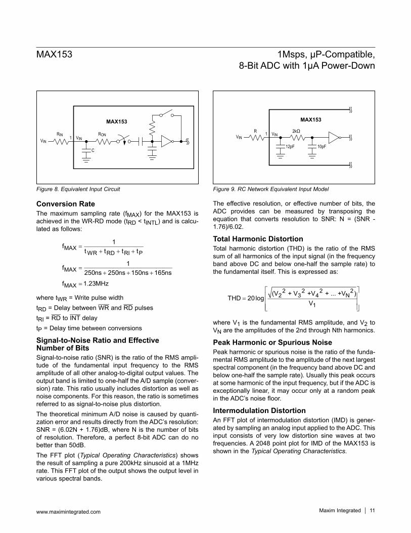
Package InformationFor the latest package outline information and land patterns(footprints), go to www.maximintegrated.com/packages.Notethata“+”,“#”,or“-”inthepackagecodeindicatesRoHSstatusonly.Packagedrawingsmayshowadifferentsuffixcharacter,butthedrawingpertainstothepackageregardlessofRoHSstatus.
Chip InformationPROCESS:BiCMOS
+Denotes a lead(Pb)-free/RoHS-compliant package.*Contact factory for dice specifications.**Contact factory for availability of SSOP packages
Ordering Information
PACKAGE TYPE
PACKAGE CODE
OUTLINE NO.
LAND PATTERN NO.
20 PDIP P20+3 21-0043 —
20SO(W) W20+2 21-0042 90-010820SSOP A20+1 21-0056 90-0094
PART TEMP RANGE PIN-PACKAGEMAX153CAP+ 0°C to +70°C 20SSOP**
MAX153CPP+ 0°C to +70°C 20 PDIP
MAX153CWP+ 0°C to +70°C 20SO(W)
MAX153C/D 0°C to +70°C Dice*
MAX153EAP+ -40°C to +85°C 20SSOP**MAX153EPP+ -40°C to +85°C 20 PDIP
MAX153EWP+ -40°C to +85°C 20WideSO

Maxim Integrated cannot assume responsibility for use of any circuitry other than circuitry entirely embodied in a Maxim Integrated product. No circuit patent licenses are implied. Maxim Integrated reserves the right to change the circuitry and specifications without notice at any time. The parametric values (min and max limits) shown in the Electrical Characteristics table are guaranteed. Other parametric values quoted in this data sheet are provided for guidance.
Maxim Integrated and the Maxim Integrated logo are trademarks of Maxim Integrated Products, Inc.
MAX153 1Msps, µP-Compatible, 8-Bit ADC with 1µA Power-Down
© 2012 Maxim Integrated Products, Inc. 13
Revision HistoryREVISIONNUMBER
REVISION DATE DESCRIPTION PAGES
CHANGED0 7/92 Initial release —
1 10/93 Corrected die topography 11
2 1/12 Removedmilitarypackages 1–5
For pricing, delivery, and ordering information, please contact Maxim Direct at 1-888-629-4642, or visit Maxim Integrated’s website at www.maximintegrated.com.
Recommended


![ADC-20 und ADC-24 › download › datasheets › adc20...Datenlogger ADC-20 und ADC-24 ADC-20 ADC-24 Auflösung 20 Bit 24 Bit Anzahl Kanäle[1] 4 differenzial / 8 einpolig 8 differenzial](https://img.dokumen.tips/doc/110x75/5f23cbdc98bf2e58da663aad/adc-20-und-adc-24-a-download-a-datasheets-a-adc20-datenlogger-adc-20-und.jpg)