MATERIALS CHALLENGES FOR GENERATION IV REACTORS
Stuart A. Maloy Advanced Reactor Core Materials Technical Lead
Nuclear Technology Research and Development Program
February 21, 2018

Meet the presenter
Stuart Maloy is a Team Leader for MST-8 (materials at radiation and dynamic extremes) at Los Alamos National Laboratory(where he has worked for 28 years) and is the advanced reactor core materials technical leader for the Nuclear Technology Research and Development’s Advanced Fuels campaign and the NEET Reactor Materials Technical Lead for DOE-NE. He earned his Bachelors Degree (’89), Masters Degree (’91) and PhD (’94) in Materials Science from Case Western Reserve University and is a registered PE in Metallurgy. He has applied his expertise to characterizing and testing the properties of metallic and ceramic materials in extreme environments such as under neutron and proton irradiation at reactor relevant temperatures. This includes testing the mechanical properties (fracture toughness and tensile properties) of Mod 9Cr-1Mo, HT-9, 316L, 304L, Inconel 718, Al6061-T6 and Al5052 after high energy proton and neutron irradiations using accelerators and fast reactors. Characterization of materials after testing includes using transmission electron microscopy for analyzing defects such as dislocations, twins and second phases, using high resolution electron microscopy to characterize defects at an atomic level and nanoscale mechanical testing. Stuart has >190 peer reviewed technical publications and numerous presentations. r
Email: [email protected] 2

Outline
Radiation Effects in Materials
Materials in Nuclear Reactors – FCC, BCC alloys
Reactor Conditions/Materials Performance Issues• LWR (BWR/PWR)
• Typical materials
• Advanced Reactors (VHTR, SCWR)
• Advanced Fast Reactors (SFR, GFR, MSR)
Summary of Reactor Operating Conditions
Summary of Performance Issues
3

53 dpa,
V/V=28
%52 dpa,
V/V=30
%
34 dpa,
V/V=14
%
Grid-to-Rod Fretting CRUD
Fast Reactor Duct Failure
Davis-Besse Reactor Vessel
Head Degradation
Materials in nuclear systems can fail
4
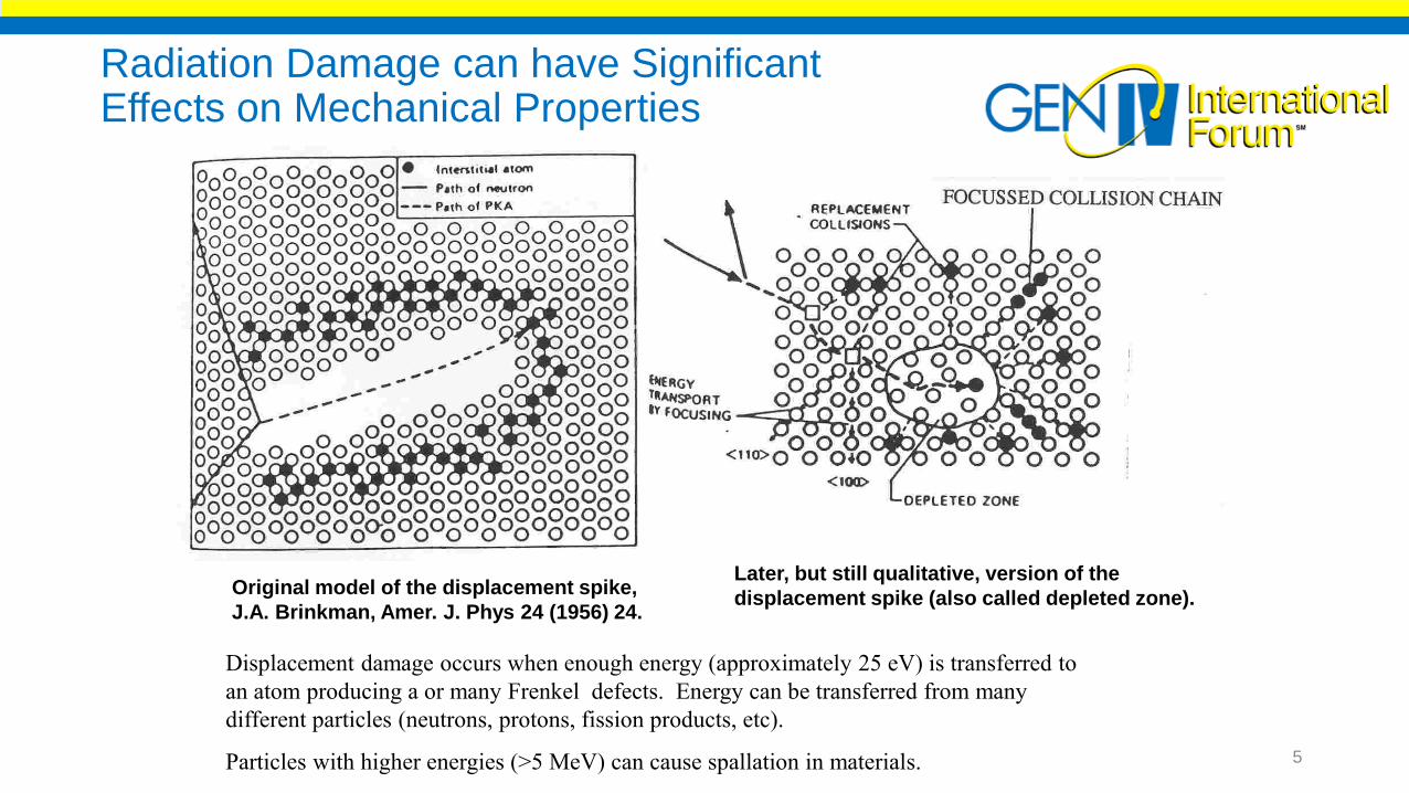
Original model of the displacement spike,
J.A. Brinkman, Amer. J. Phys 24 (1956) 24.
Later, but still qualitative, version of the
displacement spike (also called depleted zone).
Displacement damage occurs when enough energy (approximately 25 eV) is transferred to
an atom producing a or many Frenkel defects. Energy can be transferred from many
different particles (neutrons, protons, fission products, etc).
Particles with higher energies (>5 MeV) can cause spallation in materials.
Radiation Damage can have Significant Effects on Mechanical Properties
5

Background on radiation damage
Creation of Frankel pairs can lead to:
Increase of dislocation density
embrittlement
Formation of voids
swelling
Increased diffusivity
local segregation
Amorphisation or crystallization
unexpected phase changes
2nd Materials property changes due to atomic displacements:
6
Activating the material
Producing new elements leading to He bubble formation and embrittlement e.g. 56Fe(n,a)53Cr or 58Ni(n,a)55Fe
1st Transmutation (changing elements)
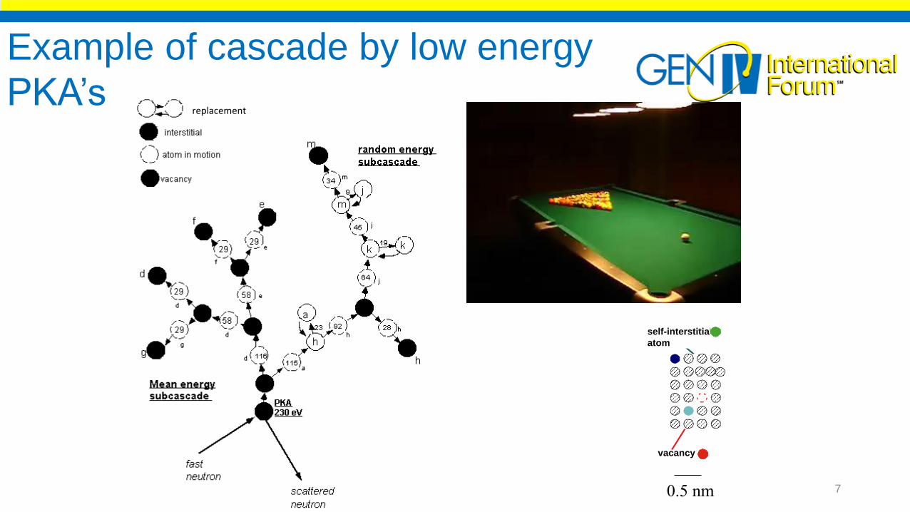
0.5 nm
vacancy
self-interstitial
atom
replacement
Example of cascade by low energy
PKA’s
7
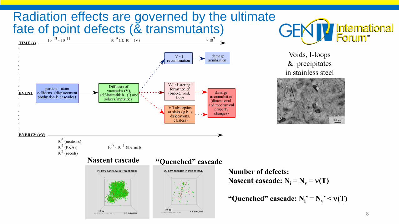
Radiation effects are governed by the ultimate fate of point defects (& transmutants)
particle - atom collisions (displacement production in cascades)
Diffusion ofvacancies (V),
self-interstitials (I) and solutes/impurities
V - Irecombination
damageannihilation
V/I clustering: formation of
(bubble, void,loop)
V/I absorption at sinks (g.b.‘s,
dislocations, clusters)
damageaccumulation (dimensional
and mechanical property changes)
TIME (s)
EVENT
ENERGY (eV)
10-13 - 10-11 10-9 (I); 10-4 (V) > 107
106 (neutrons)
104 (PKAs) 100 - 10-1 (thermal)
102 (recoils)
Nascent cascade
Number of defects:
Nascent cascade: Ni = Nv = n(T)
“Quenched” cascade: Ni’ = Nv’ < n(T)
“Quenched” cascade
Voids, I-loops
& precipitates
in stainless steel
8
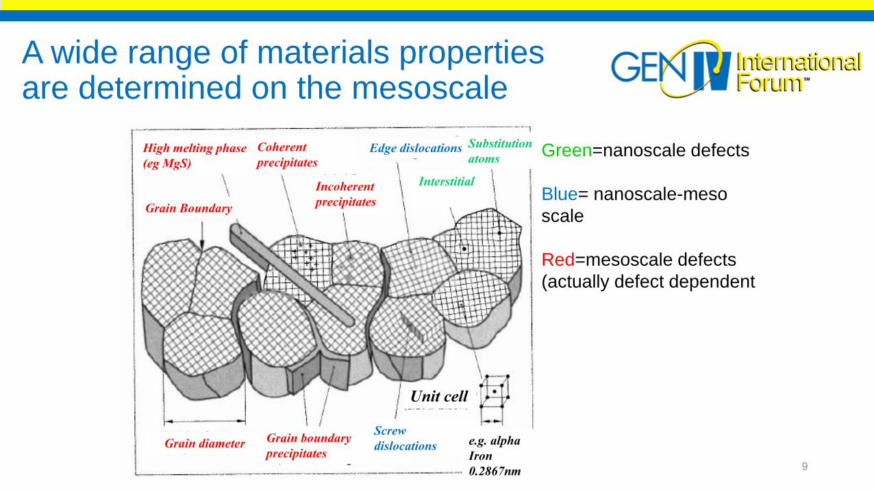
A wide range of materials properties are determined on the mesoscale
High melting phase
(eg MgS)
Coherent
precipitates
Incoherent
precipitates
Edge dislocations
Interstitial
Substitution
atoms
Grain diameter Grain boundary
precipitates
Screw
dislocations
Unit cell
e.g. alpha
Iron
0.2867nm
Grain Boundary
Green=nanoscale defects
Blue= nanoscale-meso
scale
Red=mesoscale defects
(actually defect dependent
9
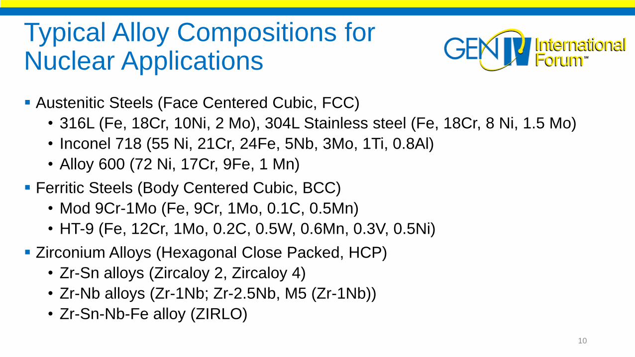
Typical Alloy Compositions for Nuclear Applications
Austenitic Steels (Face Centered Cubic, FCC)
• 316L (Fe, 18Cr, 10Ni, 2 Mo), 304L Stainless steel (Fe, 18Cr, 8 Ni, 1.5 Mo)
• Inconel 718 (55 Ni, 21Cr, 24Fe, 5Nb, 3Mo, 1Ti, 0.8Al)
• Alloy 600 (72 Ni, 17Cr, 9Fe, 1 Mn)
Ferritic Steels (Body Centered Cubic, BCC)
• Mod 9Cr-1Mo (Fe, 9Cr, 1Mo, 0.1C, 0.5Mn)
• HT-9 (Fe, 12Cr, 1Mo, 0.2C, 0.5W, 0.6Mn, 0.3V, 0.5Ni)
Zirconium Alloys (Hexagonal Close Packed, HCP)
• Zr-Sn alloys (Zircaloy 2, Zircaloy 4)
• Zr-Nb alloys (Zr-1Nb; Zr-2.5Nb, M5 (Zr-1Nb))
• Zr-Sn-Nb-Fe alloy (ZIRLO)
10

Radiation Effects in Metals
Defect formation• Basically Frenkel Defects (self interstitials and vacancies)• No charge compensating defects• Very little effect from gamma irradiation• Amorphization is uncommon at typical irradiation
temperatures 25 to 600C
Close Packed Structures• FCC (face centered cubic)-close packed plane is (111)-
Frank loops- atomic packing factor is 0.74• BCC (body centered cubic)-close packed plane is (110)-
atomic packing factor is 0.68• HCP (hexagonal close packed)-for ideal c/a ratio of
1.633, atomic packing factor is same as FCC, 0.74
BCC
FCC11

Useful Operating Temperature Dependent on Melting Temperature and Crystal Structure
At lower temperature (blue region) vacancies are immobile and interstitials are mobile resulting in interstitial clusters andloops and small vacancy clusters.
At medium temperature (gray region) vacancy mobility increases resulting in more self annihilation of defects (vacancy finds interstitial) and possibility of swelling.
At higher temperature (red region) vacancy and interstitial mobility are high leading to problems with creep or helium embrittlement.
S.J. Zinkle and N.M. Ghoniem, Fus. Eng. Des. 51-52 (2000) 55; S.J. Zinkle et al. STAIF2002
0 200 400 600 800 1000 1200 1400
SiC/SiC
CuNiBe
Inconel 718
316 SS
F/M steel
ODS ferritic st.
V-4Cr-4Ti
Nb-1Zr-.1C
Ta-8W-2Hf
Mo (TZM)
W
Estimated Operating Temperature Limits for
Structural Alloys in Fusion Reactors: 10-50 dpa
Temperature (ūC)
BCC
alloys
FCC
alloys
Increasing
Melting
Temperature
12

Irradiation Effects in MetalsA. 316L/304L Stainless Steel (FCC)B. Alloy 718 (FCC)C. Ferritic Steels (BCC)

Irradiation Effects in 316L/304L Stainless Steel (FCC) at 50-200C
14

0.7 dpa 9.8 dpa3.8 dpa
Irradiated with 800
MeV proton beam at
30-50C
no helium clusters
are observed
loops mainly from
collection of
interstitials
TEM images Showing the Growth of Frank Loops in 304L
15

Dislocation Loops Show a Saturation in Density around 4 dpa
Dose
dpa
Number
Loop
Density
m-3
Mean
Loop
Diameter
nm
Total
Dislocation
Density
m-2
0.7
1.6x10²²
1.8
9.0x10¹³
3.8
5x10²²
9.6
1.51x10¹⁵
9.8
2.1x10²²
20.1
1.32x10¹⁵
Loop
Number
16

Stress/Strain Curves show increase in yield stress and decrease in elongation in 316L Stainless steel after irradiation
Stress/Strain Curves for 316L Stainless Steel
0
100
200
300
400
500
600
700
800
900
1000
0 10 20 30 40 50 60
Strain (%)
Str
es
s (
MP
a)
9.3 dpa
2.9 dpa
1.1 dpa
Tt =Tirr= 50C
0.09 dpa
Unirradiated
17

100 nm
Ttest=Tirr=270˚Cg=
011
Irradiated Materials Suffer Plastic Instability due to Dislocation Channeling
18

Change in the Tensile Properties with Dose for 304L and 316L Stainless Steel for Tirr=50-160C
0
200
400
600
800
1000
0
10
20
30
40
50
60
70
80
0 2 4 6 8 10
Uniform Elongation and Yield Stress vs. Dose
for 316L/304L Stainless Steel
YS(304L)YS(316L)
UE (304L)UE(316L)
Yie
ld S
tre
ss (
MP
a)
Un
iform
Elo
nga
tion
(%)
Dose (dpa)19

SEM Images of Fracture Surfaces of 316L Stainless Steel (dose = 9dpa) tensile specimen
20
Irradiation Effects in Inconel 718 (FCC) at 50-200C
21
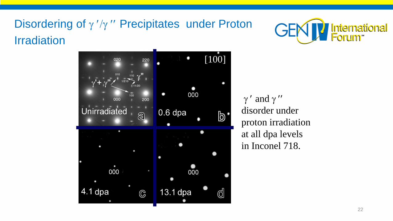
Disordering of Precipitates under Proton
Irradiation
and
disorder under
proton irradiation
at all dpa levels
in Inconel 718.
[100]
22
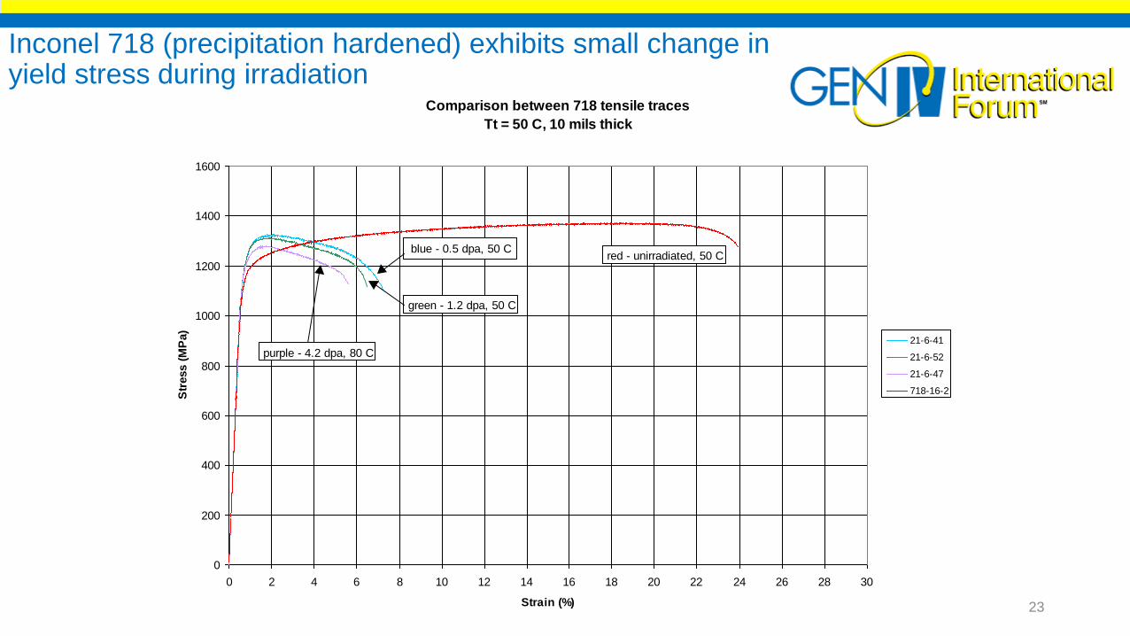
Inconel 718 (precipitation hardened) exhibits small change in yield stress during irradiation
Comparison between 718 tensile traces
Tt = 50 C, 10 mils thick
0
200
400
600
800
1000
1200
1400
1600
0 2 4 6 8 10 12 14 16 18 20 22 24 26 28 30
Strain (%)
Str
ess (
MP
a)
21-6-41
21-6-52
21-6-47
718-16-2
green - 1.2 dpa, 50 C
blue - 0.5 dpa, 50 C
purple - 4.2 dpa, 80 C
red - unirradiated, 50 C
23
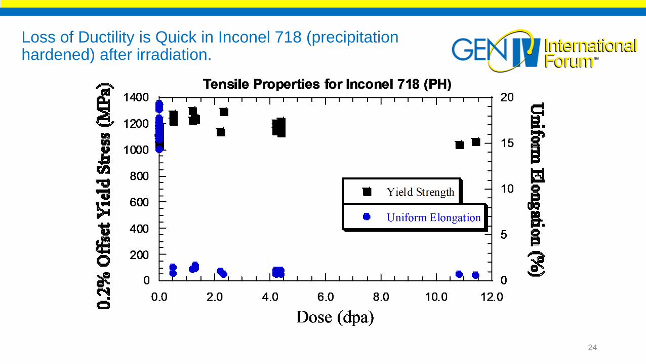
Loss of Ductility is Quick in Inconel 718 (precipitation hardened) after irradiation.
24

At higher doses fracture appearance changes to intergranularfailure in Irradiated Alloy 718
0 dpa 4.6 dpa 10.5 dpa 19.8 dpa
Total elongation is zero at 19.8 dpa 25

Can we vary alloy composition to improve radiation tolerance (e.g. add precipitates or solutes)?
Do other metal alloys show promise?S.J. Zinkle and N.M. Ghoniem, Fus. Eng. Des. 51-52 (2000) 55; S.J. Zinkle et al. STAIF2002
0 200 400 600 800 1000 1200 1400
SiC/SiC
CuNiBe
Inconel 718
316 SS
F/M steel
ODS ferritic st.
V-4Cr-4Ti
Nb-1Zr-.1C
Ta-8W-2Hf
Mo (TZM)
W
Estimated Operating Temperature Limits for
Structural Alloys in Fusion Reactors: 10-50 dpa
Temperature (ūC)
BCC
alloys
FCC
alloys
Increasing
Melting
Temperature
Refractory alloys experience embrittlement
issues due to interstitial pickup (e.g. N, C
or H), swelling and irradiation hardening.
FCC alloys run into swelling,
segregation and precipitation
leading to embrittlement
ZircaloysHCP
alloys Hydrogen Embrittlement
Survey of Materials Limits over higher doses to 200 dpa
26
Irradiation Effects in Mod 9Cr-1Mo and HT-9 (BCC) at 50-400C
27
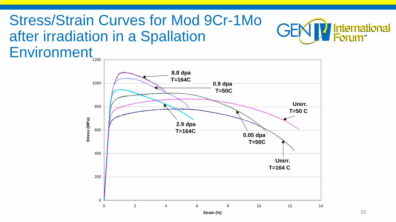
Stress/Strain Curves for Mod 9Cr-1Mo
0
200
400
600
800
1000
1200
0 2 4 6 8 10 12 14
Strain (%)
Str
es
s (
MP
a)
Unirr.
T=164 C
Unirr.
T=50 C
0.05 dpa
T=50C
2.9 dpa
T=164C
0.9 dpa
T=50C
8.8 dpa
T=164C
Stress/Strain Curves for Mod 9Cr-1Mo after irradiation in a Spallation Environment
28

The Change in the Tensile properties with dose for Mod9Cr-1Mo
0
200
400
600
800
1000
1200
0
1
2
3
4
5
6
7
0 2 4 6 8 10
Yield Stress and Uniform Elongation vs. Dose
for Mod 9Cr-1Mo
Yield stress (MPa)
UE (%)
Yie
ld s
tress
(M
Pa)
Un
iform
Elo
ng
atio
n (%
)
Dose (dpa)29
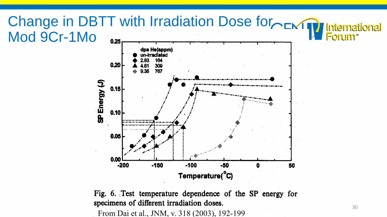
From Dai et al., JNM, v. 318 (2003), 192-199
Change in DBTT with Irradiation Dose for Mod 9Cr-1Mo
30

The ACO-3 duct was analyzed after irradiation in the Fast Flux Test Facility
FFTF, Hanford site, WA
235 4 1
31

Mechanical Test Results on ACO-3 Duct Show Strong Effects of Irradiation Temperature
32
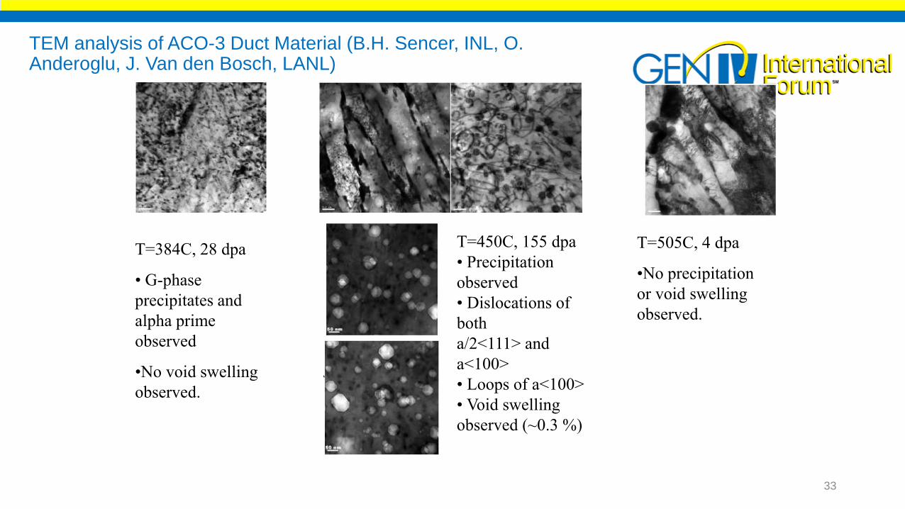
TEM analysis of ACO-3 Duct Material (B.H. Sencer, INL, O. Anderoglu, J. Van den Bosch, LANL)
T=384C, 28 dpa
• G-phase
precipitates and
alpha prime
observed
•No void swelling
observed.
T=450C, 155 dpa
• Precipitation
observed
• Dislocations of
both
a/2<111> and
a<100>
• Loops of a<100>
• Void swelling
observed (~0.3 %)
T=505C, 4 dpa
•No precipitation
or void swelling
observed.
33
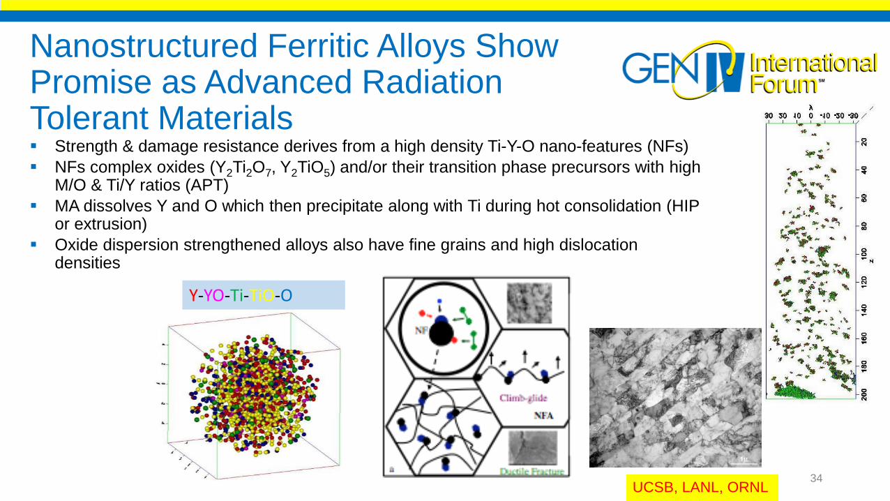
Nanostructured Ferritic Alloys Show Promise as Advanced Radiation Tolerant Materials Strength & damage resistance derives from a high density Ti-Y-O nano-features (NFs)
NFs complex oxides (Y2Ti2O7, Y2TiO5) and/or their transition phase precursors with high M/O & Ti/Y ratios (APT)
MA dissolves Y and O which then precipitate along with Ti during hot consolidation (HIP or extrusion)
Oxide dispersion strengthened alloys also have fine grains and high dislocation densities
Y-YO-Ti-TiO-O
UCSB, LANL, ORNL34
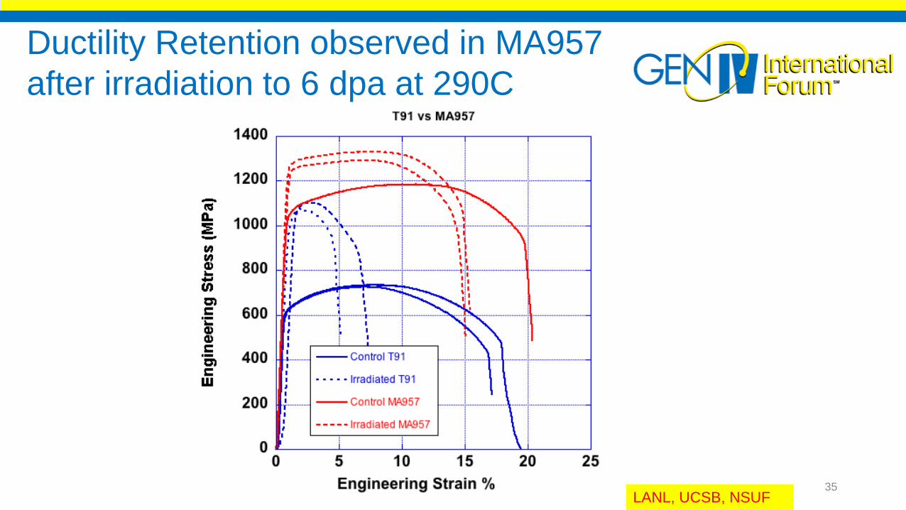
LANL, UCSB, NSUF
Ductility Retention observed in MA957
after irradiation to 6 dpa at 290C
35
Reactor Conditions/Materials PerformanceBWR/LWRGen IV Reactors
VHTR- SCWRSFR-LFR-MSR
36
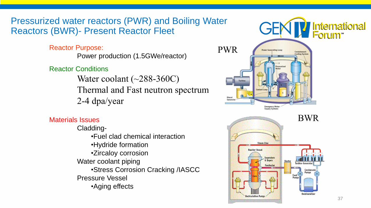
Pressurized water reactors (PWR) and Boiling Water Reactors (BWR)- Present Reactor Fleet
Reactor Purpose:
Power production (1.5GWe/reactor)
Reactor Conditions
Water coolant (~288-360C)
Thermal and Fast neutron spectrum
2-4 dpa/year
Materials Issues
Cladding-
•Fuel clad chemical interaction
•Hydride formation
•Zircaloy corrosion
Water coolant piping
•Stress Corrosion Cracking /IASCC
Pressure Vessel
•Aging effects
PWR
BWR
37

Construction materials for current reactor designs are diverse
LWR SFR GFR/VHTR
Coolant Water Sodium Helium
Temperature 288-360°C 400-550°C 550-1100°C
Cladding Zirconium-based 9 or 12Cr steels SiC/SiC
Core Internals 304/316 SS 316 SS SiC/Alloy 800H
Vessel Steel/308 SS 316 SS Steel/316 SS
Heat Exchanger Alloy 600/690 9-12Cr/316 SS Alloy 617
Piping 304/316 SS 9-12Cr/316 SS Alloy 617
Despite considerable differences in operating parameters, there are common
material uses between LWR and SFR applications
38
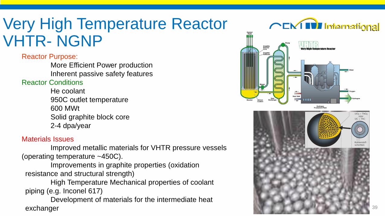
Reactor Purpose:
More Efficient Power production
Inherent passive safety features
Reactor Conditions
He coolant
950C outlet temperature
600 MWt
Solid graphite block core
2-4 dpa/year
Materials Issues
Improved metallic materials for VHTR pressure vessels
(operating temperature ~450C).
Improvements in graphite properties (oxidation
resistance and structural strength)
High Temperature Mechanical properties of coolant
piping (e.g. Inconel 617)
Development of materials for the intermediate heat
exchanger
Very High Temperature Reactor VHTR- NGNP
39
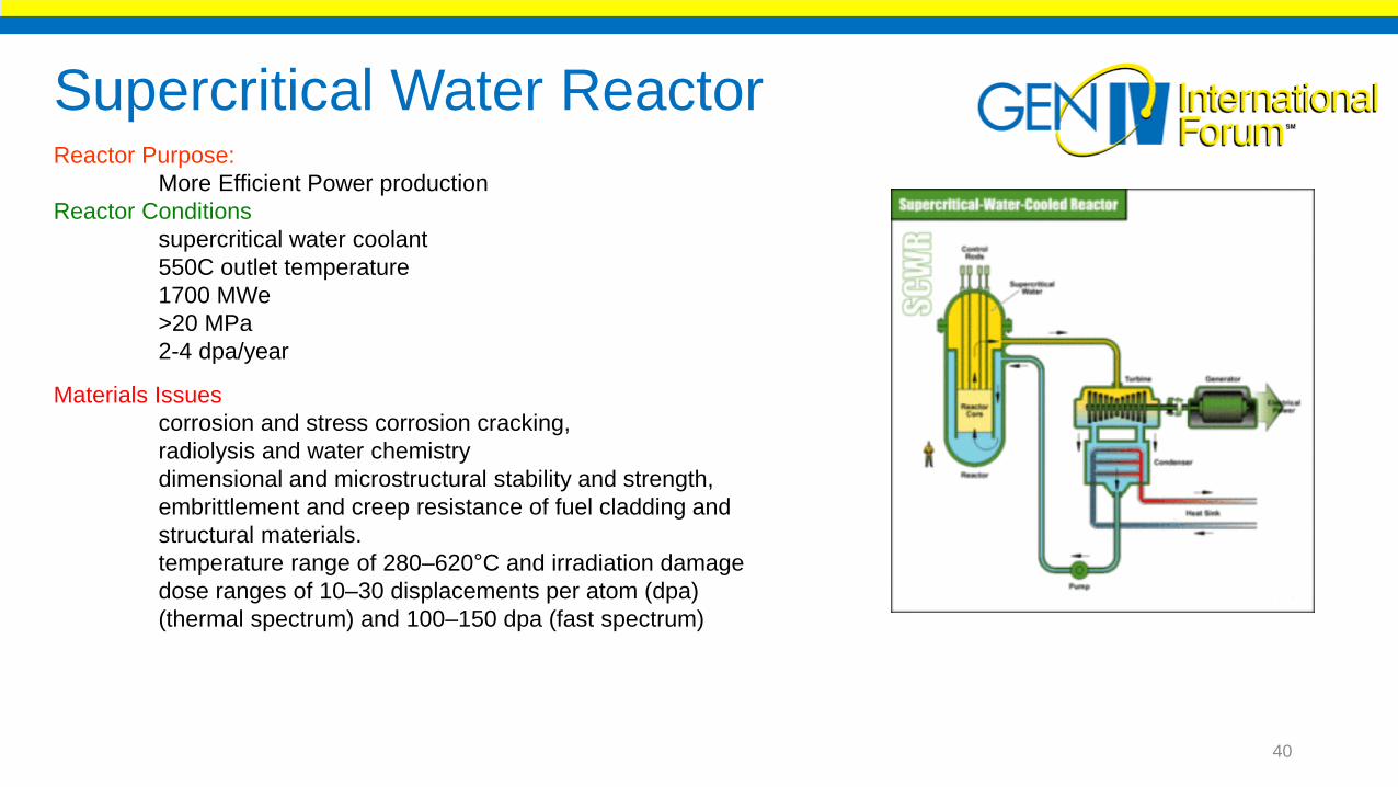
Supercritical Water ReactorReactor Purpose:
More Efficient Power production
Reactor Conditions
supercritical water coolant
550C outlet temperature
1700 MWe
>20 MPa
2-4 dpa/year
Materials Issues
corrosion and stress corrosion cracking,
radiolysis and water chemistry
dimensional and microstructural stability and strength,
embrittlement and creep resistance of fuel cladding and
structural materials.
temperature range of 280–620°C and irradiation damage
dose ranges of 10–30 displacements per atom (dpa)
(thermal spectrum) and 100–150 dpa (fast spectrum)
40

Why Fast reactors?
0
1
10
100
1000
10000
10 100 1000 10000 100000 1000000
Re
lati
ve R
ad
ioto
xic
ity
Time (Years)
Spent Fuel
Pu, U, and Minor Actinides
Removed
Fission
Products
Natural Uranium Ore
300 Years 9,000 Years 300,000 Years
Separation
of Pu and U
Transmutation
of minor actinides
LWR Fuel 5 Years Cooling
Fast reactors are able to address the back
end of the fuel cycle
Produce energy out of waste
Extend the fuel resources
41

Sodium cooled fast reactor/ Lead Fast Reactor
Swelling in 316L SS
Reactor Purpose:
High level nuclear waste Transmutation
Power production
Actinide management
Reactor Conditions
Na, Pb or Pb/Bi coolant
550C to 800C outlet temperature
20-30 dpa/year
Materials Issues
In Core-
High dose irradiation effects
FCCI
Liquid metal corrosion
Lead corrosion of materials
Liquid metal embrittlement
42

Gas cooled fast reactorReactor Purpose:
High level nuclear waste Transmutation
More efficient Power production
Actinide management
Reactor Conditions
He or Supercritical CO2 coolant
850C outlet temperature
Several Fuel options and core configurations
20-30 dpa/year
Materials Issues
Fuel development (must achieve high-power density
and retain fission gases at high burnup and temperature)
Proposed fuel is a composite ceramic (CERCER) with
closely packed and coated actinide carbide kernels or fibers.
Alternative fuel concepts
fuel particles with large kernels and thin coatings
and ceramic-clad solid solutions.
Nitride compounds, enriched 99.9% in N-15
43
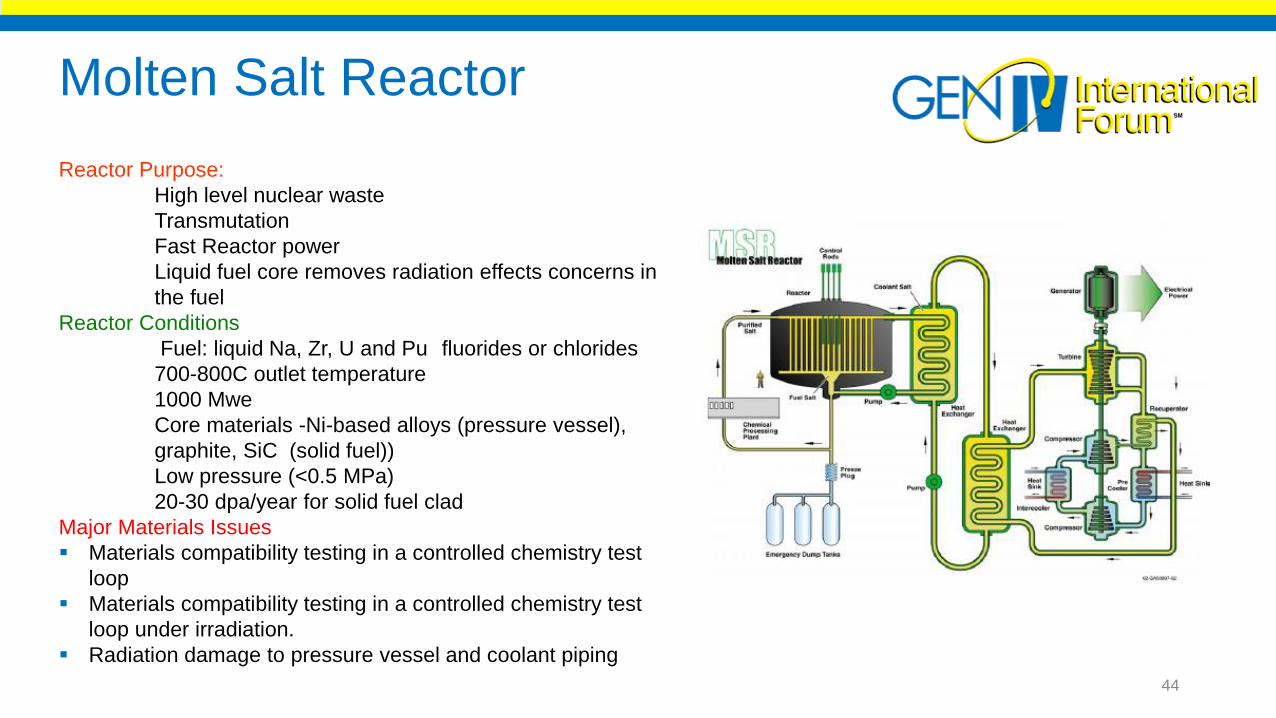
Reactor Purpose:
High level nuclear waste
Transmutation
Fast Reactor power
Liquid fuel core removes radiation effects concerns in
the fuel
Reactor Conditions
Fuel: liquid Na, Zr, U and Pu fluorides or chlorides
700-800C outlet temperature
1000 Mwe
Core materials -Ni-based alloys (pressure vessel),
graphite, SiC (solid fuel))
Low pressure (<0.5 MPa)
20-30 dpa/year for solid fuel clad
Major Materials Issues
Materials compatibility testing in a controlled chemistry test
loop
Materials compatibility testing in a controlled chemistry test
loop under irradiation.
Radiation damage to pressure vessel and coolant piping
Molten Salt Reactor
44

Summary Reactor Operating Conditions
45

Summary of Materials Performance Issues Reactor type Primary Materials Performance Issues
Light Water
Reactors
(PWR/BWR)
Ferritic pressure vessel steels, Fe-
based austenitic stainless steels,
zirconium alloys
IGSCC, IASCC, Fuel clad
mechanical interaction, hydriding,
Radiation embrittlement (DBTT),
hydrogen embrittlement
Very High
Temperature
Reactor (VHTR)
Ni-based superalloys, Graphite,
ferritic/martensitic steels, W/Mo
Alloys, SiC/SiC composites
Helium embrittlement, creep
strength, swelling, RIS,
transmutation, toughness, oxidation
Sodium Fast
Reactor (SFR)
Fe-based austenitic SS,
Ferritic/martensitic steels,
Radiation Embrittlement (DBTT),
toughness, helium embrittlement,
swelling, RIS, corrosion, FCCI
Lead Fast
Reactor (LFR)
Fe-based austenitic SS,
Ferritic/martensitic steels,
Radiation Embrittlement (DBTT),
toughness, helium embrittlement,
swelling, RIS, corrosion, FCCI, liquid
metal embrittlement
Supercritical
Water Reactor
(SCWR)
Ferritic pressure vessel steels, Fe-
based austenitic stainless steels,
zirconium alloys,
ferritic/martensitic steels
IGSCC, IASCC, Fuel clad
mechanical interaction, hydriding,
Radiation/helium embrittlement
(DBTT), swelling, RIS, corrosion,
toughness
Gas Fast
Reactor
Ceramics (carbides, nitrides),
ceramic composites, nickel
superalloys
Helium embrittlement, creep
strength, swelling, RIS,
transmutation, toughness, oxidation
Molten Salt
Reactor
Ni-based alloys, graphite, coatings Corrosion, Helium embrittlement,
creep strength, swelling, RIS,
transmutation, toughness, oxidation
Void development in
HT-9, 155 dpa
316l steel tube after
irradiation46
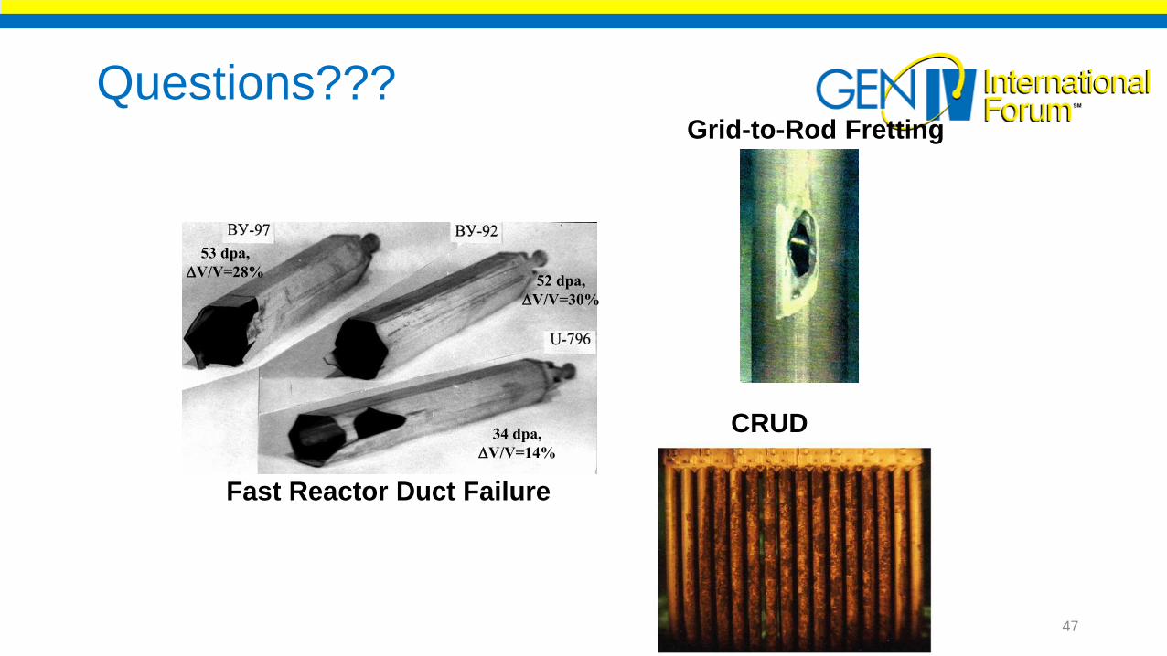
Questions???
53 dpa,
V/V=28%52 dpa,
V/V=30%
34 dpa,
V/V=14%
Grid-to-Rod Fretting
CRUD
Fast Reactor Duct Failure
47
Upcoming webinars
21 March 2018 SCK•CEN’s R&D on MYRRHA Prof. Dr. H.C. Hamid Ait Abderrahim, SCK-CEN, Belgium
18 April 2018 Russia BN 600 and BN 800 Dr. Iiuri Ashurko, Institute of Power and Engineering, Russia
23 May 2018 Proliferation Resistance of Gen IV Systems Dr. Robert Bari, Brookhaven National Laboratory, USA

http://gifsymposium2018.gen-4.org/
Call for abstracts Extended Deadline - 31 March 2018
Track 1 & 2: Progress on Gen IV systemsTrack 3: Human capital developmentTrack 4: Research infrastructuresTrack 5: Safety and securityTrack 6: Fuels and materialsTrack 7: Advanced components and systems for Gen IV reactorsTrack 8: Integration of nuclear reactors in low carbon energy systemsTrack 9: Decommissioning & Waste ManagementTrack 10: Operation, Maintenance, Simulation & TrainingTrack 11: Construction of nuclear reactors
The symposium has two major objectives:
•to review the progress achieved for each system against the R&D goals of the 2014 Technology Roadmap Update.
•to identify the remaining challenges and associated R&D goals for the next decade necessary for the demonstration and/or deployment of the Gen IV systems, and the goal of establishing nuclear energy as a necessary element in the world’s long-term sustainable carbon-free energy mix.
MSc and PhD students, young professionals, policy makers and nuclear stakeholders are encouraged to participate
Recommended