..“
.-
~~~~~“”””” ““’”;.......... ..-.—
Par”& ~ “.”.“.Manua,..::...B43M’=GAO16IndustrialEngines
. .
,...
-,, .... ...... .~.—-m<-,=
‘4
,.,.-
..
965-025411-88 (Spec A-C)Replaces 5-85 (Spec A-C)Printed in U.S.A. ~

—.—
/<-.‘\
-.
For parts or service, contact-the dealer frorn._whorn you purchased this equipment or. refer to your Nearest,-
Authorized Onan Parts and Service Center.
To avoid errors or delay in”filling your parts order, always give the MODEL, ~PEC” NO. and SERIAL NO. -from theOnan nameplate. ~ ...
0 0
MODEL AND SPEC NO.
SERIAL NO..=
,.-.,,,’ ,
I.
M-1149
For handy reference, insert “YOUR”nameplate information in the spaces above.
.,,.
..2
Std. #36D
—.

Index
Adapter, Clutch 46Adapter, Exhaust (Flange Type) 49Adapter, Governor Arm 26,34Adapter, Oil Filter 36,41Air Cleaner-Remote 45Ammeter 34,35Arm, Governor Control 25Armature, Starter 21.37,38
Baffle, Breather Valve 4Ball, Governor 11Base, Oil 8Base, Remote Oil Filter 36Bearing, Camshaft 4Bearing, Crankshaft 4Block, Cylinder 4Block, Terminal (4 Place) 43Box, Breaker 19,20,42Bracket, Governor Control 12,26Bracket, Lifting 48Brush, Ground-Starter 21,37,38
Cable, Choke 34.35Cable, Spark Plug 19,44Camshaft 11Cap, Fuel Tank 33Carburetor Components (Gasoline) 16,28,31,32Carburetor, Gasoline 14,27Clamp, Muffler 49Coil, Ignition 19,44Condenser, Ignition 20,42Cover, Air-Cleaner 14,48Cover, Breaker Box 20,42
/T Cover, Dust-Starter 21,38Cover, Valve 4Crankshaft 10
Drain, Oil Filter 41
Element, Air Cleaner 14Extension, Governor Arm 35
Filter, Breather Tube 14,45Filter, Oil 41,48Flywheel 10
Gasket, Breaker Box 19,20,42Gasket, Cylinder Head 4Gasket, Exhaust Adapter 49Gasket, Oil Base 8Gasket, Valve Cover 4Gauge, Oil Pressure 34,35Gear, Camshaft 11Gear, Crankshaft 10Gear, Ring 10Gearcase 7Governor 12,25,26Guard, Flywheel 10,48
Harness, Wiring 35Head, Cylinder 4Holder, Brush 21,38Hose, Fuel 27Hose, Vacuum 14,27Housing, Air 18
Housing, Air Cleaner 14Housing, Blower 18Housing, Cylinder 18Housing, Starter 21,38
Kit, Adapter - Remote Air Cleaner 45Kit, Alternator Connector 23,24Kit, Clutch 46Kit, Fuel Tank 33Kit, Gasket - Engine 4Kit, Repair - Carburetor 16,28,31,32Kit, Repair – Starter 21,38Kit, Tuneup - Ignition 20,42
Lever, Choke 47Lever, Throttle Control 34)35Line, Fuel - Gasoline 33Line, Oil - Flexible 34,35
Manifold, Exhaust 49Manifold, Intake 14Muffler, Exhaust 49
Numerical Index 50,51,52,53
Panel, Control 34,35Pipe, Exhaust 49Piston 6Plate, Bearing - Rear 4Plug, Spark 19,44Pump, Fuel-Electric (Gasoline) 40Pump, Fuel-Vacuum (Gasoline) 27,30Pump, Oil 8
Regulator, Voltage 23,24Relay, Start Solenoid 21,37,38Ring, Piston 6Rod, Connecting 6Rod, Control-Governor 12,25
Seal, Oil 4,7Seat, Valve 4Sender, Oil Pressure (Electric) 48Spring, Governor 12,25,26,34,35Starter 21,38Starter Components 21,37,38Starter, Recoil 39Stator 23,24,44Strap, Fuel Tank 33Switch, Ignition 34,35Switch, Pressure-Oil 48
Tank, Fuel 33,48Tappet, Valve 4Tube, Air Intake 14,48Tube, Breather 14,45Tube, Oil 4Tube, Vacuum Port 7,27
Valve, Exhaust 4Valve, Intake 4Valve, Shut-Off 33
Wrapper, Filter Element 48
1

Introduction
This cata~og applies to the Standard B43M-GA016 Engines. Parts are arranged in groupsof related items. Each illustrated part is identified bv a reference number /-corresponding to the same reference number in the parts ‘list for that group, Parts
~.
illustrations are typical. Using the MODEL and SPEC NO. from the nameplate, select theParts that apply to your engine. Unless otherwise mentioned in the description, partsare in’cerch.angeable between model’s, Right and left sides are determined by facing theblower end (front) of the engine.
WARNING
This engine is not designed or intended far use in any type of aircraft.Use of this engjne in alrcra-ft may result in engine failure and causeserious bodily Injury, death andlor property damage.
NOTICE !
Items referenced as optional indicate part is factory installed and manot be a
?7licable to all models. YFor field conversions additional par s
are usua y required. ,,,
,-
2

/“7,
c.
. .
3

Cylinder Block
-30r_,/ 4 ‘21
.14
./’- ‘,
.-..
-.
’45
~,-
C.1082
,.>,
40
/
4
Cylinder Block
n, REF PART QTYNO. NO. USED
PARTDESCRIPTION
Block Assembly, Cylinder (AllReplacement Cylinder BlockAssemblies Use Intake ValveSeals and Include PartsMarked *)Engines with Standard RearBearing PlateEngines with 4 Boss BearingPlate
Engines with SAE A or SAE BRear Bearing Plate (DoesNot Include Rear BearingPlate)
*Plug, Welch (1–5/8”) CamshaftOpening
*Screw, Cap - Hex Head(3/8-16 X 1-1/4”)
*Shim, Crankshaft End Play(.005”)
Bearing, Crankshaft - Rear(Includes Thrust Washer)*Standard.002” Undersize.010” Undersize.020” Undersize,030” Undersize
*Washer, Thrust*Gasket, Bearing PlatePlate, Bearing - Rear*StandardOptional - 4 BossOptional - SAE BOptional - SAE A
*Bearing, CamshaftSeal, Oil - Crankshaft Rear
*Pin, Drive - Bearing Stop*Tube, Oil - Cylinder BlockInsert, Valve Seat - Exhaust*Standard.002” Oversize.005” Oversize.010” Oversize.025” Oversize
Insert, Valve Seat – Intake*Standard.002” Oversize.005” Oversize.010” Oversize.025” Oversize
Bearing, Crankshaft - FrontF 1anged*Standard,002” Undersize.010” Undersize,020” Undersize.030” Undersize
Guide, ValveEngines w/o Intake ValveSealsIntakeExhaust
Engines with Intake ValveSeals*Exhaust*Intake
REF PARTNO. NO.
QTY PARTUSED DESCRIPTION
2 *Gasket Intake Valve GuideVacuum Port
Tube - Early ModelsPlug, Breather Hole -Later Models
*Washer, Lock - Spring (3/8”)*Pin, Gear Cover AlignmentReed, Breather ValveBaffle, Breather ValveSpring, Breather ValveCover, Valve - RHCover, Valve - LHGasket, Valve CoverTappet, Valve
Standard,002” Oversize.005” Oversize
Valve, IntakeValve, ExhaustScrew, Cap - Hex Head(1/4-20 X 1-3/4”)
Spring, ValveLock, Valve SpringSeal, Valve - Intake(Optional)
Screw, Socket – Set(3/8-16 X 5/8”)
Gasket, Cylinder HeadStandardOptional (Graphoil)
Head, CylinderRight Side - Spec ALeft Side - Spec ALeft Side - Begin Spec BRight Side - Begin Spec B
Roto Cap - ValveWasher, Flat (1/4” Screw)Washer, Flat (5/16” Screw)Screw, Cap - Hex Head (Special)
5/16-18 X 1-5/8”2“ Long
Washer, Flat - Copper(1/4” Screw)
Plug, Core HoleWasher, Intake Valve SpringRetainer (Optional)
Kit, GasketValve Grind/Carbon Removal(Standard Head Gaskets)
Valve Grind/Carbon Removal(Graphoil Head Gaskets)
Gasket Kit, Complete(Standard Head Gaskets)
Gasket Kit, Complete(Graphoil Head Gaskets)
1 17 110-006818
149-1299517-0120
11
110-3148 1
110-3151 1
110-3154 1
192021222324252627
850-0050516-0141123-1175123-1173123-1174110-1879110-2274110-1921
52111113
517-0048 1
BOO-0051 5
104-0776 AR
2
3
4
5
115-0006115-0006-02115-0006-05110-2368110-1955800-0010
110-0539110-0639509-0168
444
282930
22.2
101-0450 1101-0450-02 1101-0450-10 1101-0450-20 1101-0450-30 1104-0575 2101-0415 1
313233
482
34 803-0071 2678
36110-2287110-3181
22101-0439 1
101-0551 1101-0430 1101-0437 1101-0405 2509-0041 1516-0072 4120-0735 1
37110-2564110-2563110-2561110-2562110-0904526-0018526-0122
800-0540800-0571526-0063
111141
18
1:111213
38394041110-1824 2
110-1824-02 2110-1824-05 2110-1824-10 2110-1824-25 2
126242
14 4344
517-0067110-0893
12110-0197 2
110-0197-02 2110-0197-05 2110-0197-10 2110-0197-25 2
45168-0140
168-0183
168-0153
168-0182
1
15 1
101-0432 1101-0432-02 1101-0432-10 1101-0432-20 1101-0432-30 1
1
1...
16,.- * – parts Included in the Cylinder Block Assembly.
110-1807 2110-1807 2
110-1807 2110-3161 2
/-.
5

Piston and Rod
/1
CT-1055
REF PARTNO. NO.
.1
112-0186112-0186-05112.-Olg6-lO112-0186-20112-0186’-30112-0186-40
2 112-02293 518-03114
113-0189113-0189-05113-0189-10113-0189-20113-0189--30113-0189-40
QTYUSED
22222224
222222
PARTDESCRIPTION
Piston and Pin (IncludesRetaining Rings)Standard.005” Oversize,010” Oversize,020” Oversize,030” Oversize.040” Oversize
Pin, PistonRing, RetainingRing Set, Piston
Standard.005” Oversize.010” Oversize.020” Oversize,030” Oversize,04~” Oversize
REF PART QTYNO. NO. USED
5
-114-0300 2114-0300-10 2-114-0300-20 2114-0300-30 2
6 114-0240 47 870-0302 4
.!
,-
PARTDESCRIPTION
Rod, Connecting (IncludesBolt and Nut)Standard..010” Undersize.020” Undersize.030” Undersize
Bolt, Connecting Rod (Special)N“ut, Hex - Crown Lock(5/16-24)
\!
1I
,/— I1
,
,.
.-.
6

Gearcase
f
/2
/8 10
I
REFNO.
PARTNO.
QTY PARTUSED DESCRIPTION
REF PARTNO. NO.
QTYUSED
PARTDESCRIPTION
1 103-0738 Gearcase Assembly (IncludesParts Marked *)
*Bearing, Governor Shaft*Shaft and Arm, Governor*Yoke, Governor Shaft*Screw, Machine - Pan Head
(#8-32 X 3/8”)*Pin, Dowel - Governor Cup
stop*Seal, Oil - Governor Shaft*Ball, Bearing - Governor Shaft
1:11
509-0040103-0408
*Seal, Oil - CrankshaftGasket, Gearcaae MountingScrew, Cap - Hex Head
5/16-18 X 1-3/4”5/16-18 x 2-3/4” (Special)
Washer, Flat – Copper(5/16” Screw)
*Tube, Vacuum Port*Clamp, Vacuum Port Cap*Cap, Vacuum Port
1
2 510-01053 150-1470
.. 4 150-11875 815-0046
1112
800-0032800-0545526-0065
41512
131617
149-1299503-0301149-1321
111
6 516-0130 1,.
7 509-00088 510-0014
11
* – parts Included in 103-0738 Gearcase Assembly.

. . .
Oil System
-.
\
16
t17
‘1 /’--”,/
( \
3 ..‘w<——.—
,-----
8
,—.

REF PARTNO. NO.
1 120-0491
2 120-01613 850-00404 800-0007
5 120-07136 801-0050
7 526-0066
8 120-01409 120-039810 505-005711 102-085012 505-0056
QTYUSED
1
122
11
1
11112
PARTDESCRIPTION
Oil System
Pump, Oil (Components NotSold Separately)
Gasket Kit, Oil PumpWasher, Lock Spring (1/4”)Screw, Cap - Hex Head(1/4-20 X 1“)
Cup, Intake - Oil PumpScrew, Cap - Hex Head(3/8-24 X l“)
Washer, Flat - Copper(3/8’( Screw)
Spring, Bypass ValvePlunger, Bypass ValvePlug, PipeBase, OilPlug, Pipe - Oil Drain (1/2”)
REF PARTNO. NO.
13 102-120014 850-005015 800-0056
16 123-129217 509-0142t8 505-0937
19 122-037520 122-0438
21 S26-0065
22 800-0028
QTYUSED
144
112
11
2
2
—
PARTDESCRIPTION
Gasket, Oil BaseWasher, Lock - SpringScrew, Cap - Hex Head(3/8-16 X 2-1/2”)
( 3/8 “ )
Cap and Indicator; Oil FillGasket, Oil Fill Cap (“O” Ring)Plug, Pressure - Socket Head(3/8”)
Gasket, Oil Filter AdapterCover, Oil Filter Pad -Optional
Washer, Flat - Copper(5/16” Screw)
Screw, Cap - Hex Head(5/16-18 X 1“)
,.,
,.

Crankshaft and Flywheel
,— .
’10REF PARTNO. NO.
1 104-0170
2 850-00553 526-00174 815-0400
5 821-0014
6 134-39207 104-07798
134-3871134-4734
160-1301
160-1307
9104-1328
104-1699
104--1432
104--1330
QTYUSED
1
;3
4
11
11
1
1
1
1
1
1
\4
PART REFDESCRIPTION NO.
Screw, Cap - Hex Head 10(Special) 11
Washer, Lock - Spring (7/16”)Washer, Flat (7/16” Screw). 12Screw, Machine - Truss Head 13(1/4-20 X 1/2”)
Screw, Cap - Hex Head Locking(5/16-18 X 1/2”) 14
Guard, Flywheel 15Gear, Ring 16Flywheel (Includes Ring Gear) 17Without Imbalance WeightWith Imbalance Weight – 18Hi Flo (Identify by 1/2”Drilled Holes on Backside 19of Flywheel)Engines with MagnetoIgnition - Electric Start 20- Hi Flo
Engines with MagnetoIgnition - Recoil Start - 21Hi Flo 22
Crankshaft 231-1/8” Dia. Stub x 2,54” Lg.(Includes Parts Marked *)
PARTNO.
518-0014104-0043
104-0032
515-0263515-0284515-0001515-0103515-0198192-0398
821-0016
190-0546190-0687
190-0577541-0222515-0007104-1694515-0146
QTY PARTUSED DESCRIPTION
1 Ring, Retaining1 Washer, Gear Retaining
(Special)1 Gear, Crankshaft
Key, Flywheel1 “*Kit, Woodruff1 +1.31” Long1 “+*Key, Crankshaft Gear1 *Key, Crankshaft Stub1 +Key, Crankshaft Stub1 Sheave, Rope - Engines with
Magneto Ignition4 Screw, Cap - Hex Washer Head
(5/16-18” X 3/4”)PTO Shaft (2” Pilot)
1 1-7/16” Diameter1 1“ Diameter
Kit, Shaft1 Front PTCJ, 1-7/16” Diameter1 PTO, 1“ Diameter1 Key, Machine (1/4 x 2“)1 +Spacer, Crankshaft1 +Key, Woodruff - #18
(1/4 X 1-1/8”)
,-,
1:7/32” Oia. Stub x 3.058i’La. (Includes Parts Marked +) ‘ - Parts Included in 104-1432 Crankshaft Kit
Ta~er’Stub (Includes Parts ‘ + - parts Included in ~04-1350 Crankshaft Kit.Marked “) * - parts Included in 104-1328 Crankshaft Kit.
1.125” Dia. Stub x 3.776” Lg.,-...,
10

Camshaft
,,
C-1084
REF PARTNO. NO.
1 150-00782 150-15193 150-15204
.- 510-0015510-0015
QTY PARTUSED DESCRIPTION
REF PART ,QTYNO. NO. USED
Ring, Retaining 7 105-0332:
rHub, Governor Cup
1 Cup, Governor 8 105-0541 1Ball, Governor 9 150-0075 1
5 Ball Governor 10 515-00011: 10 Ball Governor 11 105-0402 ;
PARTDESCRIPTION “
Gear Assembly, Camshaft(Includes Plate and Spacer)
Washer, Thrust (Special)Pin, CenterKey, Woodruff - Camshaft GearCamshaft (Includes Center Pin)
/-
11

“a
J“%WH;3lG --
.
~, \-..;4
--=_.”. ....
I?EF PART QTY PARTNO. NO. USED DESCRIPTION
,—.! .
I
I.,
6
1 150-1433 1 Bracket, Governor Control2 150-0694 1 Stud, Adjusting3 921-0010 2 Screw, Cap - Hex Head Locking
(1/4-20 X 1/2”)4 150-1214 1 GovernorSpring, .,
,.Gti ;
REF ‘PART ~;:D PARTNO. NO. DESCRIPTION
5 870-0278 1 Clip, Retaining -“Control Rod6 .518-0004 1 Clip, Retaining - Control Rod7 150-1350 Rod, Control8 870-0131 ; Nut, Governor Adjusting
,-,
12

13

Fuel” System
I
-’
,/’-..,.
-22
23
/24
14

Fuel System
/’>,, \ REF PARTNO. NO.
1 865-00202 140-11683 148-03674 140-12165 815-0463
t> 6 140-12137 800-0003
8 853-0013.- 9 862-0001
10 140-119811- 140-154912 518-032813 140-1215
14 123-127715 142-0660
16 123-141717 149-132118 145-0438
QTY PARTUSED DESCRIPTION
:113
12
321121
11
1
i
Nut, Wing (1/4-20)Cover, Air CleanerSwitch, Vacuum (Optional)Filter, Air (Paper)Screw, Machine - Slotted Head(#10-32 X 3/8”)
Housing, Air CleanerScrew, Cap - Hex Head(1/4-20 X 1/2”)
Wssher, Lock - ET (1/4”)Nut, Hex (1/4-20)Support, Air Cleaner (4,4” Lg)Tube, Air IntakeClip, Cable*Gasket, Air Cleaner to
CarburetorTube, Crankcase 8reatherCarburetor Assembly (SeeSeparate Page for Components)(Includes Mounting Gasket)(Includes Parts Marked *)
Filter, 8reather Tube*Cap, Fuel Outlet*Gasket, Carburetor Mounting
REF PARTNO. NO.
19154-2206154-2339
20 850-004021 800-0023
22 800-0033
23 850-004524 154-174425 140-1313
26 503-0707
27 503-073128 870-025729 332-094130 502-002031 502-081532 336-8464
QTY PARTUSED DESCRIPTION
1122
4
421
1
11
;
:
Manifold, IntakeModels Without Vacuum SwitchModels With Vacuum Switch
Washer, Lock - Spring (1/4”)Screw, Cap - Hex Head(1/4-20 X 1-3/8”)
Screw, Cap - Hex Head(5/16-18 X 2“)
Washer, Lock- Spring (5/16”)Gasket, Manifold to 810ckSupport, Air Cleaner - Front(2.37” Lg)
Hose, Vac~um Port Tube(1/4” ID)
*Clamp, LoopNut, Hex - Selflock (5/16-18)Tie, Breather TubeElbow, StreetNipple, Hex - RestrictedLead, Vacuum Switch to OilPreseure Switch (18”)
* - parts Included in 142–0660 Carburetor Kit Assembly
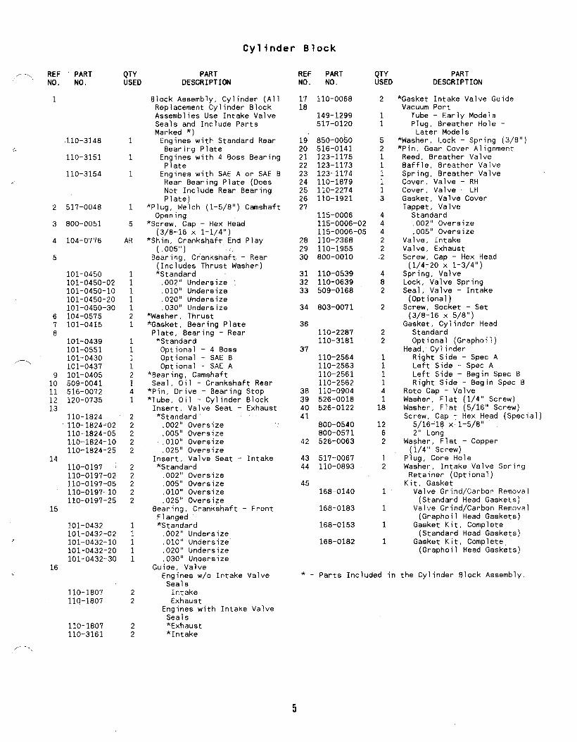
Carburetor (With Knte ra.1 Fuel Pump)( 1~“2 -0650 ):
,.9.
Components
------- “o
.-/’
1’
22
Y-W I /“21
17
I ,/- ‘r\,9 ~ /1
,,.-.,,
8
16
,( .,,
..
..
\ ’26 \t5
618
16
P.
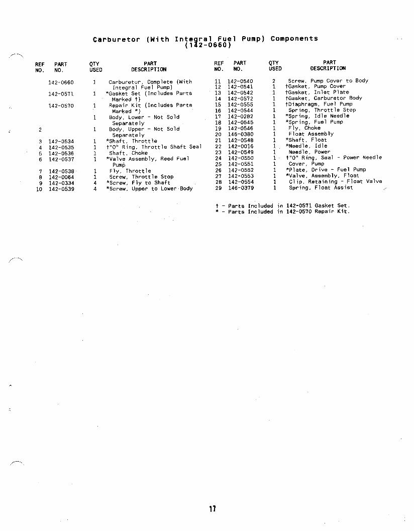
Carburetor (With
REF PART QTY PARTNO. NO. USED DESCRIPTION
2
3456
78
1:
142-0534142-0535142-0536142-0537
142-0538142-0064142-0334142-0539
142-0660 1
142-0571 1
142-0570 1
1
1
1111
;44
Carburetor, CompleteIntegral Fuel Pump)
*Gasket Set (IncludesMarked t)
Repair Kit (IncludesMarked *)
Integral Fuel Pump) Components(142-0660)
(With
Parts
Parts
Body, Lower - Not SoldSeparately
Body, Upper - Not SoldSeparately
*Shaft, Throttlet“O” Ring, Throttle Shaft SealShaft, Choke*Valve Assembly, Reed Fuel
PumpFly, ThrottleScrew, Throttle Stop*Screw, Fly to Shaft*Screw, Upper to Lower Body
REF PARTNO. NO.
11 142-054012 142-054113 142-054214 142-057215 142-055516 142-054417 142-028218 142-054519 142-054620 146-038021 142-054822 142-001623 142-054924 142-055025 142-055126 142-055227 142-055328 142-055429 146-0379
QTY PARTUSED DESCRIPTION
Screw, Pump Cover to BodytGasket, Pump CovertGasket, Inlet PlatetGasket, Carburetor Body+Diaphragm, Fuel PumpSpring, Throttle Stop
*Spring, Idle Needle*Spring, Fuel PumpFly, ChokeFloat Assembly
*Shaft, Float*Needle, IdleNeedle, Powert“O” Ring, Seal - Power NeedleCover, Pump*Plate, Drive - Fuel Pump*Valve, Assembly, FloatClip, Retaining - Float ValveSpring, Float Assist ....
t - Parts Included in 142-0571 Gasket Set.* - parts Included in 142-0570 Repair Kit.
/’-.

Air Housing
8I
I
,.-, :.,
REF PARTNO. NO.
1134-4430134-4400
2 815-0261
3 134-4371
A
134-3400
134--3518
1.
QTY PART REF PART QTYUSED DESCRIPTION NO. NO. USED
Housing, Blower 5 815-0290 41 Sets Without Oil Filter1 Sets With Oil Filter 6 526-0021 43 Screw, Cap - Hex Head 7 134-3582 1
(1/4-20 X 7/16”)1 Housing, Cylinder Air - Left 8 134-3583 1
SideHousing, Cylinder Air (RightSide)
1 Use Sets without Oil Filter- Free Flo
1 Use Sets with Oil Filter- Free Flo
.
18
/ -..
PARTDESCRIPTION
Screw, Cap - Hex Head(1/4-20 X 5/8”)
Washer, Flat (1/4” Screw)Baffle, Cylinder Head -Right Side
Baffle, Cylinder Head -Left S$de
.
,,--<,
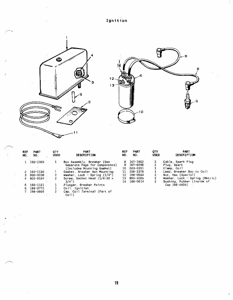
Ignition
1I
REF PARTNO. NO.
1 160-1303
2 160-11503 850-00384 802-0034
5 160-11516 166-07727 166-0604
QTY PARTUSED DESCRIPTION
1 Box Assembly, Breaker (SeeSeparate Page for Components)(Includes Mounting Gasket)
1 Gasket, Breaker Box Mounting2 Washer, Lock - Spring (1/4”)2 Screw, Socket Head (1/4-20 x
3/4”)1 Plunger, 8reaker Points1 Coil, Ignition2 Cap, Coil Terminal (Part of
Coil)
REF PART QTY PARTNO. NO. USED DESCRIPTION
8 167-1602 2 Cable, Spark Plug9 167-0298 2 Plug, Spark10 503-0311 Clamp, Coil11 336-2378 : Lead, Breaker Box to12 166-0554 2 Nut, Hex [Soecial)
Coil
13 850-2005 2 Washer, Lock - Sp~ing (Metric)14 166-0614 2 Bushing, Rubber (Inside of
Cap 166-0604)
19
.
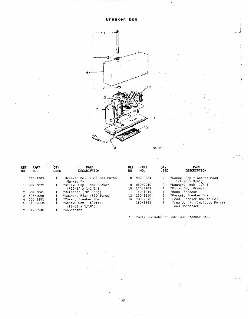
Breaker B-ox
REF PARTNo. No.
160-1303
1 802-0022
2 509-00653 526-00084 160-12855 815-0358
7 312-0246
IrI3 ,/.-.
11
I
,-,
?4 ES-1217
,,.-..,
REF PART QTY PARTNO. NO.. USED DESCRIPTION
Parts 8 802-0034 2 *Screw, Cap - Socket(1/4-20 X ‘3/4”)
Head
QTY PARTUSED DESCRIPTION
1 Breaker Box (IncludesMarked *) ‘
1 *Screw, Cap - Hex Socket 9 850-0040 2 *Washer, Lock” (1)4”)(#10-24 X 1-1/2”) 10 160-1183 1 *Point Set, 8reaker
1 *Retainer (“O” Ritig) 11 160-12.19 1 *8ase, Breaker1 *Washer, Flat (#10 Screw) 12 160-1150 1 *Gasket, 8reaker Box1 *Cover, Breaker Box 14 336-2378 11
Lead, Breaker Box to Coil*Screw, Cap - Slotted 160-1311 1 Tune Up Kit (Includes Points
(#8-32 x’5j16”)1
and Condenser)*Condenser
* - Parts Included in 160-1303 Breaker Box.
20

Starter Motor
/14
2“8
16
REF PARTNO. NO.
1 191-11712 815-0570
56789
1213
;21617
307-1031####
191:1156191-1220850-0040191-1219191-1038191--1221
#
23242’5;6
QTY PARTUSED DESCRIPTION
12
1111
21114
Starting Motor, CompleteScrew, Cap - Hex Washer Head(5/16-18 X l“)
Solenoid, Start - RelayxCover, DustxNut, StopxWasher, FlatxSpring, Anti-DriftxSpacer, Dust CoverDrive AssemblyScrew, Cap - Hex HeadWasher, Lock - Spring (1/4”)Cap Assembly, Drive EndWasher, Armature ThrustArmature
*+Spring
-\ \
/’///
REF PARTNO. NO.
1819 :20 #21 #22 #23 #24 #25 #26 #27 191-1040
28 #191-1222
29 191-1359
QTY PARTUSED DESCRIPTION
1121111111
11
1
+Brush Holder+Screw and Lock Washer
*+Brush, Ground*+Stud and Brush Assembly, Input+Bushing, InsulationWasher, Insulation+Washer, Flat+Washer, Lock+NutCap Assembly, Commutator(Includes Parts Marked +)
HousingRepair Package (IncludesParts Marked *)
Dust Cover Assembly (IncludesParts Marked x) ~ -,
+ – parts Included in 191–1040 Cap Assembly.* - Parts Included in 191-1222 Repair Package.# - Not Sold Separately.x – Parts Included in 191-1359 Dust Cover Assembly.
21

OPTIONAL EQUIPMENT SECTION
F\
This sact+ati contains illustrated parts listing of factory installedoptions. for” these fndust~ial engines. Options may net be-applicableto all models: for field conversions additional parts are usuallyrequired. Optional parts listed in this section are in addition or inplace of those shown in the standard engine parts section.
I: :,
I
22

Option 1Flywheel Alternator - 20 ,Ampere (Phelon)
1
\\\
REF PART QTYNO. NO. USED
1 191-1276 1
2 332-2423 23 323-1257 25 815-0470 3
e’PART REF PART
DESCRIPTION NO. NO.QTYUSED
Stator (Includes Terminals 6 191-1748 1and Connector Bodies) 7 821-0007 1
Terminal, Stator LeadsKit, Body Terminal Connector 8 167-0188 1Screw, Machine - Hex Head – 9 332-2319 1Self Lock (#10-32 x 1-1/2”)
PARTDESCRIPTION
Regulator, VoltageScrew, Cap - Hex Washer Head(1/4-20 X 1/4”)
Clip, CableClamp, Wire – Alternator Leads
23
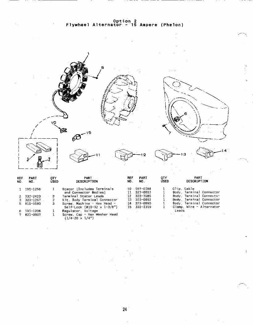
Op-ti.a.n 2‘Flywheel Alternator - -15 Ampere (P’helon)
;’
///
/
\--
REF PARTNO. NO.
1 191-1256
2 332-24233 323-12575 815-0593
6 191-12067 821-0007
1
323
11
5
PART REF PARTDESCRIPTION NO. NO.
Stator (Includes Terminals 10 167-0188and Connector Bodies) 11 323-0853
Terminal Stator Leads 12 323-1085Kit, Body Terminal Connector 13 323-0892Screw, Machine - Hex ’Head - 14 323-0890Self-Lock (#10-32 x 1-3/8’”) 15 332-2319
Regulator, VoltageScrew, Cap - Hex Washer Head(1/4-20 X 1/4”)
._,3 -14 ,_Q“N,. ,.
QTYUSED
1 Clip,1 8ody ,1 8ody ,
8ody ,: 8ody ,1 Clamp, Wire - Alternator
Leads
PARTDESCRIPTION
CableTerminal ConnectorTerminal ConnectorTerminal ConnectorTerminal Connector

Option 3Governor Control - Variable Speed
(Side Pull)
12.
REF PART~,,/ NO. NO.
1 150-12142 153-05143 150-17254 815-0359
5 815-0510
6 150-13987
150-1345150-1576
8 815-0436
QTYUSED
:
;
1
1
112
3 10
PARTDESCRIPTION
7
REF PARTNO. NO.
9 526-0021Spring, GovernorClamp, CableBracket, CableScrew, Tapping - Hex Head(#10-32 X 7/8”)
Screw, Tapping - Hex Head(#6-32 X 5/8”)
Spring, Idle SettingArm, Governor Control
Use With SwivelUse Without Swivel
Screw, Cap - Hex Washer Head(1/4-20 X 1/2”) 17 152-0155
10 150-126911 518-0406
12 518-0004
13 150-192414 516-005915 526-0006’16 815-0104
FS-1274
QTY PARTUSED DESCRIPTION
2 Washer, Flat (17/64” ID x3/4” OD X 1/16”)Bushing, Control Arm
; Clip, Retaining - Control Rodto Governor Shaft
1 Clip, Retaining - Control Rodto Carburetor
1 Rod, Governor Control1 Pin, Cotter1 Washer, Flat (#12 Screw)1 Screw, Machine - Fill ister
Head (#8-32 x 5/16”)1 Swivel, Cable Holding
25

Option 4., Governor Control - Variable Speed(Front Pull)
7
REF PARTNt). NO.
1 150-18102 150-13663 815-0439
4 150--13695 862-00016 150-13677 815-0181
8 800-0004
QTYUSED
113
i12
1
PARTDESCRIPTION
Bracket, Governor Contro~Link, Governor ControlScrew, Cap - Hex Head Locking(#8 X 1/2”)
Spring, GovernorNut, Hex (1/4-20)Adapter, Governor ArmScrew, Cap - Hex Head W/ET(#10-32 X 1/2”)
Screw, Cap - Hex Head(1/4-20 X 5/8”)
REF PARTNO. NO.
9 526-002110 150-126911 850-004012 815-0104
13 152-0155~~ 5~6-ooo615 516-005916 518-0176
QTYUSED
:
;
1111
,.
..
PARTDESCRIPTION
Washer, Flat (1/4” Screw)..-
Bushing, Governor ControlWasher, Lock - Spring (1/4”)Screw, Machine - FillisterHead (#8-32 x 5/16”)
Swivel, Cable - ThrottleWasher, Flat (#12 Screw)Pin, CotterClip, Cable - Throttle
.
!.
,--,
26

REF PARTNO. NO.
1 142-0661
P.
2 145-04383 850-00404 800-0023
5 503-0731
0 tion 5Fue Y System
1
QTY PART REF PART QTYUSED DESCRIPTION NO. NO. USED
PARTDESCRIPTION
1
122
3
Carburetor Assembly - Gasoline 6 503-0664 1 Hose, Fuel (1/4” ID x 11” Lg)(See Separate page for 7 149-2187-01 1 Pump, Fuel (Includes PartsComponents) (InciudesMounting Gasket) (IncludesParts Marked +)
Gasket, Carburetor MountingWasher, Lock - Spring (1/4”)Screw, Cap - Hex Head(1/4-20 X 1-3/8”)
+Clamp, Hose (7/16”)
Marked *)8 815-0555 2 Screw, Tapping - Pan Head
(10-24 X 5/8”)9 149-1321 +Cap, Fuel Outlet
10 149-1299 ; Tube, Vacuum Port11 503-0663 1 Line, Impulse12 503-0731 1 Clamp, Wire (1/2”)
+ - parts Included in 142–0661 carburetor AssemblyKit.
/----
27
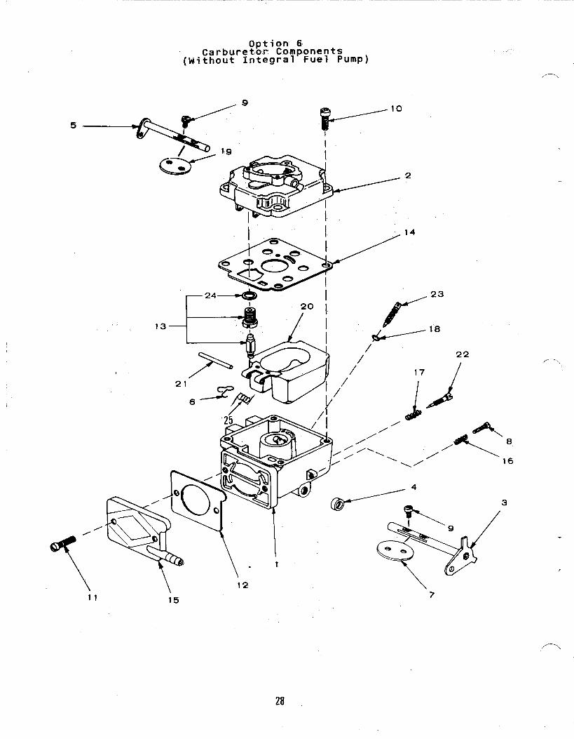
Option 6Carburetor Components ,..
(Without Integral Fuel Pump)
,—.
13
10
L-— ““
,,—,
11 15.6
28
REF PARTNO. NO.
142-0661
142-0592
142-0591
1
2..
3 142-05344 142-0535
5 142-05366 142-0554‘1 142-05388 142-00649 142-0334
;TYD
1
1
1
1
1
11
1
;14
Carbure!~~18;m$onents(Without Integral Fuel Pump)
PARTDESCRIPTION
Carburetor, Gasoline (IncludesMounting Gasket)Repair Kit (Includes PartsMarked t)
Gasket Kit (Includes PartsMarked *)Body, Lower (Not SoldSeparately)
Body, Upper (Not SoldSeparately)
tShaft, Throttle*O-Ring, Packing - Throttle
ShaftShaft, ChokeClip, Retaining - Float ValveFly, ThrottleScrew, Throttle Stop
tScrew, Fly to Shaft
REF PARTNO. NO.
10 142-053911 142-053912 142-055913 142-055314 142-057215 149-1983
16 142-054417 142-028218 142-055019 142-054620 146-038021 142-054822 142-001623 142-054924 142-052325 146-0379
QTYUSED
421111
11111“11
1
t - Parts Included in* – parts Included in
PARTDESCRIPTION
Screw, Upper to Lower BodyScrew, Inlet Plate*Gasket, Inlet PlatetValve Assembly, Float*Gasket, Carburetor BodyPlate, Inlet (Includes Capand Clamp)
Spring, Throttle StoptSpring, Idle Needle*O-Ring, Packing - Power NeedleFly, ChokeFloat AesemblytShaft, FloattNeedle, IdleNeedle Assembly, Power
*Gasket, Float Valve SeatSpring, Float Assist
142-0592 Repair Kit.142-0591 Gasket Kit.
,-.
29
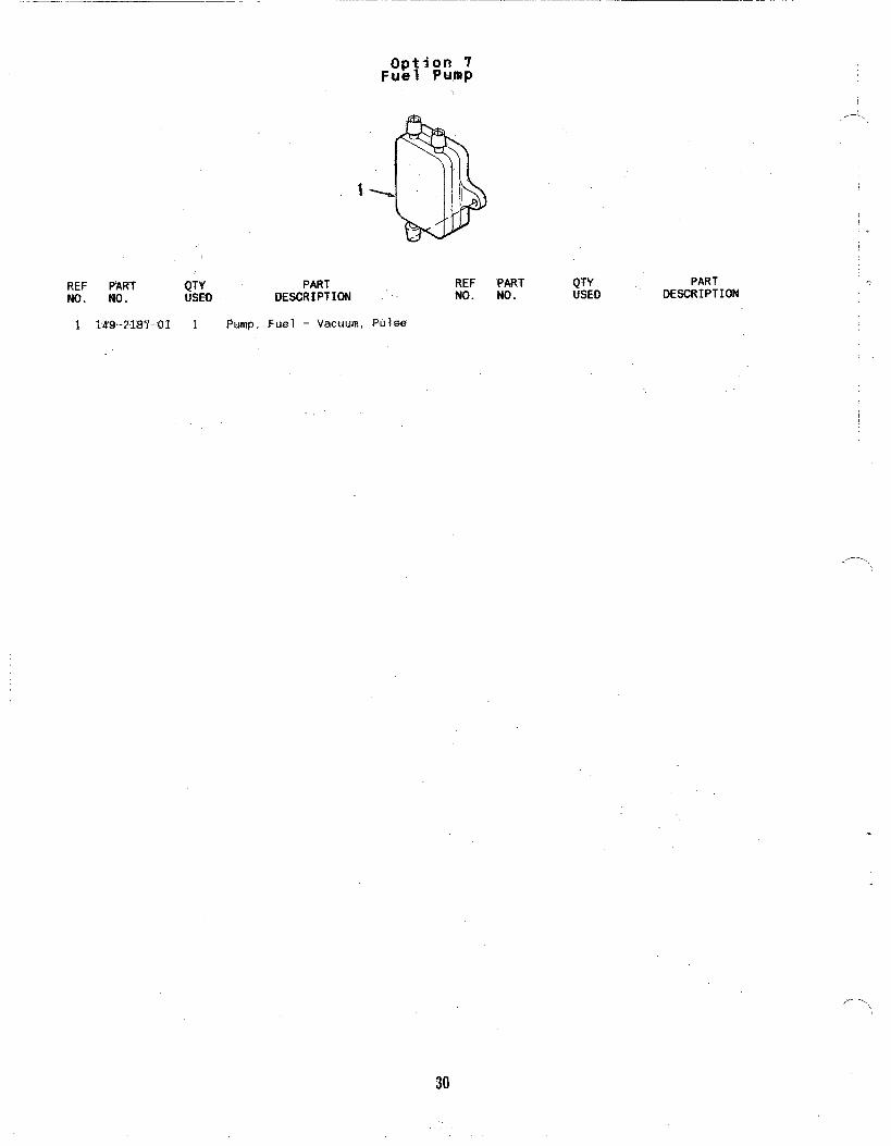
Option 7Fuel PU,mP
1
REF PART QTY PARTNo. MD. USED DESCRIPTION
1 149-2187-01 1 .Pump. Fuel - Vacuum, Ptilse
REF PARTNO. NO.
QTY PARTUSED OEWRIPTION
/-,
.
,-,,
30
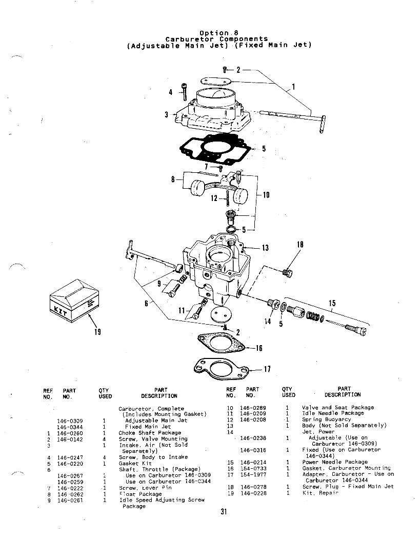
Option 8Carburetor Components
(Adjustable Main Jet) (Fixed Main Jet)
4
8%’110H-J
f-.
i9
REF PART.N07 NO.
PARTDESCRIPTION
QTY PART REF PARTUSED DESCRIPTION NO. NO.
QTYUSED
Valve and Seat PackageIdle Needle PackageSpring BuoyancyBody (Not Sold Separately)Jet, Power
Adjustable (Use onCarburetor 146-0309)
Fixed (Use on Carburetor146-0344)
Power Needle PackageGasket, Carburetor MountingAdapter, Carburetor - Use onCarburetor 146-0344
Screw, Plug - Fixed Main JetKit, Repair
Carburetor, Complete(Includes Mounting Gasket)Adjustable Main JetFixed Main Jet
Choke Shaft PackageScrew, Valve MountingIntake, Air (Not SoldSeparately)
Screw, Body to IntakeGasket KitShaft, Throttle (Package)
Use on Carburetor 146-0309Use on Carburetor 146-0344
Screw, Lever PinFloat PackageIdle Speed Adjusting ScrewPackage
1011121314
146-0289146-0209146-0208..
146-0309146-0344
1 146-02602 146-01423
11141
146-0238 1
146-0316 1
41
4 146-02475 146-0220 15
1617
146-0214154-0733154-1977
111/’-\
6146-0267146-0259
11
1819
146-0278146-0228
11
7 146-02228 146-02629 146-0261
11
31
.
REFNO.
PARTNO.
QTY PART REF PART QTY PARTUSED DESCRIPTION NO. NO. USED DESCRIPTION
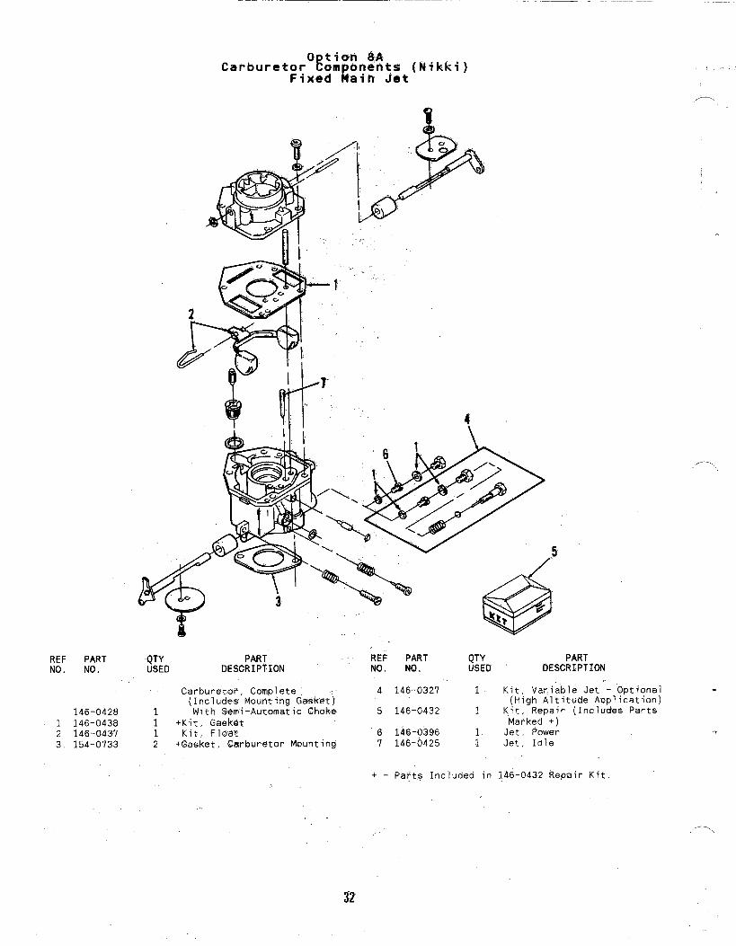
Carburet~r, Com~lete(Includes Mounting Gasket)
146-0428 1 With Semi-Automatic Choke1 146-0438 1 +Kit, Gasket2 146-0437 1 Kit, FIoat3 154-0733 2 +Gasket, Carburetor Mounting
4 146-0327 1 Kit, Variable Jet - Optional(High Altitude Application)
5 146-0432 1 Kit, Repair (Includes PartsMarked +)
6 146-0396 1 Jet, Power7 146-0425 1 Jet , Idle
+ - parts Included in 146-0432 Repair Kit,
,...,
.
. “-...,
32

10a
1-
,/-
6f11-
REF PARTNO. NO.
159-05971 159-0981-.2 159-05963 159-05954 134-0599
.. 5 501-00086 159-0020
QTYUSED
11221
;
Option 9Fuel Tank (Side Mounted)
I I
I II III
II
I II IIII
PARTDESCRIPTION
.1
Kit, Fuel Tank – CompleteTank, Fuel (Less Cap)Strap, Fuel TankBracket, Fuel TankClip, Fuel LineLine, FuelCap, Fuel Tank
REF PART QTY PARTNO. NO. USED DESCRIPTION
7 504-0013 1 Valve, Shut-off8 505-0057 Plug, Tank Drain9 502-0020 i Elbow, Carburetor Inlet10 813-0108 2 Screw, Machine - Round Head
(#10-32 X 1-1/2”)11 870-0053 2 Nut, Hex (#10-32)
33

con t ho 1
2’5
REF PARTNO. NO.
1 152-01982 526-00153 152-00414 800-0005
5 870-00656 301-40417 821-0009
8 308-03859 302-006010 193-000511 502-001712
13
14
QTYUSED
1221
112
11111
1
1
PARTDESCRIPTION
Lever, Throttle ControlWasher, Flat (1/4” Screw)Washer., Tension - CupScrew, Cap - Hex Head(1/4-20 X 3/4”)
Nut, Lock - Hex (1/4-20)Panel , ControlScrew, Lock - Hex(1/4-20 X 5/16”)
Switch. and Key, IgnitionAmmeter, DC (20-0-20)Gauge, Oil PressureConnector, Inverted ‘FemaleLead, Electrical - #16 Wire,26” Lg,Lead, Electrical - Switch toCoil - #16 Wire, 13” Lg.Lead, Electrical - Switch toAmmeter - #16 Wire, 7“ Lg.
REF PARTNO. NO.
15 332-0942.16 870-013.1’17 815-0199
18 153-009719 501-000420 502-002021 150-154422 ‘81-5-019423 150-0098’24 150-0096.25 150-0621
26 308-0490?7 3“32-032528 332-14082.9 332-199330 526-0016
QTY PARTUSED DESCRIPTION
1 Tie, Cable2 Nut, Hex (10-32)2 Screw, Machine - Fill ister
Head (10-32 x 5/16”)1 Cable, Choke1 Line, Oil - Flexible1 Elbow, Street (90”)1 Adapter, Governor Arm2 Screw, Tapping (10-32 x 3/8”)1. Spring, Governor1’ Stud, Speed Adjusting1 Nut, Special - Speed
Adjusting Stud1 Key, Ignition Switch1 Terminal, Ring1 Terminal, Faston1 Terminal, Receptacle1 Washer, Flat (1/4)’ Screw)
.
/-.. .
34

Option 10AControl (Engine)
Q,’
22
8
,-\ REF PART QTYNo. No. USED
1 301-5065 12 153-0097 13 193-0005 14 302-0060 15 308-0385 16 152-0224 17 338-1219 18 502-0051 19 800-0005 1
10 526-0016 111 152-0041 112 526-0015 213 870-0065 1
PARTDESCRIPTION
Panel, ControlCable, ChokeGauge, Oil PressureAmmeter (20-0-20)Switch, IgnitionLever, Throttle ControlHarness, WiringCoupling, FemaleScrew, Cap - Hex Head(1/4-20 X 3/4”)
Washer, Flat (1/4” Screw)Washer, Tension - CupWasher, Flat (1/4” Screw)Nut, Hex - Self Locking(1/4-20)
REF PARTNO. NO.
14 815-0199
15 870-013116 150-1749’17 815-0181
18 150-121419 152-017720 150-062121 502-000522 517-000923 308-049024 501-000925 502-0065
QTYUSED
2
211
1111AR111
PARTDESCRIPTION
Straw, Machine – FillisterHead (#10-32 x 5/16”)
Nut, Hex with ET (#10-32)Extension, Governor ArmScrew, Tapping - Hex Headwith ET (#10–32 x 1/2”)
Spring, GovernorStud, Speed AdjustingNut, Speed Adjusting StudElbow, Inverted - Female (90”)Plug, Dot 8uttonKey, Ignition SwitchLine, Oil - Flexible (36” Lg)Elbow, Inverted - Male (45”)
35

15
REF PART QTYNO. NO. USED
1 122-0369 12 505-0791 13 505-0776 14 122-0375 15 526-0065 2
6800-0031 2
800-0030 2
7 801-0047 1
/
.4I!
,.
-7
I2 ,.
..PART REF PART QTY PART
DESCRIPTION NO. NO. USED D~SCRIPTION
+Adapter, Remote Oil FilterNipple, Pipe (1/4 x 7“)Nipple, Pipe (1/4 x 6“)Gasket, AdapterWasher, Flat - Copper(5/16” Screw)
Screw, Cap - Hex HeadPrior to 6/86 (5/16-18 x1-1/2”)
Begin 6/86 (5/16-18 x1-1/4”)
+Screw. Cao - Hex Head“(3/8L24 x 5/8”)
8 526-0066 1 +Washer, Flat - Copper(3/8” Screw)
9 120-0140 1 +Spring, By--Pass Valve10 120-0398 1 +Valve, By-Pass12 505-0057 1 +Plug, Pipe - Square Head13 508-0184 1 Grommet, Air Seal14 122-0473 1 Adapter Assembly, Remote Oil
Filter (Includes Par&sMarked +)
15 122-0476 1 Base Assembly, Remote OilFilter
+ - parts Included in 122-0473 Adapter Assembly.
b NOTE; Hoses vary with each installation.Purchase locally, hoses with a minimumpressure rating of 150 PSI (1035 kPa).
36
, ..../ .
,.--.,,

18
,,, =,
Option 12starter Motor Components - Solenoid Shift
1
REFNO.
3
20
123456
78
1:
Ir7 —d
PART QTYNO. USED
191-0915 1191-0965 1191-0966 1191-0967 1191-0968 2191-0969 2191-0970 1
191-0971 1191-0972191-0973 1191-0974 1
PARTDESCRIPTION
Motor, StartingLever AssemblySpring SetSwitch AssemblySpring, BushBolt, ThroughBracket Assembly, Front(Includes Bearing)
Bearing FrontStopper Set, PinionClutch AssemblyArmature
REF PARTNO. NO.
11 191-097512 191-0976
13 191-097714 191-097815 191-0979
16 191-098017 191-098118 191-098219 -191-107620 307-0845
QTY PARTUSED DESCRIPTION
1 Washer Set1 Yoke Assembly (Includes Brush
and Screws)4 Screw, Flat Head Machine1 Brush (+)1 Rear Bracket Assembly
(Includes Bearing and Brush)1 8earing, Rear1 Brush (-)1 Screw Set1 Seal, Starter Air1 Relay, Start Solenoid
,.
/-,
37

Option 12AStart Motor Components {Heavy -Duty)
5
.-,
.
21;2
13
I /.14 146
‘\
/’//.—2’9
2’8
,,, , 23242’5~6
REF PART QTY PARTNO. NO. USED DESCRIPTION
REF PARTNO. NO.
QTY PARTUSED DFSGRXPTION
20 ‘21 !22 s
12
5678910
191-’0933815-0570
12
Motor, Starter (Cnmplete)Screw, Cap - Hex Washer Head(’5/16-T8 X l“)
Relay, Start SolenoidxCover, DustxNut, StopxWasher, Stop NutxSpring, Anti-driftxSpacer, Dust CoverDrive AssemblyScrew, Hex Cap - SpecialWasher, Lock (1/4”)Cap Assembly, Drive EndWasher, Armature Thrust”-Special
Armatu~et*Spring., ‘Brusht8rush ~HoldertScrew anti Loc.kwasher
211
+*Brush, Groundt*Stud and Brush Assembly, InputtBru,ehing, Insulation – Input
StudtWasher, ‘Insulation - Input
StudtWasher, ‘Flat - Input StudtWasher, Lock - Input StudtNut, Securing - Input StudCap Assembly, Commutator(Includes ’Parts Marked tj
Housing, Starter MotorRepair Kit, Brush, Spring andStud (Includes Parts Marked
307-10311
2425 :26 427 191-1040
1111
.111
1112
191-1036191-1048850-0040191-1037191-1038
12
28 5191-loal
11
211
1412
15
16171819
*)1 Oust Cover Assembly29 191-”1359 (Includes191-1039
s
:
Parts Marked x)
t - Included in the 191-1040 Cap Assembly.* - In~]uded in the 191–1041 8rush, SPrin9 and Stud
Kit,$ -Mot Sold Separately.x – Included in 191-1359 Dust Cover Assembly.
38
REF PARTNO. NO.
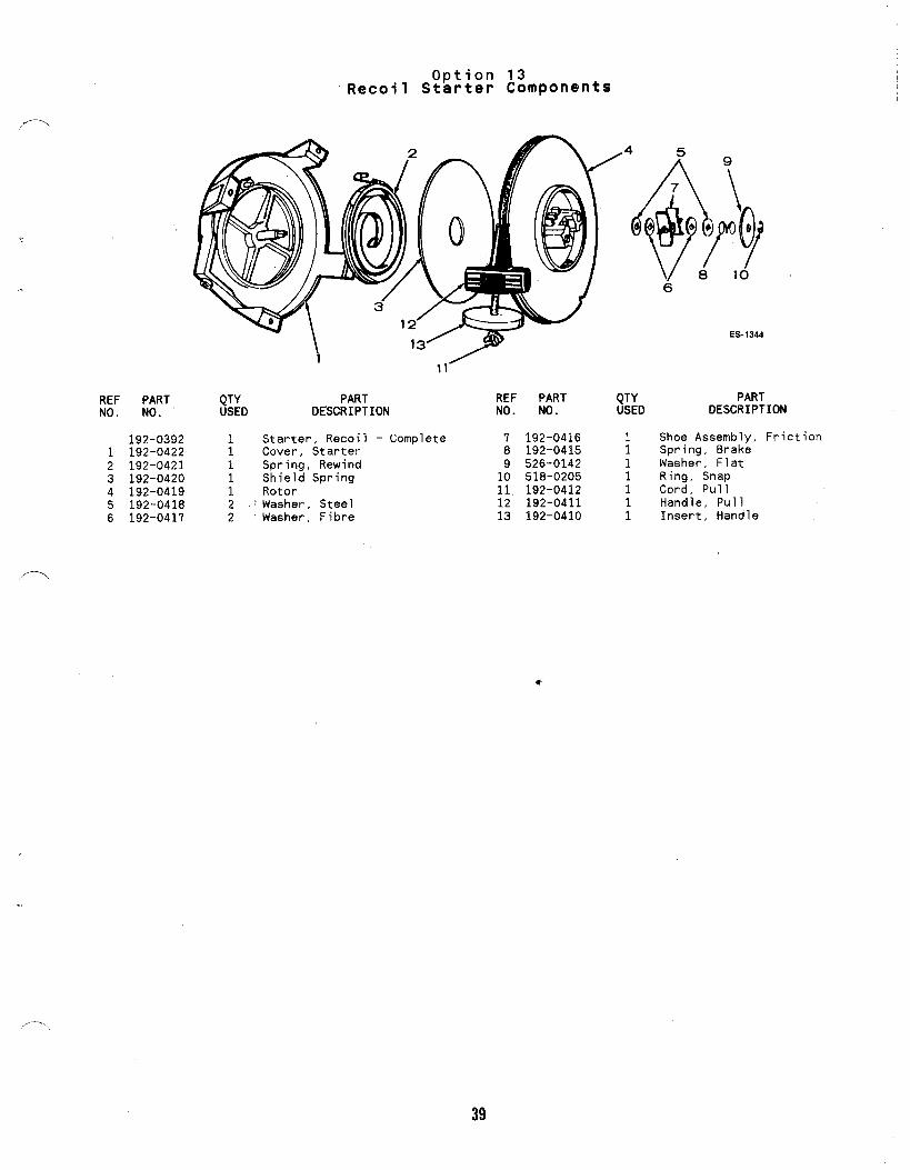
192-03921 192-04222 192-04213 192-04204 192-04195 192-04186 192-0417
Option 13Recoil Starter Components
QTY PARTUSED DESCRIPTION
1 Starter, Recoil - Complete1 Cover, Starter1 Spring, Rewind
Shield Spring; Rotor2 ~Washer, Steel2 Washer, Fibre
REF PARTNO. NO.
7 192-04168 192-04159 526-014210 518-020511, 192-041212 192-041113 192-0410
QTYUSED
1111111
6
ES-1344
PARTDESCRIPTION
Shoe Assembly, FrictionSpring, BrakeWasher, FlatRing, SnapCord, PullHandle, PullInsert, Handle
39

.—
Option 14Fuel Pump (Electric)
REF PART QTY PARTNO. NO. USED DESCRIPTION
149-1828 1 Pump, Fuel
[

0 tion 15YOil Fi ter (Spin-On)
!,,.
REF PART QTYNO., NO. USED
1 122-0320 12 526-0065 2
3 800-0028 2
4 505-0057 1
‘PARTDESCRIPTION
Adapter, Oil FilterWasher, Flat - Copper(5/16” Screw)
Screw, Cap - Hex Head(5/16-18 X 1“)
Plug, Pipe (1/8”)
REF PART QTYNO. NO. USED
5. 122-06456 122-0347 i7 122-0360 18 815-0194 2
9 122-0321 ~~1
PARTDESCRIPTION
Filter, OilSeal, Air - Filter to HousingDrain, Oil FilterScrew, Cap - Hex Head w/ET(#10-32 X 3/8”)
Gasket, Oil Filter Adapter
41

--
Option 16Ignition Breaker Box (Side Adjustable) . ...
4*
REF PARTNO. ND.
160-1.158
1 815-0358
2 160-11493 160-11484 802-0034
5 850-00386 815-0403
7 850-0025
a 6-7 11
9-1o
l!l- 13
,.
QTY PART REF PART QTY PARTUSED DESCRIPTION NO. NO. USED DESCRIPTION
1 Box Assembly, Breaker 8 312-0069 1 *Condenser, Ignition(Includes Parts Marked *) 9 .870-0221 1 *Nut, Hex with External Tooth
2 *Screw, Tapping - Hex Head, Lockwashet” (#8-32)Slotted (#8-32 x 5/16”) 10 815-0405 1 *Screw, Machine - Pan Head,
1 *Cover, Breaker Box “. Cross-Recessed (#8-32 x 1/2”)1 *Gasket, Cover 11 160-1154 1 *Point Set, 8reaker2 *Screw, Cap - Socket Head 12 160-1150 1 *Gasket
(1/4-20 X 3/4”) 13 160-1151 1 Plunger, 8reaker Points2 *Washer, Lock - Spring (1/4”) 14 336-2378 11
Lead, Breaker Box to Coil*screw, Tapping - Pan Head 160-1161 1 Tune-Up Kit (Includes Points
(#8-32 X 5/16”)1
and Condenser)*Washer, Lock - Spring (#8)
* T Parts Included. in 160-1158 Breaker Box A~sembly.,,
,— ,,
42

Option 17Support and Terminal Block Assembly
ES-14S1
/-. REF PARTNO. NO.
1140-1644
301-5936
2 812-0081
3 860-0008
QTY PARTUSED DESCRIPTION :
Support, Air Cleaner1 Units with Air Cleaner
Housing1 Units without Air Cleaner
Housing2 Screw, Machine - Round Head
(#8-32 X 5/8”)2 Nut, Hex (#8-32)
REF PARTNO. NO.
4 853-00055 332-05376 332-22087
336-4385
334-0028
QTY PARTUSED DESCRIPTION ,.
2 Washer, Lock - ET (#8)1 Block Terminal (,4 Place)1 Strip, Marker
Lead Assembly1 Alternator (Use Bulk #16
Wire)1 Ignition
43

..
REF PARTNO. NO.
160-1306
1 167-15952 167-02983 160-13054
526-0015526-0184
To6
QTYUSED
1
221
22
@
.’
9
e
PART R’EF PARTDESCRIPTION NO. NO.
Stator Assembly (Includes ~ 160-0749Parts Marked *) .6 l~qk~~ss
Cable, Spark PIug R.H. 7 815-0259Spark Plug 8 508-0095*Coil, Magneto Stator 9 336-8466Washer, Flat - Stator
1/4” Screw1$/64 ID X 5/8 ~0 X,1345” Thk)
3
QTYUSED
,,7.,
PARTDESCRIPTION
1 *Pole Shoe, Stator - Magneto-4 Clip, Spark Plug Cable2 Screw, Hex Cap2 Grommet, ‘Rubber1 Lead, Magneto to Ignition
Breaker
* – parts Included in the 160–1306 Stator A$sembly
44

Option 19Remote Air Cleaner Adapter
REF PART QTYNO. NO. USED
PARTDESCRIPTION
140-1915 1 Kit, Remote Air CleanerAdapter (Includes PartsMarked *)
1 509-0145 1 Seal, O-Ring2 850-0030 3 *Washer, Lock - Spring (#10)3 123-1417 1 *Filter, Breather Tube4 123-1539 1 *Tube, Crankcase Breather5 503-0107 1 Clamp, Breather Tube
(3/
REF PARTNO. NO.
- 6 140-17147 813-0106
8 140-14289 503-0274
10 503-017111 517-0151
9
.-
FS-1131R
QTY PARTUSED DESCRIPTION
1 *Adapter, Carburetor Air Intake3 *Screw, Machine - Round Head
(#10-32 X 1-1/8’1)1 *Elbow, Air Intake1 *C]amp, Hose – Air Intake1 *Clamp, Hose1 *Pluq, Dot Button -
Ho~sing Air Hole
* - Parts Included in 140–1915 Remote AirAdapter Kit.
Blower
Cleaner
45
1
REF PARTNO. NO.
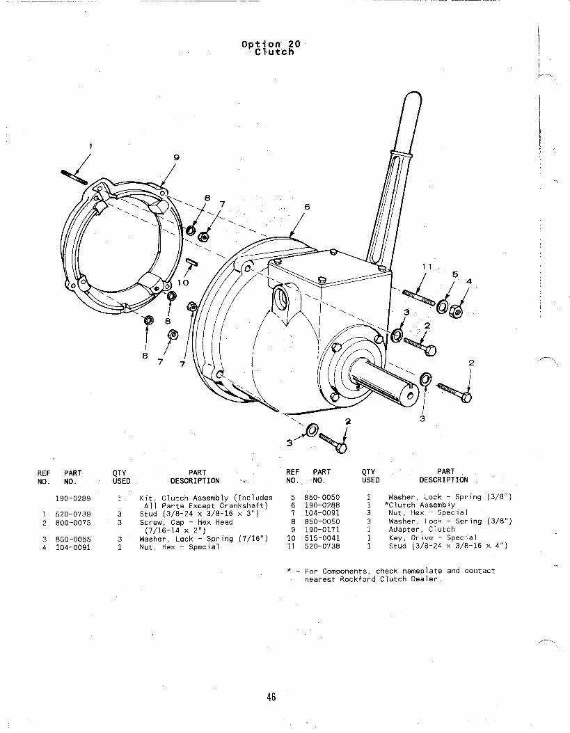
190-0289
1 520-07392 800-0075
3 850-00554 104-0091
1 @/ill// /
QTY PART REFUSED DESCRIPTION :. NO.
\ 2 3\-
1 Kit, Clutch Assembly (Includes 5All Parts Except Crankshaft) 6
3 Stud (3/8-24 X 3/8-16 X 3“) 73 Screw, Cap - Hex Head 8
(7/16-14 X 2“) 93 Washer, Lock - Spring (7/16”)1 Nut, Hex - Special i:
w
PARTNO.
850-0050190-0288104-0091850-0050190-0171515-0041520-0738
QTY PARTUSEO DESCRIPTION
I
1 Washer, Lock - Spring (3/8”)1 *Clutch Assembly3 Nut, Hex - Special3 Washer, Lock - Spring (3/8”)1 Adapter, Clutch
Key, Ot-ive - Special; Stud (3/8-24 X 3/8-16 X 4“)
*. For Components, check nameplate and contact.
nearest Rockford Clutch Dealer.
,,.-. \
46

REF PARTNO. NO.
.-1 526-01402 153-05233 153-05004 153-05245 821-0002
6 815-04807 854-0010
QTYUSED
11
Option 21Choke Control (Front Pull)
9
PARTDESCRIPTION
Washer, Flat (#10 Screw)Lever, ChokeLink, ChokeBracket, Choke CableScrew, Cap - Hex Washer Head(#10-32 X 1/4”)
Screw, Shoulder (#10-32 x .34”)Washer, Lock - IT (#10)
‘ ,
FS-1131R
REF PART QTY PARTNO.. NO. USED DESCRIPTION
8 152-0155 1 Swivel, Choke Lever9 815-0693 .1 Screw, Machine - Hex Head
(#8-32 X .31”)10 516-0059 Pin, Cotter11 815-0359 ; Screw, Tapping - Slotted Hex
Washer Head (#10-32 x 7/8”)12 153-0514 1 Clip, Choke Cable
/’-”.
47

~-
Miscellaneous Options ~
1?
—16
19’
REF PARTNO. NO.
1 134-32132 815-0378
3 140-1218
4309-0237
309-0510
5 193-0108
6 403-10217 122-04068 332-01529 502-017510 502--0020
QTYUSED
14
1
1
1
1
21112
PARTDESCRIPTION
Guard, Flywheel - StationaryScrew, Tapping - Hex Head(#14 x 1/2”)
WrapDer, Filter Element - DryType
Switch. Low Oil PressureClose at 8-10 PSI atLowering Pressure
Open at 4.5-7.5 PSI onIncreasing Pressure
Sender’, Electric Oil PressureGauge
Bracket, LiftingFilter, Oil (With Hex Nut)Terminal., RingAdapter,. PipeElbow, Street - 90”
REF- PARTNO. NO.
134-3527134’-4134
12
13 502-005314 140-1169
15 140-1747
16 140-1750
17 332-140818 332-127919 159-1150
QTYUSED
111
11
1
1
[I
,/—\
PARTDESCRIPTION
Guard, Flywheel - Stationary(Wire Type)Use without PTOUse with PTO
Lead Assembly, LCIWOilPressure Switch - #16 Wire,12[’ Lg (2)
Elbow, Street - 45’Tube, Air Intake with OebrisLip
Cover, Air Cleaner - MoistureProaf
Knob., Air Cleaner - MoistureProofTerminal, ReceptacleTermina’1, SpadeTank, Fuel - Plastic (3.5Gallon Capacity) e
48

,m.
Miscellaneous Exhaust Options
REF PART QTYNO. NO. USED
1 155-1570 22 155-1692 14 154-1958 2
5 154-1725 2. 6
155-1697 2155-1693 2
7. 155-1256 ‘2
155-1257 28
154-1986154-1669 ;154-1986154-1669 i
R’,
.,~r
/’2“A ,13
..,
NOTE:Variousexhaust optionsareused onB43M-GAO16 industrialengines. Select according to illustration.
PARTDESCRIPTION
Muffler, ExhaustMuffler, ExhaustAdapter, Exhaust (FlangeType )
“Gasket, Exhaust AdapterMuffler, Exhaust- - Raygu’n”
With Spark ArrestorWithout Spark Arrestor
Clamp, Muffler1-1/4”1-3)8”
Manifold, Exhaust - CrossoverLeft Rear Outlet -Left Front OutletRight Front OutletRight Rear Outlet
REF “, PART : ‘QTYNO. NO. .U~ED,,
9155-1703155-1704 .:
10 155-1848 ;111
:505-0775 - .2505-0755 ‘. ‘2
12 155-1722 ‘ 113 155-1723 114 154-2128 1
15 154-2129 1
17 800-0026 4.
18 850-0045 4
PART,’ DESCRIPTION
Pi~~itExhaust (90”)
Right ~Muffler, Crossover ““Nipple, Half - Exhaust
1“ X 1-13/16”~,, x ~ ,1
Muffler ‘- RHMuffler - LHAdapter, Exhaust – Right(1-1/4” 00 Outlet)
Adapter, Exhaust - Left(lL1/4° OD Outlet)
Screw, Cap - Hex Head(5/16-18” X 3/4”)
Washer, Lock - Spring 5/16”
49

Part No. Page
332-2748 24336-237% 22336-2378 23336-96’79 17337-2229 28337-2311 11337-2311 31338-1080 42338-108T 42338-1082 42338-1931’ 41338-1932 41338-2031 41357-0030 41359-0034 42370-4027 33402-0549 11402-0597 11U03-15.23 5403-1523 31403-2218 11.40-3-2280 11:403--2280. 3-6405-3332 36405-3333 364’05-3334 36405-3335 36405-3405 36405-3453 36405-3611 36405-3612 36406-0566 36406-0567 36406-0568 36501-0497 17502-0002 15502-0054 17502-0313 15502-0871 15502-0923 17502-0927-01 17502-0928-01 17502-0929-01 17502-0932-01 .17502-0933-01 17502-0935 17502-0965-01 17503-0183 15503-0183 17503-1133’ 15
Part No.
503-1133503-1190503-1252503-1336503-1337503-1345503-1351503-1365504-0150505-0110505-0266505-0274508-0008508-0071508-0251508-0253508-0253509-0008509-004050.9-0041509-0096509”-0168509-0196509-0210510-0013510-0014510-0015510-0099515-0001515-0001515-0227516-0072516-0130516-0141517-0048517-0067517-0129517-0223‘“518-0006518-0014518-0311518-0387518-0450518-0452518-0459518-0466525-0305526-0002526-0003526-0008
.
Numerical Index
Page
171715151515151717111117363641394113135
115
285
13138
39~
9~
.513557
31152197
15154315154-3151717
Part No.
526-0017525-0018526-0018526-0018526-0.018526-0’018526-0018526-0030526-0063526-0065526-0065526-0066526-0066526-0122526-0130526-0240526-0324526-0325526:1518800-0002800-0’004800-0005800-0007800-0007800-0010800-0017800-00178“00-0026800-00268Q0-0028800-003U800’-0033800-0033-80Q-Q036800-0046800-0048800-0051800-0052800-0052800-0058‘800-0540800-0545800-0571800-0572800-0730800-0730801-0049801-0050802-0034802-0034
52
Page
95
1517283339367
1273575
35111111363635337
335151733“35123315.17335
313924391151355
333577
2223-
Part No,
802-1038803-0071812-0061812-0061812-0062815-0046815-0176815-0181815-0194815-01948?5-0194815-0194815-0235815-0261815-0261815-0261815-0261815-0261
/. .,Page
‘,,
395
274141131739
.
12-283941281517222731
815-0261 33815-0,261 41815-0290 ’28 :815-0337 28815-0337 39815-0340 27 +>.815-0358 23815-0359 39
d
815-0359 41815-Q370 17815-0370 22815-0370 27815-0385 . 42815-0387 -41-815-0388 41815-0436 39815-0499 33815-0531 17815-0550 418T5-0570-’ 25815-0583 27815-0584 39 .;815-0587 . 15815-0587 17.815-0590 15 *
815-0590 17815-0591 15815-0591 . 17815-0592 15815-0610 15815-0610 28 -<<8-15-0647 17
2

Numerical Index
,.~~,Part No.
815-0657820-1077821-0005821-0009821-0009‘“~?-oolo.-821-0010821-0010821-0014821-0014821-0014821-0016821-0016821-0016821-0029821-0029821-0029821-0031821-0031821-0033850-0020850-0038850-0038,~850-0040850-0040850-0040850-0040850-0040850-0040850-0040850-0045850-0045850-0045850-0045850-0050850-0050850-0050850-0050850-0055850-2005856-0006856-0008856-0008856-0010860-0005862-0001862-0001862-0003
,— .> 862-0003862-0015
Page
1113171531113136113136511311133351136364122237
172425333536151733355
1124399
2215112831422433243915
Part No. Page Part No. Page Part No. Page
862-0015 17870-0131 21870-0196 27870-0221 17870-0257 36870-0302 7870-0328 13870-0421 15870-0433-03 28870-0437 36870-1183 27898-1193-03 28
53

-——- .—t ’
/-’.,
\\
..
.—— —. .— .
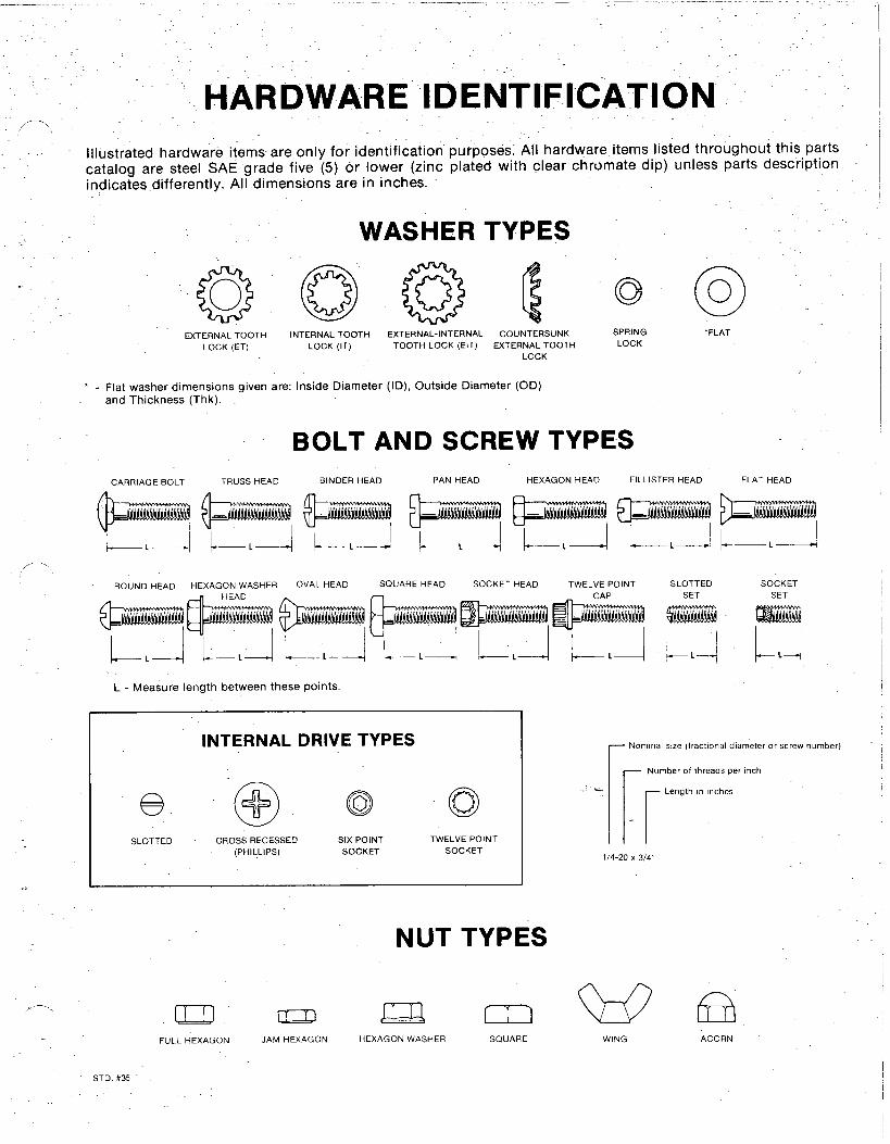
HARDWARE IDENTIFICATION,-.,
.. . Illustrated hardware items are only for identification purposes. All hardware items listed throughout this partscataloa are steel SAE grade five (5) or lower (zinc plated with clear chromate dip) unless parts description‘indica;es differently. Al~dimensionk “are in inches.
WASHER TYPES
..
@COUNTERSUNK SPRING ‘FLATEXTERNAL TOOTH
LOCK (ET)INTERNAL TOOTH EXTERNAL-INTERNAL
LOCK (IT) TOOTH LOCK (EIT) EXTERNAL TOOTH LOCKLOCK
‘ - Flat washer dimensions aiven are: Inside Diameter (ID), Outside Diameter (OD)and Thickness (Thk). -
BOLT AND SCREW TYPESFLAT HEADBINOER HEAD PAN HEAD FILLISTER HEADCARRIAGE BOLT TRUSS HEAD HEXAGON HEAD
I
ROUND HEAD HEXAGON WASHER OVAL HEAD SQUARE HEAD SOCKET HEAD TWELVE POINT SLOTTED SOCKETCAP SET SET
r4 !
L - Measure length between these points
r Nominal s!ze (fractional diameter or screw number)INTERNAL DRIVE TYPES- Number of threads per inch
o rLength In rnches
SLOTTED CROSS RECESSED(PHILLIPS)
SIX POINTSOCKET
TWELVE POINTSOCKET
..
1/4-20 X 3/4$
NUT TYPES
BACORN
/---’\ Da QmFULL HEXAGON JAM HEXAGON HEXAGON WASHER SQUARE
wWING
STD. f#35

Recommended