Sponsored by
William W. Hay Railroad Engineering Seminar
“Maintaining Adequate Trackbed Structural Support
– An Important Railway Infrastructure Issue”
Professor of Civil Engineering
University of Kentucky
Date: Friday, December 5, 2014 Time: Seminar Begins 12:15
Location: Newmark Lab, Yeh Center, Room 2311 University of Illinois at Urbana-Champaign
Jerry G. Rose

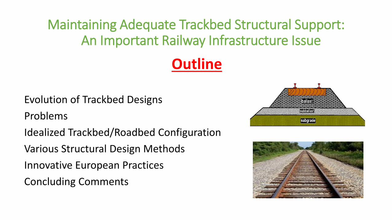
Maintaining Adequate Trackbed Structural Support: An Important Railway Infrastructure Issue
Outline
Evolution of Trackbed Designs
Problems
Idealized Trackbed/Roadbed Configuration
Various Structural Design Methods
Innovative European Practices
Concluding Comments
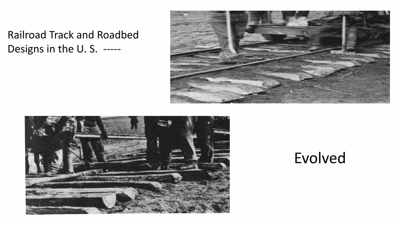
Railroad Track and Roadbed Designs in the U. S. -----
Evolved
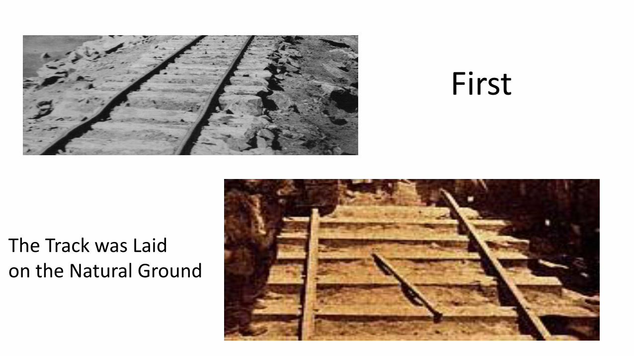
First
The Track was Laid on the Natural Ground

So the All-Granular Trackbed/Roadbed --- Evolved

And is by far the most prominent type of Track Structure today
Plus larger and better rail Plus concrete, steel and composite ties Plus more significant fastenings and OTM
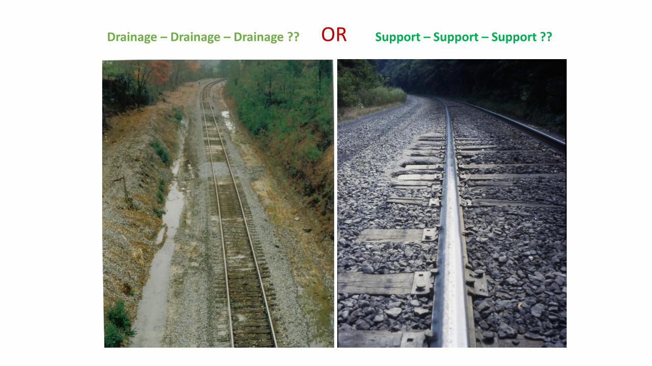
Drainage – Drainage – Drainage ?? OR Support – Support – Support ??
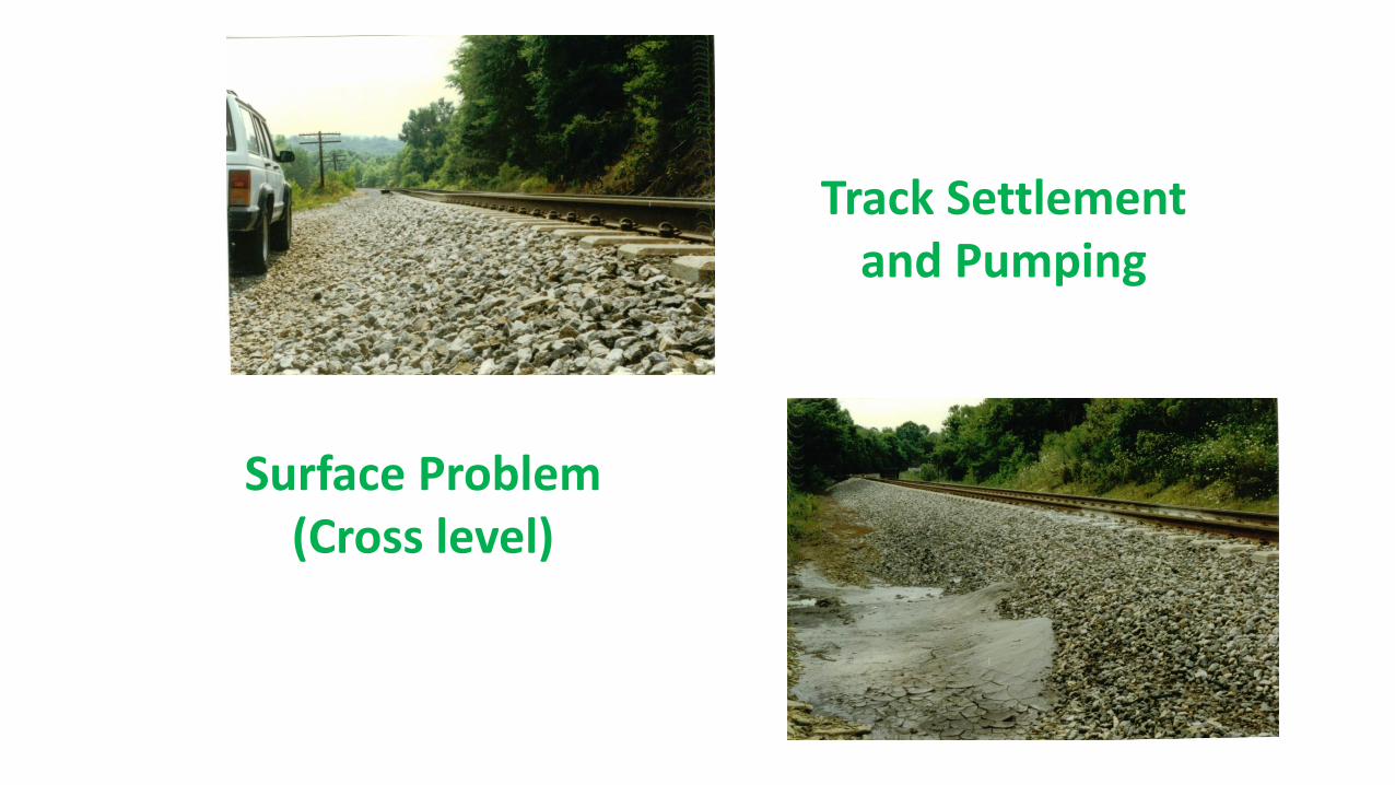
Surface Problem (Cross level)
Track Settlement and Pumping
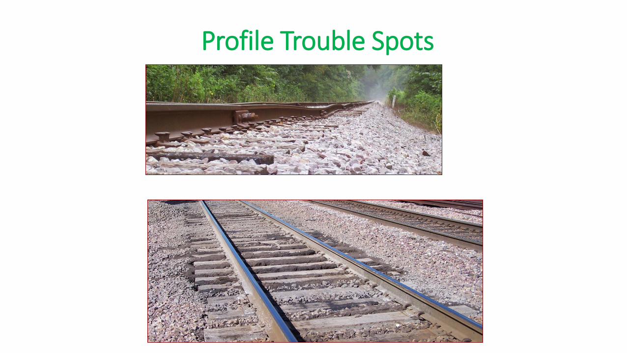
Profile Trouble Spots

Pumping and Settlement
Settlement

Track Surfacing
Purpose: Adjust Geometry --- Horizontally (line) and Vertically (surface and cross level)
Add Ballast Adjust Ballast

Tamper Pulling Track
Restore Geometry
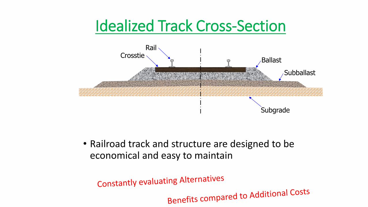
Idealized Track Cross-Section
• Railroad track and structure are designed to be economical and easy to maintain
Rail Crosstie
Ballast
Subgrade
Subballast

• Basic Requirements • Track must support the loadings
and guide the train’s path
• Track Quality Determines • Permissible wheel loadings
• Safe speed of the train
• Maintenance of track geometrics
• Overall safety of operations
• Dependability/Efficiency of operations
• FRA Class of Track -- 1,2,3,4,5,6,7,8,9

Class 1 Track
10 mph or less
Class 4 Track
60 mph freight 80 mph passenger
Class 2 Track
25 mph freight 30 mph passenger
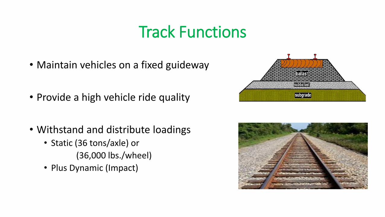
Track Functions
• Maintain vehicles on a fixed guideway
• Provide a high vehicle ride quality
• Withstand and distribute loadings • Static (36 tons/axle) or
(36,000 lbs./wheel)
• Plus Dynamic (Impact)
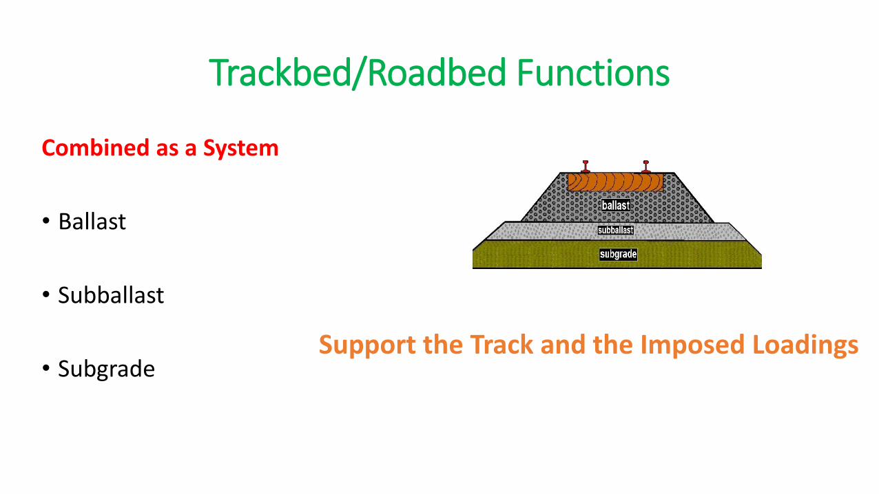
Trackbed/Roadbed Functions
Combined as a System
• Ballast
• Subballast
• Subgrade
Support the Track and the Imposed Loadings

20
Interaction, Vertical Load Distribution, and Deflections
Components do not function independently!
Each component layer must protect the one
below.
Each component contributes.
It is a System…..
Stress Distribution
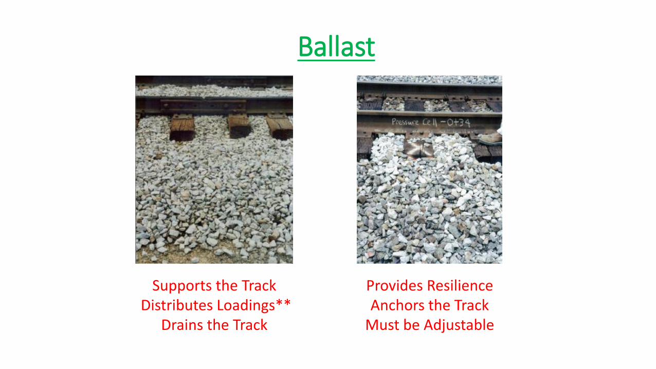
Ballast
Supports the Track Distributes Loadings**
Drains the Track
Provides Resilience Anchors the Track
Must be Adjustable
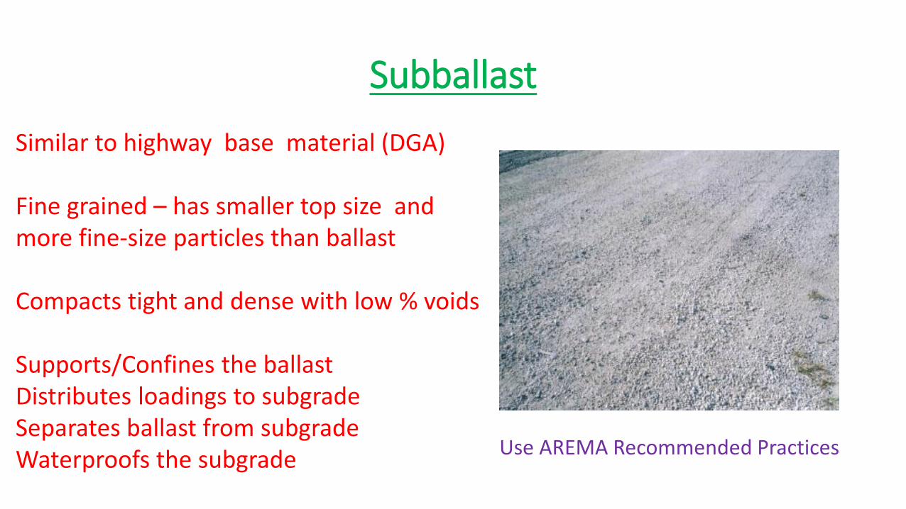
Subballast
Similar to highway base material (DGA) Fine grained – has smaller top size and more fine-size particles than ballast Compacts tight and dense with low % voids Supports/Confines the ballast Distributes loadings to subgrade Separates ballast from subgrade Waterproofs the subgrade
Use AREMA Recommended Practices

Subgrade
• Supports and distributes the loadings
• Confines the subballast
• Facilitates drainage
• Serves as a working platform for roadbed and trackbed
Can be either foundation or embankment
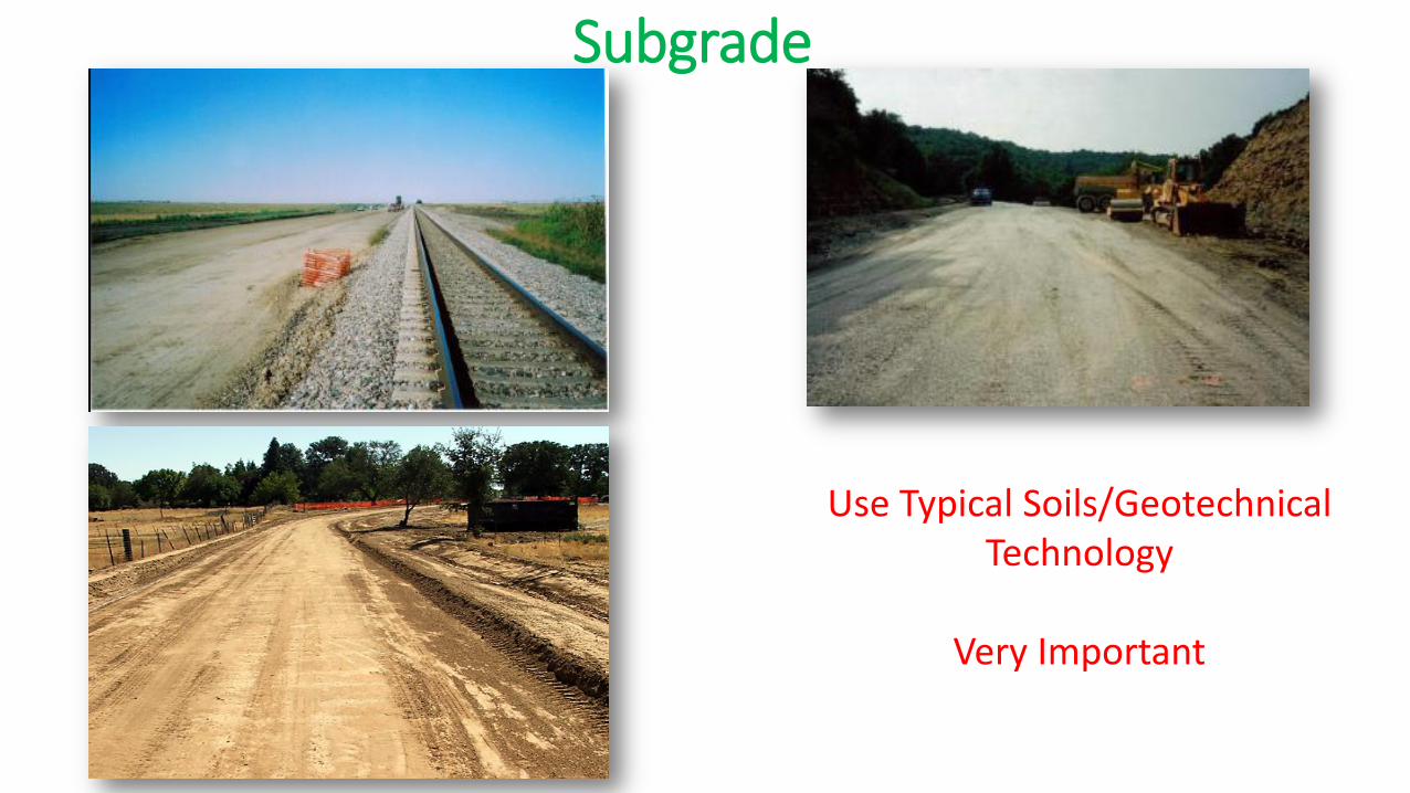
Use Typical Soils/Geotechnical
Technology
Very Important Very Important
Subgrade

Subgrades Vary Must Evaluate Consider Stabilizing Top 2 Feet Important •Stabilize
Subgrade
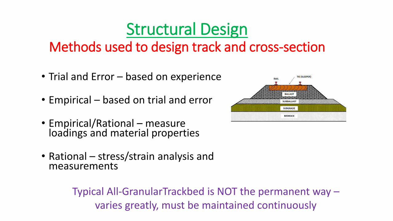
Structural Design Methods used to design track and cross-section
• Trial and Error – based on experience
• Empirical – based on trial and error
• Empirical/Rational – measure
loadings and material properties
• Rational – stress/strain analysis and measurements
Typical All-GranularTrackbed is NOT the permanent way – varies greatly, must be maintained continuously
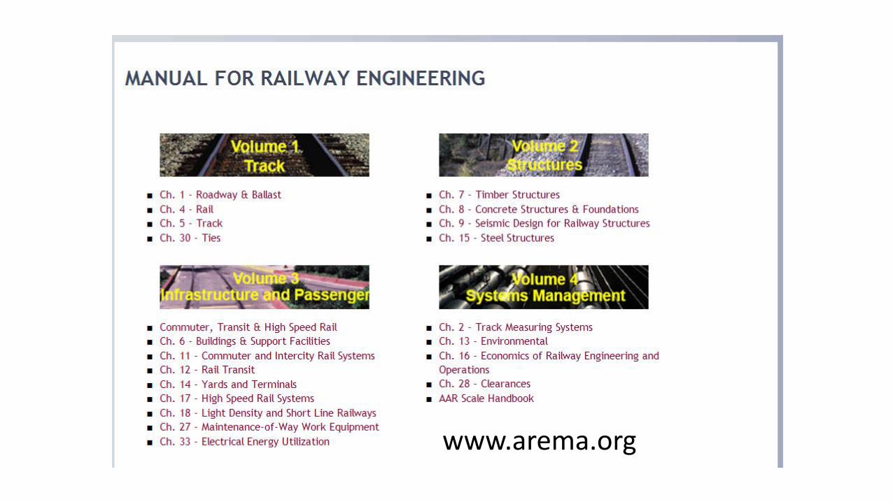
www.arema.org
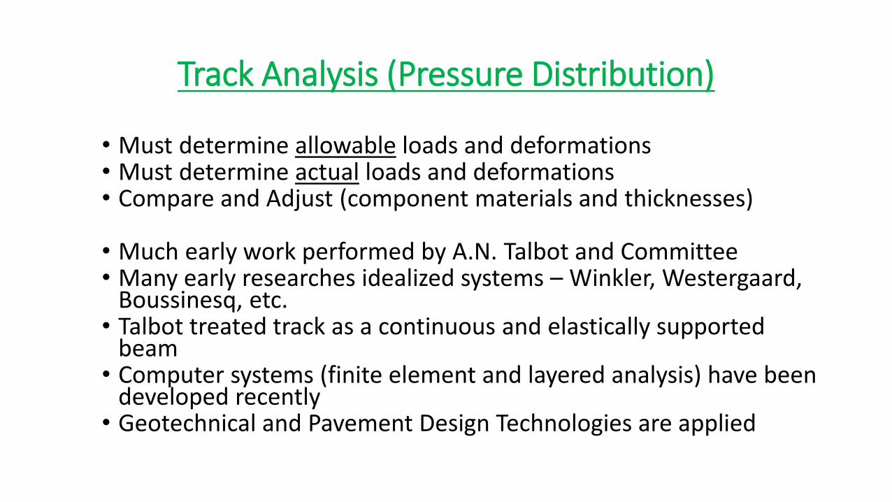
Track Analysis (Pressure Distribution)
• Must determine allowable loads and deformations • Must determine actual loads and deformations • Compare and Adjust (component materials and thicknesses)
• Much early work performed by A.N. Talbot and Committee • Many early researches idealized systems – Winkler, Westergaard,
Boussinesq, etc. • Talbot treated track as a continuous and elastically supported
beam • Computer systems (finite element and layered analysis) have been
developed recently • Geotechnical and Pavement Design Technologies are applied

• Thickness Design
• Talbot
•Pc = 16.8 Pa / h1.25 Subgrade Tie
• Somewhat Arbitrary Standard
• Mainly Empirical
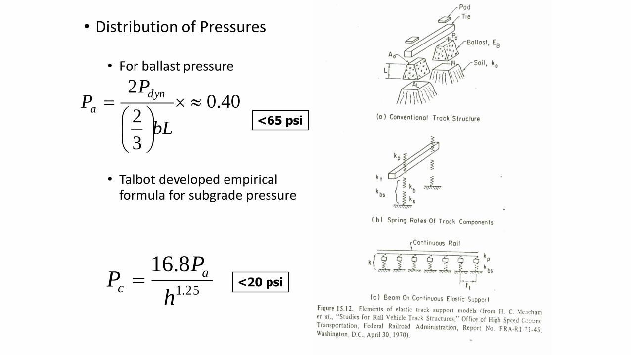
• Distribution of Pressures
• For ballast pressure
• Talbot developed empirical formula for subgrade pressure
40.0
3
2
2
bL
PP
dyn
a<65 psi
25.1
8.16
h
PP a
c <20 psi

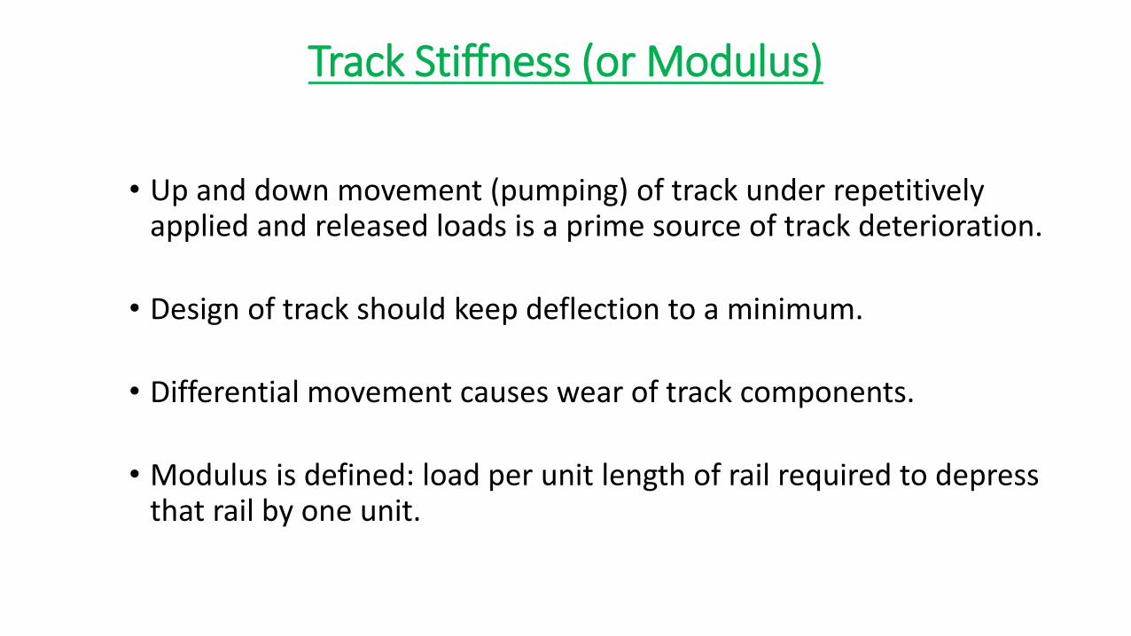
Track Stiffness (or Modulus)
• Up and down movement (pumping) of track under repetitively applied and released loads is a prime source of track deterioration.
• Design of track should keep deflection to a minimum.
• Differential movement causes wear of track components.
• Modulus is defined: load per unit length of rail required to depress that rail by one unit.
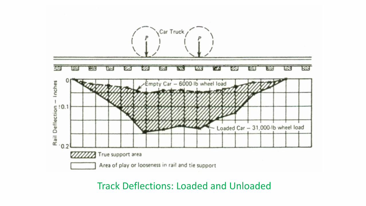
Track Deflections: Loaded and Unloaded

KENTRACK 4.1: A Railway Trackbed Structural Design Program – Rational Method
• Kentrack is a computer program designed to analyze a railroad track segment as a structure
• Uses Bousinessq’s Elastic Theory
• Uses Burmister’s Multi-Layer System and Finite Element Analysis to perform calculations

Kentrack
• Critical Stresses and Strains are Calculated at Various Interfaces within the Track Structure
• Design Lives are Predicted for Trackbed Support Layers based on Fatigue Effects
(Cumulative Damage Criteria) of Repeated Loadings
• Uses DAMA Program – Developed for Highway Pavements (Applicability for RR Trackbeds?)
• Applicable of both Unbound (elastic layers) Granular Trackbeds and Bound (elastic and viscous layers) Granular Trackbeds
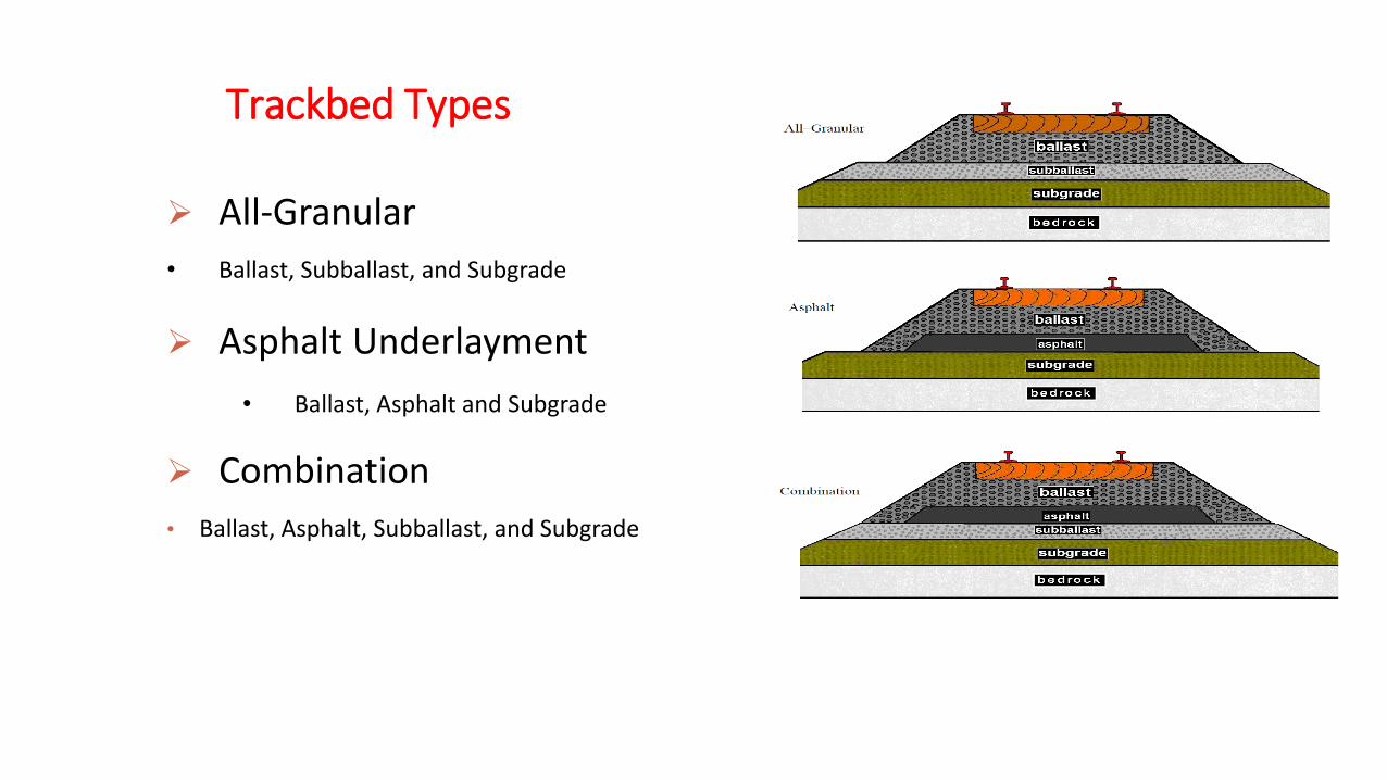
All-Granular
• Ballast, Subballast, and Subgrade
Asphalt Underlayment
• Ballast, Asphalt and Subgrade
Combination
• Ballast, Asphalt, Subballast, and Subgrade
Trackbed Types
An Equal Opportunity University
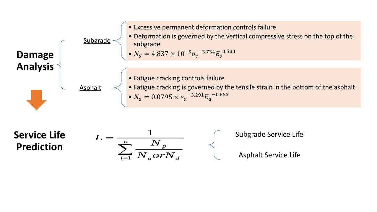
Subgrade
• Excessive permanent deformation controls failure
• Deformation is governed by the vertical compressive stress on the top of the subgrade
• 𝑁𝑑 = 4.837 × 10⁻⁵𝜎𝑐−3.734𝐸𝑠
3.583
Asphalt
• Fatigue cracking controls failure
• Fatigue cracking is governed by the tensile strain in the bottom of the asphalt
• 𝑁𝑎 = 0.0795 × 𝜀𝑎−3.291𝐸𝑎
−0.853
n
i da
p
orNN
NL
1
1Service Life Prediction
Damage Analysis
Subgrade Service Life
Asphalt Service Life

Effects of Varying Subgrade Modulus – Sensitivity Analysis Example
• A very critical parameter influencing the quality and load carrying capability of the track structure.
• A subgrade with high moduli provides a stiffer foundation that has greater bearing capacity and increases load carrying capability.
Subgrade Compressive Stress vs. Modulus Subgrade Service Life vs. Modulus
0
5
10
15
20
6000 12000 18000 24000
Su
bg
rad
e C
om
pre
ssiv
e S
tre
ss
(psi
)
Subgrade Modulus (psi)
All-Granular Trackbed
Asphalt Underlayment Trackbed
Combination Trackbed
0
20
40
60
80
100
120
6000 12000 18000 24000
Su
bg
rad
e S
erv
ice
Lif
e (
yrs
)
Subgrade Modulus (psi)
All-Granular Trackbed
Asphalt Underlayment Trackbed
Combination Trackbed

P-Cell 209 on 5 in. HMA Layer
0
5
10
15
20
7 8 9 10 11 12 13 14 15 16 17
Time (s)
Pre
ss
ure
(p
si)
4 6-Axle Locos
Initial 5 Cars
Empty Coal Train at Conway
05
1015
202530
2 3 4 5 6 7 8 9 10
Time (s)
Str
ess (
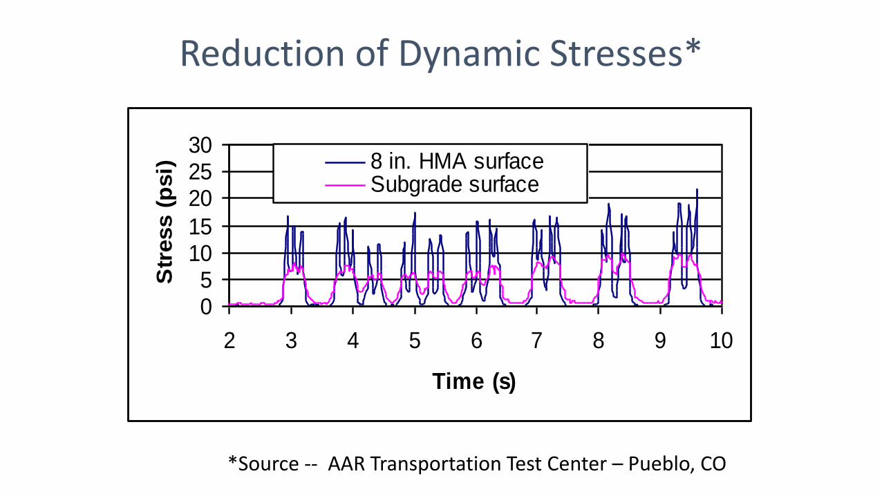
psi) 8 in. HMA surface
Subgrade surface
Reduction of Dynamic Stresses*
*Source -- AAR Transportation Test Center – Pueblo, CO

International Applications Italy France
Japan Spain
Germany
Austria
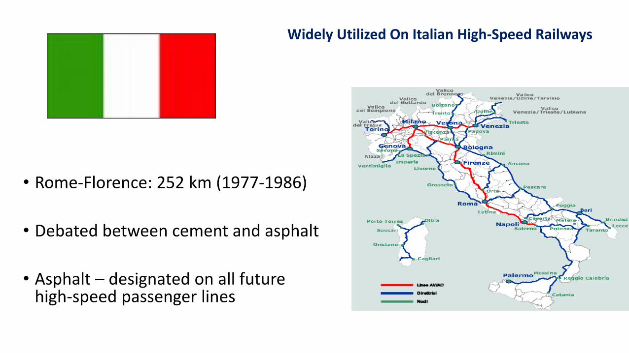
• Rome-Florence: 252 km (1977-1986)
• Debated between cement and asphalt
• Asphalt – designated on all future high-speed passenger lines
Widely Utilized On Italian High-Speed Railways
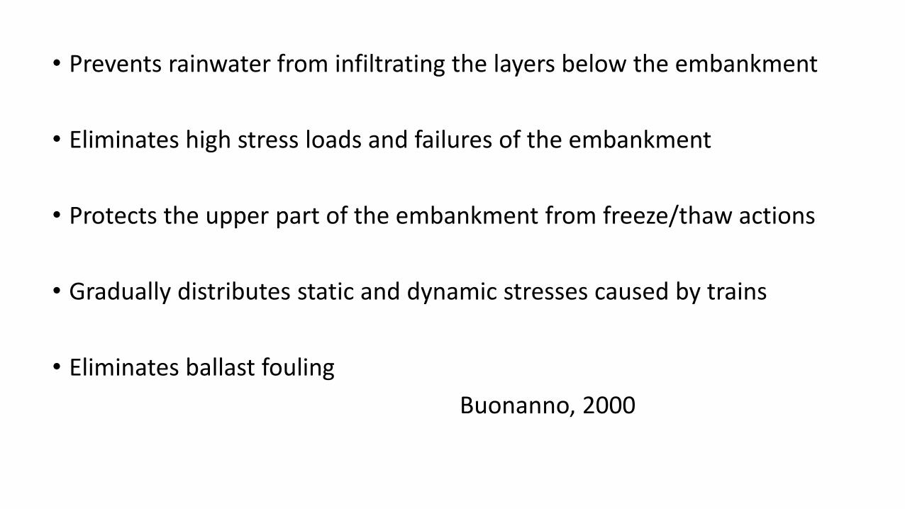
• Prevents rainwater from infiltrating the layers below the embankment
• Eliminates high stress loads and failures of the embankment
• Protects the upper part of the embankment from freeze/thaw actions
• Gradually distributes static and dynamic stresses caused by trains
• Eliminates ballast fouling
Buonanno, 2000

Typical Cross Section
• 12 cm of asphalt with 200 MPa modulus
• 30 cm of super compacted subgrade with 80 MPa modulus
• 35 cm of ballast on top
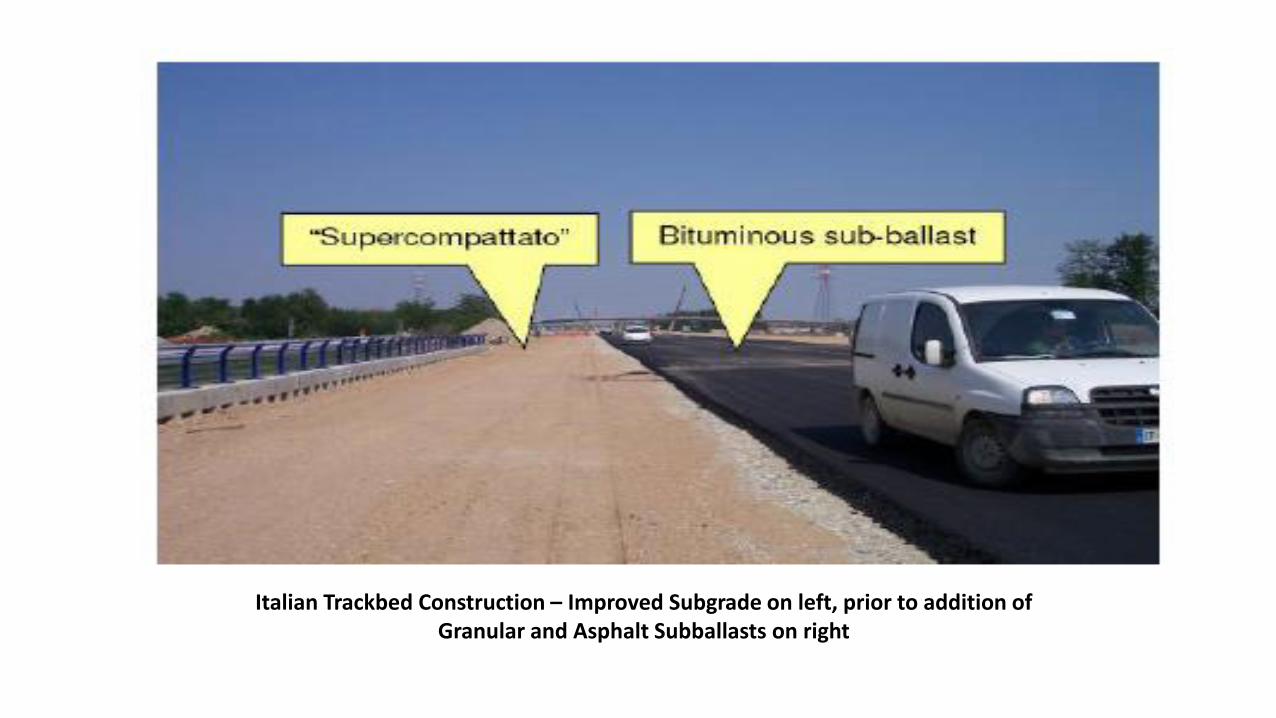
Italian Trackbed Construction – Improved Subgrade on left, prior to addition of Granular and Asphalt Subballasts on right

Policicchio, 2008
Teixeira, 2005
Advantages of Bituminous Subballast

Spreading and Compacting Ballast
Italian Railways Bituminous Trackbed Construction
Compacting Subgrade and Placing/Compacting Asphalt

Falling Weight Deflectometer
for assessing Structural Competency Station View of Completed
Asphalt Trackbed
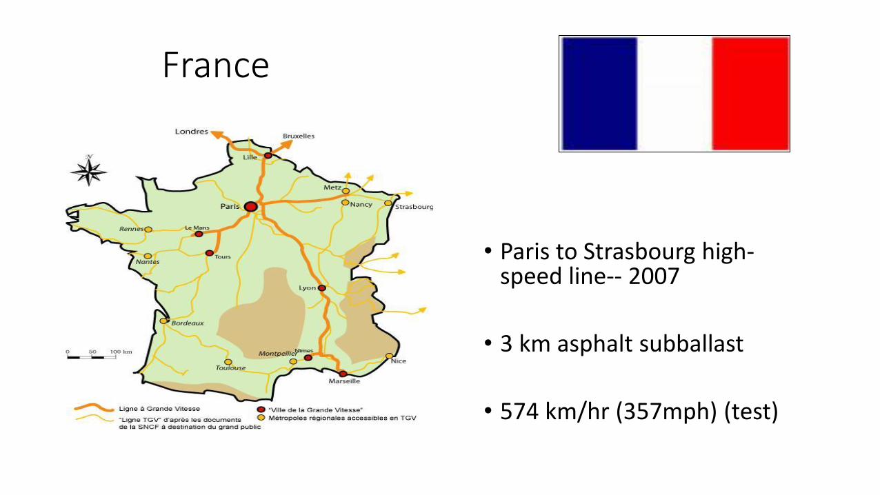
France
• Paris to Strasbourg high-speed line-- 2007
• 3 km asphalt subballast
• 574 km/hr (357mph) (test)

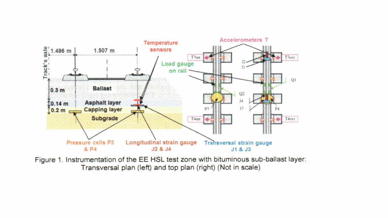
• 3 Km Test zone with Asphalt under ballast
• Instrumentation:
• Temperature Sensors
• Accelerometers on the sleepers
• Strain gauges at the base of the layer of asphalt
• Pressure cells on subgrade support
51
Drawn to the LGV EE (www.rff.fr)
Construction of the test area - layer of pervious
The test area for the LGV EE Case Study
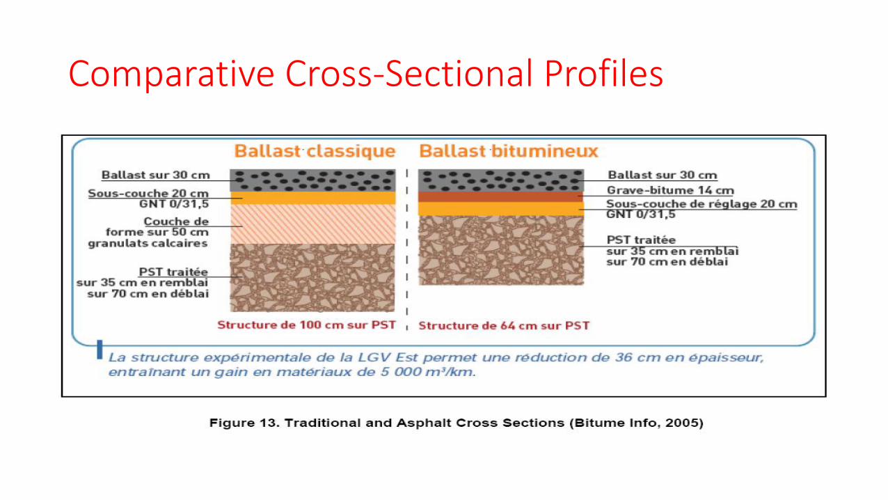
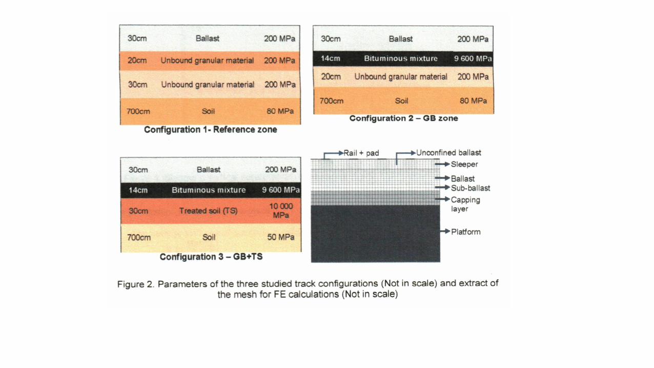
Comparative Cross-Sectional Profiles


Testing
• Conduct tests for 4 years (2007-2011)
• Temperature sensors continuously recording air temperature
• Pressure Sensors and Strain Gages checked twice a year
• Accelerometers
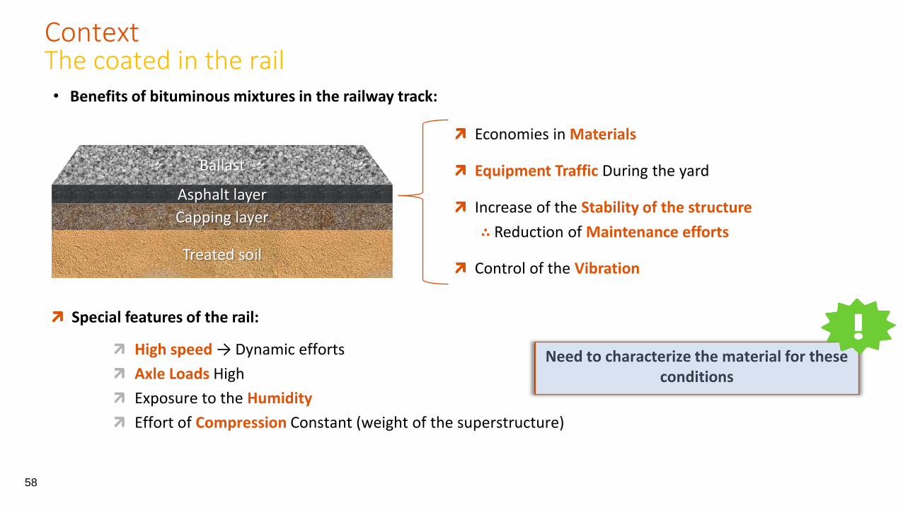
Treated soil
Capping layer
Asphalt layer
Ballast
• Benefits of bituminous mixtures in the railway track:
Economies in Materials
Equipment Traffic During the yard
Increase of the Stability of the structure
∴ Reduction of Maintenance efforts
Control of the Vibration
Special features of the rail:
High speed → Dynamic efforts
Axle Loads High
Exposure to the Humidity
Effort of Compression Constant (weight of the superstructure)
Need to characterize the material for these conditions
58
Context The coated in the rail
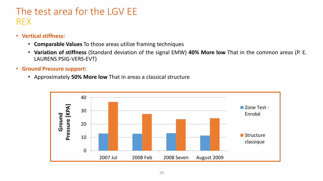
• Vertical stiffness:
• Comparable Values To those areas utilize framing techniques
• Variation of stiffness (Standard deviation of the signal EMW) 40% More low That in the common areas (P. E. LAURENS PSIG-VERS-EVT)
• Ground Pressure support:
• Approximately 50% More low That in areas a classical structure
59
0
10
20
30
40
2007 Jul 2008 Feb 2008 Seven August 2009
Gro
un
d
Pre
ssu
re [
KPA
]
Zone Test -Enrobé
Structureclassique
The test area for the LGV EE REX
60
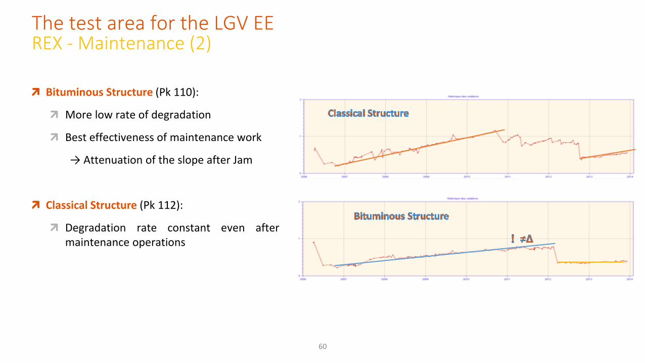
Bituminous Structure (Pk 110):
More low rate of degradation
Best effectiveness of maintenance work
→ Attenuation of the slope after Jam
Classical Structure (Pk 112):
Degradation rate constant even after maintenance operations
The test area for the LGV EE REX - Maintenance (2)

Comments Relative to French Asphalt Track Section
Reduces overall cross-sectional thickness by 36 cm
Reduces quantity of fill material by 5,000 cubic meters/kilometer
Pressures under asphalt layer are one-half of granular sections
Deflections of asphalt track are one-third of allowable
Sleeper acceleration is not affected
Less maintenance is required on asphalt track
Asphalt track performs well
Based on performance, several more sections are planned
Source: Bitume Info, 2005 & Robinette, 2013
Partial Findings • The use of bituminous layers in structure of railway track allows you to reduce the efforts of maintenance
• The complex module and the Poisson coefficient complex are strongly dependent on the frequency of solicitation and the temperature.
• In terms of rigidity, the trains running at high speed does not seem to be problematic for bituminous mixtures.
• The mold flow model 2S2P1D is a tool of great value for the study of bituminous materials
Reference: Characterization of Thermomechanical Properties of Coated Bituminous Rail By: Diego Ramirez Cardona SNCF – French National Railways October 31, 2014

- LGV is European Phase 1:
- 3 Km Test Area
- Large PProject proponents:
- LGV EE phase 2
- LGV Bretagne Country-de-Loire
- LGV Atlantic southern Europe-atlantic
- Workaround
Nimes-Montpellier Large rail projects in France (www.rff.fr)
Rail Experiences with bituminous mixtures:
63
The Wrapped in the rail network French

Austrian Railways

Reasons for Implementing Asphalt Layers
How to install an Asphalt Layer?
drainage effect for raining water hindering it penetrating the substructure
avoiding the pumping up of fines into the ballast delivering a certain amount of elasticity homogenising the stresses affecting the substructure
to allow road vehicles running on the sub-layer during construction phase independently from weather and sub-soil situation
clear separation of sub- and superstructure during the
whole service life
Targets of an Asphalt Layer
Advantages

Long Term Experiences Jauntal, Carinthia
Austrian Railways Conclusions Asphalt layers improve the quality of track in defining a clear and long lasting separation between superstructure and sub-structure. This separation results in less maintenance demands of track and (thus) longer service lives.
These benefits must be paid by an additional investment of 10€/m² within the initial construction.
Life cycle cost analyses show that it is worth to implement asphalt layers on heavy loaded lines (> 15,000 gt per day and track), as then the annual average track cost can be reduced by 3% to 5%.
However, implementation of asphalt layers cannot be proposed for branch lines carrying small transport volumes. Asphalt Layers must be understood as an additional investment in quality, then it pays back its costs. It must not be implemented in order to reduce quality in sub-layers, by for example reducing the thickness of the frost-layers.
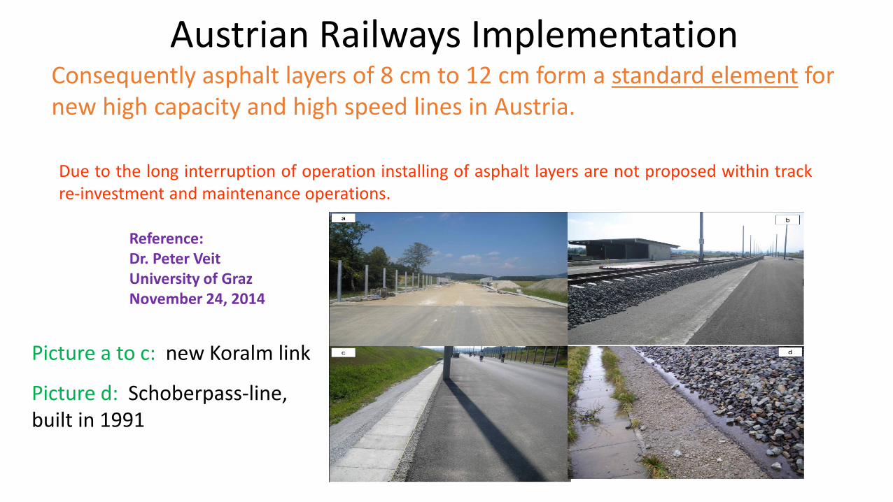
Due to the long interruption of operation installing of asphalt layers are not proposed within track re-investment and maintenance operations.
Austrian Railways Implementation Consequently asphalt layers of 8 cm to 12 cm form a standard element for new high capacity and high speed lines in Austria.
Picture a to c: new Koralm link
Picture d: Schoberpass-line, built in 1991
Reference: Dr. Peter Veit University of Graz November 24, 2014

Concluding Comments
The majority of Railroad Trackbed and Roadbed Designs on the U.S. Railroad System Evolved mainly through Trial and Error; later based on Empirical Measures Essentially all U.S. Trackbed/Roadbeds are composed of All-Granular Support Layers Periodic Maintenance (surfacing) of the track is necessary to maintain the required Track Geometric Features Each Trackbed Support Layer provides specific Qualities; Combined the Layers represent a System Computer Systems (finite element/layered analysis) can be used to Design and Analyze Layered Track Structures – Kentrack was the featured Rational Procedure herein Using the Computer System, the Relative Effects of Various Layer Compositions (Properties) and Thicknesses can be Evaluated – Sensitivity Analysis

Concluding Comments (continued)
There is considerable interest presently by selected International Railway Agencies to develop Innovative Trackbed Structural Design Programs There is considerable interest presently by selected International Railway Agencies to develop Innovative Trackbed Designs and Construction Techniques Recent Innovative Trackbed Structural Designs and Construction Techniques for Italian, French and Austrian Railways were featured The Incorporation of a Constituent Layer of Asphalt within the Track Structure and Follow-Up Performance Evaluations for the three Western European Railway Agencies were highlighted The Asphalt Layer augments or replaces a portion of the Traditional Granular Support Layers providing documented Enhanced Properties to the Track Support Structure

Thank You for Your Attention Questions ???
Recommended