Application Note
LTE-Advanced Carrier Aggregation Measurement
MX269020A-001
Demonstration using Signal Analyzer and Vector Signal Generator
LTE-Advanced FDD Downlink Measurement Software
MX370108A-001 LTE-Advanced FDD IQproducer
MS2690A/MS2691A/MS2692A Signal Analyzer
MG3710A Vector Signal Generator
MX269022A-001LTE-Advanced TDD Downlink Measurement Software
MX370110A-001LTE-Advanced TDD IQproducer
1 MX269020A/MX370108A-E-F-2
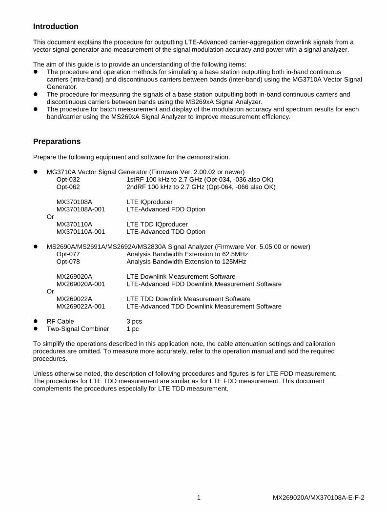
Introduction This document explains the procedure for outputting LTE-Advanced carrier-aggregation downlink signals from a vector signal generator and measurement of the signal modulation accuracy and power with a signal analyzer. The aim of this guide is to provide an understanding of the following items: The procedure and operation methods for simulating a base station outputting both in-band continuous
carriers (intra-band) and discontinuous carriers between bands (inter-band) using the MG3710A Vector Signal Generator.
The procedure for measuring the signals of a base station outputting both in-band continuous carriers and discontinuous carriers between bands using the MS269xA Signal Analyzer.
The procedure for batch measurement and display of the modulation accuracy and spectrum results for each band/carrier using the MS269xA Signal Analyzer to improve measurement efficiency.
Preparations Prepare the following equipment and software for the demonstration. MG3710A Vector Signal Generator (Firmware Ver. 2.00.02 or newer) Opt-032 1stRF 100 kHz to 2.7 GHz (Opt-034, -036 also OK)
Opt-062 2ndRF 100 kHz to 2.7 GHz (Opt-064, -066 also OK) MX370108A LTE IQproducer MX370108A-001 LTE-Advanced FDD Option Or MX370110A LTE TDD IQproducer MX370110A-001 LTE-Advanced TDD Option
MS2690A/MS2691A/MS2692A/MS2830A Signal Analyzer (Firmware Ver. 5.05.00 or newer) Opt-077 Analysis Bandwidth Extension to 62.5MHz Opt-078 Analysis Bandwidth Extension to 125MHz
MX269020A LTE Downlink Measurement Software MX269020A-001 LTE-Advanced FDD Downlink Measurement Software Or MX269022A LTE TDD Downlink Measurement Software MX269022A-001 LTE-Advanced TDD Downlink Measurement Software
RF Cable 3 pcs Two-Signal Combiner 1 pc To simplify the operations described in this application note, the cable attenuation settings and calibration procedures are omitted. To measure more accurately, refer to the operation manual and add the required procedures. Unless otherwise noted, the description of following procedures and figures is for LTE FDD measurement. The procedures for LTE TDD measurement are similar as for LTE FDD measurement. This document complements the procedures especially for LTE TDD measurement.

2 MX269020A/MX370108A-E-F-2
Overview of Carrier Aggregations Carrier Aggregation (CA) is a technique to occupy wider transmission bandwidth for increasing communication speed, capacity and quality by aggregating multiple carriers. CA can be used for both FDD and TDD. The downlink and uplink can be configured completely independently. One of aggregated carriers is called Component Carrier (CC). With a maximum of five component carriers, the maximum aggregated bandwidth is 100 MHz.
Fig. 1. Carrier Aggregation
The three types of CA are defined by configuration of component carriers, which are Intra-band contiguous CA, Intra-band non-contiguous CA, and Inter-band non-contiguous CA. Intra-band contiguous CA allocates multiple component carriers contiguously within the same operating band. Intra-band contiguous CA does not permit another carrier to transmit inside of component carriers of contiguous CA. Intra-band contiguous CA is applicable when an operator acquires contiguous bandwidth wider than 20 MHz and it is available for the transmission or reception. Intra-band non-contiguous CA allocates multiple component carriers with some gaps for other carriers in an operating band. Intra-band non-contiguous CA is valuable for an operator acquires only intermittent bandwidths in an operating band, or when there are some bandwidths for any other system inside of LTE bandwidth. Inter-band non-contiguous CA aggregates component carriers belong to different operating bands. Inter-band non-contiguous CA can activate separate operating bands to increase communication capacity for a specific data stream.
Intra-band Contiguous CA Intra-band Non-Contiguous CA
Inter-band Non-Contiguous CA
Fig. 2. Different type of CA allocation
3 MX269020A/MX370108A-E-F-2
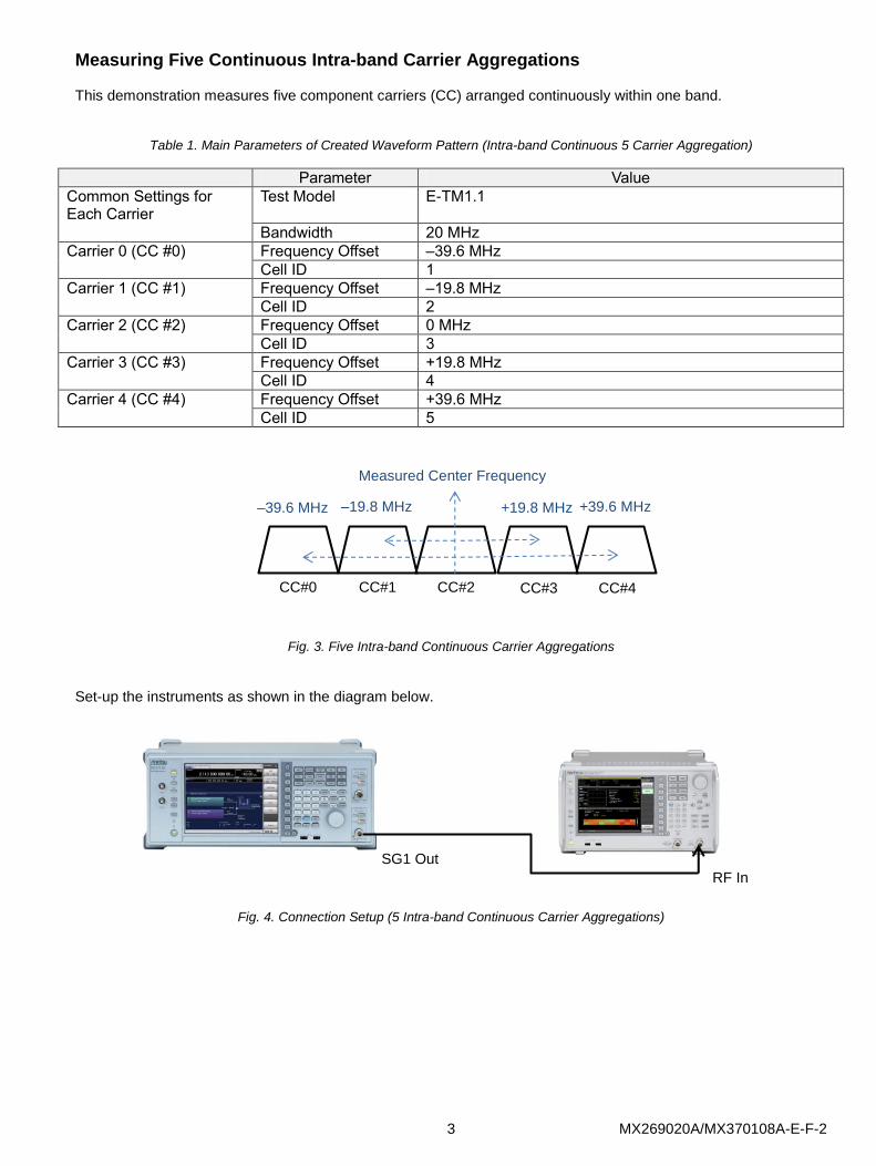
Measuring Five Continuous Intra-band Carrier Aggregations This demonstration measures five component carriers (CC) arranged continuously within one band.
Table 1. Main Parameters of Created Waveform Pattern (Intra-band Continuous 5 Carrier Aggregation)
Parameter Value
Common Settings for Each Carrier
Test Model E-TM1.1
Bandwidth 20 MHz
Carrier 0 (CC #0) Frequency Offset –39.6 MHz
Cell ID 1
Carrier 1 (CC #1) Frequency Offset –19.8 MHz
Cell ID 2
Carrier 2 (CC #2) Frequency Offset 0 MHz
Cell ID 3
Carrier 3 (CC #3) Frequency Offset +19.8 MHz
Cell ID 4
Carrier 4 (CC #4) Frequency Offset +39.6 MHz
Cell ID 5
Fig. 3. Five Intra-band Continuous Carrier Aggregations
Set-up the instruments as shown in the diagram below.
Fig. 4. Connection Setup (5 Intra-band Continuous Carrier Aggregations)
CC#0 CC#1 CC#2 CC#3 CC#4
Measured Center Frequency
–19.8 MHz –39.6 MHz +39.6 MHz +19.8 MHz
SG1 Out
RF In

4 MX269020A/MX370108A-E-F-2
Signal Generation and Output: Vector Signal Generator Operations Use IQproducer in the MG3710A to create the output signal waveform pattern. The MG3710A Vector Signal Generator operation procedure is described below. [Procedure] 1. Press [Preset] [F3] Preset All. 2. Press [IQpro] to start IQproducer. 3. Press [LTE FDD] ([LTE TDD] for TDD) at the System (Cellular) tab to start LTE IQproducer. 4. Set System to LTE-Advanced. 5. Set Carrier Aggregation Mode to Intra-band. 6. Put a check mark in each Status checkbox for Component Carrier. 7. Press [E-TM1.1] for Component Carrier 0.
Set Bandwidth to 20 MHz and Cell ID to 1 and press [OK]. Set Freq Offset for Component Carrier 0 to –39.6 MHz.
8. Press [E-TM1.1] for Component Carrier 1. Set Bandwidth to 20 MHz and Cell ID to 2 and press [OK]. Set Freq Offset for Component Carrier 1 to –19.8 MHz.
9. Press [E-TM1.1] for Component Carrier 2. Set Bandwidth to 20 MHz and Cell ID to 3 and press [OK]. Set Freq Offset for Component Carrier 2 to 0 MHz.
10. Press [E-TM1.1] for Component Carrier 3. Set Bandwidth to 20 MHz and Cell ID to 4 and press [OK]. Set Freq Offset for Component Carrier 3 to +19.8 MHz.
11. Press [E-TM1.1] for Component Carrier 4. Set Bandwidth to 20 MHz and Cell ID to 5 and press [OK]. Set Freq Offset for Component Carrier 4 to +39.6 MHz.
Fig. 5. IQproducer Settings (5 Intra-band Continuous Carrier Aggregations)
12. Press [Calculation & Play].
The package name is LTE-A_FDD (“LTE-A_TDD” for TDD) and the pattern name is 5CCs_E-TM. 13. When the Select SG window is displayed, select SG1.
*To shorten the demonstration time, we recommend pre-creating the waveform.

5 MX269020A/MX370108A-E-F-2
14. Press [SG1] after waveform creation completes. 15. Press [Frequency] and set the center frequency to 2110 MHz. 16. Press [Level] and set the output level to –10 dBm. 17. Press [I/Q] [F3] Internal Channel Correction to set On. 18. Press [I/Q] [F6] Wideband to set On.
*Steps 17 and 18 set the priority of the MG3710A Vector Signal Generator output signal intra-band characteristics.
19. Press RF Output [Mod On/Off] and [On/Off] to output the modulation signal.
Signal Analyzer Operations The signal analyzer measurement procedure is described below. [Procedure] 1. Press [Application Switch] and select [3GLTE Downlink] (LTE-TDD Downlink for TDD). 2. Press [Preset] [F1] Preset.
3. Press [Measure] [] (Function Menu page 2) [F1] Batch Measurement. 4. Press [F1] Batch Settings. 5. Press [F2] Band Settings. 6. Set the Band Settings parameters as follows:
Band #0 Checked
Band #0 Carrier Frequency 2110 MHz
Band #0 OBUE Standard Wide BS Cat. A 1-3G
Band #0 Contiguous Mode On
Band #1, #2 Unchecked 7. Press [F3] Component Carrier Settings. 8. Set the Component Carrier Settings parameters as follows:
CC #0, 1, 2, 3, 4 Checked
CC #0 Frequency Band Band #0
CC #0 Frequency Offset –39.6 MHz
CC #0 Bandwidth 20 MHz
CC #0 Test Model E-TM1.1
CC #1 Frequency Band Band #0
CC #1 Frequency Offset –19.8 MHz
CC #1 Bandwidth 20 MHz
CC #1 Test Model E-TM1.1
CC #2 Frequency Band Band #0
CC #2 Frequency Offset 0 MHz
CC #2 Bandwidth 20 MHz
CC #2 Test Model E-TM1.1
CC #3 Frequency Band Band #0
CC #3 Frequency Offset +19.8 MHz
CC #3 Bandwidth 20 MHz
CC #3 Test Model E-TM1.1
CC #4 Frequency Band Band #0
CC #4 Frequency Offset +39.6 MHz
CC #4 Bandwidth 20 MHz
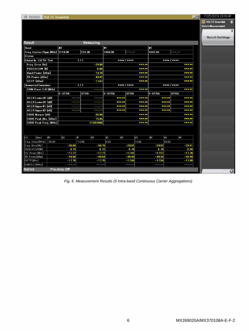
CC #4 Test Model E-TM1.1 9. Press [F7] Set. 10. Press [Single] to start measurement. The measurement results for each band are displayed at the top of the screen and the measurement results for each component carrier are displayed at the bottom.
6 MX269020A/MX370108A-E-F-2
Fig. 6. Measurement Results (5 Intra-band Continuous Carrier Aggregations)

7 MX269020A/MX370108A-E-F-2
The waveforms monitored by the spectrum analyzer appear as shown below. We can see that CC #0, #1, #2, #3 and #4 appear sequentially from the left of the screen.
Fig. 7. Spectrum Display (5 Intra-band Continuous Carrier Aggregations)
8 MX269020A/MX370108A-E-F-2
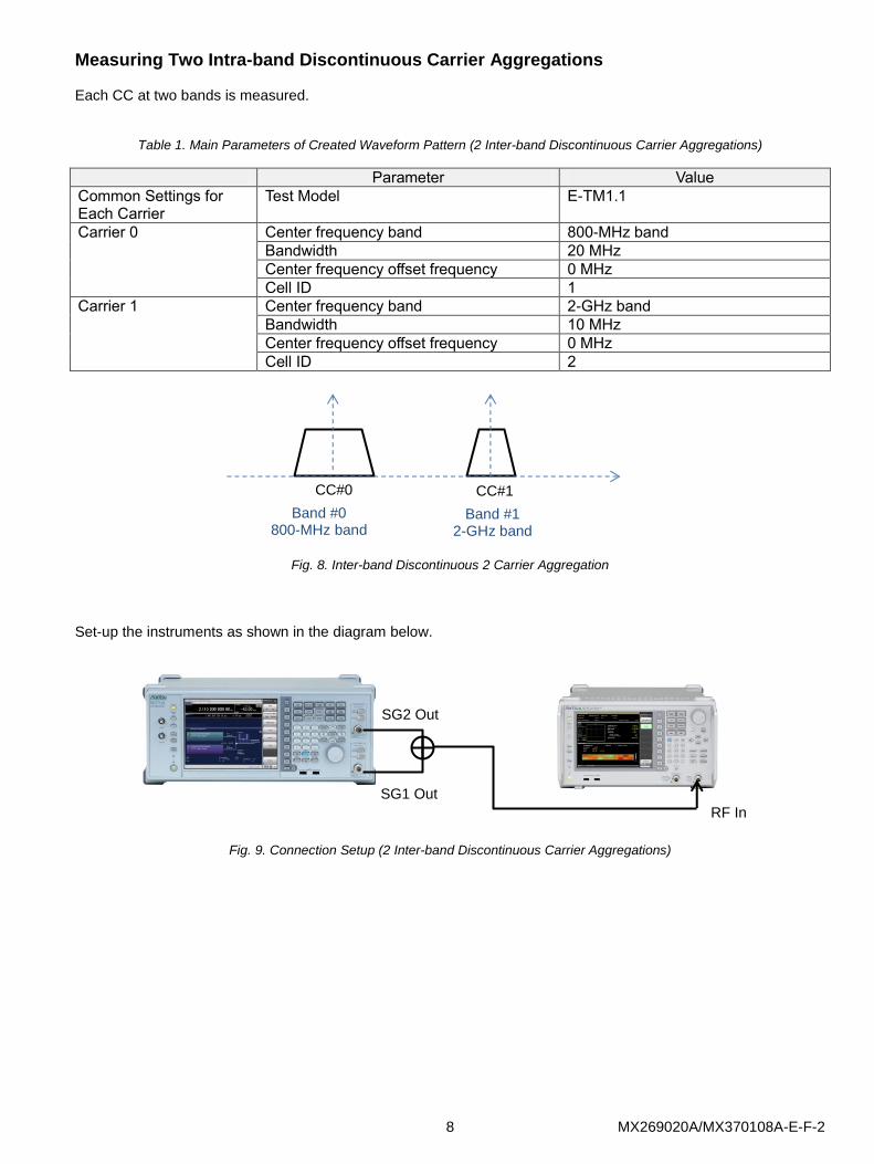
Measuring Two Intra-band Discontinuous Carrier Aggregations Each CC at two bands is measured.
Table 1. Main Parameters of Created Waveform Pattern (2 Inter-band Discontinuous Carrier Aggregations)
Parameter Value
Common Settings for Each Carrier
Test Model E-TM1.1
Carrier 0 Center frequency band 800-MHz band
Bandwidth 20 MHz
Center frequency offset frequency 0 MHz
Cell ID 1
Carrier 1 Center frequency band 2-GHz band
Bandwidth 10 MHz
Center frequency offset frequency 0 MHz
Cell ID 2
Fig. 8. Inter-band Discontinuous 2 Carrier Aggregation
Set-up the instruments as shown in the diagram below.
Fig. 9. Connection Setup (2 Inter-band Discontinuous Carrier Aggregations)
SG2 Out
SG1 Out
RF In
CC#0 CC#1
Band #0 800-MHz band
Band #1 2-GHz band

9 MX269020A/MX370108A-E-F-2
Signal Creation and Output: Vector Signal Generator Operations Use IQproducer built into the MG3710A to create the output signal pattern. The MG3710A Vector Signal Generator operation procedure is described below. [Procedure] 1. Press [IQpro] to start IQproducer. 2. Press [LTE FDD] ([LTE TDD] for TDD) at the System (Cellular) tab to start LTE IQproducer. 3. Set System to LTE-Advanced. 4. Set Carrier Aggregation Mode to Inter-band. 5. Select the Band #0 tab. 6. Put a check mark in the Status checkbox for Band #0 Component Carrier 0. 7. Press [E-TM1.1] for Band #0 Component Carrier 0. 8. Set Band #0 Bandwidth to 20 MHz and Cell ID to 1 and press [OK]. 9. Select the Band #1 tab. 10. Put a check mark in the Status checkbox for Band #1 Component Carrier 0. 11. Press [E-TM1.1] for Band #1 Component Carrier 0. 12. Set Band #1 Bandwidth to 10 MHz and Cell ID to 1 and press [OK].
Fig. 10. IQproducer Settings (Inter-band Discontinuous 2 Carrier Aggregations)
13. Press [Calculation & Play].
The package name is LTE-A_FDD (“LTE-A_TDD” for TDD)and the pattern name is 2Bands_E-TM. 14. When the SG Setting window is displayed, set the frequency and level for SG1 and SG2 and press [OK].
Use the following settings in this demonstration: SG1 Frequency 2110 MHz SG1 Amplitude –10 dBm SG2 Frequency 800 MHz SG2 Amplitude –10 dBm
15. Press RF Output [Mod On/Off] and [On/Off] to output the modulation signal. 16. Press 2nd RF Output [Mod On/Off] and [On/Off] to output the modulation signal.
10 MX269020A/MX370108A-E-F-2
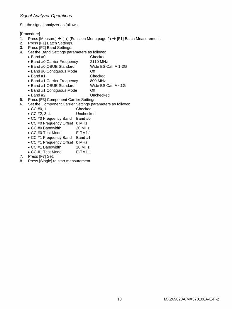
Signal Analyzer Operations Set the signal analyzer as follows: [Procedure]
1. Press [Measure] [] (Function Menu page 2) [F1] Batch Measurement. 2. Press [F1] Batch Settings. 3. Press [F2] Band Settings. 4. Set the Band Settings parameters as follows:
Band #0 Checked
Band #0 Carrier Frequency 2110 MHz
Band #0 OBUE Standard Wide BS Cat. A 1-3G
Band #0 Contiguous Mode Off
Band #1 Checked
Band #1 Carrier Frequency 800 MHz
Band #1 OBUE Standard Wide BS Cat. A <1G
Band #1 Contiguous Mode Off
Band #2 Unchecked 5. Press [F3] Component Carrier Settings. 6. Set the Component Carrier Settings parameters as follows:
CC #0, 1 Checked
CC #2, 3, 4 Unchecked
CC #0 Frequency Band Band #0
CC #0 Frequency Offset 0 MHz
CC #0 Bandwidth 20 MHz
CC #0 Test Model E-TM1.1
CC #1 Frequency Band Band #1
CC #1 Frequency Offset 0 MHz
CC #1 Bandwidth 10 MHz
CC #1 Test Model E-TM1.1 7. Press [F7] Set. 8. Press [Single] to start measurement.
11 MX269020A/MX370108A-E-F-2
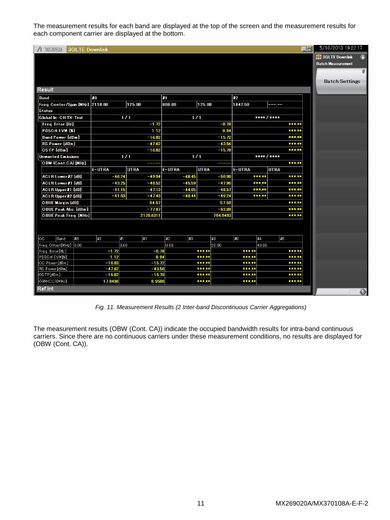
The measurement results for each band are displayed at the top of the screen and the measurement results for each component carrier are displayed at the bottom.
Fig. 11. Measurement Results (2 Inter-band Discontinuous Carrier Aggregations)
The measurement results (OBW (Cont. CA)) indicate the occupied bandwidth results for intra-band continuous carriers. Since there are no continuous carriers under these measurement conditions, no results are displayed for (OBW (Cont. CA)).
12 MX269020A/MX370108A-E-F-2
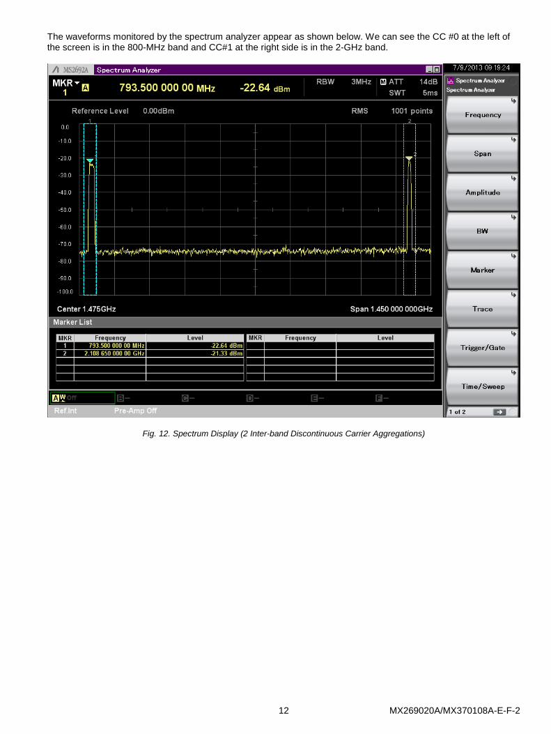
The waveforms monitored by the spectrum analyzer appear as shown below. We can see the CC #0 at the left of the screen is in the 800-MHz band and CC#1 at the right side is in the 2-GHz band.
Fig. 12. Spectrum Display (2 Inter-band Discontinuous Carrier Aggregations)

No. MX269020A/MX370108A-E-F-2-(4.00) Printed in Japan 2014-4 MG
Recommended