Low damage integration of ultralow -k porous organosilicate glasses by Pore-Stuffing approach
L. Zhanga,b, J.-F. de Marneffea, M. Heynea, F. Vajdaa, V. D. Rutigliania, L. Wena, Jurgen Bommela, Z. Tokeia, S. de Gendta,b and M. R. Baklanova
a IMEC vzw, 3001 Leuven, Belgiumb Katholieke Universiteit Leuven, 3001 Leuven, Belgium
PESM2014, Grenoble (France)
2© IMEC 2013/ CONFIDENTIAL LIPING ZHANG
Outline
i. Cu/low-k interconnect and plasma induced damage
ii. Pore stuffing - Process flow
iii. Plasma Induced Damage
iv. Integration flow with Pore Stuffing
v. Summary

3© IMEC 2013/ CONFIDENTIAL LIPING ZHANG
Cu/low -k interconnect
- Interconnect RC delay will dominate the total time delay as IC scales down.
- Cu/low-k interconnect was introduced to replace Al/ SiO2.
+⋅⋅⋅⋅≈22
20
112
TWLRC εκρ Al → Cu
3.0 → 1.72×10⁻⁸ ΩmSiO2 → Low-k4.2 → 3.7-1.8
ITRS, 2011
4© IMEC 2013/ CONFIDENTIAL LIPING ZHANG
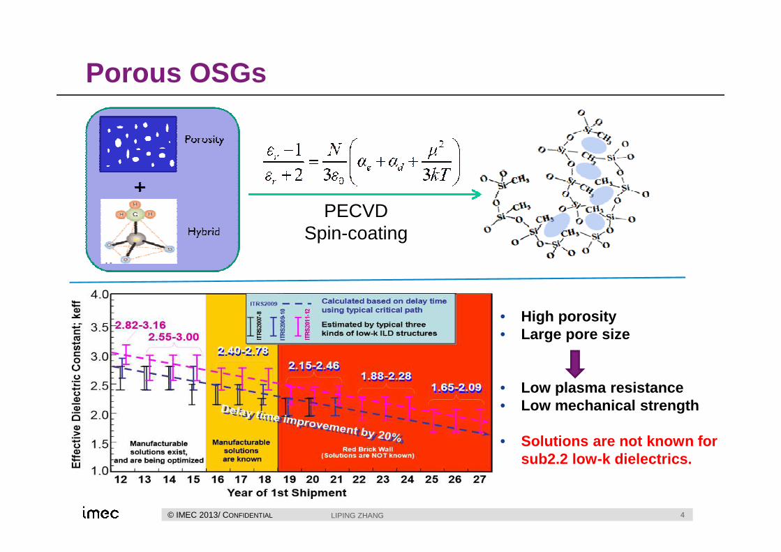
Porous OSGs
• High porosity• Large pore size
• Low plasma resistance• Low mechanical strength
• Solutions are not known for sub2.2 low-k dielectrics.
PECVDSpin-coating

5© IMEC 2013/ CONFIDENTIAL LIPING ZHANG
Plasma Induced Damage (PID)
Radical
n H2OOO Si—CH3OO Si—CH3OO Si—CH3OO Si—CH3O
Moisture uptake leads to increasing of k-value & leaka ge current
OSG before etch
Por
e
OO Si—OHOO Si—OHOO Si—OHOO Si—OHO
3 H2O
b
UV, VUV
OSG post etch
IonRadicalPhoton
plasma
OSG
substrate
PID sidewall
HMHM
PID bottom
- Plasma process is widely used in BEOL, for example: Deposition, Cleaning and Patterning.
- Depth of damage increases with porosity and pore size: L~ a*d*N 0.5 (Random Walk Theory).
N = <number> of collisions before recombination; d = pore diameter; a = distance for a jump; L = depth of penetration.
- Reducing PID is a crucial challenge for porous OSG integration.
Material K-value
SiO2 3.8
Low-k 1.8-2.4
Water 79
6© IMEC 2013/ CONFIDENTIAL LIPING ZHANG
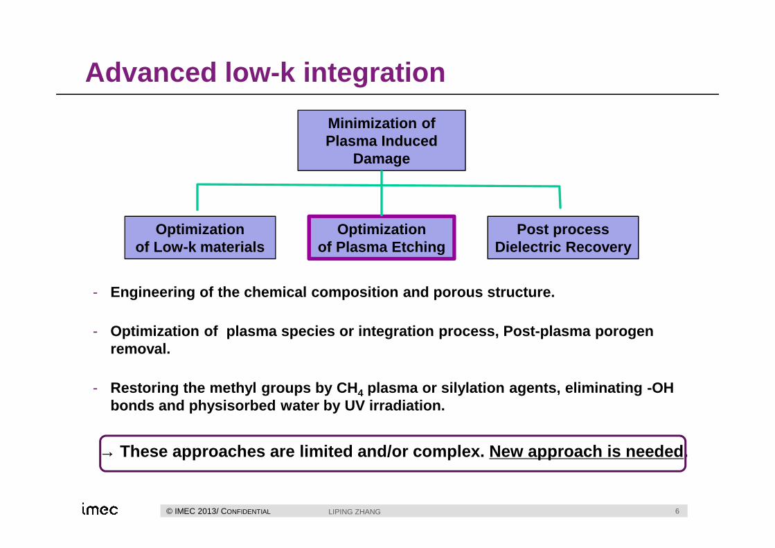
Advanced low -k integration
Minimization of Plasma Induced
Damage
Optimization of Low-k materials
Optimization of Plasma Etching
Post processDielectric Recovery
- Engineering of the chemical composition and porous structure.
- Optimization of plasma species or integration proc ess, Post-plasma porogenremoval.
- Restoring the methyl groups by CH 4 plasma or silylation agents, eliminating -OH bonds and physisorbed water by UV irradiation.
→ These approaches are limited and/or complex. New ap proach is needed.
7© IMEC 2013/ CONFIDENTIAL LIPING ZHANG
Outline
i. Cu/low-k interconnect and plasma induced damage
ii. Pore stuffing - Process flow
iii. Plasma Induced Damage
iv. Integration flow with Pore Stuffing
v. Summary
8© IMEC 2013/ CONFIDENTIAL LIPING ZHANG
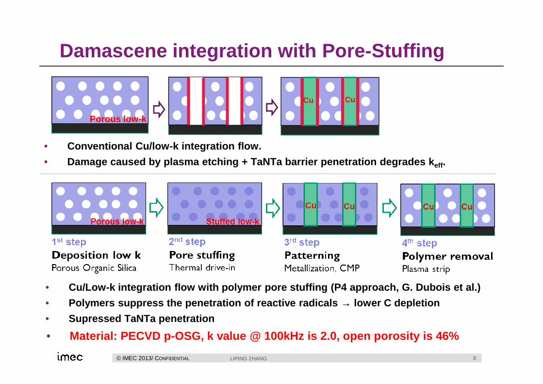
Damascene integration with Pore -Stuffing
CuCu
Porous low-k
• Conventional Cu/low-k integration flow.
• Damage caused by plasma etching + TaNTa barrier pene tration degrades k eff.
• Cu/Low-k integration flow with polymer pore stuffin g (P4 approach, G. Dubois et al.)
• Polymers suppress the penetration of reactive radic als → lower C depletion
• Supressed TaNTa penetration
• Material: PECVD p-OSG, k value @ 100kHz is 2.0, open porosity is 46%

9© IMEC 2013/ CONFIDENTIAL LIPING ZHANG
Polymer Stuffing
- De-wetting issue due to ultra-low surface energy of low-k. A surface activation process by CO2 plasma is used.
- Polymer penetration is driven by capillary force, affected by molecular size, pore size and annealing conditions.

10© IMEC 2013/ CONFIDENTIAL
(a) TOF-SIMS carbon depth profile shows polymers penetrate into bulk low-k until bottom. Surface depletion layer is observed for over removal process.
(b) Ellipsometer Porosity with 0% open porosity, confirming the stuffed state.
LIPING ZHANG
Surface polymer removal
• Solvent need to be adapted to polymer (PGMEA for PMMA, Water for PEG)
• Preferably high surface tension that dos not wet low-k → polymer inside low-k will not be removed.
• Solvent spin cleaning process is optimized to avoid surface polymer depletion.
TOF-SIMSCarbon depth
profile
EllipsometryPorosimetry

11© IMEC 2013/ CONFIDENTIAL LIPING ZHANG
Polymer unstuffingPolymer removal by thermal annealing
• Polymer degradation process → no low-k damage
• Limited by BEOL process thermal budget (< 420°C)
Polymer removal by downstream plasma (DSP)
• Low temperature process (250°C), High polymer removal efficiency. DSP causes low-k damage: formation of Si-OH & k-value increase.

12© IMEC 2013/ CONFIDENTIAL LIPING ZHANG
Outline
i. Cu/low-k interconnect and plasma induced damage
ii. Pore stuffing - Process flow
iii. Plasma Induced Damage
iv. Integration flow with Pore Stuffing
v. Summary

13© IMEC 2013/ CONFIDENTIAL LIPING ZHANG
Plasma Induced Damage
1300 1280 1260 1240 1220
0.00
0.05
0.10
0.15
0.20
0.25
0.30
0.35
N
orm
aliz
ed a
bsor
ptio
n (a
.u.)
Wavenumber cm-1
ArCF4_30s with PMMA ArCF4_30s without PMMA ArNF3_20s with PMMA ArNF3_20s without PMMA ArSF6_20s with PMMA ArSF6_20s without PMMA Pristine p-OSG
Si-Me
67,4
79,3
54,5
94,1
21,2
25,3
56,2
26,1
0
50
100
150
200
250
300
Thi
ckne
ss a
fter
etch
(nm
)
Plasma chemistry and etch time
Non-damaged layer Damaged layer
7,2
11,1
2,4
9,8
-0,4
11,2
15,8
18,1
0
50
100
150
200
250
300
Plasma chemistry and etch time
Non-damaged layer Damaged layer
• FTIR enable tracing water uptake and Si-CH3 loss (PID).
• Based on loss of Si-Me and thickness, Equivalent Damaged Layer (EDL) is calculated.

14© IMEC 2013/ CONFIDENTIAL LIPING ZHANG
Fluorocarbon gas discharges
1300 1250 1200 1150 1100 1050 1000 950
0.0
0.2
0.4
0.6
0.8
1.0
N
orm
aliz
ed a
bsor
ptio
n (a
.u.)
Wavenumber (cm-1)
PMMA protected Non protected Pristine p-OSG
Plasma ChemistryAr/CF 4/CH2F2
• Fluorocarbon plasma is normally used for low-k etching. Due to protection of surface polymerizing effect, low damage is also obtained with blanket test.
• However, this does not apply to patterned test, where high sidewall damage is observed.
• With Pore stuffing, sidewall damage is greatly improved even with O2 containing plasma.
• Trench etch condition is quite different from blanket film etching.
15© IMEC 2013/ CONFIDENTIAL LIPING ZHANG
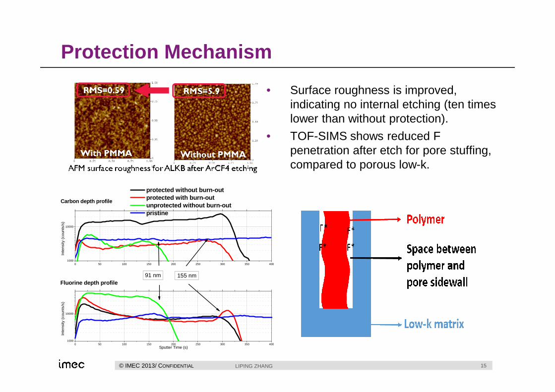
Protection Mechanism
0 50 100 150 200 250 300 350 4001000
10000
0 50 100 150 200 250 300 350 4001000
10000
protected without burn-out protected with burn-out unprotected without burn-out pristine
Inte
nsity
(co
unts
/s)
155 nm
Carbon depth profile
Inte
nsity
(co
unts
/s)
Sputter Time (s)
Fluorine depth profile91 nm
• Surface roughness is improved, indicating no internal etching (ten times lower than without protection).
• TOF-SIMS shows reduced F penetration after etch for pore stuffing, compared to porous low-k.
16© IMEC 2013/ CONFIDENTIAL LIPING ZHANG
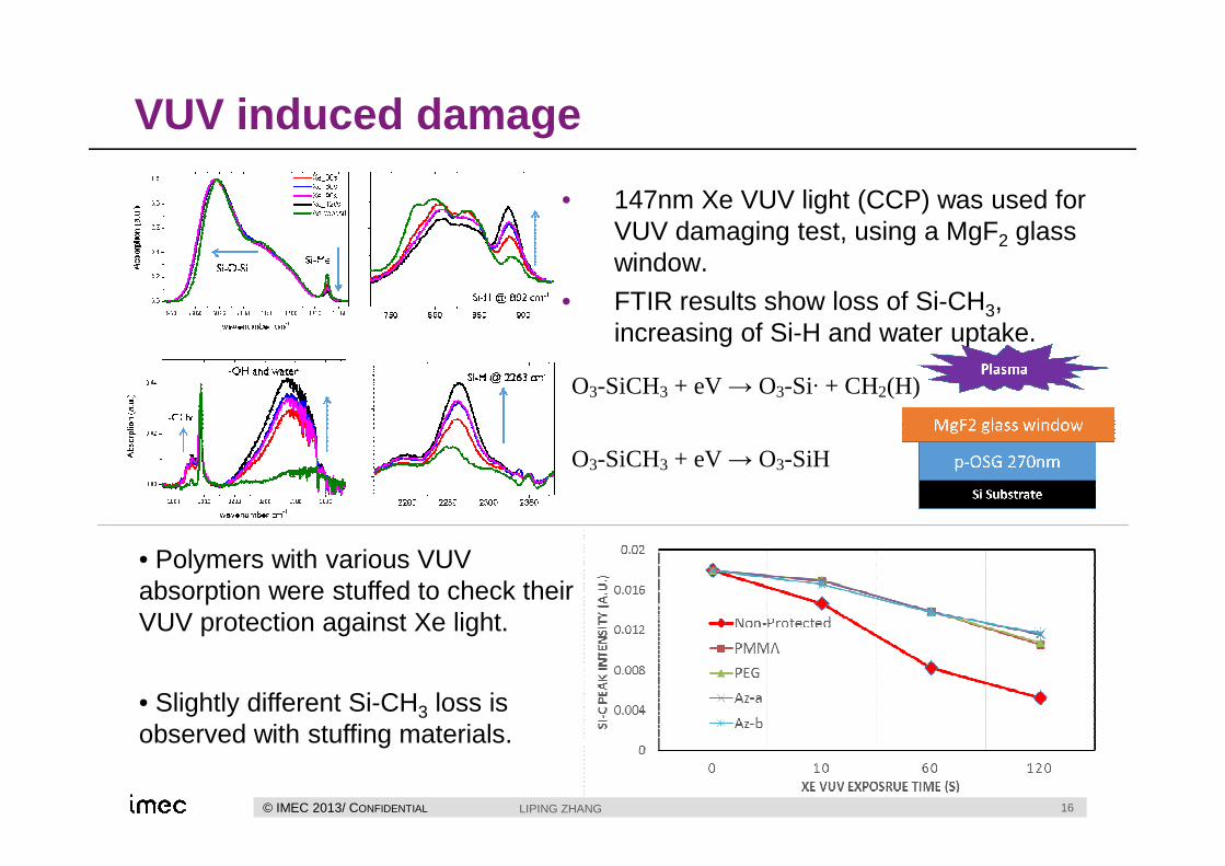
VUV induced damage
• Polymers with various VUV absorption were stuffed to check their VUV protection against Xe light.
• Slightly different Si-CH3 loss is observed with stuffing materials.
• 147nm Xe VUV light (CCP) was used for VUV damaging test, using a MgF2 glass window.
• FTIR results show loss of Si-CH3, increasing of Si-H and water uptake.
O3-SiCH3 + eV → O3-Si· + CH2(H)
O3-SiCH3 + eV → O3-SiH

17© IMEC 2013/ CONFIDENTIAL LIPING ZHANG
Outline
i. Cu/low-k interconnect and plasma induced damage
ii. Pore stuffing- Process flow
iii. Plasma Induced Damage
iv. Integration flow with Pore Stuffing
v. Summary
18© IMEC 2013/ CONFIDENTIAL LIPING ZHANG
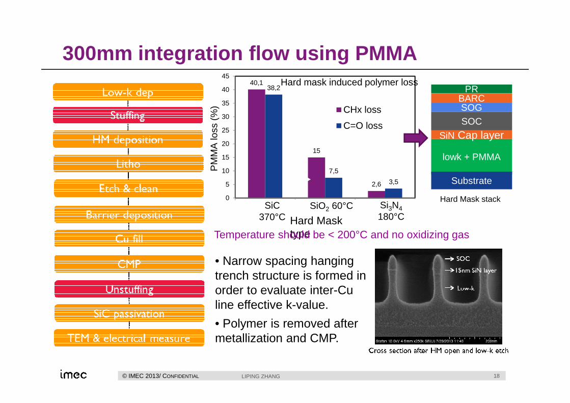
300mm integration flow using PMMA
Cu40,1
15
2,6
38,2
7,5
3,5
0
5
10
15
20
25
30
35
40
45
SiC SiO2 SiN
CHx loss
C=O loss
Hard Mask type
PM
MA
loss
(%
)
Hard mask induced polymer loss
lowk + PMMA
Substrate
SOC
SOGBARC
PR
SiN Cap layer
Hard Mask stackSiC
370°CSiO2 60°C Si3N4
180°C
Temperature should be < 200°C and no oxidizing gas
• Narrow spacing hanging trench structure is formed in order to evaluate inter-Cu line effective k-value.
• Polymer is removed after metallization and CMP.
19© IMEC 2013/ CONFIDENTIAL LIPING ZHANG
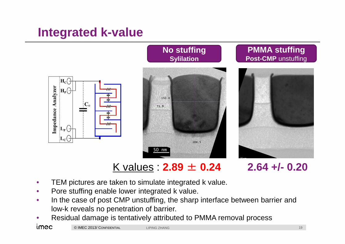
Integrated k -valueNo stuffing
SylilationPMMA stuffing
Post-CMP unstuffing
K values : 2.89 ± 0.24 2.64 +/- 0.20• TEM pictures are taken to simulate integrated k value.• Pore stuffing enable lower integrated k value.• In the case of post CMP unstuffing, the sharp interface between barrier and
low-k reveals no penetration of barrier.• Residual damage is tentatively attributed to PMMA removal process
20© IMEC 2013/ CONFIDENTIAL LIPING ZHANG
Outline
i. Cu/low-k interconnect and plasma induced damage
ii. Pore stuffing- Process flow
iii. Plasma Induced Damage
iv. Integration flow with Pore Stuffing
v. Summary
21© IMEC 2013/ CONFIDENTIAL LIPING ZHANG
Summary
• Following by surface active, spin-coating, thermal drive-in and surface cleaning, > 90% pore-stuffing of a 2.0 porous OSG was achieved.
• Reduced plasma induced damage is observed, based on various plasma tested on both blanket and patterned samples. VUV induced damage is also improved.
• Single damascene Cu/Low-k integration flow on 300mm substrate has been developed incorporating pore stuffing approach.


23© IMEC 2013/ CONFIDENTIAL LIPING ZHANG
Plasma induced damage
3800 3600 3400 3200 3000
0.00
0.02
0.04
0.06
0.08
0.10
Nor
mal
ized
abs
orpt
ion
(a.u
.)
Wavenumber cm-1
ArCF4_30s with PMMA ArCF4_30s without PMMA ArNF3_20s with PMMA ArNF3_20s without PMMA ArSF6_20s with PMMA ArSF6_20s without PMMA Pristine p-OSG
(a)
water and -OHCHx
1300 1200 1100 1000
0.0
0.2
0.4
0.6
0.8
1.0
Si-Me
Nor
mal
ized
abs
orpt
ion
(a.u
.)
Wavenumber cm-1
ArCF4_30s with PMMA ArCF4_30s without PMMA ArNF3_20s with PMMA ArNF3_20s without PMMA ArSF6_20s with PMMA ArSF6_20s without PMMA Pristine p-OSG
(b)
Si-O-Si
24© IMEC 2013/ CONFIDENTIAL LIPING ZHANG
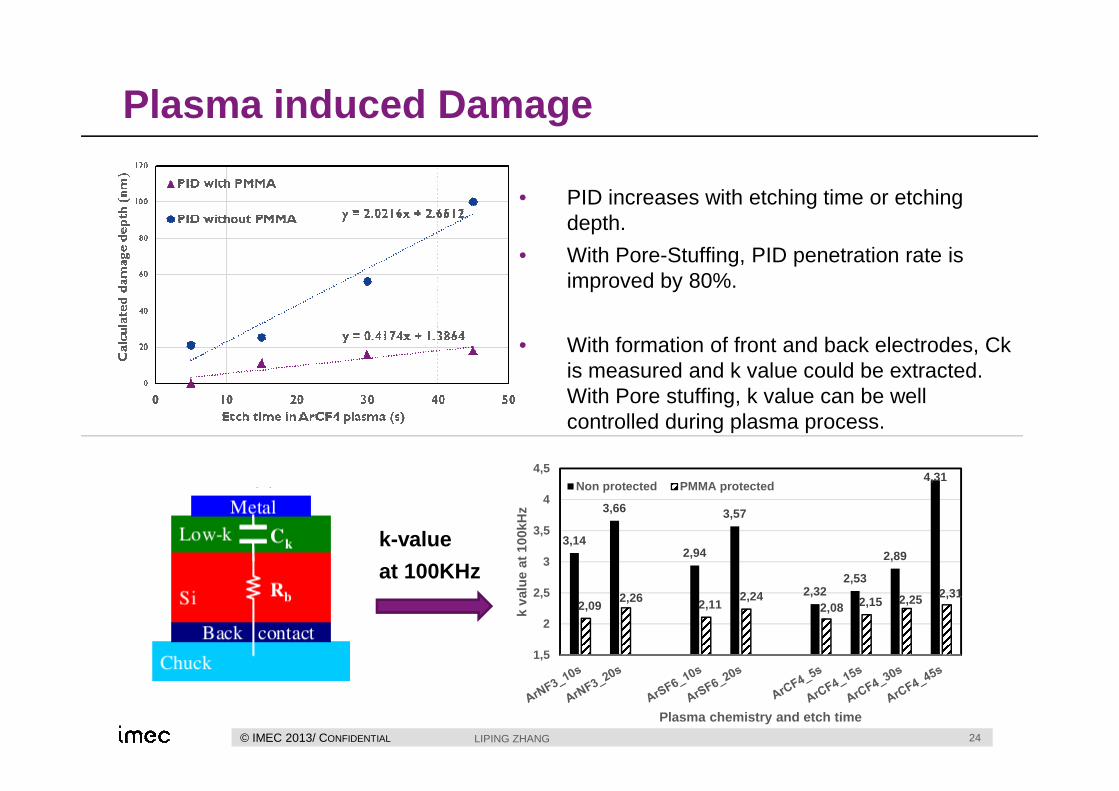
Plasma induced Damage
3,14
3,66
2,94
3,57
2,322,53
2,89
4,31
2,092,26 2,11
2,242,08 2,15 2,25 2,31
1,5
2
2,5
3
3,5
4
4,5
k va
lue
at 1
00kH
z
Plasma chemistry and etch time
Non protected PMMA protected
k-value
at 100KHz
• PID increases with etching time or etching depth.
• With Pore-Stuffing, PID penetration rate is improved by 80%.
• With formation of front and back electrodes, Ckis measured and k value could be extracted. With Pore stuffing, k value can be well controlled during plasma process.
Recommended