For more information visit: www.newmill.com 1
LONG-SPAN COMPOSITE SYSTEMS
Featuring Versa-Dek® Composite

2 © 2019 New Millennium Building Systems, LLC All rights reserved.For the complete selection of load tables, visit: www.newmill.com
LIABILITY STATEMENT
The data published in this design guide has been developed using recognized engineering principles and is intended for general information only. Although the data shown is believed to be accurate, New Millennium Building Systems does not assume any liability or obligation of any kind or nature arising from or related to the data provided herein and/or its use. Applicability of the products and the accuracy of the data should be assessed by a licensed professional engineer or architect to determine the suitability for the intended application. New Millennium Building Systems’ Standard Terms and Conditions shall supersede any statements to the contrary contained herein.
Lon
g-S
pa
n C
om
po
site
Sy
ste
ms
© 2019 New Millennium Building Systems, LLC All rights reserved.

3© 2019 New Millennium Building Systems, LLC All rights reserved. © 2019 New Millennium Building Systems, LLC All rights reserved. For the complete selection of load tables, visit: www.newmill.com
Table of Contents
System Overview
Introduction ............................................................................................................................. 4 – 5
Applications ............................................................................................................................ 6 – 9
Form and Function ...............................................................................................................10 – 11
Cantilevered Slabs .......................................................................................................................12
Versa-WedgeTM Hangers ...............................................................................................................13
Fire and Sound Performance ...............................................................................................14 – 15
System Integration ...............................................................................................................15 – 16
Installation ...........................................................................................................................17 – 18
Composite Slab Span Tables
Introduction to Composite Slab Design ........................................................................................19
Versa-Dek® 2.0 Composite..................................................................................................20 – 24
Versa-Dek® 3.5 LS Composite .............................................................................................25 – 29
Slab Beams ......................................................................................................................... 30 – 31
Lon
g-S
pa
n C
om
po
site S
yste
ms

4 © 2019 New Millennium Building Systems, LLC All rights reserved.For the complete selection of load tables, visit: www.newmill.com
Intr
od
uct
ion
S Y S T E M O V E R V I E W
Versa-Dek® Composite is versatile and efficient, providing many options for installation, integration, and finish.
Introduction
Only New Millennium offers you the most complete range of long-span composite systems engineered to optimize the cost and performance of multi-story building projects. System selection should be determined by span, load, fire, vibration and sound control requirements. Additional considerations include aesthetics and overall desired floor depth.
Versa-Dek® 2.0 Composite
Deep-Dek® Composite
Learn more about our long-span composite systemswww.newmill.com/longspan
24˝ Coverage
6˝
2˝
24˝ Coverage
8˝
213 ˝
Versa-Dek® 3.5 Composite
Composite Joists
LOW PROFILE, LONG SPANVersa-Dek® Composite is a versatile, long-span composite floor system. It’s ‘dovetail’ profiling keys to concrete to create a superior composite bond. Because more concrete is placed in the bottom of the deck, the total slab thickness needed to achieve fire ratings is the shallowest available.
Versa-Dek® Composite is ideal in multi-story residences demanding floor systems that are quiet, stable and cost-effective. Its head-of-wall fire rating eliminates the cost of placing expensive fire sealants in the deck flutes when set over CFS bearing walls. Additionally, Versa-Dek® Composite uniformly loads the top of cold-formed steel walls so distribution headers are not needed.
Versa-Dek® Composite combines cost-savings and competitive advantages applicable to any building market segment. These advantages include space optimization, acoustical control, MEP integration, and underside ceiling aesthetics when left exposed. An acoustical option brings the added advantage of sound dampening, without the addition of a drop ceiling.
Versa-Dek® Composite is formed from steel conforming to ASTM material specifications and corrosion protected with galvanized (zinc) coatings.

5© 2019 New Millennium Building Systems, LLC All rights reserved. © 2019 New Millennium Building Systems, LLC All rights reserved. For the complete selection of load tables, visit: www.newmill.com
Ad
van
tag
es
SPACE OPTIMIZATION• Low-profile slabs as thin as 4 inches maximize
ceiling height and reduce building height
• Spans up to 28' create open interior spaces
• Relocatable Versa-WedgeTM hangers suspend lighting and MEP components
AESTHETICS AND PERFORMANCE• Sleek, lineal plank ceiling aesthetic
• Galvanized coating weight and factory-applied coating options
• High-performance STC and IIC sound ratings
• Up to 3-hour fire endurance ratings
• UL approved 2-hour Head-of-Wall assembly
• Durable and dimensionally stable
EFFICIENT CONSTRUCTION• Integrates with any beam or wall construction
• Noncombustible — lower insurance premiums
• Not susceptible to termites, mold or dry-rot
• Traditional means and methods
• No specialized equipment or training
• Allows core drilling flexibility
APPROVALS AND STANDARDS• ICC ES Evaluation Reports ESR-2635
and ESR-3477
• Compliant with International Building Code (IBC)
• Designed in accordance with AISI S100 and ANSI/SDI C
S Y S T E M O V E R V I E W
Advantages

6 © 2019 New Millennium Building Systems, LLC All rights reserved.For the complete selection of load tables, visit: www.newmill.com
Ap
pli
cati
on
sS Y S T E M O V E R V I E W
Applications
Elan Heights Luxury Apartments | Houston, TXLow-profile Versa-Dek® Composite maximized living spaces with open spans. Reduced overall building height converts to cost savings for vertical building components (e.g. facades, MEP risers, etc.)
Managing floor height, fire and sound control, Versa-Dek® Composite is a low-profile floor solution suitable for any building market ... from multi-story residences to healthcare
facilities to academics and parking garages. It integrates with any structural system. Engineered floor openings, sleeves and hanging devices streamline MEP installations.

7© 2019 New Millennium Building Systems, LLC All rights reserved. © 2019 New Millennium Building Systems, LLC All rights reserved. For the complete selection of load tables, visit: www.newmill.com
Ap
plica
tion
sS Y S T E M O V E R V I E W
Sam Houston State University Piney Woods Residence Hall | Huntsville, TXThe unique composite bond between dovetail shaped Versa-Dek® Composite and concrete helped create long spans between the exterior and interior corridor walls.

8 © 2019 New Millennium Building Systems, LLC All rights reserved.For the complete selection of load tables, visit: www.newmill.com
Ap
pli
cati
on
sS Y S T E M O V E R V I E W
CityPlace in Springwoods Village | Spring, TXThis large residential development featured Versa-Dek® Composite in combination with prefabricated CFS bearing walls and upset steel beams. Integrated concrete balconies tie to the composite slabs.
Home2 Suites | Houston, TXVersa-Dek® Composite provides the shallowest unprotected fire ratings available. It also reduces story height while maximizing ceiling height and providing flexible MEP integration.
9© 2019 New Millennium Building Systems, LLC All rights reserved. © 2019 New Millennium Building Systems, LLC All rights reserved. For the complete selection of load tables, visit: www.newmill.com
Ap
plica
tion
sS Y S T E M O V E R V I E W
Seaport Channelside Parking Garage | Tampa, FLThis parking garage is a perfect example of the versatility of Versa-Dek® Composite: long spans, concrete beam integration, sloped ramping and durability with enhanced galvanized (zinc) coatings.
1011 M Street | Washington, DCBuilding in urban settings presents builders with unique challenges. Here, pre-fabricated CFS bearing walls combined with Versa-Dek® Composite to produce a noncombustible frame built with just-in-time deliveries.

10 © 2019 New Millennium Building Systems, LLC All rights reserved.For the complete selection of load tables, visit: www.newmill.com
Form
an
d F
un
ctio
n
24˝ Coverage
6˝
2˝
24˝ Coverage
8˝
213 ˝
S Y S T E M O V E R V I E W
Left architecturally exposed, Versa-Dek® provides a sleek lineal-plank aesthetic that can activate any space.
Form and Function
MAXIMIZED AESTHETICReduce costs by eliminating suspended ceilings. Exposed, the dovetail design provides a clean, lineal-plank aesthetic for office, retail and learning environments. Versa-Dek® Composite is non-combustible and is fire-resistance rated up to 3 hours without protective coverings such as gypsum and spray-on materials.
Versa-Dek® 2.0 Composite Versa-Dek® 3.5 Composite
24˝ Coverage
6˝
2˝
24˝ Coverage
8˝
213 ˝

11© 2019 New Millennium Building Systems, LLC All rights reserved. © 2019 New Millennium Building Systems, LLC All rights reserved. For the complete selection of load tables, visit: www.newmill.com
Form
an
d Fu
nctio
n
213 ˝
24˝ Coverage
8˝
24˝ Coverage
6˝
2˝
S Y S T E M O V E R V I E W
213 ˝
24˝ Coverage
8˝
ACOUSTICAL OPTIONSAcoustical treatments, consisting of sound insulation batts and perforated deck, combined with the deck’s shape contribute to noise control. Ambient noise is absorbed in the insulation and dissipates in the deck cavity.
24˝ Coverage
6˝
2˝
Versa-Dek® 2.0 Composite Acoustical Versa-Dek® 3.5 Composite Acoustical
A continuous channel caps and shields the insulation and perforations from wet concrete. Unsightly side-lap screw tips are hidden in the dovetail’s shadow. The exposed deck surfaces can be factory primed and readied for field applied finish paint.
Please visit www.newmill.com for load tables covering both Versa-Dek® 3.5 Composite Acoustical and Versa-Dek® 2.0 Composite Acoustical. Load tables in this brochure limited to non-acoustical deck.
Versa-Dek® 3.5 Composite Acoustical was designed into this 2-story, 12-classroom facility. Incorporating a modular kit delivery method, multi-functioning deck contributes to aesthetics, sound control and light reflectivity.
Ced
ar G
rove
, a P
roje
ct F
rog,
Inc.
pre
fabr
icat
ed b
uild
ing.
Pho
to c
ourte
sy o
f Pro
ject
Fro
g, In
c.

12 © 2019 New Millennium Building Systems, LLC All rights reserved.For the complete selection of load tables, visit: www.newmill.com
S Y S T E M O V E R V I E W
Ca
nti
leve
red
Sla
bs
Cantilevered formed-in-place balconies can be integrated into buildings with Versa-Dek® Composite slabs.
FORMED CONCRETE BALCONY SLAB
SLOPE AS REQUIRED
SEE TABLE FOR TOP REBAR SIZE AND SPACINGSKEW HOOK TO FIT
STEP DOWN AS REQUIREDWALL (BEYOND)
WALL HEADER
WALL (BEYOND)
THICKENED SLAB WIDTHAS REQUIRED BY DESIGN
SLAB REINFORCEMENT ASREQUIRED BY DESIGN
1 - #4 CONTINUOUSNOTES:1) SEE CANTILEVERED SLABS TABLE
NOTES FOR REBAR CONCRETECOVER REQUIREMENTS.
2) TERMINATION OF CANTILEVEREDSLAB REINFORCEMENT SHALL BEIN ACCORDANCE WITH ACI 318REQUIREMENTS.
3) SHRINKAGE AND TEMPERATUREREINFORCEMENT REQUIRED BYACI 318 IS NOT SHOWN.
SEE TABLE FOR MAXIMUM SPAN
SLAB DEPTHPER TABLE
Slab Depth(in.)
Maximum Span(ft)
Reinforcing Steel Required Over Supports
LL=60 psfSDL=5 psf
(102 psf LRFD factored load)
LL=100 psfSDL=5 psf
(166 psf LRFD factored load)
4.5 3’-9” #4@11 #4@11
5 4’-2” #4@11 #4@11
5.5 4’-7” #4@11 #4@11
6 5’-0” #4@11 #4@11
6.5 5’-5” #4@11 #4@11
7 5’-10” #4@11 #4@11
7.5 6’-3” #4@10 #4@10
NOTES: 1. Slab depth shown in the table is at the point of maximum moment.2. Table is based on f’c=4,000 psi concrete strength. 3. Table is based on 1-1/2” concrete cover for reinforcing bars over supports.4. Maximum span length is governed by ACI 318 span-to-depth requirements for cantilevered solid one-way slabs, L/h≥10.5. The rebar size and spacing are governed either by ACI 318 requirements on rebar spacing for crack control or by the ACI 318 requirements on minimum amount of reinforcement in flexural members. 6. Termination of cantilevered slab reinforcement shall be in accordance with ACI 318.7. Shrinkage and temperature reinforcement required by ACI 318 is not shown in section cut.
Cantilevered Slab Reinforcement Table
CANTILEVERED CONCRETE BALCONIES
FORMED CONCRETE BALCONY SLABFORMED CONCRETE BALCONY SLAB
SLOPE AS REQUIRED
SEE TABLE FOR TOP REBAR SIZE AND SPACINGSKEW HOOK TO FIT
STEP DOWN AS REQUIREDWALL (BEYOND)
WALL HEADER
WALL (BEYOND)
THICKENED SLAB WIDTHAS REQUIRED BY DESIGN
SLAB REINFORCEMENT ASREQUIRED BY DESIGN
1 - #4 CONTINUOUSNOTES:1) SEE CANTILEVERED SLABS TABLE
NOTES FOR REBAR CONCRETECOVER REQUIREMENTS.
2) TERMINATION OF CANTILEVEREDSLAB REINFORCEMENT SHALL BEIN ACCORDANCE WITH ACI 318REQUIREMENTS.
3) SHRINKAGE AND TEMPERATUREREINFORCEMENT REQUIRED BYACI 318 IS NOT SHOWN.
SEE TABLE FOR MAXIMUM SPAN
SLAB DEPTHPER TABLE

13© 2019 New Millennium Building Systems, LLC All rights reserved. © 2019 New Millennium Building Systems, LLC All rights reserved. For the complete selection of load tables, visit: www.newmill.com
SWIVEL LOOPHANGER
3/8” THREADED ROD
VERSA-WEDGETM
ICC ESR 3477
VERSA-DEK®
COMPOSITE3/8” HEX NUT3” WASHER
3/8” EYE BOLT
WIRE HANGER
S Y S T E M O V E R V I E W
VERSA-WEDGE™ HANGER SYSTEM
Versa-Dek® Steel Deck Panels Minimum Concrete Requirements1 Versa-WedgeTM Hanger
Type GageMaximum Panel Span (feet-inch)
Compressive Strength
(psi)
Slab Thickness2
(inch)
Allowable Tension Load
(lbf)
Deflection (inch) Hanger Type3
Versa-Dek® 2.0 Composite and Composite Acoustical
20 12’-4”
3500 4
314 0.04
VWT-20-250
VWT-20ES-250
VWT-20-375
VWT-20ES-375
18 14’-9” 308 0.01
16 14’-9” 308 0.01
20 15’-4”
3500 6
323 0.01
18 18’-5” 243 0.01
16 18’-5” 243 0.01
Versa-Dek® 3.5 Composite and Composite Acoustical
20 18’-0”
3500 5.5
691 0.01
VWT-35-375
VWT-35-500
18 18’-0” 691 0.01
16 19’-7” 934 0.01
20 20’-9”
3500 7.25
600 0.01
18 20’-9” 600 0.01
16 23’-9” 1069 0.01
Refer to ICC-ES ESR-3477, UL File EX16155 and UL File EX16155 for specific hanger application and design requirements, limitations, and load capacities. Proper loading sequence, including any seismic design considerations, shall be determined by the Structural Engineer of Record. Allowable tension loads, in consideration of deck span and gauge and slab properties, may be less than those shown in table. Materials other than the wedge component of the Versa-WedgeTM hanging system are not supplied by New Millennium Building Systems.
Versa-WedgeTM hangers are compatible with a wide range of components. Three commonly specified add-ons include threaded rod, swivel loop and eye bolt.
Versa-WedgeTM
Ve
rsa-W
ed
ge
TM Ha
ng
ers
Allowable Tension Loads for Versa-WedgeTM Hangers Installed in Ribs of Versa-Dek® Composite
1 Concrete can be either lightweight (110 pcf) or normal-weight (145 pcf) complying with IBC Chapter 19. 2 Concrete slab thickness is measured from the bottom of steel deck panel to top of concrete.3 -250, -375 and -500 designations denote 1/4", 3/8" and 1/2" rod diameters respectively.
Versa-Dek® Composite’s dovetail profile enables placement of the Versa-Wedge™ hanger system. It's an efficient, clean and economical way to suspend MEP services below the deck. The relocatable hangers are perfect for suspending signs and banners over multi-purpose spaces.
• Quick to install, adjust and relocate on site
• Easy to remove
• Reliably suspends ceilings, light fixtures, MEP and more
• Options for up to 1,000 pound load capacity

14 © 2019 New Millennium Building Systems, LLC All rights reserved.For the complete selection of load tables, visit: www.newmill.com
VERSA-DEK® COMPOSITE
VERSA-DEK® COMPOSITE-ACOUSTICAL
TOTAL SLABDEPTH
TOTAL SLABDEPTH
Fire
an
d S
ou
nd
Pe
rfo
rma
nce
S Y S T E M O V E R V I E W
Versa-Dek® Composite is UL fire rated for 1 to 3 hours, providing the thinnest slab depth requirement of any composite floor deck assembly.
Fire and Sound Performance
Versa-Dek® 2.0 Composite
Restrained Assembly Rating
Concrete Type
Total Slab Depth
1 NW 4"
1 LW 4"
1-1/2 NW 4-3/4"
2 NW 5-1/4"
2 SLW 5"
2 LW 4-1/2"
3 NW 6-3/4"
3 LW 5-1/4"
3 SLW 6"
UL Designs – D904, D917, D928, D961
VERSA-DEK® COMPOSITE
VERSA-DEK® COMPOSITE-ACOUSTICAL
TOTAL SLABDEPTH
TOTAL SLABDEPTH
Versa-Dek® 3.5 LS Composite
Restrained Assembly Rating
Concrete Type Total Slab Depth
1-1/2 NW 5-1/2"
1-1/2 LW 5-1/2"
2 NW 5-3/4"
2 LW 5-1/2"
3 NW 7-1/4"
3 LW 5-3/4"
UL Designs – D947, D964
Versa-Dek® 3.5 LS Composite Acoustical
Restrained Assembly Rating
Concrete Type Total Slab Depth
1-1/2 NW 6-3/4"
1-1/2 LW 5-3/4"
2 NW 7-1/4"
2 LW 6"
3 NW 8"
3 LW 6-15/16"
Versa-Dek® 2.0 Composite Acoustical
Restrained Assembly Rating
Concrete Type
Total Slab Depth
1 NW 5-1/2"
1 LW 4-5/8"
1-1/2 NW 6"
1-1/2 LW 5"
2 NW 6-1/2"
2 LW 5-1/4"
3 NW 7-1/4"
3 LW 6-7/16"
UL Design – D929 UL Designs – D947, D964
NW–Normal-Weight 147pcf SLW–Semi-Lightweight 130 pcf LW–Lightweight 112 pcfConcrete Type and Density
VERSA-DEK® COMPOSITE FLOOR SLABS
VERSA-DEK® COMPOSITE ACOUSTICAL FLOOR SLABS
VERSA-DEK®
- STAGGER DECK FLUTES EA. SIDE OF WALL
- STAGGER WIDTH= 1/2 PITCH OF RIB
CFS BEARING WALL
CL1/2
1/2
(1) END CLOSURECONCRETE & WWF
(ADDITIONAL REINFORCEMENT,
WHEN REQ'D, NOT SHOWN)
CLCLOPPOSING SIDE
OF WALL
HEAD-OF-WALL FIRE-SMOKE-SOUND BREAKREF: UL HW-S-0062 (2" VERSA-DEK COMPOSITE)
HEAD-OF-WALL FIRE-SMOKE-SOUND BREAK
VERSA-DEK® COMPOSITE HEAD-OF-WALL ASSEMBLIESOur industry exclusive UL tested Head-of-Wall design utilizes staggered deck flute installations to create continuous fire, smoke and sound breaks. Doing this eliminates placing costly (and messy) fire sealants in the open deck flutes.
Versa-Dek® 2.0 Composite
Restrained Assembly Rating Concrete Type Total Slab
Depth
1 & 2 NW or LW 4-1/2"
Versa-Dek® 3.5 LS Composite
Restrained Assembly Rating Concrete Type Total Slab
Depth
1 & 2 NW or LW 5-1/2"
UL Designs – HW-S-0062, HW-S-0127
UL Designs – HW-S-0127

15© 2019 New Millennium Building Systems, LLC All rights reserved. © 2019 New Millennium Building Systems, LLC All rights reserved. For the complete selection of load tables, visit: www.newmill.com
Fire a
nd
So
un
d Pe
rform
an
ce
ACOUSTICAL PERFORMANCE
Versa-Dek® Composite serves as the base system of sound- absorption-rated floor assemblies. Collateral flooring and ceiling treatments enhance the ratings.
STC refers to Sound Transmission Class. Generally, the STC rating reflects how well the floor assembly reduces airborne noise (energy loss) between spaces.
IIC refers to Impact Insulation Class. IIC rating measures the floor assembly's ability to isolate impact footfall noise between spaces.
Flooring and ceiling componentry type, arrangement and installation will influence acoustical performance. Decoupling, damping and flanking techniques should also be considered in noise reduction strategies.
ESTIMATED STC & IIC RATINGS OF VERSA-DEK COMPOSITE FLOOR ASSEMBLIES
Notes:1. Consult component manufacturers for information regarding sizes, types, spacings and/orinstallation requirements for all collateral flooring and ceiling materials.2. STC values for base systems (bare slabs) were calculated as STC=0.1304*W+43.48 in accordancewith Section 9.2 of PCI Design Handbook, 6th Edition.3. IIC values for base systems (bare slabs) were calculated as IIC=(19.4+0.5*h)+(0.02+0.0036*h)*W.The formula was derived from the data published in Section 9.2 of PCI Design Handbook, 6th Edition.4. Reference Architectural Acoustics handbook by David Egan for acoustical enhancements providedby floors and ceiling materials.
®
STEEL BEAM
System Integration – Construction Details
EXTERIOR BEAM
CURTAINWALL
POURSTOP
WWF CONCRETE
VERSA-DEK® COMPOSITE
INTERIOR BEAM
VERSA-DEK® COMPOSITE
WWF
CONCRETE
SHEAR STUD- CONSIDER DECK PITCH
FOR STUD DESIGN: 2" VDC = 6"
3.5" VDC = 8"
INT. BEAM @ CHANGE IN DECK DIRECTION
VERSA-DEK® COMPOSITE
END CLOSUREWWF
Z-CLOSURE
CONCRETE
EXTERIOR BEAM INTERIOR BEAM INTERIOR BEAM @ CHANGE IN DECK DIRECTION
CORRIDOR HEADER BEAM
CONCRETE
WT BEAM
WWFEND
CLOSURE
VERSA-DEK®
COMPOSITE GYPSUMBOARD
STUD FURRINGOVER CORRIDOR
M/E/P PLENUM
VERSA-DEK® COMPOSITEBEAM
- HOLE-PUNCH WEB FORREBAR PASSAGE
UPSET BEAM @ MULTI-SPAN SLAB
WWF
CONCRETEREBAR FOR MULTI-SPAN SLAB
VERSA-DEK® COMPOSITE
WWF CONCRETE
BEAM
UPSET BEAM @ SINGLE SPAN SLABCORRIDOR HEADER BEAM UPSET BEAM @ MULTI-SPAN SLAB UPSET BEAM @ SINGLE-SPAN SLAB
S Y S T E M O V E R V I E W
SHEAR STUD- CONSIDER DECK PITCH
FOR STUD DESIGN: VERSA-DEK® 2.0 COMPOSITE = 6"VERSA-DEK® 3.5 COMPOSITE = 8"

16 © 2019 New Millennium Building Systems, LLC All rights reserved.For the complete selection of load tables, visit: www.newmill.com
BEARING WALL
System Integration – Construction Details
REINFORCEMENT FOR SLAB CONTINUITY
REBAR LENGTH =0.3 X SPAN LENGTH
REBAR LENGTH =0.3 X SPAN LENGTH
FACE OF WALL
REBAR FOR SLAB CONTINUITY (NEGATIVEBENDING FORCES)
- WHEN REQ'D BY DESIGN- T.O. REBAR MIN. 3
4" BELOW TOP OF SLAB(TYP. INTERIOR APPLICATIONS)
INTERIOR @ CHANGE IN DECK DIRECTION
CMU WALL
VERSA-DEK® COMPOSITEEND CLOSURE
'ZEE' CLOSURE
INTERIOR @ CHANGE IN DECK DIRECTION
CFS WALL
VERSA-DEK® COMPOSITE- STAGGER FLUTES FOR
HEAD-OF-WALL FIRE BREAK
REBAR FOR SLABCONTINUITY(WHEN REQ'D BYDESIGN)
CONCRETE
WWF
END CLOSURE
INTERIOR CFS BRG. WALLINTERIOR CFS BEARING WALL
CONCRETEWWF
FACE OF CMU & CONCRETE CORE WALLS
CMU WALL
VERSA-DEK® COMPOSITE
LEDGER ANGLE- ANCHOR TO CMU WALLAS REQ'D BY DESIGN
CONCRETE WALL
VERSA-DEK® COMPOSITE
LEDGER ANGLE- ANCHOR TO CMU WALLAS REQ'D BY DESIGN
FACE OF CMU & CONCRETE CORE WALLS
REINFORCEMENT FOR SLAB CONTINUITY
Sy
ste
m I
nte
gra
tio
nS Y S T E M O V E R V I E W
EXT. CFS BRG WALL W/BRICK SHELF
HEAD-OF-WALL FIRE BREAK
POUR STOP
EXTERIOR CFS BRG WALL
VERSA-DEK® COMPOSITE
WWF
CONCRETE
CFS WALL
EXTERIOR CFS BRG WALL
SLAB REINFORCEMENT
Contact New Millennium for suggested details of slab reinforcement surrounding floor openings and penetrations along with other project specific design needs.
STEEL ANGLES& REINFORCEMENT
- BY DESIGN
EXT. CFS BRG WALL W/ BRICK SHELF
VERSA-DEK® COMPOSITE
WWFCONCRETE
CFS WALL
CONCRETE WALL
Versa-Dek®COMPOSITE
LEDGER ANGLE- ANCHOR TO CONCRETE WALL AS REQ'D BY DESIGN
CONCRETEWWF
FACE OF CMU & CONCRETE CORE WALLS
CMU WALL
VERSA-DEK® COMPOSITE
LEDGER ANGLE- ANCHOR TO CMU WALLAS REQ'D BY DESIGN
CONCRETE WALL
VERSA-DEK® COMPOSITE
LEDGER ANGLE- ANCHOR TO CMU WALLAS REQ'D BY DESIGN
CONCRETE CONSTRUCTION JOINT

17© 2019 New Millennium Building Systems, LLC All rights reserved. © 2019 New Millennium Building Systems, LLC All rights reserved. For the complete selection of load tables, visit: www.newmill.com
Versa-Dek® Composite installation employs traditional means, methods and workforce. Deck is delivered bundled in cut-to-length pieces corresponding to deck-placement drawings prepared by New Millennium.
Depending on span, construction loading needs and deck type, temporary shoring is placed between supports prior to installation. Versa-Dek® 2.0 Composite utilized in 2-hour rated slab depths, is shored at intervals ranging between 7.5' and 9' on center depending on deck and concrete properties. Versa-Dek® 3.5 Composite can be designed unshored up to 16' utilizing similarly rated slabs.
When shoring is required by design, the contractor shall employ the services of a Shoring Engineer to evaluate the shoring system selection and installation sequencing.
Upon placement and alignment, the deck is attached to the supports with welds, screws or powder actuated fasteners depending on support type and need. Deck side laps are then periodically screwed.
When placed over CFS bearing walls, the deck is typically installed in single-span lengths and the fluted ends are staggered to each side of the wall. Doing so creates a UL approved Head-of-Wall assembly that blocks fire, smoke and sound between living compartments.
Prior to placing concrete, slab-reinforcing steel is set over the deck. Welded wire mesh is utilized to control temperature- shrinkage. Micro-synthetic fibers may also be considered. Multi-span slabs, generally limited to long-span and/or high-load designs, are tied with rebar placed over supports. Rebar is also placed at slab openings, over wall distribution headers and boundary conditions depending on need.
The concrete topping is monolithically cast and finished using common equipment and techniques. The topping, utilizing either light- or normal-weight concrete finishes flat without camber. Minor slab deflection, however, is common upon release of shoring. Total slab depth is influenced by structural and fire-separation need.
Integrated slab-beams can be used to replace bearing walls and frame large floor openings. The plywood formed beams typically match the depth of the composite slab beyond the beam. Dropped slab beams may also be utilized in long- span applications. Upset, low profile steel beams may also be considered.
BUILD ASSISTANCENew Millennium Building Systems assists builders through the bid and installation phases.
Material estimates and pricing are offered at any stage of the project.
In addition to the Versa-Dek® panel materials, New Millennium offers accessories to complete the installation. They include gage steel pour stop at boundary conditions, end- and side-closures and screw fasteners.
Our estimates do not include accessories to form MEP openings and holes. Additionally, concrete, slab reinforcement and shoring materials are the responsibility of others.
Upon award, we can provide necessary approval and field-use deck placement drawings.
Project management services help match manufacturing and delivery schedules with customer needs. Field seminars to familiarize installers with specified floor system are also available upon request.
Insta
llatio
nS Y S T E M O V E R V I E W
Deck installation, slab reinforcement placement and concrete casting incorporate traditional equipment and methods.
Installation

18 © 2019 New Millennium Building Systems, LLC All rights reserved.For the complete selection of load tables, visit: www.newmill.com
Inst
all
ati
on
MEP INTEGRATIONPreset pipe sleeves help streamline MEP service installations, while deck inserts and drilled-in threaded rod hangers are used to suspend services below the floor.
MEP integration is streamlined with preset and built-in features.
Versa-Dek® Composite makes engineered penetration of vent or sewage stacks readily achievable.
S Y S T E M O V E R V I E W

19© 2019 New Millennium Building Systems, LLC All rights reserved. © 2019 New Millennium Building Systems, LLC All rights reserved. For the complete selection of load tables, visit: www.newmill.com
According to the Steel Deck Institute Code of Standard Practice, composite slab design is the responsibility of the Project Structural Engineer of Record.
LOAD TABLESTo assist designers, New Millennium offers Versa-Dek® Composite slab design tables. Tables include:
• Deck descriptions, section properties and strengths
• Maximum allowable spans based on service and construction stage loading
• Maximum allowable superimposed uniform loads based on given span lengths
• Suggested reinforcing steel over supports for continuous spans based on given superimposed load combinations
The tables cover Versa-Dek® 2.0 Composite and Versa-Dek® 3.5 Composite, in separate sections, over a range of slab depths. Both normal-weight (145 pcf) and lightweight (110 pcf) concrete density of 4,000 psi strength are provided. Service stage instantaneous deflection limits are based on L/240 total load and L/360 live load. The maximum span and uniform load tables are applicable to single-span slabs and continuous slabs with approximately equal span lengths. Upon request, New Millennium can prepare project specific tables based on alternative criteria.
DESIGN GUIDE FOR VERSA-DEK® COMPOSITEPlease visit the New Millennium website for expanded load table coverage. In addition to tables found in this brochure, the guide includes:
• Composite slab properties (moment of inertia (MOI), positive moment capacity and one-way shear capacities)
• Factored shear bond strength of composite slabs
• Allowable load and maximum span tables accounting for long-term slab deflection
• Maximum design negative moment capacity defined by rebar type and spacing, slab depth and concrete strength
Versa-Dek® 2.0 Composite tables cover 3,000, 4,000 and 5,000 psi concrete strengths while Versa-Dek® 3.5 Composite tables cover 4,000, 5,000 and 6,000 psi concrete.
CUSTOM SLAB DESIGNSComposite slab property tables are used for designs not conforming to the limiting criteria of allowable load tables. Examples include continuous slabs with unequal spans or loading, concentrated load conditions, etc. In these and other cases, use a standard beam analysis program to determine
strength and stiffness needs based on defined load combinations and patterns. The moment, shear and stiffness requirements obtained from that analysis are then compared to the composite slab properties. Slab deflections, determined using the average of cracked and uncracked MOI as published in the property tables, shall can be compared against the required stiffness.
CONSTRUCTION STAGE (NON-COMPOSITE) DECK DESIGNMaximum unshored clear span values were based on ANSI/SDI C-2017 for the design of deck as a form supporting the weight of deck and fluid concrete plus the worse case effect of either 20 psf uniform or 150 lb. concentrated (on a 1' width) construction live load. Construction stage deck deflection is limited to the lessor of L/180 or 3/4".
The construction live loads stated above are considered adequate for concrete transport and placement by hose and concrete finishing using hand tools.
Contact New Millennium for maximum unshored clear spans based on construction live loads greater and deflection limits more restrictive than those stated above.
Co
mp
osite
Sla
b D
esig
nS Y S T E M O V E R V I E W
Composite Slab Design

20 © 2019 New Millennium Building Systems, LLC All rights reserved.For the complete selection of load tables, visit: www.newmill.com
Co
mp
osi
te S
pa
n T
ab
les
Versa-Dek® 2.0 LS ES Composite 4000 PSI NORMAL-WEIGHT CONCRETE
Versa-Dek Composite 2LS ESDECK PROPERTIES
Gage Thickness(in.)
Coverage(in.)
Weight(psf) Fy (ksi) As
(in.2/ft)ID (in.4/ft) Sp
(in.3/ft)Sn
(in.3/ft)fVn
(lb/ft)fRbe
(lb/ft)fRbi
(lb/ft)single multi22 0.0295 24 2.25 40 0.660 0.417 0.417 0.304 0.309 4594 999 190820 0.0358 24 2.72 40 0.800 0.505 0.506 0.386 0.379 5548 1427 271718 0.0474 24 3.60 40 1.058 0.667 0.667 0.510 0.507 7280 2389 453316 0.0598 24 4.53 40 1.332 0.838 0.838 0.640 0.640 9096 3657 6922
Fy is steel yield stress; As is area of deck; ID is deck moment of inertia for deflection calculations; Sp and Sn are deck section moduli in positive and negative bending, respectively; fVn isdesign shear strength of deck; fRbe and fRbi are design web crippling strengths of deck for end and interior bearing, respectively.
MAXIMUM ALLOWABLE SPANS - NORMAL WEIGHT CONCRETE (145 PCF), f'c=4000 PSI
Total SlabDepth(in.)
Service Stage Construction StageSimple Spans (ft-in.) Continuous Spans (ft-in.) Maximum Unshored Clear
Spans (ft-in.)LL=40 psfSDL=20 psf
LL=80 psfSDL=5 psf
LL=100 psfSDL=5 psf
LL=40 psf; SDL=20 psf LL=80 psf; SDL=5 psf LL=100 psf; SDL=5 psfinterior span end span interior span end span interior span end span single double triple
22 GA Deck4 13' - 10" 12' - 11" 12' - 4" 20' - 6" 17' - 1" 17' - 10" 15' - 11" 16' - 6" 15' - 2" 7' - 6" 8' - 7" 8' - 10"5 16' - 5" 15' - 5" 14' - 9" 24' - 4" 20' - 3" 22' - 10" 19' - 0" 21' - 4" 18' - 2" 6' - 11" 7' - 10" 8' - 1"
5.25 17' - 0" 16' - 0" 15' - 4" 25' - 3" 21' - 0" 23' - 8" 19' - 9" 22' - 6" 18' - 11" 6' - 9" 7' - 8" 8' - 0"5.5 17' - 7" 16' - 7" 15' - 11" 26' - 2" 21' - 9" 24' - 7" 20' - 6" 23' - 5" 19' - 6" 6' - 8" 7' - 7" 7' - 10"6 18' - 10" 17' - 9" 17' - 0" 27' - 11" 23' - 3" 26' - 1" 21' - 8" 24' - 4" 20' - 3" 6' - 5" 7' - 3" 7' - 6"
6.5 19' - 11" 18' - 10" 17' - 10" 29' - 7" 24' - 8" 26' - 10" 22' - 5" 25' - 2" 20' - 11" 6' - 3" 7' - 1" 7' - 3"7 21' - 1" 19' - 8" 18' - 5" 30' - 10" 25' - 8" 27' - 7" 23' - 0" 25' - 11" 21' - 7" 6' - 0" 6' - 10" 7' - 1"
7.5 22' - 2" 20' - 1" 18' - 11" 31' - 6" 26' - 3" 28' - 4" 23' - 7" 26' - 7" 22' - 2" 5' - 10" 6' - 8" 6' - 10"8 22' - 10" 20' - 7" 19' - 4" 32' - 1" 26' - 9" 28' - 11" 24' - 1" 27' - 3" 22' - 8" 5' - 9" 6' - 5" 6' - 8"
20 GA Deck4 14' - 2" 13' - 2" 12' - 7" 20' - 6" 17' - 6" 17' - 10" 16' - 3" 16' - 6" 15' - 6" 8' - 9" 9' - 6" 9' - 9"5 16' - 9" 15' - 8" 15' - 0" 24' - 10" 20' - 8" 22' - 11" 19' - 5" 21' - 4" 18' - 7" 8' - 0" 8' - 8" 9' - 0"
5.25 17' - 4" 16' - 4" 15' - 8" 25' - 9" 21' - 5" 24' - 2" 20' - 2" 22' - 6" 19' - 4" 7' - 10" 8' - 6" 8' - 10"5.5 18' - 0" 16' - 11" 16' - 3" 26' - 8" 22' - 3" 25' - 1" 20' - 11" 23' - 7" 20' - 1" 7' - 8" 8' - 4" 8' - 8"6 19' - 2" 18' - 1" 17' - 4" 28' - 5" 23' - 8" 26' - 10" 22' - 4" 25' - 9" 21' - 6" 7' - 5" 8' - 1" 8' - 4"
6.5 20' - 4" 19' - 3" 18' - 6" 30' - 2" 25' - 2" 28' - 6" 23' - 9" 27' - 5" 22' - 10" 7' - 2" 7' - 9" 8' - 1"7 21' - 6" 20' - 4" 19' - 7" 31' - 10" 26' - 6" 30' - 2" 25' - 2" 28' - 4" 23' - 7" 6' - 11" 7' - 7" 7' - 10"
7.5 22' - 7" 21' - 5" 20' - 8" 33' - 6" 27' - 11" 31' - 0" 25' - 10" 29' - 1" 24' - 3" 6' - 9" 7' - 4" 7' - 7"8 23' - 8" 22' - 6" 21' - 2" 35' - 1" 29' - 3" 31' - 8" 26' - 5" 29' - 10" 24' - 10" 6' - 7" 7' - 2" 7' - 4"
18 GA Deck4 14' - 7" 13' - 7" 13' - 0" 20' - 5" 18' - 1" 17' - 9" 16' - 10" 16' - 6" 15' - 7" 10' - 4" 10' - 11" 11' - 3"5 17' - 3" 16' - 3" 15' - 6" 25' - 7" 21' - 4" 22' - 10" 20' - 0" 21' - 3" 19' - 2" 9' - 5" 10' - 0" 10' - 4"
5.25 17' - 11" 16' - 10" 16' - 2" 26' - 7" 22' - 2" 24' - 1" 20' - 10" 22' - 5" 19' - 11" 9' - 3" 9' - 10" 10' - 2"5.5 18' - 6" 17' - 5" 16' - 9" 27' - 6" 22' - 11" 25' - 3" 21' - 7" 23' - 7" 20' - 8" 9' - 0" 9' - 7" 9' - 11"6 19' - 9" 18' - 8" 17' - 11" 29' - 4" 24' - 5" 27' - 7" 23' - 1" 25' - 10" 22' - 2" 8' - 9" 9' - 3" 9' - 7"
6.5 21' - 0" 19' - 10" 19' - 1" 31' - 1" 25' - 11" 29' - 5" 24' - 6" 28' - 0" 23' - 7" 8' - 5" 9' - 0" 9' - 3"7 22' - 1" 21' - 0" 20' - 2" 32' - 10" 27' - 4" 31' - 1" 25' - 11" 29' - 11" 25' - 0" 8' - 2" 8' - 9" 9' - 0"
7.5 23' - 3" 22' - 1" 21' - 4" 34' - 6" 28' - 9" 32' - 9" 27' - 3" 31' - 7" 26' - 4" 7' - 11" 8' - 6" 8' - 9"8 24' - 4" 23' - 2" 22' - 4" 36' - 1" 30' - 1" 34' - 4" 28' - 8" 33' - 2" 27' - 8" 7' - 8" 8' - 3" 8' - 6"
16 GA Deck4 15' - 0" 14' - 0" 13' - 5" 20' - 4" 18' - 7" 17' - 9" 16' - 10" 16' - 5" 15' - 7" 11' - 5" 12' - 2" 12' - 7"5 17' - 9" 16' - 8" 16' - 0" 25' - 10" 21' - 11" 22' - 10" 20' - 7" 21' - 3" 19' - 9" 10' - 8" 11' - 2" 11' - 7"
5.25 18' - 5" 17' - 4" 16' - 7" 27' - 2" 22' - 9" 24' - 0" 21' - 5" 22' - 5" 20' - 6" 10' - 6" 11' - 0" 11' - 4"5.5 19' - 1" 17' - 11" 17' - 2" 28' - 3" 23' - 6" 25' - 3" 22' - 2" 23' - 6" 21' - 3" 10' - 3" 10' - 9" 11' - 2"6 20' - 4" 19' - 2" 18' - 5" 30' - 1" 25' - 1" 27' - 7" 23' - 8" 25' - 9" 22' - 9" 9' - 11" 10' - 5" 10' - 9"
6.5 21' - 6" 20' - 4" 19' - 7" 31' - 11" 26' - 7" 29' - 10" 25' - 2" 27' - 11" 24' - 3" 9' - 7" 10' - 1" 10' - 5"7 22' - 8" 21' - 6" 20' - 9" 33' - 8" 28' - 1" 31' - 11" 26' - 7" 30' - 1" 25' - 8" 9' - 3" 9' - 9" 10' - 1"
7.5 23' - 10" 22' - 8" 21' - 10" 35' - 4" 29' - 6" 33' - 7" 28' - 0" 32' - 1" 27' - 0" 9' - 0" 9' - 6" 9' - 9"8 25' - 0" 23' - 9" 22' - 11" 37' - 0" 30' - 10" 35' - 3" 29' - 4" 34' - 1" 28' - 4" 8' - 9" 9' - 3" 9' - 6"
NOTES:1. Deck section properties are calculated in accordance with AISI S100-07. 2. Maximum clear spans without shoring and design web crippling strengths are based on deck bearing of 1.5" at end supports and 3" at interior supports.3. Maximum construction clear spans are based on ANSI/SDI C-2017 design criteria. For maximum clear spans based on different criteria contact New Millennium. 4. Composite slab service stage calculations are based on ANSI/SDI C-2017 and ASCE 3-91. 5. The service stage spans are based on the instantaneous deflection limit of L/360 under total load. Contact New Millennium for maximum span based on alternative deflection criteria.6. Long-term deflection has not been taken into consideration. Visit newmill.com for load tables that consider long-term deflection.7. Temperature and shrinkage reinforcement in accordance with ANSI/SDI C-2017 shall be provided in the slab.8. Negative moment (top) reinforcement is required over supports of continuous spans. See table entitled Suggested Reinforcing Steel Over Supports for Continuous Slabs (page 23) for details.9. Continuous spans should be approximately equal with the span length difference not exceeding 20%. See Custom Slab Designs discussion (page 19) for guidance on unequal span design.
DECK DESCRIPTION SECTION PROPERTIES STRENGTHS (BARE DECK)
MAXIMUM ALLOWABLE SPANS (SERVICE AND CONSTRUCTION STAGE) – NORMAL-WEIGHT CONCRETE (145 PCF), f'c = 4000 PSI
NOTES
24˝ Coverage
6˝
2˝
24˝ Coverage
6˝
2˝

21© 2019 New Millennium Building Systems, LLC All rights reserved. © 2019 New Millennium Building Systems, LLC All rights reserved. For the complete selection of load tables, visit: www.newmill.com
Co
mp
osite
Sp
an
Tab
les
Versa-Dek® 2.0 LS ES Composite 4000 PSI LIGHTWEIGHT CONCRETE
Versa-Dek Composite 2LS ESDECK PROPERTIES
Gage Thickness(in.)
Coverage(in.)
Weight(psf) Fy (ksi) As
(in.2/ft)ID (in.4/ft) Sp
(in.3/ft)Sn
(in.3/ft)fVn
(lb/ft)fRbe
(lb/ft)fRbi
(lb/ft)single multi22 0.0295 24 2.25 40 0.660 0.417 0.417 0.304 0.309 4594 999 190820 0.0358 24 2.72 40 0.800 0.505 0.506 0.386 0.379 5548 1427 271718 0.0474 24 3.60 40 1.058 0.667 0.667 0.510 0.507 7280 2389 453316 0.0598 24 4.53 40 1.332 0.838 0.838 0.640 0.640 9096 3657 6922
Fy is steel yield stress; As is area of deck; ID is deck moment of inertia for deflection calculations; Sp and Sn are deck section moduli in positive and negative bending, respectively; fVn isdesign shear strength of deck; fRbe and fRbi are design web crippling strengths of deck for end and interior bearing, respectively.
MAXIMUM ALLOWABLE SPANS - LIGHTWEIGHT CONCRETE (110 PCF), f'c=4000 PSI - LRFD
Total SlabDepth(in.)
Service Stage Construction StageSimple Spans (ft-in.) Continuous Spans (ft-in.) Maximum Unshored Clear
Spans (ft-in.)LL=40 psfSDL=20 psf
LL=80 psfSDL=5 psf
LL=100 psfSDL=5 psf
LL=40 psf; SDL=20 psf LL=80 psf; SDL=5 psf LL=100 psf; SDL=5 psfinterior span end span interior span end span interior span end span single double triple
22 GA Deck4 13' - 2" 12' - 2" 11' - 7" 19' - 6" 16' - 3" 18' - 0" 15' - 0" 17' - 0" 14' - 3" 8' - 3" 9' - 5" 9' - 9"5 15' - 7" 14' - 6" 13' - 10" 23' - 2" 19' - 3" 21' - 7" 18' - 0" 20' - 7" 17' - 1" 7' - 7" 8' - 8" 9' - 0"
5.25 16' - 2" 15' - 1" 14' - 5" 24' - 0" 20' - 0" 22' - 5" 18' - 8" 21' - 5" 17' - 10" 7' - 6" 8' - 6" 8' - 10"5.5 16' - 10" 15' - 8" 15' - 0" 24' - 11" 20' - 9" 23' - 3" 19' - 5" 22' - 2" 18' - 6" 7' - 4" 8' - 4" 8' - 8"6 17' - 11" 16' - 10" 16' - 1" 26' - 7" 22' - 2" 24' - 11" 20' - 9" 23' - 10" 19' - 10" 7' - 1" 8' - 1" 8' - 4"
6.5 19' - 1" 17' - 11" 17' - 1" 28' - 3" 23' - 7" 26' - 6" 22' - 1" 25' - 5" 21' - 2" 6' - 11" 7' - 10" 8' - 1"7 20' - 2" 18' - 11" 18' - 2" 29' - 11" 24' - 11" 28' - 1" 23' - 5" 26' - 11" 22' - 5" 6' - 8" 7' - 7" 7' - 10"
7.5 21' - 3" 20' - 0" 19' - 2" 31' - 6" 26' - 3" 29' - 8" 24' - 8" 27' - 11" 23' - 3" 6' - 6" 7' - 5" 7' - 8"8 22' - 3" 21' - 0" 20' - 2" 33' - 0" 27' - 6" 30' - 8" 25' - 6" 28' - 8" 23' - 10" 6' - 4" 7' - 3" 7' - 6"
20 GA Deck4 13' - 5" 12' - 5" 11' - 10" 19' - 11" 16' - 7" 18' - 5" 15' - 5" 17' - 0" 14' - 7" 9' - 7" 10' - 5" 10' - 9"5 16' - 0" 14' - 11" 14' - 2" 23' - 8" 19' - 9" 22' - 1" 18' - 5" 21' - 0" 17' - 6" 8' - 10" 9' - 7" 9' - 11"
5.25 16' - 7" 15' - 6" 14' - 9" 24' - 7" 20' - 6" 22' - 11" 19' - 1" 21' - 11" 18' - 3" 8' - 8" 9' - 5" 9' - 9"5.5 17' - 2" 16' - 1" 15' - 4" 25' - 6" 21' - 3" 23' - 9" 19' - 10" 22' - 9" 18' - 11" 8' - 6" 9' - 3" 9' - 7"6 18' - 4" 17' - 2" 16' - 5" 27' - 3" 22' - 8" 25' - 6" 21' - 3" 24' - 4" 20' - 4" 8' - 3" 8' - 11" 9' - 3"
6.5 19' - 6" 18' - 3" 17' - 6" 28' - 11" 24' - 1" 27' - 1" 22' - 7" 26' - 0" 21' - 8" 8' - 0" 8' - 8" 9' - 0"7 20' - 7" 19' - 4" 18' - 7" 30' - 7" 25' - 5" 28' - 9" 23' - 11" 27' - 6" 22' - 11" 7' - 9" 8' - 5" 8' - 8"
7.5 21' - 8" 20' - 5" 19' - 7" 32' - 2" 26' - 9" 30' - 3" 25' - 3" 29' - 1" 24' - 3" 7' - 6" 8' - 2" 8' - 6"8 22' - 9" 21' - 5" 20' - 7" 33' - 8" 28' - 1" 31' - 10" 26' - 6" 30' - 7" 25' - 6" 7' - 4" 8' - 0" 8' - 3"
18 GA Deck4 13' - 11" 12' - 11" 12' - 3" 20' - 8" 17' - 2" 18' - 5" 15' - 11" 16' - 11" 15' - 2" 11' - 5" 11' - 11" 12' - 4"5 16' - 6" 15' - 5" 14' - 8" 24' - 6" 20' - 5" 22' - 10" 19' - 0" 21' - 9" 18' - 2" 10' - 5" 11' - 0" 11' - 5"
5.25 17' - 2" 16' - 0" 15' - 3" 25' - 5" 21' - 2" 23' - 9" 19' - 9" 22' - 8" 18' - 11" 10' - 3" 10' - 10" 11' - 2"5.5 17' - 9" 16' - 7" 15' - 10" 26' - 4" 21' - 11" 24' - 7" 20' - 6" 23' - 6" 19' - 7" 10' - 0" 10' - 8" 11' - 0"6 19' - 0" 17' - 9" 17' - 0" 28' - 2" 23' - 5" 26' - 4" 22' - 0" 25' - 3" 21' - 0" 9' - 8" 10' - 3" 10' - 8"
6.5 20' - 2" 18' - 11" 18' - 1" 29' - 11" 24' - 11" 28' - 1" 23' - 4" 26' - 10" 22' - 5" 9' - 5" 10' - 0" 10' - 4"7 21' - 3" 20' - 0" 19' - 2" 31' - 7" 26' - 4" 29' - 8" 24' - 9" 28' - 6" 23' - 9" 9' - 1" 9' - 8" 10' - 0"
7.5 22' - 5" 21' - 1" 20' - 3" 33' - 3" 27' - 8" 31' - 4" 26' - 1" 30' - 1" 25' - 1" 8' - 10" 9' - 5" 9' - 9"8 23' - 6" 22' - 2" 21' - 4" 34' - 10" 29' - 0" 32' - 11" 27' - 5" 31' - 7" 26' - 4" 8' - 7" 9' - 2" 9' - 6"
16 GA Deck4 14' - 4" 13' - 3" 12' - 8" 21' - 3" 17' - 9" 18' - 4" 16' - 5" 16' - 11" 15' - 7" 12' - 2" 13' - 4" 13' - 9"5 17' - 0" 15' - 10" 15' - 1" 25' - 3" 21' - 0" 23' - 6" 19' - 7" 22' - 0" 18' - 8" 11' - 6" 12' - 4" 12' - 9"
5.25 17' - 8" 16' - 6" 15' - 9" 26' - 2" 21' - 10" 24' - 5" 20' - 4" 23' - 2" 19' - 5" 11' - 5" 12' - 1" 12' - 6"5.5 18' - 3" 17' - 1" 16' - 4" 27' - 1" 22' - 7" 25' - 4" 21' - 1" 24' - 3" 20' - 2" 11' - 3" 11' - 11" 12' - 4"6 19' - 6" 18' - 3" 17' - 6" 28' - 11" 24' - 1" 27' - 1" 22' - 7" 25' - 11" 21' - 8" 10' - 11" 11' - 6" 11' - 11"
6.5 20' - 9" 19' - 6" 18' - 8" 30' - 9" 25' - 7" 28' - 10" 24' - 1" 27' - 8" 23' - 0" 10' - 8" 11' - 2" 11' - 6"7 21' - 11" 20' - 7" 19' - 9" 32' - 6" 27' - 1" 30' - 7" 25' - 6" 29' - 4" 24' - 5" 10' - 4" 10' - 10" 11' - 3"
7.5 23' - 0" 21' - 9" 20' - 10" 34' - 2" 28' - 6" 32' - 2" 26' - 10" 30' - 11" 25' - 9" 10' - 1" 10' - 7" 10' - 11"8 24' - 2" 22' - 10" 21' - 11" 35' - 10" 29' - 10" 33' - 10" 28' - 2" 32' - 6" 27' - 1" 9' - 10" 10' - 3" 10' - 8"
NOTES:1. Deck section properties are calculated in accordance with AISI S100-07. 2. Maximum clear spans without shoring and design web crippling strengths are based on deck bearing of 1.5" at end supports and 3" at interior supports.3. Maximum construction clear spans are based on ANSI/SDI C-2017 design criteria. For maximum clear spans based on different criteria contact New Millennium. 4. Composite slab service stage calculations are based on ANSI/SDI C-2017 and ASCE 3-91. 5. The service stage spans are based on the instantaneous deflection limit of L/360 under total load. Contact New Millennium for maximum spans based on alternative deflection criteria.6. Long-term deflection has not been taken into consideration. Visit newmill.com for load tables that consider long-term deflection.7. Temperature and shrinkage reinforcement in accordance with ANSI/SDI C-2017 shall be provided in the slab.8. Negative moment (top) reinforcement is required over supports of continuous spans. See table entitled Suggested Reinforcing Steel Over Supports for Continuous Slabs (page 23) for details.9. Continuous spans should be approximately equal with the span length difference not exceeding 20%. See Custom Slab Designs discussion (page 19) for guidance on unequal span design.
DECK DESCRIPTION SECTION PROPERTIES STRENGTHS (BARE DECK)
MAXIMUM ALLOWABLE SPANS (SERVICE AND CONSTRUCTION STAGE) – LIGHTWEIGHT CONCRETE (110 PCF), f'c = 4000 PSI
NOTES
24˝ Coverage
6˝
2˝
24˝ Coverage
6˝
2˝

22 © 2019 New Millennium Building Systems, LLC All rights reserved.For the complete selection of load tables, visit: www.newmill.com
Co
mp
osi
te S
pa
n T
ab
les
Versa-Dek® 2.0 LS ES Composite 4000 PSI NORMAL-WEIGHT AND LIGHTWEIGHT CONCRETE
Versa-Dek Composite 2LS ES
Conc
rete Slab Depth,
Concrete Weight,Concrete Volume,
WWF Deck
Gag
e Maximum Unshored ClearSpans (ft-in.) Uniform Service Load Capacity, PSF / Spans (ft.)
single double tripleSimple Span Conditions Continuous Span Condition
Negative Moment Reinforcement Required10 12 14 16 17 18 19 20 16 18 20 22 24 26 28
4,00
0 PS
I Nor
mal
Wei
ght C
oncr
ete
(145
PSF
)
4" 22 7' - 6" 8' - 7" 8' - 10" 199 117 56 23 11 2 -5 -11 81 44 20 3 -8 -16 -2744 PSF 20 8' - 9" 9' - 6" 9' - 9" 209 128 63 27 15 5 -3 -9 90 49 24 6 -6 -15 -25
1.12 cu.yd/(100sq.ft) 18 10' - 4" 10' - 11" 11' - 3" 250 146 75 34 21 10 1 -6 97 59 29 11 -2 -12 -206x6 - W1.4 x W1.4 16 11' - 5" 12' - 2" 12' - 7" 270 164 86 41 26 15 5 -2 96 68 36 14 -1 -9 -17
5" 22 6' - 11" 7' - 10" 8' - 1" 264 215 132 69 48 31 18 7 150 110 64 34 12 -2 -1456 PSF 20 8' - 0" 8' - 8" 9' - 0" 277 226 144 77 55 37 23 11 163 121 72 39 17 1 -11
1.43 cu.yd/(100sq.ft) 18 9' - 5" 10' - 0" 10' - 4" 302 247 165 91 66 46 30 18 178 137 85 49 24 6 -76x6 - W1.4 x W1.4 16 10' - 8" 11' - 2" 11' - 7" 356 269 185 104 77 55 38 24 191 141 95 56 31 11 -3
5.25" 22 6' - 9" 7' - 8" 8' - 0" 280 228 157 85 60 41 26 13 159 123 79 44 20 3 -1059 PSF 20 7' - 10" 8' - 6" 8' - 10" 294 240 171 94 68 48 31 18 173 144 88 51 25 6 -7
1.5 cu.yd/(100sq.ft) 18 9' - 3" 9' - 10" 10' - 2" 320 262 194 110 81 58 40 26 189 162 103 62 33 13 -36x6 - W2.0 x W2.0 16 10' - 6" 11' - 0" 11' - 4" 378 285 217 124 93 69 49 33 206 163 115 72 41 19 2
6" 22 6' - 5" 7' - 3" 7' - 6" 328 268 186 130 106 78 56 38 187 146 108 80 48 22 468 PSF 20 7' - 5" 8' - 1" 8' - 4" 345 282 232 155 117 87 64 45 203 171 139 92 54 28 8
1.74 cu.yd/(100sq.ft) 18 8' - 9" 9' - 3" 9' - 7" 376 308 259 177 136 103 77 56 222 194 165 108 67 37 156x6 - W2.0 x W2.0 16 9' - 11" 10' - 5" 10' - 9" 409 335 282 198 153 118 89 66 243 212 182 123 78 46 22
6.5" 22 6' - 3" 7' - 1" 7' - 3" 360 294 205 144 121 101 82 59 206 161 119 89 65 40 1774 PSF 20 7' - 2" 7' - 9" 8' - 1" 379 310 257 183 156 121 91 67 217 188 154 117 80 47 22
1.89 cu.yd/(100sq.ft) 18 8' - 5" 9' - 0" 9' - 3" 413 338 285 232 181 140 107 81 245 207 182 146 95 58 314x4 - W1.4 x W1.4 16 9' - 7" 10' - 1" 10' - 5" 449 368 310 259 203 158 123 94 267 233 206 165 109 69 39
7" 22 6' - 0" 6' - 10" 7' - 1" 392 321 224 157 132 111 94 78 224 176 131 97 72 52 3280 PSF 20 6' - 11" 7' - 7" 7' - 10" 413 338 281 201 171 145 124 94 237 205 169 129 98 69 39
2.04 cu.yd/(100sq.ft) 18 8' - 2" 8' - 9" 9' - 0" 450 369 310 267 233 183 143 111 267 226 199 176 128 83 506x6 - W2.9 x W2.9 16 9' - 3" 9' - 9" 10' - 1" 490 402 339 291 260 206 162 127 291 254 218 194 146 96 60
8" 22 5' - 9" 6' - 5" 6' - 8" 457 373 263 185 155 131 110 93 261 207 154 115 85 62 092 PSF 20 6' - 7" 7' - 2" 7' - 4" 480 393 330 236 201 171 146 125 276 239 199 152 116 89 67
2.35 cu.yd/(100sq.ft) 18 7' - 8" 8' - 3" 8' - 6" 500 429 362 311 281 243 211 183 311 264 232 206 172 136 976x6 - W2.9 x W2.9 16 8' - 9" 9' - 3" 9' - 6" 500 468 395 340 317 297 260 209 340 297 255 227 204 164 112
4,00
0 PS
I Lig
htw
eigh
t Con
cret
e (1
10 P
SF)
4" 22 8' - 3" 9' - 5" 9' - 9" 181 90 43 17 9 2 -4 -8 62 33 15 3 -6 -13 -2233 PSF 20 9' - 7" 10' - 5" 10' - 9" 198 99 49 21 12 4 -2 -7 70 38 17 5 -4 -11 -19
1.12 cu.yd/(100sq.ft) 18 11' - 5" 11' - 11" 12' - 4" 247 115 59 27 16 8 1 -4 82 46 23 8 -1 -9 -156x6 - W1.4 x W1.4 16 12' - 2" 13' - 4" 13' - 9" 266 167 67 33 21 12 4 -2 93 54 28 11 0 -9 -13
5" 22 7' - 7" 8' - 8" 9' - 0" 268 186 101 53 36 24 13 5 137 84 49 26 9 -2 -1142 PSF 20 8' - 10" 9' - 7" 9' - 11" 281 203 111 60 42 28 17 8 150 91 56 30 13 0 -9
1.43 cu.yd/(100sq.ft) 18 10' - 5" 11' - 0" 11' - 5" 326 231 129 71 51 36 24 14 172 107 65 37 19 5 -56x6 - W1.4 x W1.4 16 11' - 6" 12' - 4" 12' - 9" 352 258 145 81 60 43 30 19 193 121 75 44 23 9 -2
5.25" 22 7' - 6" 8' - 6" 8' - 10" 284 217 119 64 46 31 20 10 161 100 60 33 15 2 -845 PSF 20 8' - 8" 9' - 5" 9' - 9" 298 236 131 72 52 37 24 14 176 109 68 39 19 5 -6
1.5 cu.yd/(100sq.ft) 18 10' - 3" 10' - 10" 11' - 2" 346 266 151 85 63 45 31 20 194 126 78 48 26 10 -26x6 - W2.0 x W2.0 16 11' - 5" 12' - 1" 12' - 6" 373 288 170 97 73 54 38 26 210 143 90 55 30 15 2
6" 22 7' - 1" 8' - 1" 8' - 4" 333 274 186 107 80 59 42 28 199 158 101 62 36 17 352 PSF 20 8' - 3" 8' - 11" 9' - 3" 350 287 203 118 90 67 49 34 209 174 112 70 42 21 6
1.74 cu.yd/(100sq.ft) 18 9' - 8" 10' - 3" 10' - 8" 380 312 232 137 105 80 60 43 228 197 128 84 52 29 126x6 - W2.0 x W2.0 16 10' - 11" 11' - 6" 11' - 11" 438 339 259 155 120 92 70 52 247 217 145 94 61 36 18
6.5" 22 6' - 11" 7' - 10" 8' - 1" 366 301 218 142 109 82 61 44 214 174 133 86 53 30 1256 PSF 20 8' - 0" 8' - 8" 9' - 0" 384 316 262 156 120 92 70 51 230 196 148 97 61 35 17
1.89 cu.yd/(100sq.ft) 18 9' - 5" 10' - 0" 10' - 4" 417 343 290 180 140 108 83 63 250 219 171 113 73 45 244x4 - W1.4 x W1.4 16 10' - 8" 11' - 2" 11' - 6" 481 372 315 202 158 124 96 74 272 239 190 127 85 54 31
7" 22 6' - 8" 7' - 7" 7' - 10" 399 328 239 172 142 110 84 63 233 191 145 112 74 45 2361 PSF 20 7' - 9" 8' - 5" 8' - 8" 419 344 291 200 156 122 94 72 251 214 184 127 83 52 29
2.04 cu.yd/(100sq.ft) 18 9' - 1" 9' - 8" 10' - 0" 455 374 316 229 180 142 111 86 273 239 207 148 99 64 386x6 - W2.9 x W2.9 16 10' - 4" 10' - 10" 11' - 3" 500 406 344 256 203 160 127 99 297 261 231 167 114 75 47
8" 22 6' - 4" 7' - 3" 7' - 6" 464 381 279 201 172 148 127 109 272 223 171 132 102 79 5370 PSF 20 7' - 4" 8' - 0" 8' - 3" 488 401 339 252 217 188 155 122 286 250 216 169 133 94 61
2.35 cu.yd/(100sq.ft) 18 8' - 7" 9' - 2" 9' - 6" 500 436 369 318 279 223 179 143 318 279 242 216 162 111 746x6 - W2.9 x W2.9 16 9' - 10" 10' - 3" 10' - 8" 500 474 401 347 311 250 202 162 347 304 270 237 183 128 87
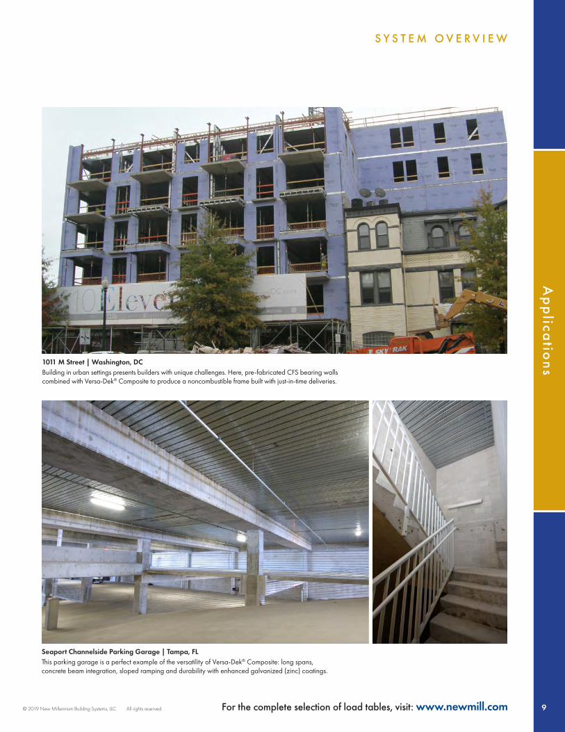
NOTES:1. Deck section properties are calculated in accordance with AISI S100-07. 2. Maximum clear spans without shoring and design web crippling strengths are based on deck bearing of 1.5" at end supports and 3" at interior supports.3. Maximum construction clear spans are based on ANSI/SDI C-2017 design criteria. For maximum clear spans based on different criteria contact New Millennium.4. Composite slab service stage calculations are based on ANSI/SDI C-2017 and ASCE 3-91. The slab weight has been subtracted from the service loads listed above.5. Uniform superimposed service loads were determined by dividing the superimposed LRFD design loads controlled by strength by the load factor of 1.6.6. The uniform service loads are based on the L/360 deflection limit under total load without considering long-term deflection. Visit newmill.com for load tables that consider long-term deflection.7. Temperature and shrinkage reinforcement in accordance with ANSI/SDI C-2017 shall be provided in the slab.8. Negative moment (top) reinforcement is required over supports of continuous spans. See tables entitled Maximum Design Negative Moment Capacity of Composite Slabs (page 24) for details.9. Continuous spans should be approximately equal with the span length difference not exceeding 20%.
MAXIMUM UNIFORM SUPERIMPOSED SERVICE LOADS
NOTES
24˝ Coverage
6˝
2˝
24˝ Coverage
6˝
2˝

23© 2019 New Millennium Building Systems, LLC All rights reserved. © 2019 New Millennium Building Systems, LLC All rights reserved. For the complete selection of load tables, visit: www.newmill.com
Co
mp
osite
Sp
an
Tab
les
Versa-Dek® 2.0 LS ES Composite 4000 PSI NORMAL-WEIGHT AND LIGHTWEIGHT CONCRETE
Versa-Dek Composite 2LS ESSUGGESTED REINFORCING STEEL OVER SUPPORTS FOR CONTINUOUS SLABS
Slab Depth(in.)
SlabSpan (ft)
LL=40 psf, SDL=20 psf LL=80 psf, SDL=5 psf LL=100 psf, SDL=5 psf-WL2/9 -WL2/10 -WL2/11 -WL2/9 -WL2/10 -WL2/11 -WL2/9 -WL2/10 -WL2/11
4 15 4@8 4@9 4@10 5@8 5@10 5@11 5@7 5@8 5@916 5@10 5@11 4@8 5@7 5@8 5@9 - 5@7 5@817 5@9 5@10 5@11 - 5@7 5@8 - - -18 5@8 5@9 5@10 - - 5@7 - - -19 - 5@7 5@8 - - - - - -
5 19 5@9 5@10 5@11 5@6 5@7 5@8 6@8 5@6 5@720 5@8 5@9 5@10 5@6 5@7 5@7 - 6@8 5@621 5@7 5@8 5@9 - 5@6 5@6 - - 6@822 5@6 5@7 5@8 - 6@7 5@6 - - -23 6@8 5@6 5@7 - - 6@7 - - -24 - 5@6 5@6 - - - - - -
5.25 18 5@10 4@8 4@8 5@8 5@9 5@10 5@7 5@8 5@820 5@8 5@9 5@10 5@6 5@7 5@8 6@7 5@6 5@722 5@7 5@7 5@8 6@7 6@8 5@6 - - 6@723 5@6 5@7 5@7 - 6@7 5@6 - - -24 6@7 5@6 5@7 - - 6@7 - - -25 - 6@8 5@6 - - - - - -26 - 6@7 5@6 - - - - - -
5.5 19 5@10 5@11 4@8 5@7 5@8 5@9 5@6 5@7 5@821 5@8 5@9 5@10 5@6 5@7 5@7 6@7 6@8 5@623 5@6 5@7 5@8 6@6 6@7 5@6 - - 6@724 5@6 5@6 5@7 - 6@7 6@8 - - 4@325 6@7 5@6 5@6 - - 6@7 - - -26 6@6 6@7 5@6 - - - - - -27 - 6@7 6@8 - - - - - -
6 20 5@9 5@11 4@8 5@7 5@8 5@9 5@6 5@7 5@822 5@8 5@9 5@10 5@6 5@6 5@7 6@7 6@8 5@624 5@6 5@7 5@8 6@7 6@7 5@6 - 6@6 6@725 5@6 5@6 5@7 6@6 6@7 6@8 - 6@6 6@626 6@7 5@6 5@6 - 6@6 6@7 - - 6@627 6@7 6@7 5@6 - 4@2 6@6 - - -28 6@6 6@7 6@8 - - 6@6 - - -
6.5 20 5@10 5@11 4@8 5@8 5@9 5@10 5@7 5@8 5@822 5@8 5@9 5@10 5@6 5@7 5@8 6@8 5@6 5@724 5@7 5@7 5@8 6@7 5@6 5@6 6@6 6@7 6@825 5@6 5@7 5@8 6@7 6@7 5@6 6@6 6@6 6@726 6@8 5@6 5@7 6@6 6@7 6@8 4@2 6@6 6@627 6@7 5@6 5@6 6@5 6@6 6@7 - 6@5 6@628 6@7 6@7 5@6 - 6@6 6@6 - - 6@5
7 22 5@9 5@10 5@11 5@7 5@8 5@8 5@6 5@7 5@723 5@8 5@9 5@10 5@6 5@7 5@8 6@7 5@6 5@724 5@7 5@8 5@9 6@8 5@6 5@7 6@7 6@8 5@625 5@6 5@7 5@8 6@7 5@6 5@6 6@6 6@7 6@826 5@6 5@7 5@7 6@6 6@7 5@6 6@6 6@6 6@727 6@8 5@6 5@7 6@6 6@7 6@8 6@5 6@6 6@628 6@7 5@6 5@6 6@5 6@6 6@7 - 6@5 6@6
7.5 22 5@9 5@10 5@11 5@7 5@8 5@9 5@6 5@7 5@823 5@8 5@9 5@10 5@6 5@7 5@8 5@6 5@6 5@724 5@7 5@8 5@9 5@6 5@7 5@7 6@7 5@6 5@625 5@7 5@8 5@9 6@8 5@6 5@7 6@7 6@7 5@626 5@6 5@7 5@8 6@7 6@8 5@6 6@6 6@7 6@827 5@6 5@6 5@7 6@6 6@7 5@6 6@5 6@6 6@728 6@8 5@6 5@7 6@6 6@7 6@7 6@5 6@6 6@6
8 22 5@10 5@11 4@8 5@8 5@9 5@10 5@7 5@7 5@823 5@9 5@10 5@11 5@7 5@8 5@9 5@6 5@7 5@824 5@8 5@9 5@10 5@6 5@7 5@8 6@8 5@6 5@725 5@7 5@8 5@9 5@6 5@6 5@7 6@7 5@6 5@626 5@7 5@7 5@8 6@7 5@6 5@7 6@6 6@7 5@627 5@6 5@7 5@8 6@7 6@8 5@6 6@6 6@7 6@728 5@6 5@6 5@7 6@6 6@7 6@8 6@5 6@6 6@7
NOTES:1. Reinforcing bars are required over interior supports for continuous spans. Reinforcing bars shall extend a minimum of 0.3L on each side of support.2. Table is based on reinforcing bars with Fy=60 ksi installed with 3/4" clear concrete cover over supports.3. Continuous spans should be approximately equal with the larger of the two adjacent spans not greater than the shorter by more than 20%.
See Custom Slab Designs discussion (page 19) for guidance on equal span design.4. The -WL2/9 columns apply to the interior support of the slab continuous over two spans; the -WL2/10 columns apply to the first interior support of the slab
continuous over more than two spans; the -WL2/11 columns apply to other interior supports of the slab continuous over more than two spans.
SUGGESTED REINFORCING STEEL OVER SUPPORTS FOR CONTINUOUS SLABS
NOTES
24˝ Coverage
6˝
2˝
24˝ Coverage
6˝
2˝

24 © 2019 New Millennium Building Systems, LLC All rights reserved.For the complete selection of load tables, visit: www.newmill.com
Co
mp
osi
te S
pa
n T
ab
les
Versa-Dek® 2.0 LS ES Composite 4000 PSI NORMAL-WEIGHT AND LIGHTWEIGHT CONCRETE
24˝ Coverage
6˝
2˝
24˝ Coverage
6˝
2˝
MAXIMUM DESIGN NEGATIVE MOMENT CAPACITY OF COMPOSITE SLABS
RebarfMn (ft-kips/ft)
Total Slab Thickness (in.)4 4.5 5 5.25 5.5 6
4000
PSI
of A
ny D
ensi
ty
4@12 2.537 2.987 3.437 3.662 3.887 4.3374@10 3.005 3.545 4.085 4.355 4.625 5.1654@8 3.683 4.358 5.033 5.371 5.708 6.3834@6 4.748 5.648 6.548 6.998 7.448 8.348
5@12 3.706 4.404 5.101 5.450 5.799 6.4965@10 4.354 5.191 6.028 6.446 6.865 7.7025@8 5.266 6.312 7.359 7.882 8.405 9.4515@6 - - 9.420 10.118 10.815 12.210
6@12 4.904 5.894 6.884 7.379 7.874 8.8646@10 - 6.884 8.072 8.666 9.260 10.4486@8 - - 9.735 10.477 11.220 12.7056@6 - - - - - -
RebarfMn (ft-kips/ft)
Total Slab Thickness (in.)6.25 6.5 7 7.5 8 8.25
4000
PSI
of A
ny D
ensi
ty
4@12 4.562 - - - - -4@10 5.435 5.705 6.245 - - -4@8 6.721 7.058 7.733 8.408 9.083 9.4214@6 8.798 9.248 10.148 11.048 11.948 12.398
5@12 6.845 7.194 7.891 8.589 9.286 9.6355@10 8.120 8.539 9.376 10.213 11.050 11.4685@8 9.974 10.497 11.544 12.590 13.636 14.1595@6 12.908 13.605 15.000 16.395 17.790 18.488
6@12 9.359 9.854 10.844 11.834 12.824 13.3196@10 11.042 11.636 12.824 14.012 15.200 15.7946@8 13.447 14.190 15.675 17.160 18.645 19.3876@6 17.141 18.131 20.111 22.091 24.071 25.061
NOTES:1 Table is based on Grade 60 ASTM A615 reinforcing bars with 3/4" concrete cover over supports.2 Slab self-weight has not been accounted for in the tabulated moment capacities. It should be included into the loads applied to the slab.
INSTRUCTIONS ON HOW TO SELECT A REINFORCEMENT PATTERN:Step 1 – Calculate required negative moment capacity, Mreq, as follows:Mreq,LRFD=[1.2(wslab+wD)+1.6wL]L2/C (LRFD)Where: wD = superimposed dead load, psf; wL = live load, psf; wslab = slab weight, psf; L = span length taken as the average of theadjacent span lengths (spans shall be approximately equal with the larger of two adjacent spans not greater than the shorter by morethan 20%), ft; Mreq,LRFD = required LRFD factored negative moment capacity, lb-ft/ft deck width; C = negative bending coefficient (9 forinterior support of two span continuous composite slab; 10 for first interior support of composite slab continuous over more than twospans; 11 for other interior supports of composite slab continuous over more than two spans).Step 2 – Select reinforcement size and spacing from table where fMn ≥ Mreq,LRFD (LRFD).
MAXIMUM DESIGN NEGATIVE MOMENT CAPACITY OF COMPOSITE SLABS
NOTES
MAXIMUM DESIGN NEGATIVE MOMENT CAPACITY OF COMPOSITE SLABS
RebarfMn (ft-kips/ft)
Total Slab Thickness (in.)4 4.5 5 5.25 5.5 6
4000
PSI
of A
ny D
ensi
ty
4@12 2.537 2.987 3.437 3.662 3.887 4.3374@10 3.005 3.545 4.085 4.355 4.625 5.1654@8 3.683 4.358 5.033 5.371 5.708 6.3834@6 4.748 5.648 6.548 6.998 7.448 8.348
5@12 3.706 4.404 5.101 5.450 5.799 6.4965@10 4.354 5.191 6.028 6.446 6.865 7.7025@8 5.266 6.312 7.359 7.882 8.405 9.4515@6 - - 9.420 10.118 10.815 12.210
6@12 4.904 5.894 6.884 7.379 7.874 8.8646@10 - 6.884 8.072 8.666 9.260 10.4486@8 - - 9.735 10.477 11.220 12.7056@6 - - - - - -
RebarfMn (ft-kips/ft)
Total Slab Thickness (in.)6.25 6.5 7 7.5 8 8.25
4000
PSI
of A
ny D
ensi
ty
4@12 4.562 - - - - -4@10 5.435 5.705 6.245 - - -4@8 6.721 7.058 7.733 8.408 9.083 9.4214@6 8.798 9.248 10.148 11.048 11.948 12.398
5@12 6.845 7.194 7.891 8.589 9.286 9.6355@10 8.120 8.539 9.376 10.213 11.050 11.4685@8 9.974 10.497 11.544 12.590 13.636 14.1595@6 12.908 13.605 15.000 16.395 17.790 18.488
6@12 9.359 9.854 10.844 11.834 12.824 13.3196@10 11.042 11.636 12.824 14.012 15.200 15.7946@8 13.447 14.190 15.675 17.160 18.645 19.3876@6 17.141 18.131 20.111 22.091 24.071 25.061
NOTES:1 Table is based on Grade 60 ASTM A615 reinforcing bars with 3/4" concrete cover over supports.2 Slab self-weight has not been accounted for in the tabulated moment capacities. It should be included into the loads applied to the slab.
INSTRUCTIONS ON HOW TO SELECT A REINFORCEMENT PATTERN:Step 1 – Calculate required negative moment capacity, Mreq, as follows:Mreq,LRFD=[1.2(wslab+wD)+1.6wL]L2/C (LRFD)Where: wD = superimposed dead load, psf; wL = live load, psf; wslab = slab weight, psf; L = span length taken as the average of theadjacent span lengths (spans shall be approximately equal with the larger of two adjacent spans not greater than the shorter by morethan 20%), ft; Mreq,LRFD = required LRFD factored negative moment capacity, lb-ft/ft deck width; C = negative bending coefficient (9 forinterior support of two span continuous composite slab; 10 for first interior support of composite slab continuous over more than twospans; 11 for other interior supports of composite slab continuous over more than two spans).Step 2 – Select reinforcement size and spacing from table where fMn ≥ Mreq,LRFD (LRFD).
MAXIMUM DESIGN NEGATIVE MOMENT CAPACITY OF COMPOSITE SLABS
RebarfMn (ft-kips/ft)
Total Slab Thickness (in.)4 4.5 5 5.25 5.5 6
4000
PSI
of A
ny D
ensi
ty
4@12 2.537 2.987 3.437 3.662 3.887 4.3374@10 3.005 3.545 4.085 4.355 4.625 5.1654@8 3.683 4.358 5.033 5.371 5.708 6.3834@6 4.748 5.648 6.548 6.998 7.448 8.348
5@12 3.706 4.404 5.101 5.450 5.799 6.4965@10 4.354 5.191 6.028 6.446 6.865 7.7025@8 5.266 6.312 7.359 7.882 8.405 9.4515@6 - - 9.420 10.118 10.815 12.210
6@12 4.904 5.894 6.884 7.379 7.874 8.8646@10 - 6.884 8.072 8.666 9.260 10.4486@8 - - 9.735 10.477 11.220 12.7056@6 - - - - - -
RebarfMn (ft-kips/ft)
Total Slab Thickness (in.)6.25 6.5 7 7.5 8 8.25
4000
PSI
of A
ny D
ensi
ty
4@12 4.562 - - - - -4@10 5.435 5.705 6.245 - - -4@8 6.721 7.058 7.733 8.408 9.083 9.4214@6 8.798 9.248 10.148 11.048 11.948 12.398
5@12 6.845 7.194 7.891 8.589 9.286 9.6355@10 8.120 8.539 9.376 10.213 11.050 11.4685@8 9.974 10.497 11.544 12.590 13.636 14.1595@6 12.908 13.605 15.000 16.395 17.790 18.488
6@12 9.359 9.854 10.844 11.834 12.824 13.3196@10 11.042 11.636 12.824 14.012 15.200 15.7946@8 13.447 14.190 15.675 17.160 18.645 19.3876@6 17.141 18.131 20.111 22.091 24.071 25.061
NOTES:1 Table is based on Grade 60 ASTM A615 reinforcing bars with 3/4" concrete cover over supports.2 Slab self-weight has not been accounted for in the tabulated moment capacities. It should be included into the loads applied to the slab.
INSTRUCTIONS ON HOW TO SELECT A REINFORCEMENT PATTERN:Step 1 – Calculate required negative moment capacity, Mreq, as follows:Mreq,LRFD=[1.2(wslab+wD)+1.6wL]L2/C (LRFD)Where: wD = superimposed dead load, psf; wL = live load, psf; wslab = slab weight, psf; L = span length taken as the average of theadjacent span lengths (spans shall be approximately equal with the larger of two adjacent spans not greater than the shorter by morethan 20%), ft; Mreq,LRFD = required LRFD factored negative moment capacity, lb-ft/ft deck width; C = negative bending coefficient (9 forinterior support of two span continuous composite slab; 10 for first interior support of composite slab continuous over more than twospans; 11 for other interior supports of composite slab continuous over more than two spans).Step 2 – Select reinforcement size and spacing from table where fMn ≥ Mreq,LRFD (LRFD).
INSTRUCTIONS ON HOW TO SELECT A REINFORCEMENT PATTERN:

25© 2019 New Millennium Building Systems, LLC All rights reserved. © 2019 New Millennium Building Systems, LLC All rights reserved. For the complete selection of load tables, visit: www.newmill.com
Co
mp
osite
Sp
an
Tab
les
Versa-Dek® 3.5 LS Composite 4000 PSI NORMAL-WEIGHT CONCRETE
Versa-Dek Composite 3.5LSDECK PROPERTIES
Gage Thickness(in.)
Coverage(in.)
Weight(psf) Fy (ksi) As
(in.2/ft)ID (in.4/ft) Sp
(in.3/ft)Sn
(in.3/ft)fVn
(lb/ft)fRbe
(lb/ft)fRbi
(lb/ft)single multi20 0.0358 24 3.33 40 0.978 1.959 1.959 0.775 0.910 5501 952 195419 0.0418 24 3.88 40 1.141 2.324 2.324 0.946 1.090 7500 1275 259418 0.0474 24 4.40 40 1.293 2.664 2.664 1.113 1.226 9644 1615 326416 0.0598 24 5.54 40 1.629 3.394 3.394 1.504 1.573 13477 2496 4990
Fy is steel yield stress; As is area of deck; ID is deck moment of inertia for deflection calculations; Sp and Sn are deck section moduli in positive and negative bending, respectively; fVn isdesign shear strength of deck; fRbe and fRbi are design web crippling strengths of deck for end and interior bearing, respectively.
MAXIMUM ALLOWABLE SPANS - NORMAL WEIGHT CONCRETE (145 PCF), f'c=4000 PSI - LRFD
Total SlabDepth(in.)
Service Stage Construction StageSimple Spans (ft-in.) Continuous Spans (ft-in.) Maximum Unshored Clear
Spans (ft-in.)LL=40 psfSDL=20 psf
LL=80 psfSDL=5 psf
LL=100 psfSDL=5 psf
LL=40 psf; SDL=20 psf LL=80 psf; SDL=5 psf LL=100 psf; SDL=5 psfinterior span end span interior span end span interior span end span single double triple
20 GA Deck5.5 17' - 5" 14' - 11" 13' - 8" 20' - 10" 17' - 5" 17' - 10" 14' - 11" 16' - 5" 13' - 8" 12' - 0" 12' - 10" 13' - 5"
5.75 17' - 9" 15' - 3" 14' - 0" 21' - 4" 17' - 9" 18' - 3" 15' - 3" 16' - 10" 14' - 0" 11' - 9" 12' - 5" 12' - 11"6 18' - 1" 15' - 7" 14' - 4" 21' - 9" 18' - 1" 18' - 8" 15' - 7" 17' - 2" 14' - 4" 11' - 7" 11' - 11" 12' - 5"
6.25 18' - 6" 15' - 11" 14' - 8" 22' - 2" 18' - 6" 19' - 1" 15' - 11" 17' - 7" 14' - 8" 11' - 4" 11' - 6" 12' - 0"6.5 18' - 10" 16' - 2" 14' - 11" 22' - 7" 18' - 10" 19' - 5" 16' - 2" 17' - 11" 14' - 11" 11' - 1" 11' - 1" 11' - 7"7 19' - 5" 16' - 9" 15' - 6" 23' - 4" 19' - 5" 20' - 2" 16' - 9" 18' - 7" 15' - 6" 10' - 9" 10' - 5" 10' - 10"
7.25 19' - 8" 17' - 1" 15' - 9" 23' - 8" 19' - 8" 20' - 6" 17' - 1" 18' - 11" 15' - 9" 10' - 7" 10' - 1" 10' - 6"7.5 19' - 8" 17' - 4" 16' - 0" 23' - 8" 19' - 8" 20' - 9" 17' - 4" 19' - 2" 16' - 0" 10' - 5" 9' - 9" 10' - 2"8 20' - 2" 17' - 10" 16' - 6" 24' - 3" 20' - 2" 21' - 5" 17' - 10" 19' - 9" 16' - 6" 10' - 1" 9' - 3" 9' - 7"
19 GA Deck5.5 18' - 3" 17' - 2" 16' - 4" 25' - 4" 21' - 1" 21' - 5" 17' - 10" 19' - 7" 16' - 4" 13' - 6" 14' - 8" 15' - 2"
5.75 18' - 11" 17' - 9" 16' - 9" 25' - 11" 21' - 7" 21' - 11" 18' - 3" 20' - 1" 16' - 9" 13' - 2" 14' - 4" 14' - 10"6 19' - 6" 18' - 4" 17' - 1" 26' - 6" 22' - 1" 22' - 5" 18' - 8" 20' - 7" 17' - 1" 12' - 11" 14' - 1" 14' - 7"
6.25 20' - 1" 18' - 11" 17' - 6" 27' - 0" 22' - 6" 22' - 11" 19' - 1" 21' - 0" 17' - 6" 12' - 8" 13' - 10" 14' - 4"6.5 20' - 8" 19' - 6" 17' - 11" 27' - 7" 23' - 0" 23' - 5" 19' - 6" 21' - 6" 17' - 11" 12' - 5" 13' - 7" 14' - 1"7 21' - 9" 20' - 3" 18' - 7" 28' - 7" 23' - 9" 24' - 4" 20' - 3" 22' - 4" 18' - 7" 12' - 0" 13' - 2" 13' - 7"
7.25 22' - 4" 20' - 8" 18' - 11" 29' - 0" 24' - 2" 24' - 9" 20' - 8" 22' - 9" 18' - 11" 11' - 9" 13' - 0" 13' - 5"7.5 22' - 10" 21' - 0" 19' - 3" 29' - 6" 24' - 7" 25' - 2" 21' - 0" 23' - 2" 19' - 3" 11' - 7" 12' - 9" 13' - 2"8 24' - 0" 21' - 8" 19' - 11" 29' - 10" 24' - 10" 26' - 0" 21' - 8" 23' - 11" 19' - 11" 11' - 3" 12' - 2" 12' - 8"
18 GA Deck5.5 18' - 7" 17' - 5" 16' - 8" 27' - 6" 22' - 11" 24' - 8" 20' - 7" 22' - 6" 18' - 9" 14' - 5" 15' - 6" 16' - 0"
5.75 19' - 2" 18' - 0" 17' - 3" 28' - 5" 23' - 8" 25' - 5" 21' - 2" 23' - 1" 19' - 3" 14' - 3" 15' - 2" 15' - 8"6 19' - 9" 18' - 7" 17' - 10" 29' - 3" 24' - 5" 26' - 0" 21' - 8" 23' - 9" 19' - 9" 14' - 1" 14' - 11" 15' - 5"
6.25 20' - 4" 19' - 2" 18' - 5" 30' - 2" 25' - 1" 26' - 8" 22' - 2" 24' - 3" 20' - 3" 13' - 10" 14' - 8" 15' - 2"6.5 20' - 11" 19' - 9" 19' - 0" 31' - 0" 25' - 10" 27' - 3" 22' - 8" 24' - 10" 20' - 8" 13' - 7" 14' - 5" 14' - 11"7 22' - 1" 20' - 10" 20' - 1" 32' - 8" 27' - 3" 28' - 4" 23' - 7" 25' - 11" 21' - 7" 13' - 1" 13' - 11" 14' - 5"
7.25 22' - 7" 21' - 5" 20' - 8" 33' - 6" 27' - 11" 28' - 10" 24' - 1" 26' - 5" 22' - 0" 12' - 11" 13' - 9" 14' - 2"7.5 23' - 2" 22' - 0" 21' - 2" 34' - 2" 28' - 5" 29' - 5" 24' - 6" 26' - 10" 22' - 5" 12' - 8" 13' - 6" 14' - 0"8 24' - 3" 23' - 1" 22' - 3" 35' - 2" 29' - 4" 30' - 5" 25' - 4" 27' - 10" 23' - 2" 12' - 3" 13' - 1" 13' - 7"
16 GA Deck5.5 19' - 1" 17' - 11" 17' - 2" 27' - 10" 23' - 7" 24' - 7" 22' - 2" 22' - 11" 21' - 3" 15' - 3" 17' - 5" 17' - 11"
5.75 19' - 8" 18' - 6" 17' - 9" 29' - 1" 24' - 4" 25' - 9" 22' - 10" 24' - 0" 21' - 11" 15' - 1" 17' - 1" 17' - 8"6 20' - 3" 19' - 1" 18' - 4" 30' - 1" 25' - 1" 26' - 10" 23' - 7" 25' - 1" 22' - 8" 14' - 11" 16' - 10" 17' - 4"
6.25 20' - 10" 19' - 8" 18' - 11" 30' - 11" 25' - 9" 27' - 11" 24' - 4" 26' - 1" 23' - 4" 14' - 9" 16' - 6" 17' - 1"6.5 21' - 5" 20' - 3" 19' - 6" 31' - 10" 26' - 6" 29' - 0" 25' - 0" 27' - 2" 24' - 1" 14' - 7" 16' - 3" 16' - 9"7 22' - 7" 21' - 5" 20' - 7" 33' - 7" 27' - 11" 31' - 2" 26' - 6" 29' - 2" 25' - 6" 14' - 4" 15' - 9" 16' - 3"
7.25 23' - 2" 22' - 0" 21' - 2" 34' - 5" 28' - 8" 32' - 3" 27' - 2" 30' - 3" 26' - 2" 14' - 2" 15' - 6" 16' - 0"7.5 23' - 9" 22' - 7" 21' - 9" 35' - 3" 29' - 4" 33' - 3" 27' - 10" 31' - 3" 26' - 10" 14' - 1" 15' - 3" 15' - 9"8 24' - 11" 23' - 8" 22' - 10" 36' - 11" 30' - 9" 35' - 1" 29' - 3" 33' - 2" 28' - 2" 13' - 10" 14' - 10" 15' - 4"
NOTES:1. Deck section properties are calculated in accordance with AISI S100-07. 2. Maximum clear spans without shoring and design web crippling strengths are based on deck bearing of 1.5" at end supports and 3" at interior supports.3. Maximum construction clear spans are based on ANSI/SDI C-2017 design criteria. For maximum clear spans based on different criteria contact New Millennium. 4. Composite slab service stage calculations are based on ANSI/SDI C-2017 and ASCE 3-91. 5. The service stage spans are based on the instantaneous deflection limit of L/360 under total load. Contact New Millennium for maximum span based on alternative deflection.6. Long-term deflection has not been taken into consideration. Visit newmill.com for load tables that consider long-term deflection.7. Temperature and shrinkage reinforcement in accordance with ANSI/SDI C-2017 shall be provided in the slab.8. Negative moment (top) reinforcement is required over supports of continuous spans. See table entitled Suggested Reinforcing Steel Over Supports for Continuous Slabs (page 28) for details.9. Continuous spans should be approximately equal with the span length difference not exceeding 20%. See Custom Slab Designs discussion (page 19) for guidance on unequal span design.
MAXIMUM ALLOWABLE SPANS (SERVICE AND CONSTRUCTION STAGE) – NORMAL-WEIGHT CONCRETE (145 PCF), f'c = 4000 PSI
NOTES
DECK DESCRIPTION SECTION PROPERTIES STRENGTHS (BARE DECK)
24˝ Coverage
8˝
213 ˝
24˝ Coverage
8˝
213 ˝

26 © 2019 New Millennium Building Systems, LLC All rights reserved.For the complete selection of load tables, visit: www.newmill.com
Co
mp
osi
te S
pa
n T
ab
les
Versa-Dek® 3.5 LS Composite4000 PSI LIGHTWEIGHT CONCRETE
Versa-Dek Composite 3.5LSDECK PROPERTIES
Gage Thickness(in.)
Coverage(in.)
Weight(psf) Fy (ksi) As
(in.2/ft)ID (in.4/ft) Sp
(in.3/ft)Sn
(in.3/ft)fVn
(lb/ft)fRbe
(lb/ft)fRbi
(lb/ft)single multi20 0.0358 24 3.33 40 0.978 1.959 1.959 0.775 0.910 5501 952 195419 0.0418 24 3.88 40 1.141 2.324 2.324 0.946 1.090 7500 1275 259418 0.0474 24 4.40 40 1.293 2.664 2.664 1.113 1.226 9644 1615 326416 0.0598 24 5.54 40 1.629 3.394 3.394 1.504 1.573 13477 2496 4990
Fy is steel yield stress; As is area of deck; ID is deck moment of inertia for deflection calculations; Sp and Sn are deck section moduli in positive and negative bending, respectively; fVn isdesign shear strength of deck; fRbe and fRbi are design web crippling strengths of deck for end and interior bearing, respectively.
MAXIMUM ALLOWABLE SPANS - LIGHTWEIGHT CONCRETE (110 PCF), f'c=4000 PSI - LRFD
Total SlabDepth(in.)
Service Stage Construction StageSimple Spans (ft-in.) Continuous Spans (ft-in.) Maximum Unshored Clear
Spans (ft-in.)LL=40 psfSDL=20 psf
LL=80 psfSDL=5 psf
LL=100 psfSDL=5 psf
LL=40 psf; SDL=20 psf LL=80 psf; SDL=5 psf LL=100 psf; SDL=5 psfinterior span end span interior span end span interior span end span single double triple
20 GA Deck5.5 17' - 2" 15' - 0" 13' - 10" 21' - 2" 17' - 8" 18' - 1" 15' - 0" 16' - 7" 13' - 10" 13' - 5" 14' - 9" 15' - 3"
5.75 17' - 9" 15' - 5" 14' - 2" 21' - 8" 18' - 1" 18' - 6" 15' - 5" 17' - 0" 14' - 2" 13' - 2" 14' - 6" 15' - 0"6 18' - 4" 15' - 9" 14' - 6" 22' - 1" 18' - 5" 18' - 11" 15' - 9" 17' - 4" 14' - 6" 12' - 11" 14' - 3" 14' - 9"
6.25 18' - 10" 16' - 1" 14' - 9" 22' - 7" 18' - 10" 19' - 4" 16' - 1" 17' - 9" 14' - 9" 12' - 8" 14' - 0" 14' - 6"6.5 19' - 2" 16' - 5" 15' - 1" 23' - 0" 19' - 2" 19' - 8" 16' - 5" 18' - 1" 15' - 1" 12' - 5" 13' - 8" 14' - 3"7 19' - 9" 17' - 0" 15' - 8" 23' - 9" 19' - 9" 20' - 5" 17' - 0" 18' - 10" 15' - 8" 12' - 0" 12' - 10" 13' - 4"
7.25 20' - 1" 17' - 4" 15' - 11" 24' - 1" 20' - 1" 20' - 9" 17' - 4" 19' - 2" 15' - 11" 11' - 10" 12' - 5" 13' - 0"7.5 20' - 5" 17' - 7" 16' - 2" 24' - 6" 20' - 5" 21' - 1" 17' - 7" 19' - 5" 16' - 2" 11' - 8" 12' - 1" 12' - 7"8 20' - 11" 18' - 1" 16' - 9" 25' - 2" 20' - 11" 21' - 9" 18' - 1" 20' - 1" 16' - 9" 11' - 4" 11' - 5" 11' - 11"
19 GA Deck5.5 17' - 6" 16' - 4" 15' - 7" 25' - 9" 21' - 5" 21' - 8" 18' - 0" 19' - 9" 16' - 5" 14' - 11" 16' - 2" 16' - 8"
5.75 18' - 1" 16' - 10" 16' - 1" 26' - 4" 22' - 0" 22' - 2" 18' - 6" 20' - 3" 16' - 11" 14' - 9" 15' - 10" 16' - 5"6 18' - 8" 17' - 5" 16' - 8" 27' - 0" 22' - 6" 22' - 9" 18' - 11" 20' - 9" 17' - 4" 14' - 5" 15' - 7" 16' - 1"
6.25 19' - 2" 18' - 0" 17' - 2" 27' - 7" 22' - 11" 23' - 3" 19' - 5" 21' - 3" 17' - 9" 14' - 2" 15' - 4" 15' - 10"6.5 19' - 9" 18' - 6" 17' - 9" 28' - 1" 23' - 5" 23' - 9" 19' - 10" 21' - 9" 18' - 1" 13' - 11" 15' - 1" 15' - 7"7 20' - 10" 19' - 7" 18' - 9" 29' - 2" 24' - 4" 24' - 9" 20' - 7" 22' - 7" 18' - 10" 13' - 5" 14' - 7" 15' - 1"
7.25 21' - 5" 20' - 2" 19' - 2" 29' - 8" 24' - 9" 25' - 2" 21' - 0" 23' - 0" 19' - 2" 13' - 3" 14' - 5" 14' - 11"7.5 22' - 0" 20' - 8" 19' - 7" 30' - 2" 25' - 1" 25' - 7" 21' - 4" 23' - 5" 19' - 7" 13' - 0" 14' - 2" 14' - 8"8 23' - 0" 21' - 9" 20' - 2" 31' - 1" 25' - 11" 26' - 5" 22' - 0" 24' - 3" 20' - 2" 12' - 7" 13' - 10" 14' - 3"
18 GA Deck5.5 17' - 10" 16' - 7" 15' - 10" 26' - 5" 22' - 0" 24' - 7" 20' - 6" 22' - 9" 18' - 11" 15' - 5" 17' - 1" 17' - 8"
5.75 18' - 4" 17' - 2" 16' - 4" 27' - 3" 22' - 8" 25' - 5" 21' - 2" 23' - 4" 19' - 6" 15' - 3" 16' - 9" 17' - 4"6 18' - 11" 17' - 8" 16' - 11" 28' - 1" 23' - 5" 26' - 3" 21' - 10" 24' - 0" 20' - 0" 15' - 0" 16' - 6" 17' - 0"
6.25 19' - 6" 18' - 3" 17' - 5" 28' - 11" 24' - 1" 27' - 0" 22' - 6" 24' - 7" 20' - 6" 14' - 10" 16' - 2" 16' - 9"6.5 20' - 1" 18' - 10" 18' - 0" 29' - 9" 24' - 10" 27' - 7" 23' - 0" 25' - 2" 20' - 11" 14' - 9" 15' - 11" 16' - 6"7 21' - 2" 19' - 11" 19' - 1" 31' - 5" 26' - 2" 28' - 10" 24' - 0" 26' - 3" 21' - 10" 14' - 5" 15' - 6" 16' - 0"
7.25 21' - 9" 20' - 5" 19' - 7" 32' - 3" 26' - 10" 29' - 4" 24' - 6" 26' - 9" 22' - 3" 14' - 3" 15' - 3" 15' - 9"7.5 22' - 3" 21' - 0" 20' - 1" 33' - 1" 27' - 6" 29' - 11" 24' - 11" 27' - 3" 22' - 8" 14' - 2" 15' - 0" 15' - 6"8 23' - 4" 22' - 0" 21' - 2" 34' - 8" 28' - 10" 30' - 11" 25' - 9" 28' - 3" 23' - 6" 13' - 10" 14' - 7" 15' - 1"
16 GA Deck5.5 18' - 5" 17' - 2" 16' - 5" 27' - 4" 22' - 9" 25' - 6" 21' - 3" 23' - 8" 20' - 3" 16' - 3" 19' - 2" 19' - 0"
5.75 18' - 11" 17' - 8" 16' - 11" 28' - 1" 23' - 5" 26' - 3" 21' - 10" 24' - 10" 20' - 11" 16' - 1" 18' - 10" 18' - 10"6 19' - 6" 18' - 3" 17' - 5" 28' - 11" 24' - 1" 27' - 0" 22' - 6" 25' - 10" 21' - 6" 15' - 11" 18' - 6" 18' - 7"
6.25 20' - 1" 18' - 9" 18' - 0" 29' - 9" 24' - 9" 27' - 10" 23' - 3" 26' - 8" 22' - 2" 15' - 9" 18' - 3" 18' - 5"6.5 20' - 8" 19' - 4" 18' - 6" 30' - 7" 25' - 6" 28' - 8" 23' - 11" 27' - 5" 22' - 11" 15' - 7" 17' - 11" 18' - 3"7 21' - 9" 20' - 6" 19' - 7" 32' - 4" 26' - 11" 30' - 4" 25' - 3" 29' - 1" 24' - 3" 15' - 3" 17' - 5" 17' - 11"
7.25 22' - 4" 21' - 0" 20' - 2" 33' - 2" 27' - 7" 31' - 2" 26' - 0" 29' - 11" 24' - 11" 15' - 1" 17' - 2" 17' - 9"7.5 22' - 11" 21' - 7" 20' - 8" 34' - 0" 28' - 4" 32' - 0" 26' - 8" 30' - 8" 25' - 7" 15' - 0" 16' - 11" 17' - 6"8 24' - 0" 22' - 8" 21' - 9" 35' - 7" 29' - 8" 33' - 7" 28' - 0" 32' - 3" 26' - 11" 14' - 9" 16' - 6" 17' - 0"
NOTES:1. Deck section properties are calculated in accordance with AISI S100-07. 2. Maximum clear spans without shoring and design web crippling strengths are based on deck bearing of 1.5" at end supports and 3" at interior supports.3. Maximum construction clear spans are based on ANSI/SDI C-2017 design criteria. For maximum clear spans based on different criteria contact New Millennium. 4. Composite slab service stage calculations are based on ANSI/SDI C-2017 and ASCE 3-91. 5. The service stage spans are based on the instantaneous deflection limit of L/360 under total load. Contact New Millennium for maximum spans based on alternative deflection criteria.6. Long-term deflection has not been taken into consideration. Visit newmill.com for load tables that consider long-term deflection.7. Temperature and shrinkage reinforcement in accordance with ANSI/SDI C-2017 shall be provided in the slab.8. Negative moment (top) reinforcement is required over supports of continuous spans. See table entitled Suggested Reinforcing Steel Over Supports for Continuous Slabs (page 28) for details.9. Continuous spans should be approximately equal with the span length difference not exceeding 20%. See Custom Slab Designs discussion (page 19) for guidance on unequal span design.
MAXIMUM ALLOWABLE SPANS (SERVICE AND CONSTRUCTION STAGE) – LIGHTWEIGHT CONCRETE (110 PCF), f'c = 4000 PSI
NOTES
DECK DESCRIPTION SECTION PROPERTIES STRENGTHS (BARE DECK)
24˝ Coverage
8˝
213 ˝
24˝ Coverage
8˝
213 ˝
27© 2019 New Millennium Building Systems, LLC All rights reserved. © 2019 New Millennium Building Systems, LLC All rights reserved. For the complete selection of load tables, visit: www.newmill.com
Co
mp
osite
Sp
an
Tab
les
Versa-Dek® 3.5 LS Composite4000 PSI NORMAL-WEIGHT AND LIGHTWEIGHT CONCRETE
24˝ Coverage
8˝
213 ˝
24˝ Coverage
8˝
213 ˝
Versa-Dek Composite 3.5LS
Conc
rete Slab Depth,
Concrete Weight,Concrete Volume,
WWF Deck
Gag
e Maximum Unshored ClearSpans (ft-in.) Uniform Service Load Capacity, PSF / Spans (ft.)
single double triple Simple Span Conditions Continuous Span ConditionNegative Moment Reinforcement Required
10 12 14 16 17 18 19 20 16 18 20 22 24 26 28
4,00
0 PS
I Nor
mal
Wei
ght C
oncr
ete
(145
PSF
)
5.75" 20 11' - 9" 12' - 5" 12' - 11" 243 152 104 73 62 53 45 36 73 53 39 28 20 12 459 PSF 19 13' - 2" 14' - 4" 14' - 10" 339 232 156 115 100 79 58 41 115 87 67 52 41 23 5
1.5 cu.yd/(100sq.ft) 18 14' - 3" 15' - 2" 15' - 8" 436 301 220 148 113 85 63 45 157 121 95 76 52 27 86x6 - W1.4 x W1.4 16 15' - 1" 17' - 1" 17' - 8" 500 380 267 167 128 98 74 54 248 194 148 100 62 34 14
6" 20 11' - 7" 11' - 11" 12' - 5" 257 161 110 78 66 56 48 41 78 56 41 30 20 13 862 PSF 19 12' - 11" 14' - 1" 14' - 7" 358 245 165 122 106 92 70 50 122 92 71 55 44 31 111.58
cu.yd/(100sq.ft)18 14' - 1" 14' - 11" 15' - 5" 461 319 233 166 132 100 75 55 166 128 101 81 63 35 14
6x6 - W1.4 x W1.4 16 14' - 11" 16' - 10" 17' - 4" 500 412 289 192 149 115 87 65 262 207 167 117 74 43 216.5" 20 11' - 1" 11' - 1" 11' - 7" 285 178 122 86 73 62 53 46 86 62 46 33 22 15 10
68 PSF 19 12' - 5" 13' - 7" 14' - 1" 398 272 184 135 117 102 90 73 135 102 79 62 49 39 271.74
cu.yd/(100sq.ft)18 13' - 7" 14' - 5" 14' - 11" 500 353 246 184 161 135 104 79 184 142 112 90 73 54 28
6x6 - W1.4 x W1.4 16 14' - 7" 16' - 3" 16' - 9" 500 500 393 249 195 153 119 92 291 229 185 152 103 65 367" 20 10' - 9" 10' - 5" 10' - 10" 313 196 134 95 81 69 59 50 95 69 50 34 24 17 11
74 PSF 19 12' - 0" 13' - 2" 13' - 7" 437 285 202 149 129 112 99 87 149 112 87 68 54 43 321.89
cu.yd/(100sq.ft)18 13' - 1" 13' - 11" 14' - 5" 500 388 270 203 177 156 138 107 203 156 123 99 81 66 49
6x6 - W2.0 x W2.0 16 14' - 4" 15' - 9" 16' - 3" 500 500 431 315 250 198 156 123 320 252 204 168 137 90 567.25" 20 10' - 7" 10' - 1" 10' - 6" 327 205 141 100 84 72 61 53 100 72 53 36 25 17 11
77 PSF 19 11' - 9" 13' - 0" 13' - 5" 456 298 211 155 135 118 103 91 155 118 91 71 56 42 331.97
cu.yd/(100sq.ft)18 12' - 11" 13' - 9" 14' - 2" 500 406 282 212 185 163 145 123 212 163 129 104 84 69 55
6x6 - W2.0 x W2.0 16 14' - 2" 15' - 6" 16' - 0" 500 500 451 334 280 223 177 140 334 264 213 175 147 105 667.5" 20 10' - 5" 9' - 9" 10' - 2" 341 214 147 104 88 75 64 52 104 75 52 38 27 18 12
80 PSF 19 11' - 7" 12' - 9" 13' - 2" 476 310 220 162 141 123 108 95 162 123 95 74 59 44 352.04
cu.yd/(100sq.ft)18 12' - 8" 13' - 6" 14' - 0" 500 423 294 221 193 171 151 135 221 171 135 108 88 72 57
6x6 - W2.0 x W2.0 16 14' - 1" 15' - 3" 15' - 9" 500 500 470 348 308 250 200 159 348 275 222 183 153 120 788" 20 10' - 1" 9' - 3" 9' - 7" 370 231 159 113 96 81 67 57 113 81 57 41 29 20 13
86 PSF 19 11' - 3" 12' - 2" 12' - 8" 500 336 239 176 152 133 117 103 176 133 103 80 64 48 382.2 cu.yd/(100sq.ft) 18 12' - 3" 13' - 1" 13' - 7" 500 458 319 239 210 185 164 146 239 185 146 117 95 78 624x4 - W1.4 x W1.4 16 13' - 10" 14' - 10" 15' - 4" 500 500 493 377 334 298 250 201 377 298 241 198 166 140 105
4,00
0 PS
I Lig
htw
eigh
t Con
cret
e (1
10 P
SF)
5.75" 20 13' - 2" 14' - 6" 15' - 0" 243 163 106 76 65 55 40 27 76 55 41 31 23 14 145 PSF 19 14' - 9" 15' - 10" 16' - 5" 339 232 167 108 82 61 45 32 118 89 69 55 37 18 4
1.5 cu.yd/(100sq.ft) 18 15' - 3" 16' - 9" 17' - 4" 436 301 220 116 88 67 49 35 159 123 98 68 41 21 76x6 - W1.4 x W1.4 16 16' - 1" 18' - 10" 18' - 10" 500 391 273 183 102 78 59 43 259 190 124 80 50 28 12
6" 20 12' - 11" 14' - 3" 14' - 9" 257 172 113 80 69 59 48 34 80 59 43 32 24 18 547 PSF 19 14' - 5" 15' - 7" 16' - 1" 358 245 177 124 95 72 54 39 124 95 74 58 45 24 81.58
cu.yd/(100sq.ft)18 15' - 0" 16' - 6" 17' - 0" 461 319 233 133 102 78 59 43 169 131 104 80 49 27 11
6x6 - W1.4 x W1.4 16 15' - 11" 18' - 6" 18' - 7" 500 423 300 151 117 90 69 52 265 209 141 92 59 34 176.5" 20 12' - 5" 13' - 8" 14' - 3" 285 191 125 89 76 65 56 48 89 65 48 36 27 20 13
52 PSF 19 13' - 11" 15' - 1" 15' - 7" 398 272 187 138 120 98 75 56 138 105 82 65 52 38 191.74
cu.yd/(100sq.ft)18 14' - 9" 15' - 11" 16' - 6" 500 353 258 173 135 105 81 61 187 145 115 93 69 42 22
6x6 - W1.4 x W1.4 16 15' - 7" 17' - 11" 18' - 3" 500 500 376 194 153 120 93 72 294 232 183 123 81 51 297" 20 12' - 0" 12' - 10" 13' - 4" 313 210 138 98 84 72 62 53 98 72 53 40 30 20 14
56 PSF 19 13' - 5" 14' - 7" 15' - 1" 437 298 205 152 132 116 99 77 152 116 90 71 57 46 311.89
cu.yd/(100sq.ft)18 14' - 5" 15' - 6" 16' - 0" 500 388 284 206 173 136 107 83 206 159 126 102 84 60 35
6x6 - W2.0 x W2.0 16 15' - 3" 17' - 5" 17' - 11" 500 500 431 246 194 154 122 96 323 255 207 158 107 70 437.25" 20 11' - 10" 12' - 5" 13' - 0" 327 208 144 103 88 75 65 56 103 75 56 42 31 21 15
58 PSF 19 13' - 3" 14' - 5" 14' - 11" 456 312 214 159 138 121 106 88 159 121 94 74 59 48 381.97
cu.yd/(100sq.ft)18 14' - 3" 15' - 3" 15' - 9" 500 406 297 215 189 154 121 95 215 167 132 107 88 70 43
6x6 - W2.0 x W2.0 16 15' - 1" 17' - 2" 17' - 9" 500 500 451 274 218 173 138 109 337 267 216 178 122 81 527.5" 20 11' - 8" 12' - 1" 12' - 7" 341 217 150 107 92 78 67 58 107 78 58 44 33 22 16
61 PSF 19 13' - 0" 14' - 2" 14' - 8" 476 325 224 166 144 126 111 98 166 126 98 78 62 50 412.04
cu.yd/(100sq.ft)18 14' - 2" 15' - 0" 15' - 6" 500 423 309 224 197 173 137 108 224 174 138 111 91 76 51
6x6 - W2.0 x W2.0 16 15' - 0" 16' - 11" 17' - 6" 500 500 470 305 243 194 155 124 352 278 226 186 138 93 618" 20 11' - 4" 11' - 5" 11' - 11" 370 235 162 116 99 85 73 63 116 85 63 47 33 24 17
65 PSF 19 12' - 7" 13' - 10" 14' - 3" 500 352 242 179 156 137 120 106 179 137 106 84 67 54 422.2 cu.yd/(100sq.ft) 18 13' - 10" 14' - 7" 15' - 1" 500 458 322 243 213 188 167 137 243 188 149 121 99 82 694x4 - W1.4 x W1.4 16 14' - 9" 16' - 6" 17' - 0" 500 500 500 372 298 240 194 156 381 301 244 202 169 120 81
NOTES:1. Deck section properties are calculated in accordance with AISI S100-07. 2. Maximum clear spans without shoring and design web crippling strengths are based on deck bearing of 1.5" at end supports and 3" at interior supports.3. Maximum construction clear spans are based on ANSI/SDI C-2017 design criteria. For maximum clear spans based on different criteria contact New Millennium. 4. Composite slab service stage calculations are based on ANSI/SDI C-2017 and ASCE 3-91. The slab weight has been subtracted from the service loads listed above.5. Uniform superimposed service loads were determined by dividing the superimposed LRFD design loads controlled by strength by the load factor of 1.6.6. The uniform service loads are based on the L/360 deflection limit under total load without considering long-term deflection. Visit newmill.com for load tables that consider long-term deflection.7. Temperature and shrinkage reinforcement in accordance with ANSI/SDI C-2017 shall be provided in the slab.8. Negative moment (top) reinforcement is required over supports of continuous spans. See table entitled Maximum Design Negative Moment Capacity of Composite Slabs (page 29) for details.9. Continuous spans should be approximately equal with the span length difference not exceeding 20%. See Custom Slab Designs discussion (page 19) for guidance
NOTES
MAXIMUM UNIFORM SUPERIMPOSED SERVICE LOADS
Versa-Dek Composite 3.5LS
Conc
rete Slab Depth,
Concrete Weight,Concrete Volume,
WWF Deck
Gag
e Maximum Unshored ClearSpans (ft-in.) Uniform Service Load Capacity, PSF / Spans (ft.)
single double triple Simple Span Conditions Continuous Span ConditionNegative Moment Reinforcement Required
10 12 14 16 17 18 19 20 16 18 20 22 24 26 28
4,00
0 PS
I Nor
mal
Wei
ght C
oncr
ete
(145
PSF
)
5.75" 20 11' - 9" 12' - 5" 12' - 11" 243 152 104 73 62 53 45 36 73 53 39 28 20 12 459 PSF 19 13' - 2" 14' - 4" 14' - 10" 339 232 156 115 100 79 58 41 115 87 67 52 41 23 5
1.5 cu.yd/(100sq.ft) 18 14' - 3" 15' - 2" 15' - 8" 436 301 220 148 113 85 63 45 157 121 95 76 52 27 86x6 - W1.4 x W1.4 16 15' - 1" 17' - 1" 17' - 8" 500 380 267 167 128 98 74 54 248 194 148 100 62 34 14
6" 20 11' - 7" 11' - 11" 12' - 5" 257 161 110 78 66 56 48 41 78 56 41 30 20 13 862 PSF 19 12' - 11" 14' - 1" 14' - 7" 358 245 165 122 106 92 70 50 122 92 71 55 44 31 11
1.58 cu.yd/(100sq.ft) 18 14' - 1" 14' - 11" 15' - 5" 461 319 233 166 132 100 75 55 166 128 101 81 63 35 146x6 - W1.4 x W1.4 16 14' - 11" 16' - 10" 17' - 4" 500 412 289 192 149 115 87 65 262 207 167 117 74 43 21
6.5" 20 11' - 1" 11' - 1" 11' - 7" 285 178 122 86 73 62 53 46 86 62 46 33 22 15 1068 PSF 19 12' - 5" 13' - 7" 14' - 1" 398 272 184 135 117 102 90 73 135 102 79 62 49 39 27
1.74 cu.yd/(100sq.ft) 18 13' - 7" 14' - 5" 14' - 11" 500 353 246 184 161 135 104 79 184 142 112 90 73 54 286x6 - W1.4 x W1.4 16 14' - 7" 16' - 3" 16' - 9" 500 500 393 249 195 153 119 92 291 229 185 152 103 65 36
7" 20 10' - 9" 10' - 5" 10' - 10" 313 196 134 95 81 69 59 50 95 69 50 34 24 17 1174 PSF 19 12' - 0" 13' - 2" 13' - 7" 437 285 202 149 129 112 99 87 149 112 87 68 54 43 32
1.89 cu.yd/(100sq.ft) 18 13' - 1" 13' - 11" 14' - 5" 500 388 270 203 177 156 138 107 203 156 123 99 81 66 496x6 - W2.0 x W2.0 16 14' - 4" 15' - 9" 16' - 3" 500 500 431 315 250 198 156 123 320 252 204 168 137 90 56
7.25" 20 10' - 7" 10' - 1" 10' - 6" 327 205 141 100 84 72 61 53 100 72 53 36 25 17 1177 PSF 19 11' - 9" 13' - 0" 13' - 5" 456 298 211 155 135 118 103 91 155 118 91 71 56 42 33
1.97 cu.yd/(100sq.ft) 18 12' - 11" 13' - 9" 14' - 2" 500 406 282 212 185 163 145 123 212 163 129 104 84 69 556x6 - W2.0 x W2.0 16 14' - 2" 15' - 6" 16' - 0" 500 500 451 334 280 223 177 140 334 264 213 175 147 105 66
7.5" 20 10' - 5" 9' - 9" 10' - 2" 341 214 147 104 88 75 64 52 104 75 52 38 27 18 1280 PSF 19 11' - 7" 12' - 9" 13' - 2" 476 310 220 162 141 123 108 95 162 123 95 74 59 44 35
2.04 cu.yd/(100sq.ft) 18 12' - 8" 13' - 6" 14' - 0" 500 423 294 221 193 171 151 135 221 171 135 108 88 72 576x6 - W2.0 x W2.0 16 14' - 1" 15' - 3" 15' - 9" 500 500 470 348 308 250 200 159 348 275 222 183 153 120 78
8" 20 10' - 1" 9' - 3" 9' - 7" 370 231 159 113 96 81 67 57 113 81 57 41 29 20 1386 PSF 19 11' - 3" 12' - 2" 12' - 8" 500 336 239 176 152 133 117 103 176 133 103 80 64 48 38
2.2 cu.yd/(100sq.ft) 18 12' - 3" 13' - 1" 13' - 7" 500 458 319 239 210 185 164 146 239 185 146 117 95 78 624x4 - W1.4 x W1.4 16 13' - 10" 14' - 10" 15' - 4" 500 500 493 377 334 298 250 201 377 298 241 198 166 140 105
4,00
0 PS
I Lig
htw
eigh
t Con
cret
e (1
10 P
SF)
5.75" 20 13' - 2" 14' - 6" 15' - 0" 243 163 106 76 65 55 40 27 76 55 41 31 23 14 145 PSF 19 14' - 9" 15' - 10" 16' - 5" 339 232 167 108 82 61 45 32 118 89 69 55 37 18 4
1.5 cu.yd/(100sq.ft) 18 15' - 3" 16' - 9" 17' - 4" 436 301 220 116 88 67 49 35 159 123 98 68 41 21 76x6 - W1.4 x W1.4 16 16' - 1" 18' - 10" 18' - 10" 500 391 273 183 102 78 59 43 259 190 124 80 50 28 12
6" 20 12' - 11" 14' - 3" 14' - 9" 257 172 113 80 69 59 48 34 80 59 43 32 24 18 547 PSF 19 14' - 5" 15' - 7" 16' - 1" 358 245 177 124 95 72 54 39 124 95 74 58 45 24 8
1.58 cu.yd/(100sq.ft) 18 15' - 0" 16' - 6" 17' - 0" 461 319 233 133 102 78 59 43 169 131 104 80 49 27 116x6 - W1.4 x W1.4 16 15' - 11" 18' - 6" 18' - 7" 500 423 300 151 117 90 69 52 265 209 141 92 59 34 17
6.5" 20 12' - 5" 13' - 8" 14' - 3" 285 191 125 89 76 65 56 48 89 65 48 36 27 20 1352 PSF 19 13' - 11" 15' - 1" 15' - 7" 398 272 187 138 120 98 75 56 138 105 82 65 52 38 19
1.74 cu.yd/(100sq.ft) 18 14' - 9" 15' - 11" 16' - 6" 500 353 258 173 135 105 81 61 187 145 115 93 69 42 226x6 - W1.4 x W1.4 16 15' - 7" 17' - 11" 18' - 3" 500 500 376 194 153 120 93 72 294 232 183 123 81 51 29
7" 20 12' - 0" 12' - 10" 13' - 4" 313 210 138 98 84 72 62 53 98 72 53 40 30 20 1456 PSF 19 13' - 5" 14' - 7" 15' - 1" 437 298 205 152 132 116 99 77 152 116 90 71 57 46 31
1.89 cu.yd/(100sq.ft) 18 14' - 5" 15' - 6" 16' - 0" 500 388 284 206 173 136 107 83 206 159 126 102 84 60 356x6 - W2.0 x W2.0 16 15' - 3" 17' - 5" 17' - 11" 500 500 431 246 194 154 122 96 323 255 207 158 107 70 43
7.25" 20 11' - 10" 12' - 5" 13' - 0" 327 208 144 103 88 75 65 56 103 75 56 42 31 21 1558 PSF 19 13' - 3" 14' - 5" 14' - 11" 456 312 214 159 138 121 106 88 159 121 94 74 59 48 38
1.97 cu.yd/(100sq.ft) 18 14' - 3" 15' - 3" 15' - 9" 500 406 297 215 189 154 121 95 215 167 132 107 88 70 436x6 - W2.0 x W2.0 16 15' - 1" 17' - 2" 17' - 9" 500 500 451 274 218 173 138 109 337 267 216 178 122 81 52
7.5" 20 11' - 8" 12' - 1" 12' - 7" 341 217 150 107 92 78 67 58 107 78 58 44 33 22 1661 PSF 19 13' - 0" 14' - 2" 14' - 8" 476 325 224 166 144 126 111 98 166 126 98 78 62 50 41
2.04 cu.yd/(100sq.ft) 18 14' - 2" 15' - 0" 15' - 6" 500 423 309 224 197 173 137 108 224 174 138 111 91 76 516x6 - W2.0 x W2.0 16 15' - 0" 16' - 11" 17' - 6" 500 500 470 305 243 194 155 124 352 278 226 186 138 93 61
8" 20 11' - 4" 11' - 5" 11' - 11" 370 235 162 116 99 85 73 63 116 85 63 47 33 24 1765 PSF 19 12' - 7" 13' - 10" 14' - 3" 500 352 242 179 156 137 120 106 179 137 106 84 67 54 42
2.2 cu.yd/(100sq.ft) 18 13' - 10" 14' - 7" 15' - 1" 500 458 322 243 213 188 167 137 243 188 149 121 99 82 694x4 - W1.4 x W1.4 16 14' - 9" 16' - 6" 17' - 0" 500 500 500 372 298 240 194 156 381 301 244 202 169 120 81
NOTES:1. Deck section properties are calculated in accordance with AISI S100-07. 2. Maximum clear spans without shoring and design web crippling strengths are based on deck bearing of 1.5" at end supports and 3" at interior supports.3. Maximum construction clear spans are based on ANSI/SDI C-2017 design criteria. For maximum clear spans based on different criteria contact New Millennium. 4. Composite slab service stage calculations are based on ANSI/SDI C-2017 and ASCE 3-91. The slab weight has been subtracted from the service loads listed above.5. Uniform superimposed service loads were determined by dividing the superimposed LRFD design loads controlled by strength by the load factor of 1.6.6. The uniform service loads are based on the L/360 deflection limit under total load without considering long-term deflection. Visit newmill.com for load tables that consider long-term deflection.7. Temperature and shrinkage reinforcement in accordance with ANSI/SDI C-2017 shall be provided in the slab.8. Negative moment (top) reinforcement is required over supports of continuous spans. See table entitled Maximum Design Negative Moment Capacity of Composite Slabs (page 29) for details.9. Continuous spans should be approximately equal with the span length difference not exceeding 20%. See Custom Slab Designs discussion (page 19) for guidance on unequal span design.

28 © 2019 New Millennium Building Systems, LLC All rights reserved.For the complete selection of load tables, visit: www.newmill.com
Co
mp
osi
te S
pa
n T
ab
les
Versa-Dek® 3.5 LS Composite4000 PSI NORMAL-WEIGHT AND LIGHTWEIGHT CONCRETE
Versa-Dek Composite 3.5LSSUGGESTED REINFORCING STEEL OVER SUPPORTS FOR CONTINUOUS SLABS
Slab Depth(in.)
SlabSpan (ft)
LL=40 psf, SDL=20 psf LL=80 psf, SDL=5 psf LL=100 psf, SDL=5 psf-WL2/9 -WL2/10 -WL2/11 -WL2/9 -WL2/10 -WL2/11 -WL2/9 -WL2/10 -WL2/11
5.5 16 4@10 4@11 4@12 5@11 4@8 4@9 5@9 5@11 4@819 5@10 5@11 4@8 5@7 5@9 5@10 5@6 5@7 5@822 5@7 5@8 5@9 6@7 5@6 5@7 - 6@7 5@624 5@6 5@7 5@7 - - 6@8 - - -26 - 6@8 5@6 - - - - - -
5.75 20 5@9 5@11 4@8 5@7 5@8 5@9 5@6 5@7 5@822 5@7 5@8 5@9 5@6 5@6 5@7 6@7 6@8 5@624 5@6 5@7 5@8 - 6@7 5@6 - - 6@726 6@7 5@6 5@6 - - 6@7 - - -27 - 6@7 5@6 - - - - - -28 - 6@7 6@8 - - - - - -
6 20 5@10 5@11 4@8 5@7 5@8 5@9 5@6 5@7 5@822 5@8 5@9 5@10 5@6 5@7 5@7 6@7 5@6 5@624 5@6 5@7 5@8 6@7 6@8 5@6 - 6@6 6@725 5@6 5@7 5@7 - 6@7 6@8 - - 6@726 6@7 5@6 5@7 - 6@6 6@7 - - -27 6@7 6@8 5@6 - - 6@6 - - -28 4@3 6@7 5@6 - - - - - -
6.25 20 5@10 5@11 4@8 5@8 5@9 5@10 5@7 5@7 5@822 5@8 5@9 5@10 5@6 5@7 5@8 6@7 5@6 5@724 5@7 5@7 5@8 6@7 5@6 5@6 6@6 6@7 6@825 5@6 5@7 5@8 6@6 6@7 5@6 - 6@6 6@726 6@8 5@6 5@7 - 6@7 6@7 - - 6@627 6@7 5@6 5@6 - 6@6 6@7 - - -28 6@6 6@7 5@6 - - 6@6 - - -
6.5 20 5@10 4@7 4@8 5@8 5@9 5@10 5@7 5@8 5@922 5@8 5@9 5@11 5@6 5@7 5@8 6@8 5@6 5@724 5@7 5@8 5@9 6@7 5@6 5@7 6@6 6@7 5@625 5@6 5@7 5@8 6@7 6@8 5@6 6@6 6@6 6@726 5@6 5@6 5@7 6@6 6@7 6@8 - 6@6 6@727 6@7 5@6 5@7 - 6@6 6@7 - - 6@628 6@7 6@8 5@6 - 6@6 6@6 - - -
7 20 5@11 4@8 4@9 5@9 5@10 5@11 5@7 5@8 5@922 5@9 5@10 5@11 5@7 5@8 5@9 5@6 5@7 5@724 5@7 5@8 5@9 5@6 5@6 5@7 6@7 6@8 5@625 5@7 5@8 5@8 6@7 5@6 5@6 6@6 6@7 5@626 5@6 5@7 5@8 6@7 6@8 5@6 6@6 6@6 6@727 5@6 5@6 5@7 6@6 6@7 6@8 6@5 6@6 6@728 6@7 5@6 5@6 6@5 6@6 6@7 - 6@5 6@6
7.25 20 5@11 4@8 4@9 5@9 5@10 5@11 5@8 5@9 5@1022 5@9 5@10 5@11 5@7 5@8 5@9 5@6 5@7 5@824 5@8 5@8 5@9 5@6 5@7 5@7 6@7 5@6 5@625 5@7 5@8 5@9 6@8 5@6 5@7 6@6 6@7 5@626 5@6 5@7 5@8 6@7 6@8 5@6 6@6 6@7 6@727 5@6 5@6 5@7 6@6 6@7 5@6 6@5 6@6 6@728 6@7 5@6 5@7 6@6 6@7 6@7 - 6@6 6@6
7.5 20 4@7 4@8 4@9 5@9 5@10 5@11 5@8 5@9 5@1022 5@9 5@11 4@7 5@7 5@8 5@9 5@6 5@7 5@824 5@8 5@9 5@10 5@6 5@7 5@8 6@7 5@6 5@725 5@7 5@8 5@9 6@8 5@6 5@7 6@7 6@8 5@626 5@6 5@7 5@8 6@7 5@6 5@6 6@6 6@7 6@827 5@6 5@7 5@7 6@6 6@7 5@6 6@6 6@6 6@728 6@8 5@6 5@7 6@6 6@7 6@8 6@5 6@6 6@6
8 20 4@8 4@8 4@8 5@10 5@11 4@8 5@8 5@9 5@1122 5@10 5@11 4@8 5@8 5@9 5@10 5@7 5@8 5@924 5@8 5@9 5@10 5@6 5@7 5@8 6@8 5@6 5@725 5@7 5@8 5@9 5@6 5@7 5@7 6@7 5@6 5@626 5@7 5@8 5@8 6@8 5@6 5@7 6@7 6@7 5@627 5@6 5@7 5@8 6@7 6@8 5@6 6@6 6@7 6@828 5@6 5@6 5@7 6@6 6@7 5@6 6@5 6@6 6@7
NOTES:1. Reinforcing bars are required over interior supports for continuous spans. Reinforcing bars shall extend a minimum of 0.3L on each side of support.2. Table is based on reinforcing bars with Fy=60 ksi installed with 3/4" clear concrete cover over supports.3. Continuous spans should be approximately equal with the larger of the two adjacent spans not greater than the shorter by more than 20%.
See Custom Slab Designs discussion (page 19) for guidance on unequal span design.4. The -WL2/9 columns apply to the interior support of the slab continuous over two spans; the -WL2/10 columns apply to the first interior support of the slab
continuous over more than two spans; the -WL2/11 columns apply to other interior supports of the slab continuous over more than two spans.
SUGGESTED REINFORCING STEEL OVER SUPPORTS FOR CONTINUOUS SLABS
NOTES
24˝ Coverage
8˝
213 ˝
24˝ Coverage
8˝
213 ˝
Versa-Dek Composite 3.5LSSUGGESTED REINFORCING STEEL OVER SUPPORTS FOR CONTINUOUS SLABS
Slab Depth(in.)
SlabSpan (ft)
LL=40 psf, SDL=20 psf LL=80 psf, SDL=5 psf LL=100 psf, SDL=5 psf-WL2/9 -WL2/10 -WL2/11 -WL2/9 -WL2/10 -WL2/11 -WL2/9 -WL2/10 -WL2/11
5.5 16 4@10 4@11 4@12 5@11 4@8 4@9 5@9 5@11 4@819 5@10 5@11 4@8 5@7 5@9 5@10 5@6 5@7 5@822 5@7 5@8 5@9 6@7 5@6 5@7 - 6@7 5@624 5@6 5@7 5@7 - - 6@8 - - -26 - 6@8 5@6 - - - - - -
5.75 20 5@9 5@11 4@8 5@7 5@8 5@9 5@6 5@7 5@822 5@7 5@8 5@9 5@6 5@6 5@7 6@7 6@8 5@624 5@6 5@7 5@8 - 6@7 5@6 - - 6@726 6@7 5@6 5@6 - - 6@7 - - -27 - 6@7 5@6 - - - - - -28 - 6@7 6@8 - - - - - -
6 20 5@10 5@11 4@8 5@7 5@8 5@9 5@6 5@7 5@822 5@8 5@9 5@10 5@6 5@7 5@7 6@7 5@6 5@624 5@6 5@7 5@8 6@7 6@8 5@6 - 6@6 6@725 5@6 5@7 5@7 - 6@7 6@8 - - 6@726 6@7 5@6 5@7 - 6@6 6@7 - - -27 6@7 6@8 5@6 - - 6@6 - - -28 4@3 6@7 5@6 - - - - - -
6.25 20 5@10 5@11 4@8 5@8 5@9 5@10 5@7 5@7 5@822 5@8 5@9 5@10 5@6 5@7 5@8 6@7 5@6 5@724 5@7 5@7 5@8 6@7 5@6 5@6 6@6 6@7 6@825 5@6 5@7 5@8 6@6 6@7 5@6 - 6@6 6@726 6@8 5@6 5@7 - 6@7 6@7 - - 6@627 6@7 5@6 5@6 - 6@6 6@7 - - -28 6@6 6@7 5@6 - - 6@6 - - -
6.5 20 5@10 4@7 4@8 5@8 5@9 5@10 5@7 5@8 5@922 5@8 5@9 5@11 5@6 5@7 5@8 6@8 5@6 5@724 5@7 5@8 5@9 6@7 5@6 5@7 6@6 6@7 5@625 5@6 5@7 5@8 6@7 6@8 5@6 6@6 6@6 6@726 5@6 5@6 5@7 6@6 6@7 6@8 - 6@6 6@727 6@7 5@6 5@7 - 6@6 6@7 - - 6@628 6@7 6@8 5@6 - 6@6 6@6 - - -
7 20 5@11 4@8 4@9 5@9 5@10 5@11 5@7 5@8 5@922 5@9 5@10 5@11 5@7 5@8 5@9 5@6 5@7 5@724 5@7 5@8 5@9 5@6 5@6 5@7 6@7 6@8 5@625 5@7 5@8 5@8 6@7 5@6 5@6 6@6 6@7 5@626 5@6 5@7 5@8 6@7 6@8 5@6 6@6 6@6 6@727 5@6 5@6 5@7 6@6 6@7 6@8 6@5 6@6 6@728 6@7 5@6 5@6 6@5 6@6 6@7 - 6@5 6@6
7.25 20 5@11 4@8 4@9 5@9 5@10 5@11 5@8 5@9 5@1022 5@9 5@10 5@11 5@7 5@8 5@9 5@6 5@7 5@824 5@8 5@8 5@9 5@6 5@7 5@7 6@7 5@6 5@625 5@7 5@8 5@9 6@8 5@6 5@7 6@6 6@7 5@626 5@6 5@7 5@8 6@7 6@8 5@6 6@6 6@7 6@727 5@6 5@6 5@7 6@6 6@7 5@6 6@5 6@6 6@728 6@7 5@6 5@7 6@6 6@7 6@7 - 6@6 6@6
7.5 20 4@7 4@8 4@9 5@9 5@10 5@11 5@8 5@9 5@1022 5@9 5@11 4@7 5@7 5@8 5@9 5@6 5@7 5@824 5@8 5@9 5@10 5@6 5@7 5@8 6@7 5@6 5@725 5@7 5@8 5@9 6@8 5@6 5@7 6@7 6@8 5@626 5@6 5@7 5@8 6@7 5@6 5@6 6@6 6@7 6@827 5@6 5@7 5@7 6@6 6@7 5@6 6@6 6@6 6@728 6@8 5@6 5@7 6@6 6@7 6@8 6@5 6@6 6@6
8 20 4@8 4@8 4@8 5@10 5@11 4@8 5@8 5@9 5@1122 5@10 5@11 4@8 5@8 5@9 5@10 5@7 5@8 5@924 5@8 5@9 5@10 5@6 5@7 5@8 6@8 5@6 5@725 5@7 5@8 5@9 5@6 5@7 5@7 6@7 5@6 5@626 5@7 5@8 5@8 6@8 5@6 5@7 6@7 6@7 5@627 5@6 5@7 5@8 6@7 6@8 5@6 6@6 6@7 6@828 5@6 5@6 5@7 6@6 6@7 5@6 6@5 6@6 6@7
NOTES:1. Reinforcing bars are required over interior supports for continuous spans. Reinforcing bars shall extend a minimum of 0.3L on each side of support.2. Table is based on reinforcing bars with Fy=60 ksi installed with 3/4" clear concrete cover over supports.3. Continuous spans should be approximately equal with the larger of the two adjacent spans not greater than the shorter by more than 20%.
See Custom Slab Designs discussion (page 19) for guidance on unequal span design.4. The -WL2/9 columns apply to the interior support of the slab continuous over two spans; the -WL2/10 columns apply to the first interior support of the slab
continuous over more than two spans; the -WL2/11 columns apply to other interior supports of the slab continuous over more than two spans.

29© 2019 New Millennium Building Systems, LLC All rights reserved. © 2019 New Millennium Building Systems, LLC All rights reserved. For the complete selection of load tables, visit: www.newmill.com
Co
mp
osite
Sp
an
Tab
les
Versa-Dek® 3.5 LS Composite4000 PSI NORMAL-WEIGHT AND LIGHTWEIGHT CONCRETE
24˝ Coverage
8˝
213 ˝
24˝ Coverage
8˝
213 ˝
MAXIMUM DESIGN NEGATIVE MOMENT CAPACITY OF COMPOSITE SLABS
RebarfMn (ft-kips/ft)
Total Slab Thickness (in.)5.5 5.75 6 6.5 7 7.5
4000
PSI
of A
ny D
ensi
ty
4@12 3.874 4.099 4.324 - - -4@10 4.606 4.876 5.146 5.686 6.226 -4@8 5.678 6.015 6.353 7.028 7.703 8.3784@6 7.394 7.844 8.294 9.194 10.094 10.994
5@12 5.766 6.115 6.464 7.161 7.859 8.5565@10 6.818 7.236 7.655 8.492 9.329 10.1665@8 8.332 8.855 9.378 10.424 11.470 12.5175@6 10.685 11.382 12.080 13.475 14.870 16.265
6@12 7.808 8.303 8.798 9.788 10.778 11.7686@10 9.165 9.759 10.353 11.541 12.729 13.9176@8 11.072 11.814 12.557 14.042 15.527 17.0126@6 - - - - 19.849 21.829
RebarfMn (ft-kips/ft)
Total Slab Thickness (in.)7.75 8 8.25 8.5 9 9.5
4000
PSI
of A
ny D
ensi
ty
4@12 - - - - - -4@10 - - - - - -4@8 8.715 9.053 9.390 9.728 10.403 -4@6 11.444 11.894 12.344 12.794 13.694 14.594
5@12 8.905 9.254 9.603 9.951 10.649 -5@10 10.584 11.003 11.421 11.840 12.677 13.5145@8 13.040 13.563 14.086 14.609 15.655 16.7025@6 16.962 17.660 18.357 19.055 20.450 21.845
6@12 12.263 12.758 13.253 13.748 14.738 15.7286@10 14.511 15.105 15.699 16.293 17.481 18.6696@8 17.754 18.497 19.239 19.982 21.467 22.9526@6 22.819 23.809 24.799 25.789 27.769 29.749
NOTES:1 Table is based on Grade 60 ASTM A615 reinforcing bars with 3/4" concrete cover over supports.2 Slab self-weight has not been accounted for in the tabulated moment capacities. It should be included into the loads applied to the slab.
INSTRUCTIONS ON HOW TO SELECT A REINFORCEMENT PATTERN:Step 1 – Calculate required negative moment capacity, Mreq, as follows:Mreq,LRFD=[1.2(wslab+wD)+1.6wL]L2/C (LRFD)Where: wD = superimposed dead load, psf; wL = live load, psf; wslab = slab weight, psf; L = span length taken as the average of theadjacent span lengths (spans shall be approximately equal with the larger of two adjacent spans not greater than the shorter by morethan 20%), ft; Mreq,LRFD = required LRFD factored negative moment capacity, lb-ft/ft deck width; C = negative bending coefficient (9 forinterior support of two span continuous composite slab; 10 for first interior support of composite slab continuous over more than twospans; 11 for other interior supports of composite slab continuous over more than two spans).Step 2 – Select reinforcement size and spacing from table where fMn ≥ Mreq,LRFD (LRFD).
MAXIMUM DESIGN NEGATIVE MOMENT CAPACITY OF COMPOSITE SLABS
NOTES
INSTRUCTIONS ON HOW TO SELECT A REINFORCEMENT PATTERN:
MAXIMUM DESIGN NEGATIVE MOMENT CAPACITY OF COMPOSITE SLABS
RebarfMn (ft-kips/ft)
Total Slab Thickness (in.)5.5 5.75 6 6.5 7 7.5
4000
PSI
of A
ny D
ensi
ty
4@12 3.874 4.099 4.324 - - -4@10 4.606 4.876 5.146 5.686 6.226 -4@8 5.678 6.015 6.353 7.028 7.703 8.3784@6 7.394 7.844 8.294 9.194 10.094 10.994
5@12 5.766 6.115 6.464 7.161 7.859 8.5565@10 6.818 7.236 7.655 8.492 9.329 10.1665@8 8.332 8.855 9.378 10.424 11.470 12.5175@6 10.685 11.382 12.080 13.475 14.870 16.265
6@12 7.808 8.303 8.798 9.788 10.778 11.7686@10 9.165 9.759 10.353 11.541 12.729 13.9176@8 11.072 11.814 12.557 14.042 15.527 17.0126@6 - - - - 19.849 21.829
RebarfMn (ft-kips/ft)
Total Slab Thickness (in.)7.75 8 8.25 8.5 9 9.5
4000
PSI
of A
ny D
ensi
ty
4@12 - - - - - -4@10 - - - - - -4@8 8.715 9.053 9.390 9.728 10.403 -4@6 11.444 11.894 12.344 12.794 13.694 14.594
5@12 8.905 9.254 9.603 9.951 10.649 -5@10 10.584 11.003 11.421 11.840 12.677 13.5145@8 13.040 13.563 14.086 14.609 15.655 16.7025@6 16.962 17.660 18.357 19.055 20.450 21.845
6@12 12.263 12.758 13.253 13.748 14.738 15.7286@10 14.511 15.105 15.699 16.293 17.481 18.6696@8 17.754 18.497 19.239 19.982 21.467 22.9526@6 22.819 23.809 24.799 25.789 27.769 29.749
NOTES:1 Table is based on Grade 60 ASTM A615 reinforcing bars with 3/4" concrete cover over supports.2 Slab self-weight has not been accounted for in the tabulated moment capacities. It should be included into the loads applied to the slab.
INSTRUCTIONS ON HOW TO SELECT A REINFORCEMENT PATTERN:Step 1 – Calculate required negative moment capacity, Mreq, as follows:Mreq,LRFD=[1.2(wslab+wD)+1.6wL]L2/C (LRFD)Where: wD = superimposed dead load, psf; wL = live load, psf; wslab = slab weight, psf; L = span length taken as the average of theadjacent span lengths (spans shall be approximately equal with the larger of two adjacent spans not greater than the shorter by morethan 20%), ft; Mreq,LRFD = required LRFD factored negative moment capacity, lb-ft/ft deck width; C = negative bending coefficient (9 forinterior support of two span continuous composite slab; 10 for first interior support of composite slab continuous over more than twospans; 11 for other interior supports of composite slab continuous over more than two spans).Step 2 – Select reinforcement size and spacing from table where fMn ≥ Mreq,LRFD (LRFD).
MAXIMUM DESIGN NEGATIVE MOMENT CAPACITY OF COMPOSITE SLABS
RebarfMn (ft-kips/ft)
Total Slab Thickness (in.)5.5 5.75 6 6.5 7 7.5
4000
PSI
of A
ny D
ensi
ty
4@12 3.874 4.099 4.324 - - -4@10 4.606 4.876 5.146 5.686 6.226 -4@8 5.678 6.015 6.353 7.028 7.703 8.3784@6 7.394 7.844 8.294 9.194 10.094 10.994
5@12 5.766 6.115 6.464 7.161 7.859 8.5565@10 6.818 7.236 7.655 8.492 9.329 10.1665@8 8.332 8.855 9.378 10.424 11.470 12.5175@6 10.685 11.382 12.080 13.475 14.870 16.265
6@12 7.808 8.303 8.798 9.788 10.778 11.7686@10 9.165 9.759 10.353 11.541 12.729 13.9176@8 11.072 11.814 12.557 14.042 15.527 17.0126@6 - - - - 19.849 21.829
RebarfMn (ft-kips/ft)
Total Slab Thickness (in.)7.75 8 8.25 8.5 9 9.5
4000
PSI
of A
ny D
ensi
ty
4@12 - - - - - -4@10 - - - - - -4@8 8.715 9.053 9.390 9.728 10.403 -4@6 11.444 11.894 12.344 12.794 13.694 14.594
5@12 8.905 9.254 9.603 9.951 10.649 -5@10 10.584 11.003 11.421 11.840 12.677 13.5145@8 13.040 13.563 14.086 14.609 15.655 16.7025@6 16.962 17.660 18.357 19.055 20.450 21.845
6@12 12.263 12.758 13.253 13.748 14.738 15.7286@10 14.511 15.105 15.699 16.293 17.481 18.6696@8 17.754 18.497 19.239 19.982 21.467 22.9526@6 22.819 23.809 24.799 25.789 27.769 29.749
NOTES:1 Table is based on Grade 60 ASTM A615 reinforcing bars with 3/4" concrete cover over supports.2 Slab self-weight has not been accounted for in the tabulated moment capacities. It should be included into the loads applied to the slab.
INSTRUCTIONS ON HOW TO SELECT A REINFORCEMENT PATTERN:Step 1 – Calculate required negative moment capacity, Mreq, as follows:Mreq,LRFD=[1.2(wslab+wD)+1.6wL]L2/C (LRFD)Where: wD = superimposed dead load, psf; wL = live load, psf; wslab = slab weight, psf; L = span length taken as the average of theadjacent span lengths (spans shall be approximately equal with the larger of two adjacent spans not greater than the shorter by morethan 20%), ft; Mreq,LRFD = required LRFD factored negative moment capacity, lb-ft/ft deck width; C = negative bending coefficient (9 forinterior support of two span continuous composite slab; 10 for first interior support of composite slab continuous over more than twospans; 11 for other interior supports of composite slab continuous over more than two spans).Step 2 – Select reinforcement size and spacing from table where fMn ≥ Mreq,LRFD (LRFD).

30 © 2019 New Millennium Building Systems, LLC All rights reserved.For the complete selection of load tables, visit: www.newmill.com
SECTION A-ANOTES:1) SEE SLAB-BEAM TABLE NOTES FOR REBAR CONCRETE COVER REQUIREMENTS.2) TERMINATION OF SLAB-BEAM TOP AND BOTTOM REINFORCEMENT
SHALL BE IN ACCORDANCE WITH ACI 318 REQUIREMENTS.3) THE MINIMUM TOP REBAR EXTENSIONS SHOWN ON PLAN ARE
APPLICABLE TO EQUAL SPANS ONLY.4) WHERE A SLAB-BEAM SUPPORT IS NOT CONTINUOUS ACROSS THE
ENTIRE SLAB-BEAM WIDTH, WHICH IS THE CASE FOR A COLUMN,BENDING OF THE SLAB-BEAM IN THE TRANSVERSE DIRECTION ANDSLAB-BEAM PUNCHING SHEAR STRENGTH SHALL BE CONSIDERED.ADDITIONAL SLAB-BEAM REINFORCING MAY BE REQUIRED.
VERSA-DEK®
COMPOSITE
SLAB TOP REBAR WHEREREQ'D FOR CONTINUITY WWF
END CLOSURESB SUPPORT (BEYOND)SB BOTTOM REBAR
SB TOP REBARFOR CONT. SB ONLY
CONCRETE
Sla
b B
ea
ms
Slab Depth
(in.)
Tributary Slab Span
(ft)
Slab Beam Span (ft)
Reinforcing Steel Required
Bottom Reinforcing Between Supports
Top Reinforcing Over Supports
+WL2/11 +WL2/16 -WL2/9 -WL2/10 -WL2/11
5"
1810 6-#5 6-#4 CS 8-#5 7-#59.5 8-#4 5-#4 8-#5 7-#5 7-#59 7-#4 5-#4 7-#5 7-#5 6-#5
1610 5-#5 5-#4 8-#5 7-#5 7-#59.5 7-#4 5-#4 7-#5 6-#5 6-#59 6-#4 4-#4 6-#5 6-#5 5-#5
1410 7-#4 5-#4 7-#5 6-#5 8-#49.5 6-#4 4-#4 6-#5 8-#4 7-#49 5-#4 4-#4 8-#4 7-#4 7-#4
5.25"
1810.25 6-#5 6-#4 7-#6 8-#5 7-#5
9.5 7-#4 5-#4 8-#5 7-#5 6-#59 7-#4 5-#4 7-#5 6-#5 6-#5
1610.5 8-#4 6-#4 8-#5 7-#5 7-#510 7-#4 5-#4 8-#5 7-#5 6-#59 6-#4 4-#4 6-#5 5-#5 7-#4
1410.5 7-#4 5-#4 7-#5 6-#5 6-#510 6-#4 4-#4 7-#5 6-#5 8-#49 5-#4 4-#4 5-#5 5-#5 6-#4
5.5"
1810.75 6-#5 6-#4 7-#6 8-#5 8-#5
10 8-#4 5-#4 8-#5 7-#5 7-#59 6-#4 4-#4 6-#5 6-#5 5-#5
1611 8-#4 6-#4 6-#6 8-#5 7-#5
10.5 8-#4 5-#4 8-#5 7-#5 6-#510 7-#4 5-#4 7-#5 6-#5 6-#5
1411 7-#4 5-#4 8-#5 7-#5 6-#5
10.5 7-#4 5-#4 7-#5 6-#5 8-#410 6-#4 4-#4 6-#5 6-#5 7-#4
6"
1811.5 7-#5 7-#4 7-#6 6-#6 8-#511 6-#5 6-#4 7-#6 8-#5 7-#510 5-#5 5-#4 7-#5 6-#5 6-#5
1612 6-#5 6-#4 7-#6 8-#5 8-#5
11.5 6-#5 6-#4 6-#6 8-#5 7-#511 8-#4 5-#4 8-#5 7-#5 6-#5
1412 8-#4 6-#4 8-#5 7-#5 7-#5
11.5 8-#4 5-#4 7-#5 7-#5 6-#511 7-#4 5-#4 7-#5 6-#5 8-#4
6.5"
2010.75 6-#5 6-#4 6-#6 8-#5 7-#5
10 5-#5 5-#4 7-#5 7-#5 6-#59 4-#5 4-#4 6-#5 5-#5 7-#4
1812 7-#5 7-#4 7-#6 6-#6 8-#511 6-#5 6-#4 8-#5 7-#5 7-#510 5-#5 5-#4 7-#5 6-#5 5-#5
1613 7-#5 7-#4 7-#6 7-#6 8-#512 6-#5 6-#4 6-#6 8-#5 7-#511 7-#4 5-#4 7-#5 6-#5 6-#5
7"
2011.5 6-#5 7-#4 7-#6 8-#5 7-#511 6-#5 6-#4 8-#5 8-#5 7-#510 5-#5 5-#4 7-#5 6-#5 6-#5
1812.75 7-#5 7-#4 7-#6 7-#6 8-#5
12 6-#5 7-#4 7-#6 8-#5 7-#511 5-#5 6-#4 8-#5 7-#5 6-#5
1614 8-#5 8-#4 8-#6 7-#6 7-#613 7-#5 7-#4 7-#6 8-#5 8-#512 6-#5 6-#4 6-#6 7-#5 6-#5
CONTINUOUS SPAN SLAB BEAMS FOR VERSA-DEK® COMPOSITE SLABS
CS: Concrete shear strength is insufficient.
NOTES1. Continuous spans should be approximately equal with the span length difference not exceeding 20%.
Slab span can be taken as an average of the adjacent spans. Contact New Millennium for unequal span slab design.
2. If continuous Versa-Dek® Composite slabs are used, negative moment resisting reinforcing steel shall be placed in the top portion of the slab and extended into the slabs on each side of the slab beam.
3. Versa-Dek® Composite slab spans are measured from center of support to center of slab beam or from center-to-center of adjacent slab beams.
4. Table is based on superimposed loads of 40 psf live and 20 psf dead plus slab weight. Contact New Millennium for values based on alternative load combinations.
5. Concrete Type: Normal-Weight (145 pcf), f'c = 4,000 psi. Contact New Millennium for values based on alternative concrete properties.
6. Table is based on ACI 318 span-to-depth requirements for solid, one-way slabs with one continuous end, L/h ≤ 24 (per ACI 318-08 Table 9.5(a)).
7. Slab beam is 3'-10" wide. Top and bottom reinforcing bars shall be equally spaced along the 3'-10" width. Provide 1-1/2" and 3/4" concrete cover for top and bottom bars, respectively.
8. Slab beam spans shall be approximately equal with the larger of the two adjacent spans not greater than the shorter by more than 20 percent.
9. Slab beam reinforcing over supports shall extend minimum 0.3 x L on both sides of the supports. 10. Vertical shear strength calculations assume the slab beams are uniformly supported along each end
(e.g. placed on beams or bearing walls). If columns and plates are used as supports instead, punching shear must be checked and the columns and plates must be sized accordingly.
PLAN VIEW OF SLAB-BEAM (SB)
VERSA-DEK®
COMPOSITE
BRG WALL (TYP)
COMPOSITE DECK-SLABDESIGN SPAN, LS
SB DESIGNSPAN, LSB
SB SUPPORT (TYP)
SLAB-BEAM3'-10" WIDE
SB TOP REBAR FORCONT. SB ONLY (TYP)
0.3LS MIN(TYP)
0.3LSB MIN (TYP)
SLAB TOP REBARWHERE REQ'D FOR
CONTINUITY
SB BOTTOMREBAR (TYP)AA
VERSA-DEK®
COMPOSITE
SECTION A-A
PLAN VIEW OF SLAB BEAM (SB)
CONTINUOUS SPAN SLAB BEAMS

31© 2019 New Millennium Building Systems, LLC All rights reserved. © 2019 New Millennium Building Systems, LLC All rights reserved. For the complete selection of load tables, visit: www.newmill.com
Sla
b B
ea
ms
Slab Depth
(in.)
Slab Span (ft)
Slab Beam Span (ft)
Bottom Reinforcing Steel
LL=40 psfSDL=20 psf
(88 psf LRFD)
LL=100 psfSDL=5 psf
(166 psf LRFD)
6.5"
16
6 4-#4 4-#47 4-#4 6-#48 5-#4 8-#49 7-#4 7-#5
18
6 4-#4 5-#47 5-#4 7-#48 6-#4 6-#59 8-#4 7-#5
20
6 4-#4 5-#47 5-#4 7-#48 7-#4 6-#59 6-#5 8-#5
22
6 4-#4 6-#47 6-#4 8-#48 7-#4 7-#59 6-#5 CS
7"
18
6 5-#4 5-#47 5-#4 6-#48 6-#4 8-#49 7-#4 7-#5
20
6 5-#4 5-#47 5-#4 7-#48 6-#4 6-#59 8-#4 8-#5
22
6 5-#4 6-#47 5-#4 8-#48 7-#4 7-#59 6-#5 CS
24
6 5-#4 6-#47 6-#4 8-#48 8-#4 CS9 7-#5 CS
7.5"
20
7 5-#4 7-#48 6-#4 8-#49 8-#4 7-#5
10 6-#5 CS
22
7 5-#4 7-#48 7-#4 6-#59 6-#5 8-#5
10 7-#5 CS
24
6 5-#4 6-#47 6-#4 8-#48 7-#4 7-#59 6-#5 CS
26
6 5-#4 6-#47 6-#4 8-#48 8-#4 CS9 7-#5 CS
8"
20
8 6-#4 8-#49 7-#4 7-#5
10 6-#5 8-#511 7-#5 CS
22
8 7-#4 6-#59 8-#4 8-#5
10 7-#5 CS11 8-#5 CS
24
7 6-#4 7-#48 7-#4 6-#59 6-#5 CS
10 7-#5 CS
26
7 6-#4 8-#48 8-#4 7-#59 6-#5 CS
10 8-#5 CS
SINGLE SPAN SLAB BEAMS FOR VERSA-DEK® COMPOSITE SLABS
NOTES1. Versa-Dek® Composite slabs supported by slab-beams must be separately checked against applicable load tables to ensure structural sufficiency. 2. If continuous Versa-Dek® Composite slabs are used, negative moment resisting reinforcing steel shall be placed in the top portion of the slab and
extended into the slabs on each side of the slab beam. 3. Versa-Dek® Composite slab spans are measured from center of support to center of slab beam or from center-to-center of adjacent slab beams.4. Concrete Type: Normal-Weight (145 pcf), f'c = 4,000 psi. Contact New Millennium for values based on alternative concrete properties. 5. Table is based on ACI 318 span-to-depth requirements for solid, simply supported one-way slabs, L/h ≤ 20 (per ACI 318-08 Table 9.5(a)). 6. Slab beam is 3'-10" wide. Bottom reinforcing bars shall be equally spaced along the 3'-10" width and placed 3/4" above the bottom of the beam.7. Vertical shear strength calculations assume the slab beams are uniformly supported along each end (e.g. placed on beams or bearing walls) .
If columns and plates are used as supports instead, punching shear must be checked and the columns and plates must be sized accordingly.
Slab Depth
(in.)
Slab Span (ft)
Slab Beam Span (ft)
Bottom Reinforcing Steel
LL=40 psfSDL=20 psf
(88 psf LRFD)
LL=100 psfSDL=5 psf
(166 psf LRFD)
6.5"
16
6 4-#4 4-#47 4-#4 6-#48 5-#4 8-#49 7-#4 7-#5
18
6 4-#4 5-#47 5-#4 7-#48 6-#4 6-#59 8-#4 7-#5
20
6 4-#4 5-#47 5-#4 7-#48 7-#4 6-#59 6-#5 8-#5
22
6 4-#4 6-#47 6-#4 8-#48 7-#4 7-#59 6-#5 CS
7"
18
6 5-#4 5-#47 5-#4 6-#48 6-#4 8-#49 7-#4 7-#5
20
6 5-#4 5-#47 5-#4 7-#48 6-#4 6-#59 8-#4 8-#5
22
6 5-#4 6-#47 5-#4 8-#48 7-#4 7-#59 6-#5 CS
24
6 5-#4 6-#47 6-#4 8-#48 8-#4 CS9 7-#5 CS
7.5"
20
7 5-#4 7-#48 6-#4 8-#49 8-#4 7-#5
10 6-#5 CS
22
7 5-#4 7-#48 7-#4 6-#59 6-#5 8-#5
10 7-#5 CS
24
6 5-#4 6-#47 6-#4 8-#48 7-#4 7-#59 6-#5 CS
26
6 5-#4 6-#47 6-#4 8-#48 8-#4 CS9 7-#5 CS
8"
20
8 6-#4 8-#49 7-#4 7-#5
10 6-#5 8-#511 7-#5 CS
22
8 7-#4 6-#59 8-#4 8-#5
10 7-#5 CS11 8-#5 CS
24
7 6-#4 7-#48 7-#4 6-#59 6-#5 CS
10 7-#5 CS
26
7 6-#4 8-#48 8-#4 7-#59 6-#5 CS
10 8-#5 CSCS: Concrete shear strength is insufficient.
SINGLE SPAN SLAB BEAMS
ALTERNATE METHOD: STEEL BEAMSDECK BEARS ON BOTTOM FLANGE OR
WEB MOUNTED LEDGER ANGLES
32 © 2019 New Millennium Building Systems, LLC All rights reserved.© 2019 New Millennium Building Systems, LLC All rights reserved. New Millennium Building Systems is a wholly owned subsidiary of Steel Dynamics Inc. Form No. 18-NMBS-35_32p_v2
Your nationwide resource for the broadest range of cost-optimized, high-performance structural steel joist and deck solutions
• Structural steel joists, Joist Girders and deck• Architectural decking solutions• Multi-story long-span composite systems• Custom engineering and design assistance
• BIM-based steel joist and deck design• Nationwide manufacturing and availability• Design-Build and Integrated Project Delivery (IPD)• AIA and PDH courses for project optimization
www.newmill.com
Recommended