1/10
Classification: Reference: Date:
AT15-021a NTB15-110a April 26, 2016
KEY CANNOT BE REMOVED FROM IGNITION OR SHIFTER WILL NOT MOVE OUT OF PARK
This bulletin has been amended to update the model years and to add a note for Rogue on page 1. Please discard the previous version.
APPLIED VEHICLES: 2013-2016 Sentra (B17) 2012-2016 Versa Sedan (N17) 2014-2016 Versa Note (E12) 2013-2016 NV200 (M20) 2014-2016 Rogue (T32)
IF YOU CONFIRM
The key cannot be removed from the ignition.
And/or
The Shifter will not move out of park. NOTE: For Rogue (T32), it is possible that shifter selector knob may not be installed correctly. Please refer to NTB14-058 for shift selector knob service information before applying this bulletin. ACTION
a. Adjust the key interlock cable.
b. Adjust the stop lamp switch.
NOTE: Nissan vehicle warranty does not cover incidents due to lack of vehicle maintenance and/or physical damage. Refer to New Vehicle Limited Warranty in the Nissan Assurance Products Resource Manual (APRM) for warranty coverage guidelines and complete information regarding warranty coverage.
IMPORTANT: The purpose of ACTION (above) is to give you a quick idea of the work you will be performing. You MUST closely follow the entire SERVICE PROCEDURE as it contains information that is essential to successfully completing this repair.
Nissan Bulletins are intended for use by qualified technicians, not 'do-it-yourselfers'. Qualified technicians are properly trained individuals who have the equipment, tools, safety instruction, and know-how to do a job properly and safely. NOTE: If you believe that a described condition may apply to a particular vehicle, DO NOT assume that it does. See your Nissan dealer to determine if this applies to your vehicle.

SERVICE PROCEDURE Key Interlock Cable Adjustment Procedure (all applied vehicles) 1. Remove the center console finisher to gain access to the key interlock cable adjuster.
Refer to the Electronic Service Manual (ESM), section IP – Instrument Panel for removal and installation.
IMPORTANT: If the ignition is ON or turned ON when the passenger air bag indicator lamp is disconnected, supplemental restraint system (SRS) related DTCs may set and be permanently stored in the air bag diagnosis sensor unit.
Figure 1 illustrates where Sentra, Rogue, Versa Sedan and Versa Note key interlock cable adjuster is located.
Figure 2 illustrates where NV200 key interlock cable adjuster is located.
Figure 1
Figure 2
2/10 NTB15-110a

Casing cap
Key interlock cable adjuster Cable bracket
Shift selector assembly
Figure 3
Figure 4
2. Unlock key interlock cable adjuster
(Figure 4 and Figure 5):
a. Press the pawls (B) of the key interlock cable slider (A),
b. while sliding it in the direction of the casing cap (C),
c. and then separate the adjust holder (D) and slider.
3. Adjust key interlock cable (Figure 5):
a. Shift to “P” position (if not already).
b. Turn the ignition switch to LOCK position.
NOTE: Do not bend or twist the cable
forcefully. Confirm that the casing cap is
fastened to the cable bracket (Figure 3).
Key interlock cable
Figure 5
Adjust holder
Key interlock rod
3/10 NTB15-110a
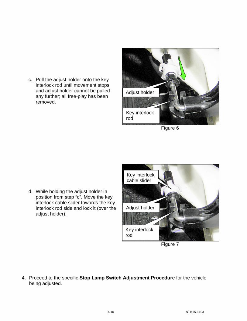
c. Pull the adjust holder onto the key interlock rod until movement stops and adjust holder cannot be pulled any further; all free-play has been removed.
d. While holding the adjust holder in position from step “c”, Move the key interlock cable slider towards the key interlock rod side and lock it (over the adjust holder).
Adjust holder
Key interlock rod
Figure 6
Key interlock cable slider
Figure 7
Adjust holder
Key interlock rod
4. Proceed to the specific Stop Lamp Switch Adjustment Procedure for the vehicle
being adjusted.
4/10 NTB15-110a

Stop Lamp Switch Adjustment Procedure
NOTE: The following steps are performed without the brake pedal depressed. NV200
Adjust the stop lamp switch:
1. Turn the stop lamp switch (black switch, Figure 8) 45° counterclockwise to unlock.
Stop lamp switch
Unlock direction
Figure 8
2. While unlocked, gently push the stop lamp switch until its black plastic body contacts the brake pedal arm (Figure 9).
3. While holding the stop lamp switch against the brake pedal arm turn the switch 45° clockwise to lock in place.
NOTE: The “brake pedal arm” in the above steps is listed as the “brake pedal bracket” in the ESM.
4. Confirm the clearance between brake pedal arm and black plastic body of the stop lamp switch (Figure 9); readjust as necessary.
Measure clearance here
Stop lamp switch
Figure 9
Brake pedal arm
Clearance: 0.74 – 1.96 mm (0.0291 – 0.0772 in)
IMPORTANT: After adjusting the stop lamp switch, confirm that the stop lamps come ON while the brake pedal is depressed, and then go out when released.
If the stop lamps do not come ON or go out after adjusting switch, recheck stop lamp switch adjustment.
5. Proceed to Inspection after Adjustments on page 9.
5/10 NTB15-110a

Sentra
Figure 10
Figure 11
Measure clearance here
Unlock direction
Stop lamp switch
Adjust the stop lamp switch:
1. Turn the stop lamp switch (right side switch, Figure 10) 45° counterclockwise to unlock.
2. While unlocked, gently push the stop lamp
switch until its plastic body contacts the brake pedal arm (Figure 11).
3. While holding the stop lamp switch against the brake pedal arm turn the switch 45° clockwise to lock in place.
NOTE: The “brake pedal arm” in the above steps is listed as the “brake pedal bracket” in the ESM.
4. Confirm the clearance between brake pedal arm and plastic body of the stop lamp switch (Figure 11); readjust as necessary.
Clearance: 0.74 – 1.96 mm (0.0291 – 0.0772 in)
Brake pedal arm
Brake pedal arm
Stop lamp switch
IMPORTANT: After adjusting the stop lamp switch, confirm that the stop lamps come ON while the brake pedal is depressed, and then go out when released.
If the stop lamps do not come ON or go out after adjusting switch, recheck stop lamp switch adjustment.
5. Proceed to Inspection after Adjustments on page 9.
6/10 NTB15-110a

Versa Sedan and Versa Note
Figure 12
Figure 13
Stop lamp switch
Unlock direction
Measure clearance here
Adjust the stop lamp switch:
1. Turn the stop lamp switch (left side switch, Figure 12) 45° counterclockwise to unlock.
2. While unlocked, gently push the stop
lamp switch until its black plastic body contacts the brake pedal lever (Figure 13).
3. While holding the stop lamp switch against the brake pedal lever turn the switch 45° clockwise to lock in place.
4. Confirm the clearance between brake pedal lever and black plastic body of the stop lamp switch (Figure 13); readjust as necessary.
Clearance: 0.2 – 1.96 mm (0.008 – 0.0772 in)
Brake pedal lever
Stop lamp switch
IMPORTANT: After adjusting the stop lamp switch, confirm that the stop lamps come ON while the brake pedal is depressed, and then go out when released.
If the stop lamps do not come ON or go out after adjusting switch, recheck stop lamp switch adjustment.
5. Proceed to Inspection after Adjustments on page 9.
7/10 NTB15-110a

Rogue
Figure 14
Figure 15
Clearance: 0.2 – 1.96 mm (0.008 – 0.0772 in)
Adjust the stop lamp switch:
1. Turn the stop lamp switch (bottom switch, Figure 14) 45° counterclockwise to unlock.
2. While unlocked, gently push the stop lamp
switch until its plastic body contacts the brake pedal arm (Figure 15).
3. While holding the stop lamp switch against the brake pedal arm turn the switch 45° clockwise to lock in place.
NOTE: The “brake pedal arm” in the above steps is listed as the “brake pedal stopper bracket” in the ESM.
Brake pedal arm
4. Confirm the clearance between brake pedal arm and plastic body of the stop lamp switch (Figure 15); readjust as necessary.
Unlock direction
Stop lamp switch
Stop lamp switch
Measure clearance here
IMPORTANT: After adjusting the stop lamp switch, confirm that the stop lamps come ON while the brake pedal is depressed, and then go out when released.
If the stop lamps do not come ON or go out after adjusting switch, recheck stop lamp switch adjustment.
5. Proceed to Inspection after Adjustments on next page.
8/10 NTB15-110a
Inspection after Adjustments 1. After performing key interlock cable and stop lamp switch adjustments, confirm the
following items:
a) “Control Device”
i) To operate the “control lever” from “P” position to other ranges under ignition ON state, the lever is not operable unless the brake pedal is stepped on.
ii) In other ranges, it is operable regardless of the brake pedal. At “P” position, the
“control lever” is not operable under any state other than ignition ON.
b) “Steering Lock”
i) The key can be removed only when the “control lever” is in the “P” position. 2. Turn the ignition OFF, and then disconnect the passenger air bag indicator lamp.
IMPORTANT: If the ignition is ON or turned ON when the passenger air bag indicator lamp is disconnected, supplemental restraint system (SRS) related DTCs may set and be permanently stored in the air bag diagnosis sensor unit.
3. Reassemble the vehicle in reverse order of disassembly. 4. After turning the ignition ON or starting the engine, make sure the supplemental air bag
and front passenger air bag indicator lights turn OFF after approximately seven (7) seconds.
The front passenger seat should be empty before performing step 4. 5. Use CONSULT-III plus to erase any DTCs caused by this repair.
9/10 NTB15-110a

CLAIMS INFORMATION
Submit a Primary Operation (PO) type line claim using the following claims coding:
MODEL DESCRIPTION OP CODE SYM DIA FRT
Sentra
Adjust Key Interlock Cable and Brake Switch
JX41AA ZE 32
0.5
Versa Sedan 0.3
Versa Note 0.3
NV200 1.0
Rogue 0.4
10/10 NTB15-110a
Recommended