Joints in Steel Construction: Simple Connections (Publication P212, 2002)
Corrigendum 1, October 2002
Tying Capacity of Fin Plate Connections with Single Line of Bolts. The values of tying capacity given in Table H.27 (pages 410 to 414) and Table H.29 (pages420 to 424) should be amended to values that are the lesser of the tabulated values and theshear capacity of the bolt groups. The shear capacity of the bolt group = n.Ps where n is thenumber of bolts and Ps is the shear capacity per bolt (= 91.9 kN for M20, grade 8.8 bolt fromTable H.49). The reason for this change is that, as stated in Table H.24, the tabulated tying capacities for fin plate connections were based on the minimum values from Checks 11 (i), 11 (ii), 12(i) and 12(ii). None of these checks relate to the shear capacity of the bolt group. Where there is a single line of bolts, the shear capacity of the bolt group may beless than the tabulated tying capacity.
Also, when carrying out the full design procedure (in accordance with Section 6.5) an additional check for "structural integrity" should be made for the shear capacity of the bolt group. This additional check, which may be referred to as Check 13, is: Tie force ≤ n.Ps. In practice these changes will only be of significance in the unusual case when the tie force is greater than the shear force on the beam.
©2002 The Steel Construction Institute SCI P212 (Corrigendum 1, Oct 2002)

The Steel Construction Institute develops and promotes the effective use of steel in construction. It is anindependent, membership based organisation.
SCI’s research and development activities cover many aspects of steel construction including multi-storeyconstruction, industrial buildings, light gauge steel framing systems and modular construction, developmentof design guidance on the use of stainless steel, fire engineering, bridge and civil engineering, offshoreengineering, environmental studies, value engineering and development of structural analysis systemsand information technology.
Membership is open to all organisations and individuals who are involved with the use of steel inconstruction. Members include designers, contractors, suppliers, fabricators, academics, and governmentdepartments in the United Kingdom, elsewhere in Europe and in countries around the world. The SCI isfinanced by subscriptions from its members, and by revenue from research contracts, consultancy services,publication sales and course fees.
The benefits of corporate membership include access to an independant specialist advisory service andfree initial copies of SCI publications as soon as they are produced. A membership Pack is available onrequest from the Membership Manager.
The Steel Construction Institute, Silwood Park, Ascot, Berkshire, SL5 7QN,Telephone: +44(0) 1344 623345 Fax: +44(0) 1344 622944Email: [email protected]
Web site: www.steel-sci.orgVisit: www.steelbiz.org - the 24x7 online technical information system for steel design and construction
The British Constructional Steelwork Association Limited
The British Constructional Steelwork Association Limited (BCSA) was formed in 1906 and is the nationalorganisation for the constructional steelwork industry: its Member companies undertake the design, fabricationand erection of steelwork for all forms of construction in building and civil engineering. Associate Membersare those principal companies involved in the purchase, design or supply of components, materials, services,etc. related to the industry. Corporate Members are clients, professional offices, educational establishmentsetc., which support the development of national specifications, quality, fabrication and erection techniques,overall industry efficiency and good practice.
The principal objectives of the Association are to promote the use of structural steelwork; to assist specifiersand clients; to ensure that the capabilities and activities of the industry are widely understood and to providemembers with professional services in technical, commercial, contractual and quality assurance matters. Theservices provided by BCSA work both for the overall benefit of the industry and for the direct benefit ofindividual companies.
A current list of members and a list of current publications and further membership details can be obtained from:
The British Constructional Steelwork Association Limited,4 Whitehall Court, Westminster, London SW1A 2ES.Telephone: +44 (0)20 7839 8566, Fax: +44 (0)20 7976 1634.Email:[email protected] site: www.steelconstruction.org
The Steel Construction Institute
The Steel Construction InstituteSilwood ParkAscotSL5 7QN
Telephone: 01344 623345Fax: 01344 622944
Jointly published by:
Joints in Steel ConstructionSimple Connections
Publication P212
The British Constructional SteelworkAssociation Limited4 Whitehall CourtLondon SW1A 2ES
Telephone: 020 7839 8566Fax: 020 7976 1634
ii
© The Steel Construction Institute and The British Constructional Steelwork Association 2002
Apart from any fair dealing for the purposes of research or private study or criticism or review, as permitted underThe Copyright, Designs and Patents Act 1988, this publication may not be reproduced, stored, or transmitted, in anyform or by any means, without the prior permission in writing of the publishers, or in the case of reprographicreproduction only in accordance with terms of the licences issued by the UK Copyright Licensing Agency, or inaccordance with the terms of licences issued by the appropriate Reproduction Rights Organisation outside the UK.
Enquiries concerning reproduction outside the terms stated here should be sent to the publishers, at the addressesgiven on the title page.
Although care has been to ensure, to the best of our knowledge, that all data and information contained herein areaccurate to the extent that they relate to either matters of fact or accepted practice or matters of opinion at the timeof publication, The Steel Construction Institute, The British Constructional Steelwork Association Limited, the authorsand any other contributor assume no responsibility for any errors in or misinterpretations of such data and/orinformation or any loss or damage arising from or related to their use.
Publications supplied to Members of SCI and BCSA at a discount are not for resale by them.
Publication Number: P212 ISBN 1 85942 072 9
British Library Cataloguing-in-Publication Data.
A catalogue record for this book is available from the British Library.

iii
FOREWORD
This publication is one of a series of "Green Books" that cover a range of steelwork connections. It provides design
guidance for structural steelwork connections for use in buildings designed by the "Simple Method" i.e. braced frames
where connections carry mainly shear and axial loads only.
Other books in the series are:
Joints in steel construction: Moment connections (P207/95), which provides design guidance for connections which in
addition to shear and axial loads, are required to resist bending moments.
Joints in steel construction: Composite connections (P213/98), which provides design guidance for moment resisting
composite end plate connections.
Design guidance for a range of simple connections was originally published in two separate volumes entitled
Joints in simple construction: Volume 1: Design Methods (P205) and Volume 2: Practical Applications (P206/92). Availability
of further research has enabled this publication to include design guidance for a wider range of simple joints and, at
the same time, the opportunity has been taken to combine the two volumes.
The major additions to the previous publications (Volumes 1 and 2) are:
• lnclusion of design guidance for bolted connections to hot finished structural hollow sections using Flowdrill
or Hollo-Bolts.
• Use of fin plates for deep beams.
• Inclusion of design procedures for double lines of bolts in double angle web cleats and fin plates.
• Improved structural integrity guidance.
• Use of fully threaded bolts.
• Inclusion of bracing connections.
• Inclusion of slotted and kidney shaped holes.
This publication was produced by the SCI/BCSA Connections Group, which was established in 1987 to bring together
academics, consultants and steelwork contractors to work on the development of authoritative design guides for
structural steelwork connections.

iv
ACKNOWLEDGEMENTS
This publication has been prepared with guidance from the SCI/BCSA Connections Group consisting of the followingmembers:
David Brown The Steel Construction Institute
Mike Fewster Billington Structures Ltd
Peter Gannon Watson Steel Structures
Dr Craig Gibbons Arup (Hong Kong)
Eddie Hole* Corus Tubes
Alastair Hughes Arup
Abdul Malik* The Steel Construction Institute
Dr David Moore Building Research Establishment Ltd
Prof David Nethercot Imperial College of Science & Technology
Dr Graham Owens The Steel Construction Institute (Chairman)
Alan Pillinger Bourne Steel Ltd
Alan Rathbone C.S.C.(UK) Ltd
Roger Reed Thomas William Lench Ltd
John Rushton Peter Brett Associates
Prof Susanta Sarker
Colin Smart Corus Construction and Industrial
Gary Simmons William Hare Ltd
Peter Swindells Caunton Engineering Ltd
Mark Tiddy Cooper and Turner
Andrew Way * The Steel Construction Institute
Phil Williams The British Constructional Steelwork Association Ltd
* Editorial Committee members.
The editorial committee acknowledges the original work leading to Joints in simple construction Vol. I (P205)
and Vol.2 (P206/92) which this publication has incorporated.
Assistance in preparing this combined and extended edition was provided by Peter Allen (formerly BCSA). The text and
graphics were produced by Richard Stainsby. The connection capacity tables were produced by Nina Knudsen and
Jiri Mares of SCI.
The work was partially funded by the Construction, Innovation & Research
Management Division of Department of Trade and Industry (DTI) under the
Partners in Innovation (PII) initiative.
Sponsorship was also received from Corus plc.
References to BS 5950-1:2000 have been made with the permission of British Standards Institution, BSI CustomerServices, 389 Chiswick High Road, London, W4 4AL
University of Abertay Dundee

v
Double Angle Web CleatsPages 10 - 81
Bracing ConnectionsPages 290 -295
Columns BasesPages 264 - 289
Kidney ShapedSlot Connections
Page 295
Flexible End PlatesPages 82 - 149
Fin PlatesPages 150 - 207
Column SplicesPages 208 - 263
PICTORIAL INDEX

vi
CONTENTS
PAGE
Foreword iii
Acknowledgements iv
Pictorial Index v
1. Introduction
1.1 About this design Guide 1
1.2 Connection considerations 1
1.3 Exchange of information 2
1.4 Costs 3
1.5 Major symbols 4
2. Standardised Connections
2.1 The benefits of standardisation 5
2.2 Components 6
2.3 Geometry 7
3. Beam-to-Beam and Beam-to-Column Connections
3.1 Introduction 9
4. Double Angle Web Cleats
4.1 Introduction 10
4.2 Practical considerations 11
4.3 Recommended geometry 11
4.4 Design 13
4.5 Design Procedures 14 - 32
4.6 Worked Examples 33
Example 1 - Double Angle Cleats - Beam to Beam 34 - 51
Example 2 - Double Angle Cleats - Beam to UC column web - Structural Integrity 52 -59
Example 3 - Double Angle Cleats - Beam to RHS column using Flowdrill 60 - 68
Example 4 - Double Angle Cleats - Beam to RHS column using Hollo-Bolt 69 - 79
Example 5 - Double Angle Cleats - Stability of unrestrained notched beam 80 - 81
5. Flexible End Plates
5.1 Introduction 82
5.2 Practical considerations 82
5.3 Recommended geometry 83
5.4 Design 83
5.5 Design Procedures 86 - 101
5.6 Worked Examples 102
Example 1 - Flexible End Plates - Beam to Beam 101-114
Example 2 - Flexible End Plates - Beam to UC column web - Structural Integrity 115-122
Example 3 - Flexible End Plates - Beam to RHS column using Flowdrill 123-134
Example 4 - Flexible End Plates - Beam to RHS column using Hollo-Bolt 135-149
vii
CONTENTS (Continued)
PAGE
6. Fin Plates
6.1 Introduction 150
6.2 Practical considerations 151
6.3 Recommended geometry 153
6.4 Design 153
6.5 Design Procedures 155 - 173
6.6 Worked Examples 174
Example 1 - Fin Plates - Beam to Beam 175 - 186
Example 2 - Fin Plates - Beam to UC column web - Structural Integrity 187 - 192
Example 3 - Fin Plates - Beam to RHS column 193 - 201
Example 4 - Fin Plates - Beam to CHS column 202 - 207
7. Column Splices
7.1 Introduction 208
7.2 Practical considerations 209
7.3 Recommended geometry 210
7.4 Design 211
7.5 Design Procedures cover-plate splices for I section columns - (Bearing type) 212 - 218
7.6 Design Procedures cover-plate splices for I section columns - (Non-Bearing type) 219 - 226
7.7 Design Procedures RHS End-plate splices in tension 227 - 232
7.8 Design Procedures CHS End-plate splices in tension 233 - 238
7.9 Worked Examples 239
Example 1 - column splices - UC Bearing splice 240 - 242
Example 2 - column splices - UC Bearing splice (net tension developed) 243 - 253
Example 3 - column splices - UC Non-Bearing splice 247 - 253
Example 4 - column splices - RHS tension splice 254 - 258
Example 5 - column splices - CHS tension splice 259 - 263
8. Column Bases
8.1 Introduction 264
8.2 Practical considerations 265
8.3 Recommended geometry 267
8.4 Design 268
8.5 Design Procedures 269 - 272
8.6 Worked Examples 273
Example 1 Column base design - UC column - effective area method 274 - 277
Example 2 Column base design - UC column - effective area with 'overlap' 278 - 281
Example 3 Column base design - RHS column - effective area method 282 - 285
Example 4 Column base design - CHS column - effective area method 286 - 289

viii
CONTENTS (Continued)
PAGE
9. Bracing Connections
9.1 Introduction 290
9.2 Design considerations 290
9.3 Kidney shaped slot connections 295
10. Special Connections
10.1 Introduction 297
Table 10.1 Beams at different levels 298-299
Table 10.2 Skewed connections 300-301
Table 10.3 I Beam to RHS column 302
Table 10.4 Parallel Beams to RHS column 302
Table 10.5 Off-grid connections 303-304
Table 10.6 Column splices 305
Table 10.7 Column bases in braced bays 305
11. REFERENCES 306-309
12. BIBLIOGRAPHY 310-312
APPENDICES 313
Appendix A Structural integrity 314-316
Appendix B Large displacement analysis - Double Angle Web Cleats 317-321
Appendix C Large displacement analysis - Flexible End Plate 322-324
Appendix D Design for prying when resisting tying forces 325-326
Appendix E Base plate design (BS 5950: Part1:1990) method) 327-328
Appendix F Thermal drilling of RHS 329-330
Appendix G Hollo-Bolt jointing of RHS 331-332
Appendix H Capacity Tables, Dimensions for Detailing (Yellow Pages)and General Data 333

1
1. INTRODUCTION
1.1 ABOUT THIS DESIGN GUIDE
This guide provides procedures for designing connectionsin steel-framed structures in accordance with therecommendations of BS 5950–1:2000[1]. It uses the Simpledesign method described in clause 2.1.2.2. of the Code.Connections between universal beams and universalcolumns are included and between universal beams andhot finished structural hollow section columns using theFlowdrill and Hollo-Bolt systems. Designs are providedfor:
(a) Beam-to-beam and beam-to-column connections• Double angle web cleats (DAC)• Flexible end plates (FEP)
• Fin plates (FP)
(b) Column splicesBolted splices which may be cover plate or end platetype.
(c) Column basesSlab bases welded to the column shaft.
(d) Bracing connectionsAngles and hollow sections connected to other mainmembers via a gusset plate. Types of suitableconnections to facilitate site bolted assembly areprovided with design considerations.
(e) Special connectionsSpecial connections for cases when members donot align on a common centreline, at different levelsor at a skew angle. Some guidance is given on thesespecial connections.
Steel gradesSteel grades are designated by European classificationscurrently used by the steel construction industry inBS EN Specifications relating to steel and now adopted inBS 5950–1:2000[1]. Reference is only made to the strengthrequirements to which, for completeness, should beadded the impact (or sub grade) designation. Table 1.1shows the basic material grade now used and thedesignation previously employed.
Design proceduresIndividual design procedures are included to check allrelevant elements, welds and bolts within the connection.The procedures start with the detailing requirements(joint geometry) then presents the checks for each stageof the load transition through the complete connectionincluding welds, plates, bolts and the section webs orflanges as appropriate. The capacity checks on sections,welds and bolts are all based on BS 5950–1:2000[1].
The design guidance for hollow section columns is atpresent restricted to hot finished structural hollow sections.
Capacity tablesWithout access to suitable software, designing simpleconnections can be a long and tedious process. To helpovercome this problem, capacity tables for standardconnections are provided in the yellow pages of thisguide.
The capacity tables have been arranged so that thedesigner can simply select a connection and, with theminimum of calculation, check whether it has sufficientcapacity. Tables can also aid designers with initial memberselection. The tables use rolled sections to BS 4[2],BS EN 10210[3] and BS EN 10219[4] but other profilesmay be used, referring to the design procedures wherenecessary.
A key aim in producing capacity tables is the standardisationof bolts and fittings, a concept that is widely recognised asimproving the efficiency of the steelwork industry.
Design examplesWorked examples illustrating the design procedures andthe use of capacity tables are also included.
1.2 CONNECTION CONSIDERATIONS
ClassificationIn keeping with the design methodology of the overallstructure, simple connections are those which complywith the following five conditions:
(i) are assumed to transfer the design shear reaction onlybetween members
(ii) are incapable of transmitting significant momentswhich might adversely affect members of the structure
(iii) are capable of accepting the resulting rotation
(iv) provide the directional restraint to members whichhas been assumed in the member design
(v) have sufficient robustness to satisfy the structuralintegrity requirements.
Table 1.1 Steel grades
BS 5950–1:2000 Previous editions of BS 5950
S275 Design Grade 43
S355 Design Grade 50

2
Structural integrityIt is a recommendation of BS 5950–1:2000[1], clause2.4.5.2 that all building frames be effectively held togetherat each principal floor and roof level. Tests carried out atthe Building Research Establishment[5] and described inAppendix A show that connections designed and detailedin accordance with this guide, will generally be capable ofcarrying the basic 75 kN tying force requirement.
Clause 2.4.5.3 recommends that where BuildingRegulations require that certain buildings should bespecially designed to avoid disproportionate collapse, thetying force should be increased above the minimum75kN. The increased tying force is normally equal to theend reaction, but can sometimes be less depending onhow the floor beams are arranged.
Appendices A to D give information on the behaviour andmethodology for designing connections to resist tying forces.
Stability during erectionThe Steelwork Contractor is usually responsible for stabilityof the structure during erection.
In simple construction, stability against lateral loading isgenerally provided by the floor and roof acting as stiffdiaphragms to transmit loads horizontally to points ofsway resistance such as vertical bracings, shear walls or liftcores. However, during erection there will invariably bestages when the floors or shear walls are incomplete andit is vital that stability is maintained at all times.
In assessing these temporary cases, consideration must begiven to many factors such as:
• the wind loads on the unclad structure[6]
• the stiffness of the vertical frames arising from anyconnection and base fixity
• the ability of partially finished floors to providediaphragm action.
As most of the connections in this guide have limitedrotational stiffness, it may be necessary to arrange theconstruction so that the floors are decked out in sequenceand temporary bracing provided. This will provide bothstability to the framework and allow any concreteplacement to keep up with the steelwork erection, thuspreventing delays to the construction programme. Ideally,any temporary bracing will be in the form of wires withturnbuckles or other tensioning systems rather than steelangles or flats. Tensioned wires have the added benefit ofhelping to plumb the frame as well as being easier toremove on completion.
Connections typesThe selection of beam end connections can often be quiteinvolved. The relative merits of the three connection typesincluded in this guide are summarised in Table 1.2.
Bearing connectionsWhen designing column splices and bases it should benoted that the bearing connections are suitable in mostsituations. They are less expensive to fabricate and quickerto erect than the non-bearing types. A Steelwork Contractorwith reasonable quality sawing equipment can achievethe necessary level of accuracy for a bearing connection.
Composite floorsIt is recognised that interaction with a composite floor willaffect the behaviour of a simple connection. Commonpractice is to design such connections without utilisingthe benefits of the continuity of reinforcement throughthe concrete slab. However, Joints in steel construction:Composite connections[7], enables reinforcement continuityto be allowed for in providing relatively simple flush end-plate connections with substantial moment capacity.
1.3 EXCHANGE OF INFORMATION
The design of the frame and its connections is usuallycarried out in one of the following ways:
(i) The frame is designed by the Consulting Engineerand the connections are designed by the SteelworkContractor
(ii) The frame and the connections are designed by theSteelwork Contractor.
(iii) The frame and its principle connections are designedby the Consulting Engineer.
Where method (i) is in operation, care must be taken toensure that design requirements for the connections areclearly defined in the contract and on the design drawings.
The National Structural Steelwork Specification for BuildingConstruction[8] gives guidance on the transfer of informationand there will be great benefits if this is observed. Thefollowing items should be considered a minimum:
• a statement describing the design concept
• drawings, or equivalent electronic data, showing thesize, grade and position of all members
• the design standards to be used
• the forces required to be transmitted by each connection
• whether the loads shown are factored or unfactored
• requirements for any particular type of fabricationdetail and/or restriction on the type of connection to beused.
Introduction - Exchange of Information

3
Table 1.2 Relative merits of beam end connection types
Double angle Flexible end Fin plate web cleats (DAC) plate (FEP) (FP)
DesignShear capacity - percentage Up to 50% Up to 75% Up to 50%of beam capacity Up to 75% with two vertical 100% with full depth plates Up to 75% with two vertical
lines of bolts lines of bolts
Tying capacity Good Fair, but non-standard plates Goodmay be required
Specialconsiderations
Skewed Joints Unsuitable Fair Good
Beams eccentric to columns Poor Fair Good
Connection to column webs Fair Good FairStandard cleats unsuitable To facilitate erection, flangefor 152 or 203 UC’s stripping may be required.
Sfiffening may be requiredfor long fin plates (Figure 6.7)
Fabrication andtreatment
Fabrication Good Good GoodNo welding required Stiffening may be required
for long fin plates (Figure 6.8)
Surface treatment Fair Good GoodComponents treated separatelybefore assembly
ErectionEase of erection Fair Fair Good
Difficult for two-sided Difficult for two-sidedconnections connections
Site adjustment Good Fair Fair
Temporary stability Fair Fair Fair
1.4 COSTS
Simple connections are invariably cheaper to fabricatethan moment resisting connections, because they providea significant degree of simplicity and standardisation.
Giving specific guidance on costs is difficult, as SteelworkContractor's workmanship rates can vary considerablyand are dependant upon the level of investment in plantand machinery. However, the designer’s and detailer’smain objective must be to reduce the work content. Thematerial cost for fittings and bolts are small comparedwith workmanship costs. In a typical fabrication
workshop the cost of fabrication of connections maybe 30% to 50% of the total fabrication cost.
The real costs come from the time taken to design theconnection, detail it, make the fittings, mark out thegeometry, drill the holes and complete the welding andtesting. These costs can be minimised by adoptingstandard connections, as discussed in Section 2, and byearly consultation with the appointed SteelworkContractor. For further information see Design forManufacture Guidelines [9]
Introduction - Costs

4
1.5 MAJOR SYMBOLS
The major symbols used in this Guide are listed below for reference purposes. Other are described where used.
As Shear area of bolt
a Effective throat of weld
B Width of section (Subscript c or b refers to column or beam)
D Depth of section (Subscript c or b refers to column or beam)
Dh Hole diameter
d Depth of web between fillets or diameter of a bolt
e End distance
Fs Shear Force in bolt
Fv Vertical reaction
g Gauge (Transverse distance between bolt centrelines)
P Capacity (Subscripts c - compression, b - bearing, s - shear)
p Bolt spacing (‘pitch’)
py Design strength of steel
r Root radius of section
s Fillet weld leg length
T Thickness of flange
t Thickness of web
tp Thickness of plate
Us Ultimate tensile strength
Z Elastic modulus (Subscript b refers to bolt group modulus)
Lengths and thicknesses stated without units are in millimetres.
Introduction - Major Symbols

5
2. STANDARDISED CONNECTIONS
• The use of a few standard flats or angles for fittingswhich:
– improves availability
– leads to a reduction in material costs
– reduces buying, storage, and handling time.
• The use of one grade and diameter of bolt in a limitedrange of lengths which:
– saves time changing drills or punches in the shop
– leads to faster erection and fewer errors on site.
• The use of small, single pass fillet welds which:
– avoids the need for any edge preparation
– reduces the amount of non-destructive testingrequired.
In practice, steel structures can be complex and there willbe times when the standard connections presented hereare not suitable. However, even in these cases it will still bepossible to adopt some of the general principles ofstandardisation such as limiting the range of fittings,sections and bolt sizes.
A summary of the recommended components adopted forthis Guide is shown in Table 2.1.
2.1 THE BENEFITS OF STANDARDISATION
In a typical braced multi-storey frame the connectionsmay account for less than 5% of the frame weight, and yetprobably 30% or more of the total cost. Efficientconnections will therefore have the lowest detailing,fabrication and erection labour content - they will notnecessarily be the lightest.
A problem facing the connection designer today is thebewildering range of options he has in selecting:
• the type of connection
• grades and sizes of fittings
• bolt grades, sizes and lengths
• weld types and sizes
• the geometry to adopt.
In preparing this Guide, one of the main objectives hasbeen to carry out a rationalisation and to recommendstandards in each of the above areas. This procedure leadsto a standard connection where the fittings, bolts, weldsand geometry are fully defined.
The benefits of this approach are as follows:
• A reduction in the number of connection types which:
– leads to a better understanding of their costand performance by all sides of the industry
– encourages the development of design aidsand computer software.
Component Preferred Option Notes
Fittings Material of grade S275Limited range of standard flats and angles – (see Table 2.2)
Bolts M20 grade 8.8 Bolts – Some heavily loaded connectionsmay need larger diameter bolts
– Foundation bolts M24 grade 4.6
Holes 22mm diameter punched or drilled, or – 26mm dia for M24 bolts22mm x 26mm slottted holes made by: – 6mm oversize for Foundation– punching in one operation bolts– formed by drilling two holes and completed by cutting– machine operated flame cutting
Welds Fillet welds with E35 electrodes – larger welds may be needed for6mm or 8mm leg length some column bases
Table 2.1 Recommended components

6
2.2 COMPONENTS
FittingsWith the exception of column bases and some componentsfor heavy column splices that have to be cut from plate,fittings for simple connections are normally manufacturedfrom standard flats or angles.
Table 2.2 lists the recommended range of fitting sizeswhich have been adopted throughout this Guide.
There can be problems obtaining flats and angles in highergrade steel (S355) and for this reason it is recommendedthat all fittings material should be of grade S275. Theadoption of one grade of steel for fittings also assists theSteelwork Contractor with the control of his stock.
BoltsStructural bolting practice for both rolled section membersand hollow section members is based predominantly onnon-preloaded bolts of strength grades 4.6 and 8.8 usedin 2mm clearance holes. Such bolts are termed ordinarybolts and are specified in BS 4190[10] and other standards(see Table 2 in BS 5950-2: 2001[1]).
Grade 8.8 bolts to BS 4190 are commonly available andare recommended for all main structural connections,with the standard bolt being 20mm diameter. Grade 4.6bolts are generally used only for fixing lighter componentssuch as purlins or sheeting rails, when 12mm or 16mm boltsmay be adopted. For holding down bolts, see Section 8.2.
There may be situations, for example a column splicesubjected to large load reversals in a braced bay, where theengineer feels that joint slip is unacceptable. In these casesthe general grade high strength friction grip bolt toBS 4395[11] should be used.
The mixing of different grades of bolt in the same diameteron any one project should be avoided.
In order to avoid the question on site of acceptability ofthreads in the shear plane.The determination of bolt shearcapacity should assume that the threads are in the shearplane. All the capacity tables and examples in this Guidefollow this assumption.
Fully threaded boltsCommon practice in the past has been to use bolts with ashort thread length, i.e. 1.5d, and to specify them in 5mmlength increments. This can result in an enormous numberof different bolts, which is both costly to administer andcan prevent rapid erection.
It is recommended that fully threaded bolts (technicallyknown as screws) be used as the industry standard. Theycan be provided longer than necessary for a particularconnection and can therefore dramatically reduce therange of bolt lengths specified. For example, the M20 x60mm long grade 8.8 fully threaded bolt has been shownto be suitable for 90% of the connections in a typical multi-storey frame. Table 2.3 shows a rationalised range of sizes.
Research has demonstrated that the very marginal increasein deformation with fully threaded bolts in bearing has nosignificant effect on the performance of a typical joint. Inthe specific instances where this additional deformationmight be of concern, it is normal and recommendedpractice to use preloaded (HSFG) bolts. These can be usedfor example in tension and compression splices where thebolts are in shear/bearing or in column splices where thecolumn ends are not in bearing. A paper by Owens[12]
gives the background to the use of fully threaded bolts inboth tension and shear conditions.
Table 2.2 Recommended sizes of flats and angles
FITTINGS LOCATION
Type Size Thickness Web End Finmm mm Cleat Plate Plate
Flat 100 10 •
150 8 •
150 10 •
200 10 •
Angle 90 x 90 10 •
150 x 90 10 •
Table 2.3 Recommended sizes - fully threaded bolts
Grade Diameter Length (mm)
*4.6 M12 25 - -
*4.6 M16 30 - -
8.8 M16 30 45 -
8.8 M20 45 60 -
8.8 M24 70 85 100
* Recommended only for use in fixing cold rolled purlins and rails.
Fully threaded fasteners (4.6 and 8.8 Screws) should be specified to BS 4190: 2001
Standardised Connections - Components

7
Bolting to Rectangular Hollow SectionsBolted connections to rectangular hollow sections (RHS)using the Flowdrill or Hollo-Bolt systems may also bestandardised using M20 8.8 bolts but the bolt lengthmust be chosen to suit the fastener system.
For further information on Flowdrill system, see Appendix Fand Tables H.55a, H.55b and H.60.
For further information on Hollo-Bolt system, see Appendix Gand Tables H.56 and H.61.
HolesNormal practice is for holes to be drilled in main sectionsand either punched or drilled in fittings. Hole sizes shouldbe as follows:
Ordinary or HSFG Bolts ≤ 24mm dia: bolt dia + 2mm Ordinary or HSFG Bolts > 24mm dia: bolt dia + 3mm
Holding down bolts: bolt dia + 6mm
With slab bases thicker than 60mm, the normal clearanceof 6mm is often insufficient to allow the necessaryadjustment and this may need to be increased.
Holes of 22mm or 26mm can be safely punched throughgrade S275 material up to 12mm thick, which covers allthe standard fittings for beam end connections in thisGuide. Further guidance on hole punching can be foundin the National Structural Steelwork Specification[8].
As will be seen in Section 4, which deals with double angleweb cleats, short slotted holes 22mm dia x 26mm longmay be used in certain instances. This hole can bepunched full size in a single operation.
WeldsAll the welds used for connections in this Guide are simplefillet welds carried out by a metal arc process in accordancewith BS EN 1011–1[13].
The standard leg length is 6mm or 8mm, which can easilybe laid in a single run. Fillet welds of this size are generallyrecognised as being extremely reliable and will normallyneed little testing beyond the usual visual inspection.
2.3 GEOMETRYBeam notchesNotching is normally required for beam-to-beamconnections to enable the supported beam to frame intothe web of the supporting beam (see Figure 2.1).
The notch length should provide a nominal clearance of10mm from the edge of the supporting beam flange andwill vary depending on the width of the supporting beam,but should be kept to a minimum to avoid local stabilityproblems.
A standard top notch depth of 50mm is recommendedand this will be adequate for all but the largest UB and UCsections. Apart from encouraging the use of templates formarking out, the main benefit of a standard notch depthis that it allows the top row of bolts to be positioned aconsistent 90mm below the top of the beam - the normalreference point. Specific notch dimensions for a particularrolled section can be found in the dimension tables in theyellow pages.
If a hole is to be drilled at the root to form a radius, thenthis should be the standard 22mm diameter to avoidchanging drills. If the notch is to be cut square, then greatcare must be taken to avoid overcutting at the corner.Coping machines can usually cut the notch square or withany specified radius.
Flange trimsFor some beam to column web connections, the edges ofthe beam flanges may need to be trimmed as shown inFigure 2.2. The dimensions given make allowance for thebeam to swing down into position in the column web,clearing any bolt heads present from beams alreadyconnected to the column flanges.
This extra fabrication is obviously costly but can often beavoided by the careful selection of beam and columnsizes.
Figure 2.1 Beam notches
Column
Flange Trim (mm)
a b
356 UC 240 190
305 UC 195 160
254 UC 150 135
203 UC 110 110
152 UC 70 85
Figure 2.2 Flange Trims
Column Beam
a
b
tw2
Supporting beam
Supported beam
Clearance generally 10mmStandard topnotch depth50mm
Double notched beamSingle notched beam
Supported beam
Standardised Connections - Geometry

8
Flange chamfersOccasionally, when beams of different depths connectinto opposite sides of a column or beam web, the bottomflange of the smaller beam may clash with the boltsconnecting the deeper beam. To avoid using specialfittings with non-standard bolt pitches, a bottom flangechamfer can be used as shown in Figure 2.3. This chamferwill give adequate clearance for 20mm bolts at 90mm orgreater cross centres.
Vertical bolt layoutThe recommended vertical bolt layout using M20 boltsthat has been adopted throughout this Guide for all thebeam end connections is shown in Figure 2.4.
The tops of all fittings should be placed 50mm below thetop of the beam, which for beams with a standard notch,positions them flush with the notch top. This leads to thefirst bolt row being set down a constant 90mm from thetop of the beam, which is generally the setting out point.
For the fittings, a top and bottom edge distance to thebolts of 40mm has been used. This complies with the 2dminimum specified for fin plates in design procedureCheck 1(Section 6) and will prevent premature bearingfailure with M20 bolts.
Traditionally, the vertical bolt pitch ‘p’ has varied dependingon the type of connection, the section sizes, the materialgrades and the whim of the detailer! The standard pitchof 70mm which is recommended here has been found tobe an optimum solution which will satisfy most conditions.In practice the benefits of using a standard layout will faroutweigh any possible savings that might come fromvarying the pitch and omitting one or two rows of bolts.
Figure 2.4 Vertical bolt layout (beam end connections using M20 bolts)
914
UB
838
UB
762
UB
686
UB
610
UB
533
UB
457
UB
406
UB
356
UB
305
UB
254
UB
1110
98
76
544
32
90
Verticalpitch70mm
Note: Double notching may reduce the clearance to the bottom bolt
Bolt gaugeFor universal beams and columns the bolt gauge or crosscentres has been set at 90mm or 140mm for end platesand 100mm plus the beam web thickness (tw) for webcleats. These dimensions are designed to providereasonable clearance for bolt access as well as givingsufficient width for flexibility in end plate or web cleatconnections.
The bolt gauge may have to depart from these standarddimensions when connecting to the face of RHS sectionsbecause the gauge should be ≥ 0.3 x the RHS face width.
Figure 2.3 Flange chamfers
Bottom flange chamfer
X X
21
20mm
Section XX
Standardised Connections - Geometry

3. BEAM-to-BEAM and BEAM-to-COLUMN CONNECTIONS
3.1 INTRODUCTION
The design procedures which follow are suitable for eitherhand calculation or for the preparation of computersoftware.
Designing connections by hand is a laborious process andso a full set of capacity tables has been included in theyellow pages at the back of the guide.
Checking the strength of a simple connection involvesthree stages:
(1) Ensuring that the connection is detailed so that itdevelops only nominal moments which do notadversely affect the members or the connection itself.
(2) Identifying the load path through the connection i.e.from the beam to the supporting member.
(3) Checking the strength of each component, ensuringeach is capable of transferring the load from one partto the next.
For normal design there are ten design procedures requiredto check all the parts of a beam-to-beam or beam-to-column connection for vertical shear. A further six checksare required where structural integrity of the joint must beconsidered, (see Table 3.1).
The final six checks are associated with the structuralintegrity requirements of BS 5950-1:2000[1], wherebybeam/column connections must be able to resist lateraltying forces unless these forces are resisted by othermeans within the construction framework e.g. the floorslabs.
Table 3.1 summarises the design procedure checks requiredfor Double Angle Cleats (DAC), Flexible End Plates (FEP)and Fin Plates (FP). The design procedures are describedin Sections 4.5, 5.5 and 6.5.
Table 3.1 Design procedure for beam connections - summary table
Design procedure checks DAC FEP FP
Design model ✔ ✔ ✔
1 Recommended detailing practice ✔ ✔ ✔
2 Supported beam – Bolt group/Welds ✔ ✔ ✔
3 Supported beam – Connecting elements ✔ N/A ✔
4 Supported beam – Capacity at the connection ✔ ✔ ✔
5 Supported beam – Capacity at a notch ✔ ✔ ✔
6 Supported beam – Local stability of notched beam ✔ ✔ ✔
7 Unrestrained Supported beam – Overall stability of notched beam ✔ ✔ ✔
8 Supporting beam/column – Bolt group/Welds ✔ ✔ ✔
9 Supporting beam/column – Connecting elements ✔ ✔ N/A
10 Supporting beam/column – Local capacity ✔ ✔ ✔
11 Structural Integrity – Connecting elements ✔ ✔ ✔
12 Structural integrity – Supported beam ✔ ✔ ✔
13 Structural integrity – Tension bolt group/Welds ✔ ✔ N/A
14 Structural Integrity – Supporting column web (UC or UB) ✔ ✔ ✔
15 Structural integrity – Supporting column wall (RHS) ✔ ✔ ✔
16 Structural integrity – Supporting column wall (CHS) N/A N/A ✔
Notes: (i) The detail check is necessary where there is a tick (✔) in the column and is not appropriate where
indicated as N/A.
(ii) Checks on the bending, shear, local and lateral buckling capacity of a notched beam section are includedin this table as it is usually at the detailing stage that the requirement for notches is established, followingwhich, a check must be made on the reduced section.
9

10
4. DOUBLE ANGLE WEB CLEATS
4.1 INTRODUCTION
The double angle web cleat connection consists of a pairof angle cleats that are usually bolted to the supportedbeam web in the shop and the beam assembly is thenbolted to the supporting member (Beam, I column orRHS column) on site. Flowdrill or Hollo-Bolts are used forconnections to RHS columns, (see Figure 4.1).
The connection requires no welding and permits minorsite adjustment when using untorqued bolts in clearanceholes. However, it lacks flexibility in accommodatingbeam skews and there is difficulty in connecting intoshallow depth columns. It is also not as strong as anequivalent end plate connection.
The rotational capacity of the connection is governedprincipally by the deformation capacity of the angles and,to a lesser extent, by the slip between the connectedparts, (see Figure 4.2).
To minimise rotational resistance, the thickness of theangle cleats should be kept to a minimum and the boltcross-centres (or gauge) should be relatively large.
The connection moment is indeterminate but small andcan be neglected.
Figure 4.1 Double angle cleat. Beam-to-columnand beam-to-beam connections
Figure 4.2 Deformation of angle cleats
Untorqued bolts in clearance holes
Untorqued bolts in clearance holes
Flowdrill or Hollo-Bolt
Gauge, g
Rotation
g

11
4.2 PRACTICAL CONSIDERATIONS
Angle cleats are normally made by punching and cropping,with the holes in the beam and supporting membersusually being drilled.
One problem of detailing arises when beams with differentweb thicknesses frame into opposite sides of a supportingbeam or column web. For minor variations in the webthickness the normal bolt clearance holes will allow thebolt gauge to be set as normal. However, once thedifference is more than 3mm the gauge will usually be setat 100mm + tw based on the larger beam, and then cleatswith an increased back-mark made for the smaller beam.This obviously has its drawbacks and can lead to difficultieswith identification, especially if the back-mark in one legonly varies by, say, 2 or 3mm from the standard. A solutionto this problem is to use a short slotted hole, as describedbelow.
The slotted hole connectionA short slotted hole 22mm x 26mm long can be used inthe outstanding leg of the cleat as shown in Figure 4.3.
The bolt gauge in the support is set constant at 120mmand, by using cleats with a 55mm back-mark to the centreof the slot hole, beams with web thickness from 6mm to14mm can be accommodated. This caters for all the mainUBs with the exception of some sections at the top end ofthe range.
Although the bearing capacity of the cleat around theslotted hole is reduced (see BS 5950-1[1], clause 6.3.3.3)this check will rarely be critical.
When the connection is bolted up on site, washers shouldbe used over the slotted holes and the bolts firmlytightened. However, care must be taken not to use slottedholes in situations where vibration or dynamic loads arepresent which might lead to the possibility of joint slip.
ErectionThe double angle web cleat is a good connection in termsof its facility for site adjustment. The two sets of bolts areboth placed in clearance holes allowing slight adjustmentin two directions before the bolts are tightened. In additionto this, packs can be placed between the cleats and thesupported member if required.
With two sided connections that share a common set ofbolts, the shop bolts should be placed with heads inopposite directions in the connecting pair of beams andthe site bolts placed as shown in Figure 4.4. In some cases,it may be necessary to place the nut over the hole and turnthe bolt into the nut.
To facilitate the erection of a pair of larger beams it maybe necessary to provide some form of support duringerection. (See Figure 5.3 in Section 5)
4.3 RECOMMENDED GEOMETRY
The design procedures which follow set down a numberof recommended details that are intended to achieve therequired connection ductility.
When detailing the joint, the main requirements are asfollows:-
(i) the cleats are positioned close to the top flange inorder to provide positional restraint;
(ii) the cleats are at least 0.6 x the supported beamdepth in order to provide the beam with adequatetorsional restraint;
(iii) the cleats are relatively thin (8mm or 10mm);
(iv) the bolts in the supporting member are at reasonablecross centres (100mm + beam web thickness).
The first two requirements ensure that in those caseswhere the beam is laterally unrestrained, it can be designedwith an effective length of 1.0L. (BS 5950–1[1]: Table 13)
The last two requirements ensure adequate ductility toclassify as "simple connections".
These requirements, together with the standard geometrypresented in Section 2, have been used to create the‘standard connection’ shown in Figure 4.4.
Figure 4.3 Short slotted holes inDouble Angle Cleats
Double Angle Web Cleats - Recommended Geometry
26 slot
55 backmark
Enhancedclearance
120 cross centres of 22 dia holes
in support
22 dia hole in the supporting web

12
Beam-to-column Beam-to-beam
Recommended cleat size Vertical bolt lines
90 x 90 x 10 Angle 1
150 x 90 x 10 Angle 2
Bolts: M20 grade 8.8 in 22mm diameter holes
Cleats: Steel grade S 275, minimum length 0.6D
where D is depth of supported beam
Note: For the smaller UBs, up to 457mm deep, a 90 x 90 x 8mm anglecleat is sometimes used, and a case can also be made for using90 x 90 x 12mm angles for the heavier beams when shear in thecleat leg becomes critical. The use of 10mm thick cleats isrecommended for standard connections.
Figure 4.4 Standard double angle web cleat connections
Double Angle Web Cleats - Recommended Geometry
40
40
Holes @70 pitch
Flange chamfered to clear bolts
50
of bolt heads
headsBolt
Cross-centres(100+ t )mm
10 Projection
5050 50Boltheads
Note position
50
Backmark
w
w
t is the greater web thickness of the two beams connectingto the column web
Supporting column
Supportedbeam
Supporting beam
Supportedbeam
Supportedbeam
13
4.4 DESIGN
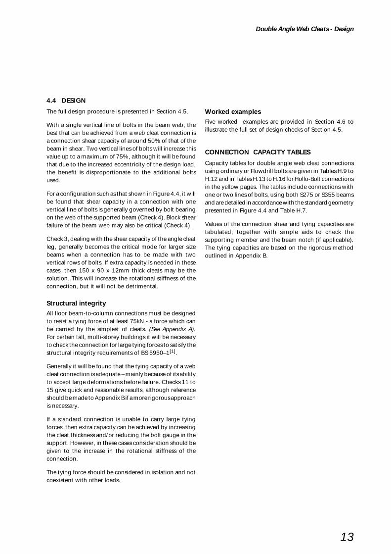
The full design procedure is presented in Section 4.5.
With a single vertical line of bolts in the beam web, thebest that can be achieved from a web cleat connection isa connection shear capacity of around 50% of that of thebeam in shear. Two vertical lines of bolts will increase thisvalue up to a maximum of 75%, although it will be foundthat due to the increased eccentricity of the design load,the benefit is disproportionate to the additional boltsused.
For a configuration such as that shown in Figure 4.4, it willbe found that shear capacity in a connection with onevertical line of bolts is generally governed by bolt bearingon the web of the supported beam (Check 4). Block shearfailure of the beam web may also be critical (Check 4).
Check 3, dealing with the shear capacity of the angle cleatleg, generally becomes the critical mode for larger sizebeams when a connection has to be made with twovertical rows of bolts. If extra capacity is needed in thesecases, then 150 x 90 x 12mm thick cleats may be thesolution. This will increase the rotational stiffness of theconnection, but it will not be detrimental.
Structural integrityAll floor beam-to-column connections must be designedto resist a tying force of at least 75kN - a force which canbe carried by the simplest of cleats. (See Appendix A).For certain tall, multi-storey buildings it will be necessaryto check the connection for large tying forces to satisfy thestructural integrity requirements of BS 5950–1[1].
Generally it will be found that the tying capacity of a webcleat connection is adequate – mainly because of its abilityto accept large deformations before failure. Checks 11 to15 give quick and reasonable results, although referenceshould be made to Appendix B if a more rigorous approachis necessary.
If a standard connection is unable to carry large tyingforces, then extra capacity can be achieved by increasingthe cleat thickness and/or reducing the bolt gauge in thesupport. However, in these cases consideration should begiven to the increase in the rotational stiffness of theconnection.
The tying force should be considered in isolation and notcoexistent with other loads.
Double Angle Web Cleats - Design
Worked examplesFive worked examples are provided in Section 4.6 toillustrate the full set of design checks of Section 4.5.
CONNECTION CAPACITY TABLES
Capacity tables for double angle web cleat connectionsusing ordinary or Flowdrill bolts are given in Tables H.9 toH.12 and in Tables H.13 to H.16 for Hollo-Bolt connectionsin the yellow pages. The tables include connections withone or two lines of bolts, using both S275 or S355 beamsand are detailed in accordance with the standard geometrypresented in Figure 4.4 and Table H.7.
Values of the connection shear and tying capacities aretabulated, together with simple aids to check thesupporting member and the beam notch (if applicable).The tying capacities are based on the rigorous methodoutlined in Appendix B.
14
Double Angle Web Cleats - Design Procedures
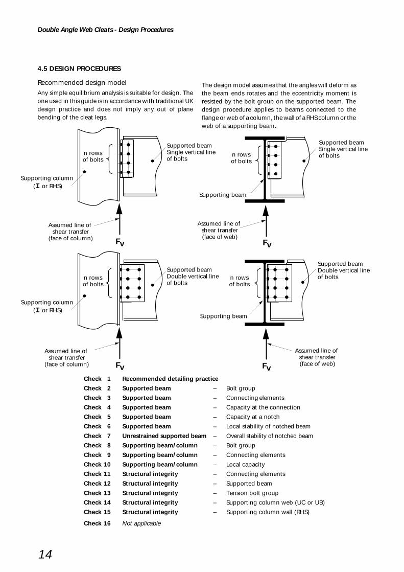
4.5 DESIGN PROCEDURES
Recommended design modelAny simple equilibrium analysis is suitable for design. Theone used in this guide is in accordance with traditional UKdesign practice and does not imply any out of planebending of the cleat legs.
Check 1 Recommended detailing practice
Check 2 Supported beam – Bolt group
Check 3 Supported beam – Connecting elements
Check 4 Supported beam – Capacity at the connection
Check 5 Supported beam – Capacity at a notch
Check 6 Supported beam – Local stability of notched beam
Check 7 Unrestrained supported beam – Overall stability of notched beam
Check 8 Supporting beam/column – Bolt group
Check 9 Supporting beam/column – Connecting elements
Check 10 Supporting beam/column – Local capacity
Check 11 Structural integrity – Connecting elements
Check 12 Structural integrity – Supported beam
Check 13 Structural integrity – Tension bolt group
Check 14 Structural integrity – Supporting column web (UC or UB)
Check 15 Structural integrity – Supporting column wall (RHS)
Check 16 Not applicable
The design model assumes that the angles will deform asthe beam ends rotates and the eccentricity moment isresisted by the bolt group on the supported beam. Thedesign procedure applies to beams connected to theflange or web of a column, the wall of a RHS column or theweb of a supporting beam.
Supporting column (I or RHS)
Supported beamSingle vertical line of bolts
Assumed line of shear transfer
(face of column)
n rowsof bolts
n rowsof bolts
Supported beamSingle vertical line of bolts
Supporting beam
n rowsof bolts
n rowsof bolts
Assumed line of shear transfer(face of web)
Supporting column (I or RHS)
Supported beamDouble vertical line of bolts
Supported beamDouble vertical line of bolts
Supporting beam
Assumed line of shear transfer
(face of column)
Assumed line of shear transfer(face of web)
Fv
FvFv
Fv
15
Double Angle Web Cleats - Design Procedures
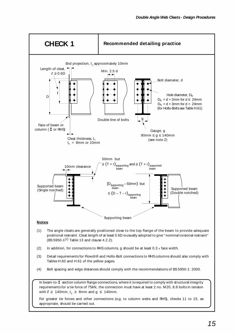
Notes
(1) The angle cleats are generally positioned close to the top flange of the beam to provide adequatepositional restraint. Cleat length of at least 0.6D is usually adopted to give “nominal torsional restraint”(BS 5950-1[1] Table 13 and clause 4.2.2).
(2) In addition, for connections to RHS columns, g should be at least 0.3 x face width.
(3) Detail requirements for Flowdrill and Hollo-Bolt connections to RHS columns should also comply withTables H.60 and H.61 of the yellow pages.
(4) Bolt spacing and edge distances should comply with the recommendations of BS 5950-1: 2000.
Hole diameter, DhDh = d + 2mm for d ≤ 24mmDh = d + 3mm for d > 24mm(for Hollo-Bolts see Table H.61)
Gauge, g90mm ≤ g ≤ 140mm
(see note 2)
Length of cleat, l ≥ 0.6D
CHECK 1 Recommended detailing practice
End projection, t approximately 10mm1
D
Face of beam or column ( I or RHS)
Bolt diameter, d
g
l
Min. 2.5 d
Double line of bolts
Cleat thickness, tt = 8mm or 10mm
c
c
(Dsupporting – 50mm) but
beam
≤ (D – T – r)supporting
beam
50mm but≥ (T + r)supporting and ≥ (T + r)supported
beam beam
10mm clearance
Supported beam(Single notched) Supported beam
(Double notched)
Supporting beam
In beam-to-I section column flange connections, where it is required to comply with structural integrityrequirements for a tie force of 75kN, the connection must have at least 2 no. M20, 8.8 bolts in tensionwith l ≥ 140mm, tc ≥ 8mm and g ≤ 140mm.
For greater tie forces and other connections (e.g. to column webs and RHS), checks 11 to 15, asappropriate, should be carried out.

16
Double Angle Web Cleats - Design Procedures
Shear capacity of bolt group connecting cleats to web of supported beam(taking account of eccentricity ‘a’ for single line of bolts and (a + x) for double line of bolts.)
Basic requirement:
Fs ≤ 2Ps
Fs = resultant force on outermost bolt due to direct shear and moment
For single line of bolts
Fs = (Fsv2 + Fsm
2 )1/2
FvFsv = vertical force on the bolt = –––due to direct shear n
Fv aFsm = force on the outermost = ––––bolt due to moment Zbg
n(n+1)pZbg = elastic section modulus = –––––––
of bolt group 6
For double line of bolts
Fs = ((Fsv + Fsmv)2 + Fsmh
2 )1/2
vertical force on the bolt FvFsv = = –––due to direct shear 2n
vertical force on the outermost M xFsmv = = –––
bolt due to moment Ibg
M yFsmh = horizontal force on the outermost = ––––
bolt due to moment Ibg
M = Fv (a + x)
Ibg = Σ s2
where:
p = bolt pitch
s = distance from centre ofbolt group to each bolt
smax = distance from centre ofbolt group to furthest bolt
2Ps = shear capacity of a singlebolt in double shear
= 2 ps As
ps = shear strength of a bolt
As = shear area of a bolt
Ibg = inertia of bolt group
CHECK 2 Supported beam – Bolt group
Check these bolts in shear under eccentric load
p
pp
aAssumed line ofshear transfer
n rowsof bolts
Fs
p
pp
aAssumed line ofshear transfer
FsFs
s
max
(a + x)
centre of bolt group
y
xI or RHS
Single Line of bolts Double Line of bolts
s
Assumed line ofshear transfer
Fv FvFv
17
Double Angle Web Cleats - Design Procedures
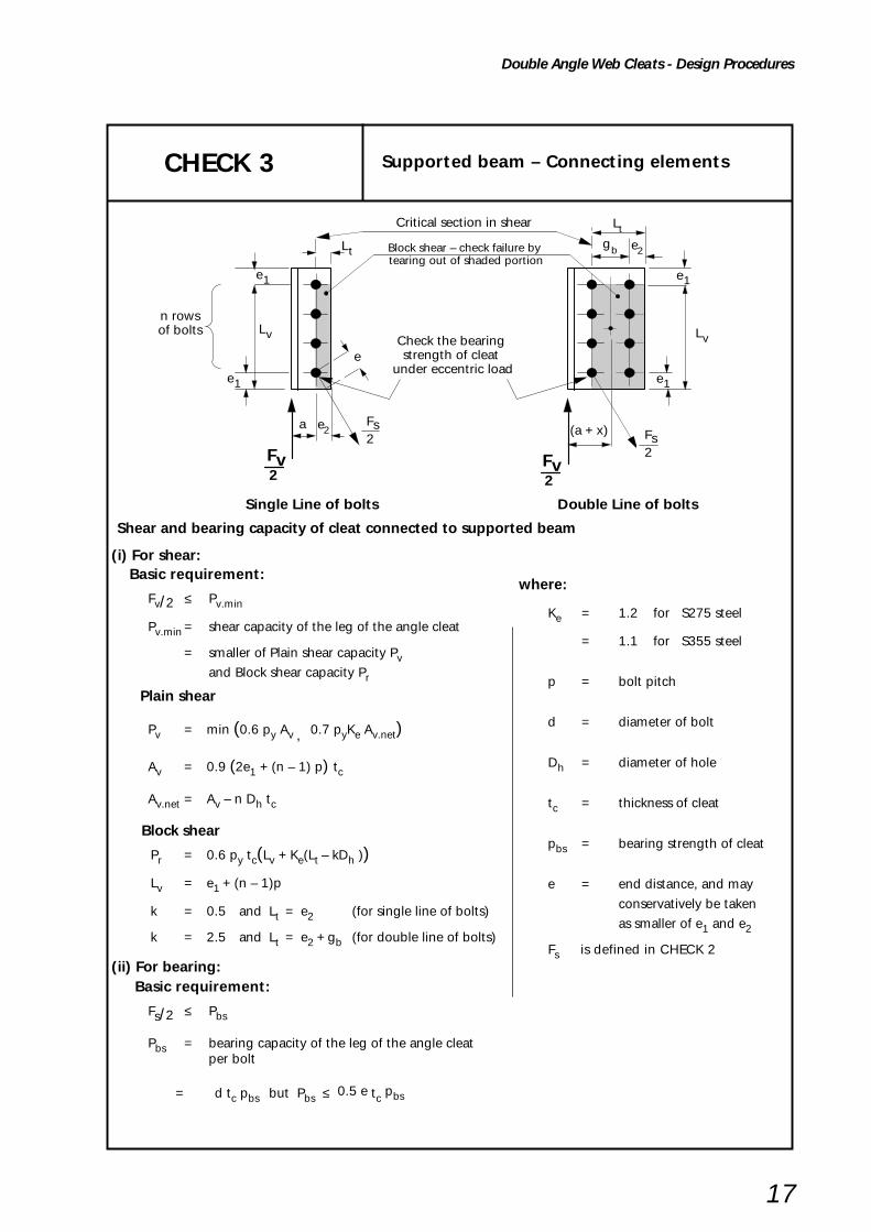
CHECK 3 Supported beam – Connecting elements
(i) For shear: Basic requirement:
Fv/2 ≤ Pv.min
Pv.min = shear capacity of the leg of the angle cleat
= smaller of Plain shear capacity Pvand Block shear capacity Pr
Plain shear
Pv = min (0.6 py Av , 0.7 pyKe Av.net)
Av = 0.9 (2e1 + (n – 1) p) tc
Av.net = Av – n Dh tc
Block shear
Pr = 0.6 py tc(Lv + Ke(Lt – kDh ))
Lv = e1 + (n – 1)p
k = 0.5 and Lt = e2 (for single line of bolts)
k = 2.5 and Lt = e2 + gb (for double line of bolts)
(ii) For bearing: Basic requirement:
Fs/2 ≤ Pbs
Pbs = bearing capacity of the leg of the angle cleatper bolt
= d tc pbs but Pbs ≤ 0.5 e tc pbs
where:
Ke = 1.2 for S275 steel
= 1.1 for S355 steel
p = bolt pitch
d = diameter of bolt
Dh = diameter of hole
tc = thickness of cleat
pbs = bearing strength of cleat
e = end distance, and may
conservatively be taken
as smaller of e1 and e2
Fs is defined in CHECK 2
Shear and bearing capacity of cleat connected to supported beam
Check the bearing strength of cleat
under eccentric load
a
n rowsof bolts
Single Line of bolts Double Line of bolts
e1 e1
2Fs
Block shear – check failure by tearing out of shaded portion
e2
e
Critical section in shear
(a + x)
e2gb
e1 e1
Lv Lv
2Fv
2Fv
Lt
2Fs
Lt

18
Double Angle Web Cleats - Design Procedures
CHECK 4 Supported beam – Capacity at the connection
(i) For shear:
Basic requirement:
Fv ≤ Pv.min
Pv.min = shear capacity of the beamat the connection
= smaller of:Plain shear capacity Pv andBlock shear capacity Pr
Plain shear
Pv = min (0.6 py Av , 0.7 pyKe Av.net)
Av = (et + (n – 1) p + eb) tw(for un-notched & Single notched beam)
Av = 0.9(et + (n – 1) p + eb) tw(for double notched beam)
Av.net = Av – n Dh tw
Shear, bending and bearing capacity of the supported beam:
Block shear (applicable to notched beams only)
Pr = 0.6 py tw(Lv + Ke(Lt – kDh ))
Lv = et + (n – 1)p
k = 0.5 and Lt = e3 (for single line of bolts)
k = 2.5 and Lt = e3 + gb (for double line of bolts)
where:Ke = 1.2 for S275 steel
= 1.1 for S355 steel
p = boIt pitch
Dh = diameter of hole
tw = thickness of supported beam web
Critical section in plain shear
Block shear failuretearing out of shaded portion
e t e t e t
eb ebeb
e t e t
eb eb
Critical section in plain shear
e3
n rowsof bolts
e3 gb
e3 e3
e3 b
Block shear failuretearing out of shaded portion
n rowsof bolts
e t
eb
e3 gbgt1 t1 t1
t1 t1 t1
Fv FvFv
Fv FvFv
Shear failure
Lt
Lv
Tension failure
Lt
Shear failure
Tension failure
Lt
Lt
Tension failure
Shear failure
Shear failure
Tension failure
Lv
19
Double Angle Web Cleats - Design Procedures
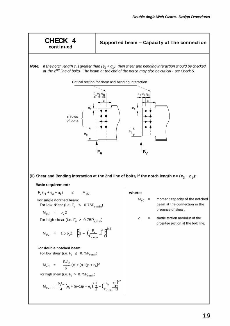
CHECK 4 Supported beam – Capacity at the connectioncontinued
(ii) Shear and Bending interaction at the 2nd line of bolts, if the notch length c > (e3 + gb):
Basic requirement:
Fv (t1 + e3 + gb) ≤ McC
For single notched beam: For low shear (i.e. Fv ≤ 0.75Pv.min)
McC = py Z
For high shear (i.e. Fv > 0.75Pv.min)
Fv2
1/2
McC = 1.5 pyZ 1 – ( –––– ) Pv.min
.....
For double notched beam: For low shear (i.e. Fv ≤ 0.75Pv.min)
pytw McC = ____ (et + (n-1)p + eb)2
6
For high shear (i.e. Fv > 0.75Pv.min)
pytw 2 Fv 2 1/2
McC = ____ (et + (n–1)p + eb) 1 – (____ ) 4 Pv.min .....
Note: If the notch length c is greater than (e3 + gb), then shear and bending interaction should be checkedat the 2nd line of bolts. The beam at the end of the notch may also be critical - see Check 5.
e t
eb
Critical section for shear and bending interaction
e3 b
e t
eb
e3 gbgt1 t1
n rowsof bolts
Fv Fv
cc c
where:
McC = moment capacity of the notched
beam at the connection in the
presence of shear.
Z = elastic section modulus of the
gross tee section at the bolt line.

20
Double Angle Web Cleats - Design Procedures
CHECK 4 Supported beam – Capacity at the connectioncontinued
pn rowsof bolts
Fs
e
e3
Check bolt group in bearing under
eccentric load
Fs
a
p
p
p
p
p
e
e3
(a + x)
Fv
Fv
(iii) For bearing:
Basic requirement:
Fs ≤ Pbs
Fs = resultant force as defined in CHECK 2.
Pbs = bearing capacity of the beam web per bolt
= d tw pbs but Pbs ≤ 0.5 e tw pbs
pbs = bearing strength of beam web
e = end distance, and may conservatively be taken as e3

21
Double Angle Web Cleats - Design Procedures
CHECK 5 Supported beam – Capacity at a notch
Basic requirement:
(a) For single bolt line or for double bolt lines, if xN ≥ 2d:
Fv (t1 + c) ≤ McN
McN for Single notched beam:
For low shear (i.e. Fv ≤ 0.75PvN)
McN = pyZN
For high shear (i.e. Fv > 0.75PvN)
Fv 1/2
McN = 1.5pyZN 1 – ( ___ )2
PvN .....
McN for Double notched beam:
For low shear (i.e. Fv ≤ 0.75PvN)
pytwMcN = ____ (et + (n–1)p + eb)
2
6
For high shear (i.e. Fv > 0.75PvN)
pytw 2 Fv 2 1/2
McN = ____ (et + (n–1)p + eb) 1 – (____ ) 4 PvN .....
(b) For double bolt lines, if xN < 2d:
max ( Fv(t1+c), Fv(t1+e3+gb)) ≤ McN
McN = McC from CHECK 4
Shear and bending interaction at the notch:
t c1
Critical sections
t c1 t c1
e t
eb
n rowsof bolts
e t
eb
e t
eb
to notch or beam flange
t c1
e t
eb
Fv Fv Fv Fv x N x N
where:McN = moment capacity of the beam at the
notch in the presence of shear
PvN = shear capacity at the notch
= 0.6 py AvN
AvN = (et + (n – 1) p + eb)tw
(for single notched beam)
= 0.9(et + (n – 1) p + eb)tw
(for double notch beam)
t1 = end projection
tw = thickness of supported beam web
c = length of notch
ZN = elastic section modulus of the gross tee
section at the notch
xN = +ve
e3 , gb as per CHECK 4

22
Double Angle Web Cleats - Design Procedures
When the beam is restrained against lateral torsional buckling, no account need be taken of notch stability provided the following conditions are met:
For one flange notched [14],[l5]
Basic requirement:
dc1 ≤ D/2 and:
c ≤ D for D/tw ≤ 54.3 (S275 steel)
160000Dc ≤ –––––––– for D/tw > 54.3 (S275 steel)
(D/tw)3
c ≤ D for D/tw ≤ 48.0 (S355 steel)
110000Dc ≤ –––––––– for D/tw > 48.0 (S355 steel)
(D/tw)3
For both flanges notched [15]
Basic requirement:
Max (dc1 , dc2) ≤ D/5 and:
c ≤ D for D/tw ≤ 54.3 (S275 steel)
160000Dc ≤ –––––––– for D/tw > 54.3 (S275 steel)
(D/tw)3
c ≤ D for D/tw ≤ 48.0 (S355 steel)
110000Dc ≤ –––––––– for D/tw > 48.0 (S355 steel)
(D/tw)3
where:
tw = thickness of supported beam web
Where the notch length c exceeds these limits, either suitable stiffening should be provided or the notch
should be checked to references 14, 15 and 16.
CHECK 6 Supported beam - Local stability of notched beam
D
c
D
c
c
dc1dc1
dc2

23
Double Angle Web Cleats - Design Procedures
CHECK 7 Unrestrained supported beamOverall stability of notched beam
When a notched beam is unrestrained against lateral torsional buckling, the overallstability of the beam should be checked.
Notes:
(1) This check is only applicable for beams with one flange notched. Guidance on double-notched
beams is given in Section 5.12 of Reference 17.
(2) If the notch length c and/or notch depth dc1 are different at each end, then the larger values for
c and dc1 should be used.
(3) Beams should be checked for lateral torsional buckling to BS 5950-1[1], clause 4.3 with a
modified effective length (LE) which takes account of notches.
(4) The solution below gives the modified effective length (LE) based on references 18, 19 and 20.
It is only valid for c /Lb < 0.15 and dc1/D < 0.2 (beams with notches outside these limits should
be checked as tee sections, or stiffened).
2c 1/2
LE = Lb 1 + –– (K2 + 2K) Lb
K = Ko/λb
u v Lbλb = –––––– ry
where: x, u, v and ry are for the un-notched I beam section and are defined in BS 5950-1
Conservatively, u = 0.9 and v = 1.0
for λb < 30 Ko = 1.1 go x but ≤ 1.1 Kmax
for λb ≥ 30 Ko = go x but ≤ Kmax
go and Kmax are tabulated below:
c
D
b
c
L
dc1dc1
c Kmax ––
go UB UC Lb
section section
≤ .025 5.56 260 70
.050 5.88 280 80
.075 6.19 290 90
.100 6.50 300 95
.125 6.81 305 95
.150 7.13 315 100

24
Double Angle Web Cleats - Design Procedures
Shear capacity of bolt group connecting cleats to supporting beam or column
Basic requirement:
Fv ≤ Σ Ps
Ps = shear capacity of single bolt
= ps As*
but for the top pair of bolts, Ps is the smaller of:
ps As* or 0.5 kbs e1 tc pbs
Check these bolts in shearunder concentric load
Check these bolts in shearunder concentric load
Supporting beam
Supporting columnI or RHS
e1 e1
CHECK 8 Supporting beam/column - Bolt group
where:
ps = shear strength of a bolt
As = shear area of a bolt
tc = thickness of cleat
pbs = bearing strength of cleat
e1 = end distance
kbs = 1.0 for standard clearance holes,
Flowdrill and Hollo-Bolts
= 0.7 for short slotted holes
* For Hollo-Bolts ps As should be taken as the shear capacity given in Table H.56 of the yellow pages

25
Double Angle Web Cleats - Design Procedures
CHECK 9 Supporting beam/column- Connecting elements
(Legs of cleats adjacent to supporting beam or column)
(i) For shear:
Basic requirement:
Fv/2 ≤ Pv.min
Pv.min = shear capacity of the leg of the angle cleat
= smaller of Plain shear capacity Pvand Block shear capacity Pr
Plain shear
Pv = min (0.6 py Av , 0.7 pyKe Av.net)
Av = 0.9 (2e1 + (n – 1) p) tc Av.net = Av – n Dh tc
Block shear
Pr = 0.6 py tc(Lv + Ke(Lt – kDh ))
Lv = e1 + (n – 1)p
(ii) For bearing:
Basic requirement:
Fv/2 ≤ Σ Pbs
Σ Pbs = bearing capacity of the leg of the single
angle cleat (ie. for 'n' bolts)
Pbs = bearing capacity of the leg of the angle cleat per bolt
= kbsd tc pbs
but for the top bolt, Pbs is the smaller of:
kbsd tc pbs or 0.5 kbs e1 tc
pbs
where:
p = bolt pitch
d = diameter of bolt *
Dh = diameter of hole *
tc = thickness of cleat
pbs = bearing strength of cleat
e1 = end distance
k = 0.5 and Lt = e2(for single line of bolts in
the outstanding leg)
Ke = 1.2 for S275 steel
= 1.1 for S355 steel
kbs = 1.0 for standard clearence holes,
Flowdrill and Hollo-Bolts
= 0.7 for short slotted holes
* For Hollo-Bolts d is the nominal boltdiameter but Dh is the hole diameter in thecleat as given in Table H.61 of the yellowpages.
Shear and bearing capacity of cleats connected to supporting beam or column
Critical section in shear and bearing
n rowsof bolts
Block shear – check failure by tearing out of shaded portion
e1
e1
e1
e2
Lt
Lv
2Fv
2Fv
2Fv
2Fv
e2

26
Double Angle Web Cleats - Design Procedures
CHECK 10 Supporting beam/column - Local capacity(with one supported beam)
(i) For shear:
Basic requirement:
Fv/2 ≤ Pv
Pv = Iocal shear capacity of supporting beam webor I column web or RHS column wall
Pv = min (0.6 py Av , 0.7 pyKe Av.net)
Av = (et + (n – 1) p + eb) tw
Av.net = Av – n Dh tw
(ii) For bearing:
Basic requirement:
Fv––– ≤ Pbs2 n
Pbs = bearing capacity of supporting beamor column per bolt
= kbsd tw pbs
pbs = bearing strength of supporting beam or column
where:et = smaller of et1 and 5d
eb = smallest of eb1, g/2 and 5d(for supporting beam)
= smaller of g/2 and 5d(for supporting column)
p = bolt pitch
d = diameter of bolt *
Dh = diameter of hole *
tw = thickness of supportingbeam web or column webor RHS wall
kbs = 1.0 for standard clearence holes,
Flowdrill and Hollo-Bolts
Ke = 1.2 for S275 steel
1.1 for S355 steel
* For Hollo-Bolts d is the nominal boltdiameter but Dh is the hole diameter in thecleat as given in Table H.61 of the yellow pages.
For Flowdrill the diameter of the hole is thebolt diameter.
Note: The above check (i) is for local shear only; the effects of any global shear forces must also be considered.
If the beam is connected to a rolled column flange, and the thickness of the column flange is less thanthe thickness of the cleat then the bearing capacity of the flange should also be checked.
et1
I Column RHS Column
web thickness wt
Supporting Beam
web thickness wt
Top of column web or RHS wall
Critical sectionsCritical sections
eb1
g
et1
g g
Supporting Column
n rowsof bolts
n rowsof bolts
wall thickness wt
2Fv
2Fv
2Fv
2Fv
2Fv
2Fv
Fv Fv
Local shear and bearing capacity of supporting beam web or column web or RHS wallfor one supported beam

27
Double Angle Web Cleats - Design Procedures
CHECK 10 Supporting beam/column - Local capacity(continued) (with two supported beams)
Notched toclear bolts
wt
Notched toclear bolts
e t1
Supporting beam Critical sections
eb2
Critical sections
Supporting I ColumnSupporting Beam
Top of column web
1n rowsof bolts
1n rowsof bolts
2n rowsof bolts
2 n rowsof bolts
e t1
g g
Fv1Fv2 Fv1Fv2
F + Fv2v12
F + Fv2v12
F + Fv2v12
F + Fv2v12
(i) For shear:
Basic requirement:
Fv1A Fv2––– + ––– ≤ Pv 2 2
n2Fv1A = Fv1––– n1
Pv = Iocal shear capacity of supporting
beam web or column web
Pv = min (0.6 py Av , 0.7 pyKe Av.net)
Av = (et + (n2 – 1) p + eb) tw
Av.net = Av – n2 Dh tw
(ii) For bearing:
Basic requirement:
Fv1 Fv2––– + ––– ≤ Pbs2n1 2n2
Pbs = bearing capacity of supporting beamor column per bolt
= d tw pbs
pbs = bearing strength of supporting beamor column
where:et = smaller of et1 and 5d
eb = smallest of eb2, g/2, p and 5d(for supporting beam)
= smallest of g/2, p and 5d(for supporting column)
p = bolt pitch
d = diameter of bolt
Dh = diameter of hole
tw = thickness of supportingbeam web or column web
Ke = 1.2 for S275 steel
= 1.1 for S355 steel
Local shear and bearing capacity of supporting beam web or column web for two supported beams
Note: The above check (i) is for local shear only; the effects of any global shear forces must also be considered.

28
Double Angle Web Cleats - Design Procedures
CHECK 11 Structural integrity - connecting elements
Note: This check is only needed if it is necessary to comply with structural integrity requirements
Structural integrity – tension capacity of double angle web cleats
n rowsof bolts
e
e g
1
e1
p
p
p
Critical sections
Tie force
2
where: Le = effective net length
= 2ee + (n – 1) pe – n Dh
ee = e1 but ≤ e2
pe = p but ≤ 2e2
p = bolt pitch
Dh = diameter of hole *
tc = thickness of cleat
* For Hollo-Bolts Dh is the hole diameter in thecleat as given in Table H.61 of the yellow pages.
Basic requirement:
Tie force ≤ Tying capacity of double angle web cleats
Tying capacity of double angle web cleats
= 0.6 Le tc py for S 275 steel (see Appendix B)
= 0.5 Le tc py for S 355 steel (see Appendix B)
Limitations:
g ≤ 140mm
tc ≥ 8mm
Note: Appendix B, gives a rigorous approach for calculating the tension capacity of double angle cleats. The capacity tables on the yellow pages are based on the rigorous approach and not the simplified
approach given here.

29
Double Angle Web Cleats - Design Procedures
CHECK 12 Structural integrity - supported beam
Note: This check is only needed if it is necessary to comply with structural integrity requirements
Structural integrity – tension and bearing capacity of beam web
(i) For tension Basic requirement:
Tie force ≤ Net tension capacity of beam web
Net tension capacity of beam web
= Le tw py
(ii) For bearing Basic requirement:
Tie force ≤ Bearing capacity of beam web
Bearing capacity of beam web
= 1.5n d t w pbs but
≤ 0.5ne3tw pbs
for single line of bolts
= 3n d t w pbs but
≤ n(1.5d t w pbs + 0.5 e3 twpbs )for double line of bolts
where:
Le = effective net length
= 2ee + (n – 1)pe – nDh
ee = e3 but ≤ et for single line of bolts
ee = e3 + gb – Dh but ≤ et for double line of bolts
pe = p but ≤ 2e3 for single line of bolts
pe = p but ≤ 2(e3 + gb – Dh) for double line of bolts
tw = beam web thickness
p = bolt pitch
Dh = diameter of hole
d = diameter of bolt
pbs = bearing strength of beam web(BS 5950–1, Table 32)
n rowsof bolts
et
p
p
p
n rowsof bolts
et
p
p
p
et
Tie force Tie force
Tie force Tie force
et
gb
bg
e3 e3
e3e3

30
Double Angle Web Cleats - Design Procedures
CHECK 13 Structural integrity – Tension bolt group
Tension bolt
groupTie force
Basic requirement:
Tie force ≤ Tension capacity oftension bolt group
Tension capacity of= 2n At ptr *tension bolt group
* See Note (3) for Flowdrill or Hollo-Bolts
where:
n = number of rows of bolts
At = tensile stress area of a bolt
ptr = reduced tension strength of abolt in presence of extreme prying
= 300N/mm2 for grade 8.8 bolts(see Appendix D)
Notes:
(1) The reduced tension strength, (ptr) is only used when double angle web cleat design for structural
integrity is based on Appendix B or CHECK 11.
(2) Where a beam is attached to one side of a column web without a beam on the opposite side, or to
RHS column, the bolt tensions have to be resisted by local bending of the web or RHS wall. UC webs
can resist 75kN but need to be checked if the tying force is higher. UB webs need to be checked for 75kN
and higher tying forces. CHECK 14 proposes a design model which could be used for this purpose.
CHECK 15 proposes a design model for checking the wall of RHS column.
(3) For Flowdrill or Hollo-Bolt connections the value At ptr is replaced by the Structural integrity Tensile
Capacity (Psi) taken from Tables H.55b and H.56 respectively, in the yellow pages.
Note: This check is only needed if it is necessary to comply with structural integrity requirements
Structural integrity – tension capacity of bolts in presence of extreme prying

31
Double Angle Web Cleats - Design Procedures
Basic requirement:
Tie force ≤ Tying capacity of column web
Tying capacity 8 Mu= ––––– (η
1 + 1.5(1 – β1)0.5 (1 – γ1)0.5) *of column web 1 – β 1
Mu = moment capacity of column
web per unit length
pu tw2
= –––––– 4
pu
= design tensile strength of the column
= Us /1.25 (see inset box)
* Factor 1.5 in the equation includes an allowance forthe axial compression in the column.
CHECK 14 Structural integrity – Supporting column web (UC or UB)
Note: This check is only needed if it is necessary to comply with structural integrity requirements
Structural integrity – Tying capacity of rolled column web, in the presence of axial compression inthe column
where:
(n-1) p – n
Dh 2η1 = ––––––––––––––
dc gβ1 = –––
dc
Dhγ1 = –––
dc
d c = depth of column between fillets
tw = thickness of column web
g = gauge (cross centres)
Dh = diameter of hole
Note: The check is required for either single-sided connections to the rolled column webor unequally loaded double-sided connections to the rolled column web.
g
t w
Tie Force
Angle cleatsconnecting to column web
d c
(n-1)p
bolt holes deducted
yield lines
p
Design tensile strength
pu = Us /1.25
S275 328 N/mm2
S355 392 N/mm2
Values of Us taken from BS EN 10025: 1993[21]

CHECK 15 Structural integrity –Supporting column wall (RHS)
Tie Force
g
1.5t w
t w
B
Angle cleats connecting to RHS columnp (n-1)p
bolt holes deducted
yield lines
Note: This check is only needed if it is necessary to comply with structural integrity requirements
Structural integrity – Tying capacity of RHS wall, in the presence of axial compression in thecolumn
Basic requirement:
Tie force ≤ Tying capacity of RHS column wall
Tying capacity 8 Mu= ––––– (η
1 + 1.5(1 – β1)0.5 (1 – γ1)0.5) * RHS column wall 1 – β 1
Mu = moment capacity of RHS column
wall per unit length
pu tw2
= –––––– 4
pu = design tensile strength of the RHS column
= Us /1.25 (see inset box)
* Factor 1.5 in the equation includes an allowance forthe axial compression in the column.
where:
(n-1) p – n
Dh 2η1 = –––––––––––––––
(B – 3tw) g
β1 = –––––––– (B – 3tw)
Dhγ1 = ––––––––
(B – 3tw)
B = overall width of RHS column wallto which the connection is made
tw = thickness of RHS column
Dh = diameter of hole in RHS
= bolt diameterfor Flowdrill
= hole diameter (in RHS) givenin Table H.61 of yellow pagesfor Hollo-Bolt
g = gauge (cross centres)
n = number of rows of bolts
p = bolt pitch
32
Double Angle Web Cleats - Design Procedures
Design tensile strength
pu = Us /1.25
S275 328 N/mm2
S355 392 N/mm2
Values of Us taken fromBS EN 10210 - 1:1994[3]
33
Double Angle Web Cleats - Worked Examples
4.6 WORKED EXAMPLES
The worked examples show design calculations for typicalstandard connections. Each example demonstrates firstthe use of the capacity tables (yellow pages) and then fullchecks according to the procedures in Section 4.5. The fullchecks will normally only need to be applied to non-standard connections but their application to standardconnections demonstrates the validity of the much simplerprocess when using standard details.
When calculations must be made for non-standardconnections, some design checks may be omitted whereit is obvious, from inspection of the detail, that a check is notcritical. In the case of Example 1, CHECK 3 and CHECK 9Block Shear calculation are not made since they are nevera critical factor for well proportioned angle cleats withbolts spaced at reasonable centres in the cleat length.However, if a connection design were made using along cleat with bolts concentrated at one end of thecleat, it is possible that Block Shear failure could occurbefore Plain Shear failure and then the Block shearchecks should be made.
CHECK 7, dealing with overall stability of an unrestrainedbeam, should be undertaken by the member designertaking account of any notching required at the ends of thesupported beam in order to facilitate the use of a simpleconnection.
CHECKS 11 to 15 all deal with structural integrity in thepresence of an axial tie force required to be developed insome members to ensure the steel frame is sufficientlyrobust, or in the case of some multi-storey buildings, tolocalise accidental damage. When tying capacity is notrequired these checks may be omitted.
Example 1
Example 1 covers design checks for a two sided beam-to-beam connection.
Example 2
Example 2 demonstrates the additional design checksrequired when a beam-to-column connection must bedesigned to resist tying forces.
Example 3
Example 3 is a beam connection to an RHS column usingnormal grade 8.8 bolts in Flowdrill threaded holes toconnect double angle web cleats to the column wall. Thebeam sizes, vertical reactions and tie forces are the sameas in Examples 1 and 2, so only checks which are differentto the those shown previously are illustrated.
It should be noted that tie forces are ignored in checks forvertical reactions and vertical reactions are ignored inchecks for tie forces.
Example 4
Example 4 covers the same beam connections to an RHScolumn as in Example 3 but uses Hollo-Bolts to connectdouble angle web cleats to the column wall.
Example 5
Example 5 demonstrates the stability CHECK 7 for alaterally unrestrained beam with a single notch at eachend. Although this example is presented here, it is equallyapplicable to flexible end plates and fin plates.

Double Angle Web Cleats - Worked Example 1
34
Title Example 1 - Double Angle Cleats - Beam to Beam Sheet
BCSA
CALCULATIONSHEET
Calcs by
Title
Client
Checked by Date
Job NoJoints in Steel Construction - Simple Connections
Example 1 - Double Angle Cleats - Beam to Beam
SCI/BCSA Connections Group
RS AM May 2002
DESIGN EXAMPLE 1
Check the following beam to beam connection for the design forces shown.
Yellow pages used for initial selection of Angle cleats.
See Figure 4.4
Design Information:
Bolts: M20 8.8
Material: All S275
1 of 18
REF.
50 50
50
50 Notch
40
70
70
70
70
7040
40
10 Projection
Flange chamferedto clear bolts
610 x 229 x 140 UBGrade S275
300kN 465kN
N=120
406 x 178 x 74 UBGrade S275
533 x 210 x 92 UBGrade S275
50
2 - 150 x 90 x 10angle cleats (Type CB4)Grade S275
2 - 90 x 90 x 10angle cleats (Type CA6)Grade S275
Yellow pagesTable H.2
Sheet

Double Angle Web Cleats - Worked Example 1
35
Title Example 1 - Double Angle Cleats - Beam to Beam Sheet
CONNECTION DESIGN USING CAPACITY TABLES FROM YELLOW PAGES
406 x 178 x 74 UB Grade S275 533 x 210 x 92 UB Grade S275
Cleat type CB4 Grade S275 Cleat type CA6 Grade S275
Bolts M20 8.8 Bolts M20 8.8
From capacity table H.10 From capacity table H.9 Yellow pagesin Yellow pages in Yellow pages Tables
H.10 & H.9
Connection shear capacity Connection shear capacity= 404kN > 300kN = 475kN > 465kN ∴ O.K.
Maximum notch length Maximum notch length(c + t1) = 221mm > 120mm (c + t1) = 346mm > 120mm ∴ O.K.
Web thickness of supporting beam = 13.1mm Table H.64
Minimum support thickness = 5.5 + 4.3 = 9.8mm < 13.1mm ∴ O.K.
Connection is adequate
610 x 229 x 140 UBGrade S275
300kN 465kN
406 x 178 x 74 UBGrade S275 533 x 210 x 92 UB
Grade S275
2 of 18
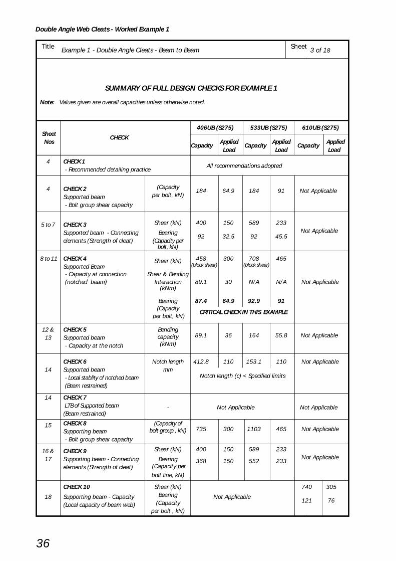
Double Angle Web Cleats - Worked Example 1
36
Title Example 1 - Double Angle Cleats - Beam to Beam Sheet
SUMMARY OF FULL DESIGN CHECKS FOR EXAMPLE 1
Note: Values given are overall capacities unless otherwise noted.
406UB (S275) 533UB (S275) 610UB (S275) Sheet
CHECK Nos
Capacity Applied
CapacityApplied
Capacity Applied
Load Load Load
4 CHECK 1 - Recommended detailing practice
All recommendations adopted
4 CHECK 2 (Capacity184 64.9 184 91 Not Applicable
Supported beam per bolt, kN)
- Bolt group shear capacity
5 to 7 CHECK 3 Shear (kN) 400 150 589 233
Supported beam - Connecting Bearing92 32.5 92 45.5
Not Applicable
elements (Strength of cleat) (Capacity perbolt, kN)
8 to 11 CHECK 4 458 300 708 465Supported Beam
Shear (kN) (block shear) (block shear)
- Capacity at connection Shear & Bending (notched beam) Interaction 89.1 30 N/A N/A Not Applicable
(kNm)
Bearing 87.4 64.9 92.9 91(Capacity CRITICAL CHECK IN THIS EXAMPLE
per bolt, kN)
12 & CHECK 5 Bending89.1 36 164 55.8
Not Applicable13 Supported beam capacity
- Capacity at the notch (kNm)
CHECK 6 Notch length 412.8 110 153.1 110 Not Applicable14 Supported beam mm
- Local stablity of notched beam Notch length (c) < Specified limits
(Beam restrained)
14 CHECK 7
LTB of Supported beam - Not Applicable Not Applicable(Beam restrained)
15 CHECK 8 (Capacity of735 300 1103 465 Not ApplicableSupporting beam bolt group , kN)
- Bolt group shear capacity
16 & CHECK 9 Shear (kN) 400 150 589 233
17 Supporting beam - Connecting Bearing 368 150 552 233 Not Applicable
elements (Strength of cleat) (Capacity perbolt line, kN)
CHECK 10 Shear (kN) 740 305
18 Supporting beam - Capacity Bearing Not Applicable121 76
(Local capacity of beam web) (Capacityper bolt , kN)
3 of 18
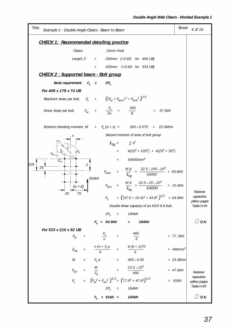
Double Angle Web Cleats - Worked Example 1
37
Title Example 1 - Double Angle Cleats - Beam to Beam Sheet
CHECK 1: Recommended detailing practice
Cleats: 10mm thick
Length, l = 290mm (>0.6D for 406 UB)
= 430mm (>0.6D for 533 UB)
CHECK 2 : Supported beam - Bolt group
Basic requirement: Fs ≤ 2Ps
For 406 x 178 x 74 UB
Resultant shear per bolt, Fs = ((Fsv + Fsmv ) 2 + Fsmh2 )1/2
Fv 300 Direct shear per bolt, Fsv = –––– = –––– = 37.5kN
2n 8
Eccentric bending moment, M = Fv (a + x) = 300 x 0.075 = 22.5kNm
Second moment of area of bolt group
I bg = ∑ s2
= 4(252 + 1052) + 4(252 + 352)
= 54000mm4
M y 22.5 x 105 x 103 Fsmh = ––– = –––––––––––––– = 43.8kN
I bg 54000
M x 22.5 x 25 x 103Fsmv = ––– = ––––––––––––– = 10.4kN
I bg 54000
Fs = ((37.5 + 10.4)2 + 43.82 )1/2 = 64.9kN
Double shear capacity of an M20 8.8 bolt,
2Ps = 184kN
Fs = 64.9kN < 184kN ∴ O.K.
For 533 x 210 x 92 UBFv 465
Fsv = ––– = ––– = 77. 5kNn 6
n (n + l) p 6 (6 + 1)70Zbg = ––––––––– = ––––––––– = 490mm3
6 6
M = Fv a = 465 x 0.05 = 23.3kNm
M 23.3 x 10³Fsm = –– = ––––––––– = 47.6kN
Zb 490
Fs = (Fsv2 + Fsm
2 )1/2= (77.52 + 47.62)1/2
= 91kN
2Ps = 184kN
Fs = 91kN < 184kN ∴ O.K.
Fastenercapacities
yellow pagesTable H.49
Fastenercapacities
yellow pagesTable H.49
4 of 18
smsmv
smh
svF
F
F
F
35105
(a + x)
75
300kN
y
x
25
sF

Double Angle Web Cleats - Worked Example 1
38
Title Example 1 - Double Angle Cleats - Beam to Beam Sheet
CHECK 3 : Supported Beam - Connecting Elements
Fv(i) Basic requirement for shear: Applied Shear –– < Pv.min 2
For 406 x 178 x 74 UBShear capacity of cleat leg, Pv.min is the smaller of Plain shear capacity Pvand Block shear capacity Pr
Plain shear Pv = min (0.6 py Av or 0.7 py Ke A v.net )Shear area, Av = 0.9(2e1 + (n - l)p ) tc
= 0.9(80 + 210) x 10
= 2610mm2
Net area, Av.net = Av – n Dh tc
= 2610 – (4 x 22 x 10) = 1730mm2
0.6 x 275 x 26100.6py Av = –––––––––––––– = 431kN
103
0.7 x 275 x 1.2 x17300.7pyKeAv.net = –––––––––––––––––– = 400kN
103
∴ Pv = 400kN
Block shear Pr = 0.6py tc ( Lv + Ke ( Lt – kDh ))Lv = e1 + (n – 1)p = 40 + 210 = 250mm
Lt = e2 + gb = 50 + 50 = 100mm
k = 2.5 (for double line of bolts)
Ke = 1.2 (for S275)
0.6 x 275 x 10 (250 + 1.2(100 – 2.5 x 22))∴ Pr = –––––––––––––––––––––––––––––––––––– 103
= 502kN
Pv.min = min (Pv , Pr )
= 400kN
Fv/2 = 150kN < 400kN ∴∴∴∴∴ O.K.
NOTE:
Block shear checks have been shown here, but they are never critical for well proportioned cleats.
However, if the bolt spacing is concentrated at one part of a cleat then these checks may be critical.
e 1
(n – 1)p= 210
= 40
2
e 1= 40
F v
e 2 = 50 gb = 50
5 of 18
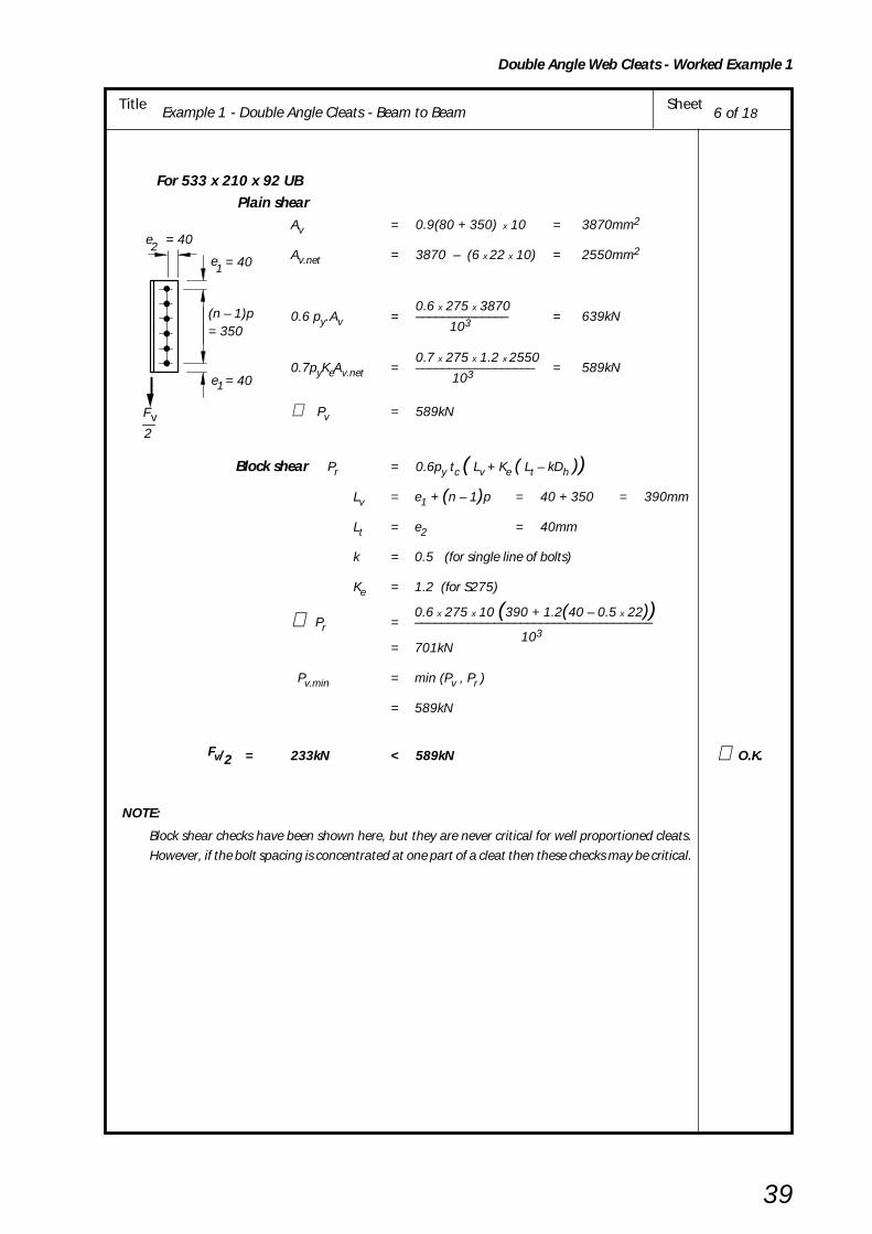
Double Angle Web Cleats - Worked Example 1
39
Title Example 1 - Double Angle Cleats - Beam to Beam Sheet
For 533 x 210 x 92 UB Plain shear
Av = 0.9(80 + 350) x 10 = 3870mm2
Av.net = 3870 – (6 x 22 x 10) = 2550mm2
0.6 x 275 x 38700.6 py.Av = –––––––––––––– = 639kN
103
0.7 x 275 x 1.2 x 25500.7pyKeAv.net = –––––––––––––––––– = 589kN
103
∴ Pv = 589kN
Block shear Pr = 0.6py tc ( Lv + Ke ( Lt – kDh ))Lv = e1 + (n – 1)p = 40 + 350 = 390mm
Lt = e2 = 40mm
k = 0.5 (for single line of bolts)
Ke = 1.2 (for S275)
0.6 x 275 x 10 (390 + 1.2(40 – 0.5 x 22))∴ Pr = –––––––––––––––––––––––––––––––––––– 103
= 701kN
Pv.min = min (Pv , Pr )
= 589kN
Fv/2 = 233kN < 589kN ∴ O.K.
NOTE:
Block shear checks have been shown here, but they are never critical for well proportioned cleats.
However, if the bolt spacing is concentrated at one part of a cleat then these checks may be critical.
= 40
= 40
= 350(n – 1)p
e1
1e
2
F v
= 402e
6 of 18
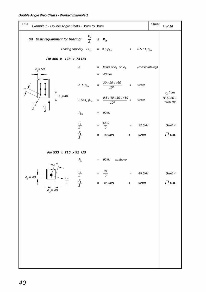
Double Angle Web Cleats - Worked Example 1
40
Title Example 1 - Double Angle Cleats - Beam to Beam Sheet
Fs(ii) Basic requirement for bearing: –– ≤ Pbs2
Bearing capacity, Pbs = d tc pbs ≤ 0.5 e tc pbs
For 406 x 178 x 74 UB
e = lesser of e1 or e2 (conservatively)
= 40mm
20 x 10 x 460d tc pbs = –––––––––––– = 92kN
103
0.5 x 40 x 10 x 4600.5e tc pbs = ––––––––––––––– = 92kN
103
Pbs = 92kN
Fs 64.9–– = –– = 32.5kN Sheet 42 2
Fs–– = 32.5kN < 92kN ∴∴∴∴∴ O.K.2
For 533 x 210 x 92 UB
Pbs = 92kN as above
Fs 91–– = ––– = 45.5kN Sheet 42 2
Fs–– = 45.5kN < 92kN ∴∴∴∴∴ O.K.2
2
1
s
e = 50
e
e = 40
F
2
F2
v
e
e = 40
F
2
s
2
1 e = 40
pbs from
BS 5950-1Table 32
7 of 18
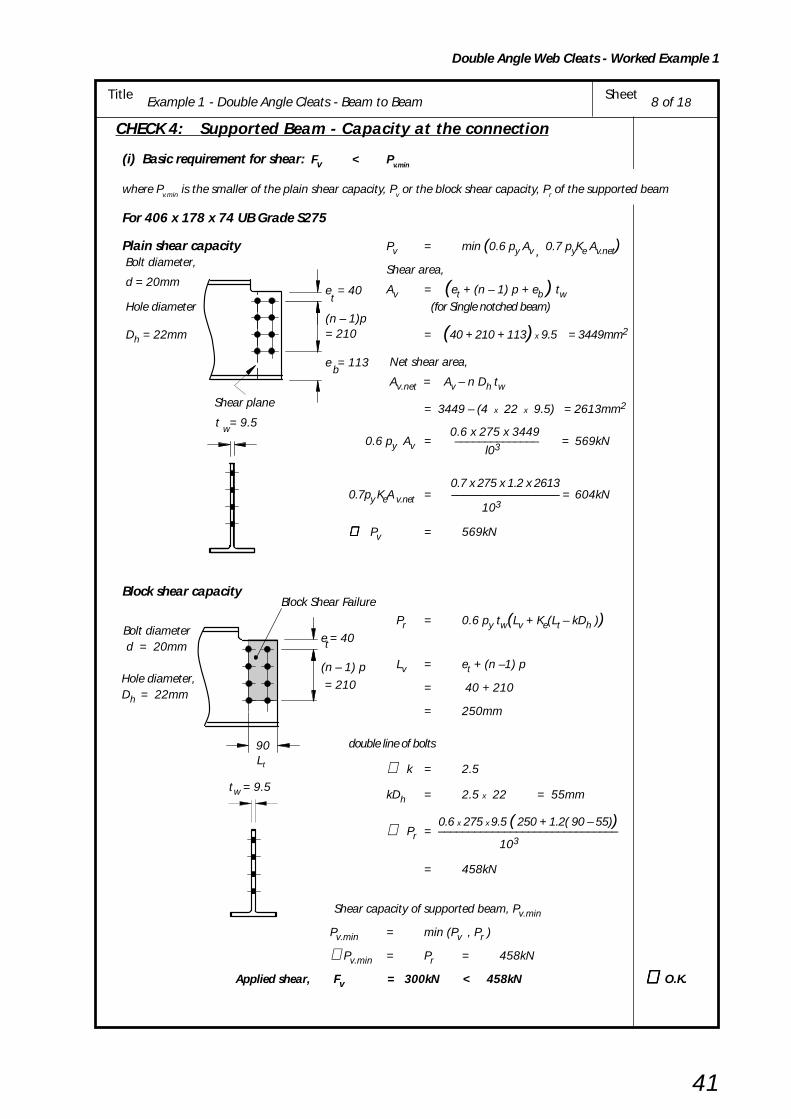
Double Angle Web Cleats - Worked Example 1
41
Title Example 1 - Double Angle Cleats - Beam to Beam Sheet
CHECK 4: Supported Beam - Capacity at the connection
(i) Basic requirement for shear: Fv < Pv.min
where Pv.min is the smaller of the plain shear capacity, Pv or the block shear capacity, Pr of the supported beam
For 406 x 178 x 74 UB Grade S275
Plain shear capacity Pv = min (0.6 py Av , 0.7 pyKe Av.net) Bolt diameter,
Shear area, d = 20mm
Av = (et + (n – 1) p + eb ) tw Hole diameter (for Single notched beam)
Dh = 22mm = (40 + 210 + 113) x 9.5 = 3449mm2
Net shear area,
Av.net = Av – n Dh tw
= 3449 – (4 x 22 x 9.5) = 2613mm2
0.6 x 275 x 3449 0.6 py Av = –––––––––––––– = 569kN
l03
0.7 x 275 x 1.2 x 26130.7py KeA v.net = –––––––––––––––––– = 604kN
103
∴∴∴∴∴ Pv = 569kN
Block shear capacity
Pr = 0.6 py tw(Lv + Ke(Lt – kDh ))
Lv = et + (n –1) p
= 40 + 210
= 250mm
double line of bolts
∴ k = 2.5
kDh = 2.5 x 22 = 55mm
0.6 x 275 x 9.5 ( 250 + 1.2( 90 – 55))∴ Pr = ––––––––––––––––––––––––––––––103
= 458kN
Shear capacity of supported beam, Pv.min
Pv.min = min (Pv , Pr )
∴Pv.min = Pr = 458kN
Applied shear, Fv = 300kN < 458kN ∴ ∴ ∴ ∴ ∴ O.K.
e = 40
(n – 1)p= 210
e = 113b
Shear plane
t = 9.5w
t
Bolt diameter d = 20mm
Hole diameter,Dh = 22mm
e = 40
(n – 1) p= 210
wt = 9.5
Block Shear Failure
90Lt
t
8 of 18

Double Angle Web Cleats - Worked Example 1
42
Title Example 1 - Double Angle Cleats - Beam to Beam Sheet
CriticalSection
F = 300kN
50
347258
105 y
16
9.5
179.5
gross section
16v
c = 110
t + e + g = 100 1 b3
90
(ii) Shear and bending interaction at the second bolt line is required if c > e3 + gb
For 406 x 178 x 74UB Grade S275
c = 110mm > 90mm
∴ interaction check required.
For low shear condition: Fv ≤ 0.75 Pv.min
0.75 Pv.min = 0.75 x 458 = 344kN Pv.min
300kN < 344kN ∴ low shear condition applies from
sheet 8
Basic requirement:
Fv (t1 + e3 + gb) ≤ McC
300 x 100Fv (t1 + e3 + gb) = –––––––– = 30kNm
103
For gross tee section:
Taking moments of area about bottom flange:
(179.5 x 16 x 8) + (347 x 9.5 x (16 + 347/2))
= ((179.5 x 16) + (347 x 9.5)) x y
22,976 + 624,687 = 6,169 x y
y = 105mm
Second moment of area about neutral axis:
1 179.5 x 163Ixx = –– ( ––––––––– + (179.5 x 16 x 972))
104 12
1 9.5 x 3473+ ––– ( –––––––– + (347 x 9.5 x 84.52) )
104 12
= 8370cm4
Ixx 8370 Z = ––– = –––– = 324cm3
ymax 25.8
Moment capacity 275 x 324 McC = pyZ = ––––––––– = 89.1kNm
103
Fv ( t1 + e3 + gb ) = 30kNm < 89.1kNm ∴∴∴∴∴ O.K.
9 of 18

Double Angle Web Cleats - Worked Example 1
43
Title Example 1 - Double Angle Cleats - Beam to Beam Sheet
Bolt diameterd = 20mm
Hole diameter,Dh = 22mm
t = 10.1w
= 350(n – 1)p
e = 40
e = 93b
Shear plane
t
Bolt diameterd = 20mm
Hole diameter,Dh = 22mm
For 533 x 210 x 92 UB Grade S275
Plain shear capacityPv = min (0.6 py Av , 0.7 pyKe Av.net)
Shear area, A v = (et + (n – 1) p + eb ) tw (for Single notched beam)
= (40 x (6 – 1) 70 + 93) x 10.1
= 4878mm 2
Net shear area, Av.net = Av – n Dh tw
= 4878 – (6 x 22 x 10.1)
= 3545mm 2
0.6 x 275 x 48780.6 py Av = ––––––––––––––– = 805kN
103
0.7 x 275 x 1.2 x 3545 0.7py KeA v.net = –––––––––––––––– = 819kN
103
∴ Pv = 805kN
Block shear capacity Pr = 0.6 py tw(Lv + Ke(Lt – kDh ))
Lv = et + (n –1) p
= 40 + 350 = 390mm
single line of bolts
k = 0.5 and
kDh = 0.5 x 22 = 11mm
∴ Pr = 0.6 x 275 x 10.1 ( 390 + 1.2( 40 – 11)) –––––––––––––––––––––––––
103
= 708kN
Shear capacity of supported beam, Pv.min
Pv.min = min ( Pv , Pr )
∴ Pv.min = Pr = 708kN
Applied shear, Fv = 465kN < 708kN ∴∴∴∴∴ O.K.
= 350(n – 1)p
e = 40
Block Shear Failure
L = e
= 40t
t
3
10 of 18
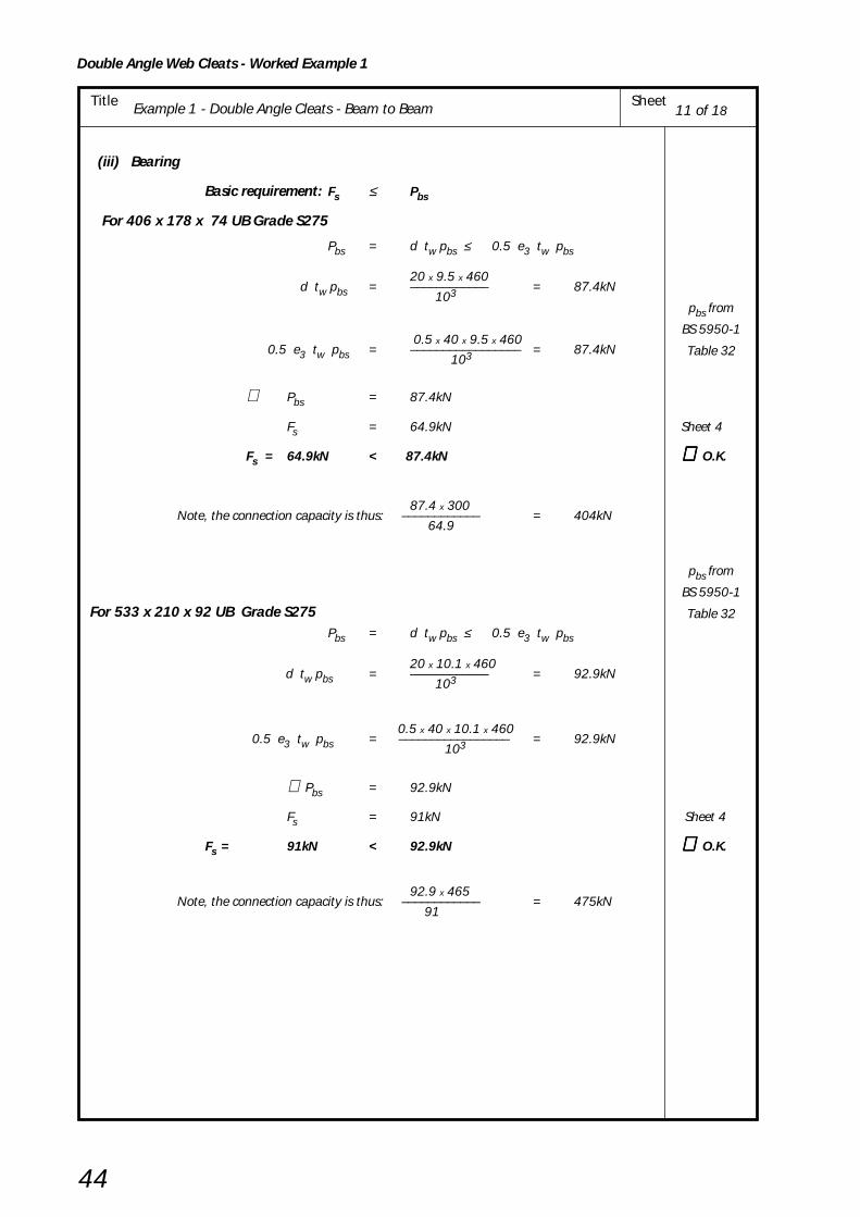
Double Angle Web Cleats - Worked Example 1
44
Title Example 1 - Double Angle Cleats - Beam to Beam Sheet
(iii) Bearing
Basic requirement: Fs ≤ Pbs
For 406 x 178 x 74 UB Grade S275
Pbs = d tw pbs ≤ 0.5 e3 tw pbs
20 x 9.5 x 460 d tw pbs = –––––––––––– = 87.4kN
103
0.5 x 40 x 9.5 x 460 0.5 e3 tw pbs = ––––––––––––––––– = 87.4kN
103
∴ Pbs = 87.4kN
Fs = 64.9kN Sheet 4
Fs = 64.9kN < 87.4kN ∴∴∴∴∴ O.K.
87.4 x 300 Note, the connection capacity is thus: –––––––––––– = 404kN
64.9
For 533 x 210 x 92 UB Grade S275Pbs = d tw pbs ≤ 0.5 e3 tw pbs
20 x 10.1 x 460 d tw pbs = –––––––––––– = 92.9kN
103
0.5 x 40 x 10.1 x 460 0.5 e3 tw pbs = ––––––––––––––––– = 92.9kN
103
∴ Pbs = 92.9kN
Fs = 91kN Sheet 4
Fs = 91kN < 92.9kN ∴∴∴∴∴ O.K.
92.9 x 465 Note, the connection capacity is thus: –––––––––––– = 475kN
91
pbs from
BS 5950-1
Table 32
pbs from
BS 5950-1
Table 32
11 of 18

Double Angle Web Cleats - Worked Example 1
45
Title Example 1 - Double Angle Cleats - Beam to Beam Sheet
AvN = AvFrom sheet 10
483
50
SectionCritical
F = 465kN
v
t =101
40
c = 110
(n – 1)p=350
e =93b
e = 40t
= 300kN
(n – 1)p=210
e =113b
t =101
e = 40t
c = 110
x = 20N
g =50be = 403
Fv
Critical Section
12 of 18
CHECK 5: Supported Beam - Capacity at a notch
Shear and Bending Interaction at the notch
For 406 x 178 x 74 UB Grade S275
Double bolt line. Find whether:
xN < 2d or xN ≥ 2d
2d = 2 x 20 = 40mm
xN = 20mm
since xN < 2d , requirement (b) applies
Basic requirement:
(b) max ( Fv(t1+c), Fv(t1+e3+gb)) ≤ McN
McN = McC = 89.1kNm from Check 4 (sheet 9)
300 x (10+110) Fv(t1+c) = ––––––––––––– = 36.0kNm
103
300 x (10+40+50) Fv(t1+e3+gb) = ––––––––––––– = 30.0kNm
103
Eccentric moment Fv ( t1 + c ) = 36kNm < 89.1kNm ∴∴∴∴∴ O.K.
For 533 x 210 x 92 Grade S275Single bolt line
(a) Basic requirement: Fv ( t1 + c ) ≤ McN
For low shear condition:
Fv ≤ 0.75 PvN
PvN = 0.6 py AvN
AvN = (et + (n – 1) p + eb)tw
= 4878mm2
PvN = 0.6 py AvN
0.6 x 275 x 4878= –––––––––––––––
103
= 805kN
0.75PvN = 0.75 x 805 = 604kN
Fv = 465kN ≤ 604kN
∴ ∴ ∴ ∴ ∴ low shear criteria for bending applies
∴ McN = Py ZN
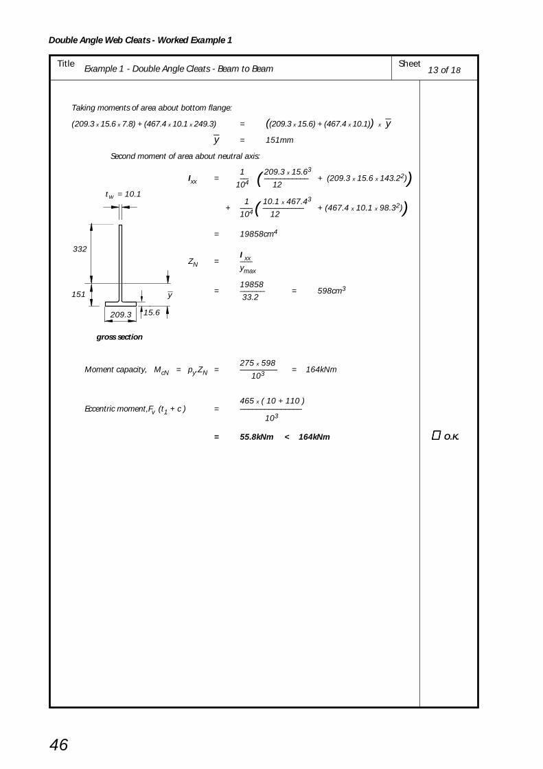
Double Angle Web Cleats - Worked Example 1
46
Title Example 1 - Double Angle Cleats - Beam to Beam Sheet
Taking moments of area about bottom flange:
(209.3 x 15.6 x 7.8) + (467.4 x 10.1 x 249.3) = ((209.3 x 15.6) + (467.4 x 10.1)) x yy = 151mm
Second moment of area about neutral axis:
1 209.3 x 15.63Ixx = –– ( ––––––––––– + (209.3 x 15.6 x 143.22)) 104 12
1 10.1 x 467.43 + ––– ( –––––––––– + (467.4 x 10.1 x 98.32))104 12
= 19858cm4
I xxZN = –––ymax
19858= –––––– = 598cm3
33.2
275 x 598Moment capacity, McN = py.ZN = ––––––––– = 164kNm
103
465 x ( 10 + 110 )Eccentric moment,Fv (t1 + c ) = –––––––––––––––
103
= 55.8kNm < 164kNm ∴ ∴ ∴ ∴ ∴ O.K.
t = 10.1w
332
151 y
15.6209.3
gross section
13 of 18
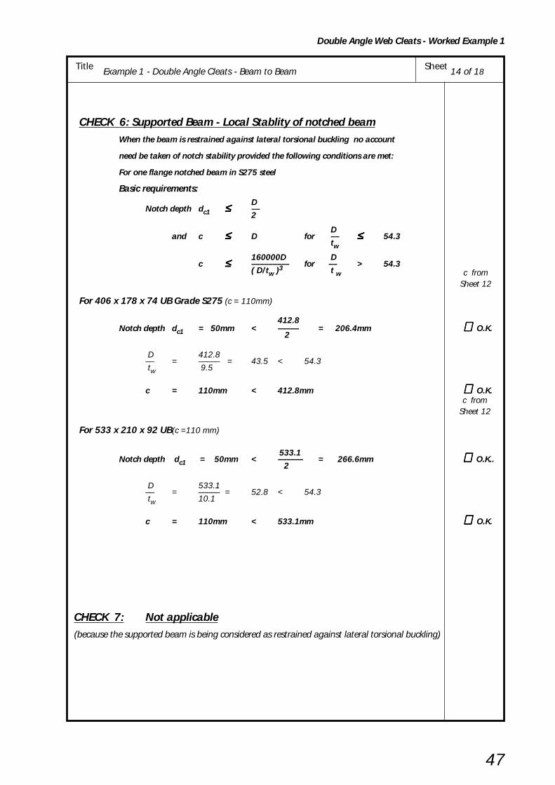
Double Angle Web Cleats - Worked Example 1
47
Title Example 1 - Double Angle Cleats - Beam to Beam Sheet
CHECK 6: Supported Beam - Local Stablity of notched beamWhen the beam is restrained against lateral torsional buckling no account
need be taken of notch stability provided the following conditions are met:
For one flange notched beam in S275 steel
Basic requirements:D
Notch depth dc1 ≤≤≤≤≤ ––2
Dand c ≤≤≤≤≤ D for –– ≤≤≤≤≤ 54.3
tw160000D D
c ≤≤≤≤≤ ––––––––– for –– > 54.3( D/tw )3 t w
For 406 x 178 x 74 UB Grade S275 (c = 110mm)
412.8Notch depth dc1 = 50mm < ––––– = 206.4mm ∴∴∴∴∴ O.K.
2
D 412.8–– = ––––– = 43.5 < 54.3 tw 9.5
c = 110mm < 412.8mm ∴∴∴∴∴ O.K.
For 533 x 210 x 92 UB(c =110 mm)
533.1Notch depth dc1 = 50mm < –––––– = 266.6mm ∴ ∴ ∴ ∴ ∴ O.K..
2
D 533.1–– = ––––– = 52.8 < 54.3 tw 10.1
c = 110mm < 533.1mm ∴∴∴∴∴ O.K.
CHECK 7: Not applicable (because the supported beam is being considered as restrained against lateral torsional buckling)
c fromSheet 12
c fromSheet 12
14 of 18

Double Angle Web Cleats - Worked Example 1
48
Title Example 1 - Double Angle Cleats - Beam to Beam Sheet
CHECK 8: Supporting Beam - Bolt Group
Basic requirement: Fv ≤ Σ Σ Σ Σ Σ Ps
For 406 x 178 x 74 UB
Shear capacity of single bolt, Ps = ps As
375 x 245 For M20 grade 8.8 bolts, Ps = ––––––––
103
= 91.9kN
But for top pair of bolts Ps is the lesser of ps As or 0.5 kbs e1 tc pbs
1.0 x 40 x 10 x 460 0.5 kbs e1 tc pbs = 0.5 x ––––––––––––––––
103
= 92kN ∴ use 91.9kN
Σ Ps = 8 x 91.9 = 735kN
Fv = 300kN < 735kN ∴∴∴∴∴ O.K.
For 533 x 210 x 92 UB
0.5 kbs e1 tc pbs = 92kN ∴ use 91.9kN
Σ Ps = 12 x 91.9 = 1103kN
FV = 465kN < 1103kN ∴∴∴∴∴ O.K.
e = 40
533 x 210 x 92 UB
465kN
1
610 x 229 x 140 UBGrade S275
ps fromBS 5950-1Table 30.
SeeBolt capacitiesyellow pagesTable H.49
pbs fromBS 5950-1Table 32.
300kN
610 x 229 x 140 UBGrade S275
e = 40
406 x 178 x 74 UB
1
15 of 18

Double Angle Web Cleats - Worked Example 1
49
Title Example 1 - Double Angle Cleats - Beam to Beam Sheet
CHECK 9: Supporting Beam - Connecting elements Shear and bearing of cleats connected to supporting beam
Fv(i) Basic requiremenf for shear: –– ≤ Pv.min2 For 406 x 178 x 74 UB
Shear capacity of one angle cleat, Pv.min is the smaller of plain shear capacity Pv and block shear capacity Pr
Plain shear Pv = min ( 0. 6 py A v , 0.7 py Ke A v.net )Shear area, Av = 0.9 (2e1 + (n – 1) p ) tc
= 0.9 (80 + 210 ) x 10 = 2610mm2
Net area, Av.net = Av – n Dh tc= 2610 – (4 x 22 x l0) = 1730mm2
0.6 x 275 x 26100.6 py Av = ––––––––––––––– = 431kN
103
0.7 x 275 x 1.2 x17300.7 py Ke A v.net = –––––––––––––––––– = 400kN
103
∴ Pv = 400kN
Block shear Pr = 0.6py tc ( Lv + Ke ( Lt – kDh ))Lv = e1 + (n – 1)p = 40 + 210 = 250mm
Lt = e2 = 40mm
k = 0.5 (for single line of bolts)
Ke = 1.2 (for S275)
0.6 x 275 x 10 (250 + 1.2(40 – 0.5 x 22))∴ Pr = ––––––––––––––––––––––––––––––––––––103
= 470kN∴ Pv.min = min (Pv , Pr )
= 400kNFv/2 = 150kN < 400kN ∴ ∴ ∴ ∴ ∴ O.K.
For 533 x 210 x 92 UBPlain shear Pv
Av = 0.9(80 + 350) x 10 = 3870mm2
Av.net = 3870 – (6 x 22 x l0) = 2550mm2
0.6 x 275 x 38700.6 py Av = ––––––––––––––– = 639kN
103
0.7 x 275 x 1.2 x 25500.7 py Ke A v.net = –––––––––––––––––– = 589kN
103
Pv = 589kN
Block shear Pr0.6 x 275 x 10 ( 390 + 1.2( 40 – 0.5 x 22) )
Pr = –––––––––––––––––––––––––––––––––––––– 103
= 701kN
Pv.min = min ( Pv , Pr )
= 589kNFv/2 = 233kN < 589kN ∴ ∴ ∴ ∴ ∴ O.K.
NOTE: Block shear checks have been shown here, but they are never critical for well proportioned cleats. However, if the bolt spacing is concentrated at one part of a cleat then these checks may be critical.
2
= 300kN
2
e1
1e
(n –1) p= 210
= 40
= 40Fv Fv
Fv
= 40
= 40
= 350(n – 1) p
e1
1e
= 465kN
22Fv Fv
Fv
16 of 18

Double Angle Web Cleats - Worked Example 1
50
Title Example 1 - Double Angle Cleats - Beam to Beam Sheet
Fv(ii) Basic requirement for bearing: –– ≤ ΣΣΣΣΣ Pbs2 For 406 x 178 x 74 UB
Bearing capacity, Pbs = kbsd tc pbs
but for top bolt Pbs = min ( kbsd tc pbs , 0.5kbs e1 tc pbs )
1.0 x 20 x 10 x 460kbsd tc pbs = –––––––––––––––– = 92kN
103
1.0 x 20 x 10 x 4600.5kbse1 tc pbs = –––––––––––––––– = 92kN
103
Σ Pbs = 3 x 92 + 92 = 368kN
Fv 300–– = –––– = 150kN < 368kN ∴ ∴ ∴ ∴ ∴ O.K. 2 2
For 533 x 210 x 92 UBBearing capacity as above
Σ Pbs = 5 x 92 + 92 = 552kN
Fv 465–– = –––– = 233kN < 552kN ∴∴∴∴∴ O.K.2 2
pbs fromBS 5950-1Table 32
17 of 18

Double Angle Web Cleats - Worked Example 1
51
Title Example 1 - Double Angle Cleats - Beam to Beam Sheet
py from
BS 5950-1
Table 9
pbs from
BS 5950-1
Table 32
CHECK 10 : Supporting Beam - Local CapacityLocal Shear & Bearing Capacity of beam web supporting two beams
Fv1A Fv2(i) Basic requirement for shear: ––– + ––– ≤ Pv 2 2
Fv1A Fv2 For double sided portion, ––– + ––– ≤ Pv 2 2
n2 4Fv1A = Fv1 –– = 465 x –– = 310kN n1 6
Shear capacity, Pv = min ( 0.6 py Av , 0.7 py Ke Av.net )
Gross shear area, Av = (et + (n2 – 1) p + eb ) twet = min ( et1 , 5d ) = 90mm
eb = min ( eb2 , g/2 , 5d ) = 55mm
Av = (90 + (4 – 1) 70 + 55) x 13.1 = 4651mm2
0.6 x 265 x 4651∴ 0.6 py Av = –––––––––––––––– = 740kN 103
Net shear area, Av.net = Av – n2 Dh tw
= 4651 – (4 x 22 x 13.1) = 3498mm2
0. 7 x 265 x 1.2 x 3498 ∴ 0.7py Ke Av.net = ––––––––––––––––––––– = 779kN 103
∴ Pv = 740kN
Fv1A Fv2 310 300––– + ––– = –––– + –––– = 305kN 2 2 2 2
305kN < 740kN ∴∴∴∴∴ O.K
Note: The above check is for local shear only; the effects of any global shear forces must also be considered.
Fv1/2Fv2/2(ii) Basic requirement for bearing: –––– + ––––– ≤ Pbs
n1 n2
Bearing capacity of beam web, Pbs = d tw pbs
20 x 13.1 x 460= ––––––––––––––––– = 121kN
103
Fv1/2Fv2/2
465/2300/2–––– + ––––– = ––––– + ––––– = 76kN
n1 n2
6 4
76kN < 121kN ∴∴∴∴∴ O.K
18 of 18
n = 4 n = 612
T = 22.1
1A
1B
e = 90 1p = 70pppp
g = 110
Fv
Fv
t1e = 90
e = 317.2 b2
F = 465kNF = 300kN v1v2

52
Double Angle Web Cleats - Worked Example 2
Title Example 2 - Double Angle Cleats – Beam to UC Column – Structural Integrity Sheet
BCSA
CALCULATIONSHEET
Calcs by
Title
Client
Checked by Date
Job NoJoints in Steel Construction - Simple Connections
Example 2 - Double Angle Cleats – Beam to UC Column – Structural Integrity
SCI/BCSA Connections Group
RS AM May 2002
DESIGN EXAMPLE 2
Check the following beam to column connections for the tie force shown.
Design Information:
Bolts: M20 8.8
Material: All S275 steel
1 of 8
2 - 150 x 90 x 10angle cleats (Type CB4)
Grade S275
2 - 90 x 90 x 10angle cleats (Type CA6)
Grade S275
5555
40
50
50 40
55 55
For cleat details
see Figure 4.4
and yellow pages
Table H.2
Sheet
504070
70
70
7070
40
50
10
370kNTie force
50 50
Tie force240kN
533 x 210 x 92 UBGrade S275
406 x 178 x 74 UBGrade S275
305 x 305 x 137 UCGrade S275

Double Angle Web Cleats - Worked Example 2
53
Title Example 2 - Double Angle Cleats – Beam to UC Column – Structural Integrity Sheet
CONNECTION DESIGN USING CAPACITY TABLES FROM THE YELLOW PAGES
406 x 178 x 74 UB Grade S275 533 x 210 x 92 UB Grade S275
Cleat type CB4 Grade S275 Cleat type CA6 Grade S275
Bolts M20 8.8 Bolts M20 8.8
From capacity table H.10 in yellow pages From capacity table H.9 in yellow pages
Connection tying capacity Connection tying capacity= 448kN > 240kN = 558kN > 370kN ∴ O.K.
The beam side of the connection The beam side of the connection
is adequate is adequate
Note:
(l) The tying capacity of the connection given in the tables in the yellow pages is the least valueobtained from CHECKS 11, 12 and 13. The values for CHECK 11 are based upon the largedisplacement analysis given in Appendix B.
(2) Beams connecting into a column web must also be checked for web bending as shown inCHECK 14 on sheet 7.
In the case of the 406UB illustrated, CHECK 14 gives the critical tie capacity unless the webis stiffened.
370kNTie force
Tie force240kN
533 x 210 x 92 UBGrade S275
406 x 178 x 74 UBGrade S275
305 x 305 x 137 UCGrade S275
Yellow pagesTables
H.10 & H.9
2 of 8

54
Double Angle Web Cleats - Worked Example 2
Title Example 2 - Double Angle Cleats – Beam to UC Column – Structural Integrity Sheet
SUMMARY OF FULL DESIGN CHECKS FOR EXAMPLE 2
Notes: (i) * ( ) A greater capacity for angle cleats can be obtained using the large displacement analysis described in Appendix B. It is an iterative procedure more suited to computation by computer.
(ii) The tie force values in the capacity tables are based on the large displacement analysis.
406UB (S275) 533UB (S275) 305UC (S275)Sheet
CHECKNos
CapacityApplied
CapacityApplied
CapacityApplied
Load Load Load
4 CHECK 11 333 240 492 370Structural Integrity (448)* (662)*- Connecting Elements - Tension capacity of
CRITICAL CHECKdouble angle cleats (kN) BEAM SIDE
5 & 6 CHECK 12 Tension (kN) 674 240 828 370Structural integrity Bearing (kN) 874 240 558 370
Not Applicable
- Supported Beam - Tension andbearing capacity of beam web
6 CHECK 13Structural integrity 588 240 882 370- Tension capacity of bolts (kN)
7 & 8 CHECK 14Structural integrity Not Applicable 392 240- Tying capacity of supporting column web (kN) CRITICAL CHECK
COLUMN SIDE
3 of 8

Double Angle Web Cleats - Worked Example 2
55
Title Example 2 - Double Angle Cleats – Beam to UC Column – Structural Integrity Sheet
CHECK 11 Structural Integrity - Connecting ElementsTension capacity of pair of web angle cleats
Basic requirement: Tie force ≤ Tying capacity of double angle web cleats
For 406 x 178 x 74 UB
Tying capacity of double angle web cleats
= 0.6 Le tc py (For S275 steel)
Effective net length of cleats is Le
Le = 2 ee + (n – 1) pe – n Dh
ee = e1 but ≤ e2 = 40mm
pe = p but ≤ 2e2 = 70mm
Le = (2 x 40) + (3 x 70) – (4 x 22) = 202mm
0.6 x 202 x 10 x 275 Tying capacity = ––––––––––––––––– = 333kN
103
Tie Force = 240kN < 333kN ∴ O.K.
For 533 x 210 x 92 UB
Tying capacity of double angle web cleats
= 0.6 Le tc py (For S275Steel)
Le = 2 ee + (n – 1) pe – n Dh
ee = e1 but ≤ e2 = 40mm
pe = p but ≤ 2e2 = 70mm
Le = (2 x 40) + (5 x 70) – (6 x 22) = 298mm
0.6 x 298 x 10 x 275 Tying capacity = ––––––––––––––––– = 492kN
103
Tie Force = 370kN < 492kN ∴ O.K.
e = 40
p = 70
70
70
e = 40
e = 40
1
1
Critical sections
2
Critical sections
1
1
e = 40
e = 40
70
70
p = 70
e = 40
70
70
2
4 of 8

56
Double Angle Web Cleats - Worked Example 2
Title Example 2 - Double Angle Cleats – Beam to UC Column – Structural Integrity Sheet
CHECK 12: Structural Integrity - Supported BeamTension & Bearing Capacity of Beam Web
(i) For Tension:
Basic requirement: Tie force ≤ Net tension capacity of beam web
For 406 x 178 x 74 UB S275 (double line of bolts)
Net tension capacity of beam web = Le tw py
Effective net length, Le = 2 ee + (n – 1) pe – n Dh
ee = (e3 + gb – Dh ) but ≤ et
= 68mm ≤ 90
pe = p but ≤ 2(e3 + gb – Dh )
= 70mm ≤ 2(90 – 22)
Le = (2 x 68) + (3 x70) – (4 x 22)
= 258mm
258 x 9.5 x 275Net tension capacity = ––––––––––––– = 674kN
103
Tie Force = 240kN < 674kN ∴ O.K.
For 533 x 210 x 92 UB Grade S275 (single line of bolts)
Net tension capacity of beam web = Le tw py
Effective net length, Le = 2 ee + (n – 1) pe – n Dh
ee = e3 but ≤ et
= 40mm ≤ 90
pe = p but ≤ 2e
= 70mm ≤ 2 x 40
Le = (2 x 40) + (5 x 70) – (6 x 22)
= 298mm
298 x 10.1 x 275Net tension capacity = –––––––––––––– = 828kN
103
Tie Force = 370kN < 828kN ∴ O.K.
Note: This value may not be the same as that given in capacity tables, where a double notched beamis assumed (i.e. et = 40mm).
e = 90
70
70
70 Tie force240kN
n rows of bolts
t
e + g = 90b3
370kNTie force
70
70
70
e = 40
70
70
n rows of bolts
e = 90t
3
See notebelow
See notebelow
5 of 8

Double Angle Web Cleats - Worked Example 2
57
Title Example 2 - Double Angle Cleats – Beam to UC Column – Structural Integrity Sheet
(ii) For bearing:
Basic requirement: Tie force ≤ Bearing capacity of beam web
For 406 x 178 x 74 UB Grade S275 (double line of bolts)
Bearing capacity of beam web = 3 n d tw pbs
but ≤ n(1.5d tw pbs + 0.5 e3 tw pbs)
3 x 4 x 20 x 9.5 x 4603 n d tw
pbs = –––––––––––––––––– = 1049kN 103
4(1.5 x 20 x 9.5 x 460 + 0.5 x 40 x 9.5 x 460)n(1.5d tw pbs + 0.5 e3 tw pbs) = ––––––––––––––––––––––––––––––––––––––
103= 874kN
∴ Bearing capacity of beam web = 874kN
Tie Force = 240kN < 874kN ∴ O.K.
For 533 x 210 x 92 UB Grade S275 (single line of bolts) Bearing capacity of beam web = 1.5 n d tw
pbs but ≤ 0.5n e3 tw pbs)
1.5 x 6 x 20 x 10.1 x 4601.5 n d tw
pbs = –––––––––––––––––– = 836kN 103
0.5 x 6 x 40 x 10.1 x 4600.5n e3 tw pbs = –––––––––––––––––– = 558kN
103
∴ Bearing capacity of beam web = 558kN
Tie Force = 370kN < 558kN ∴ O.K.
CHECK 13 : Structural Integrity - Tension Capacity of Bolts
Basic requirement : Tie Force ≤ Tension capacity of tension bolt group
Tension capacity = 2 n At ptr
ptr = reduced tension strength of bolt inpresence of extreme prying force
= 300N/mm2 for grade 8.8 bolts Appendix D
At = tensile stress area of bolt
= 245mm2
For 406 x 178 x 74 UB2 x 4 x 245 x 300
Tension capacity = –––––––––––––– = 588kN103
Tie Force = 240kN < 588kN ∴ O.K.
For 533 x 210 x 92 UB2 x 6 x 245 x 300
Tension capacity = –––––––––––––– = 882kN103
Tie Force = 370kN < 882 kN ∴ O.K.
pbs fromBS 5950-1Table 32
pbs fromBS 5950-1Table 32
Bolt capacitytables
Yellow pagesTable H.49
6 of 8
Tie ForceTension
bolt group

58
Double Angle Web Cleats - Worked Example 2
Title Example 2 - Double Angle Cleats – Beam to UC Column – Structural Integrity Sheet
CHECK 14: Structural lntegrity – Capacity of Supporting Column Web
Basic requirement: Tie Force ≤ Tying capacity of column web
Tying capacity 8 Mu= ––––– [ η
1 + 1.5(1 – β1)0.5 (1 – γ1)0.5 ]of column web 1 – β 1
Mu = moment capacity of column web per unit length
pu t w2
= –––––– 4
328 x 13.82= –––––––––– = 15.6kNm/mm
4 x 10³
(n – 1) p – n
Dh 2η1 = ––––––––––––––
dc
(4 –1) x 70 – 4
x 22
2= –––––––––––––––– = 0.673
246.7
gβ1 = –––
dc 110
= ––––– = 0.446 246.7
Dhγ1 = –––
dc
22= ––––– = 0.089
246.7
Tying capacity 8 x 15.6= ––––––––– [ 0.673 + 1.5(1 – 0.446)0.5
x (1 – 0.089)0.5 ]of column web 1 – 0.446
= 225.3 [ 0.673 + (1.116 x 0.954) ] = 392kN
Tie Force = 240kN < 392kN ∴ O.K.
305 x 305 x 137 UCGrade S275
d = 246.7
g = 110
t = 13.8w
c
Tie Force
(n-1)p
7 of 8

Double Angle Web Cleats - Worked Example 2
59
Title Example 2 - Double Angle Cleats – Beam to UC Column – Structural Integrity Sheet
If column web fails to satisfy the criteria shown on sheet 7 then sfiffeners fillet welded on one
side to the web and flanges would be required thus:
8 of 8

Double Angle Web Cleats - Worked Example 3
60
Title Example 3 - Double Angle Cleats - Beam to RHS column using Flowdrill Sheet
BCSA
CALCULATIONSHEET
Calcs by
Title
Client
Checked by Date
Job Sheet
Joints in Steel Construction - Simple Connections
Example 3 - Double Angle Cleats - Beam to RHS column using Flowdrill
SCI/BCSA Connections Group
RS ASM May 2002
DESIGN EXAMPLE 3Check the following beam to RHS column connection for the design forces shown using 8.8 boltsin Flowdrill threaded holes in the column.In this example it is assumed that the tying force is equal to the end reaction. However, dependingon how the floor beams are arranged, the tying force given by the formula in BS 5950-1 clause2.4.5.3 can sometimes be less.
Note: The connections should be checked independently for (i ) shear forces and (ii) Tie forcesand NOT for both the forces acting at the same time.The yellow pages should be used for initial selection of angle cleats.
Design Information:
Flowdrill: M20 8.8Ordinary bolts: M20 8.8
Column: S355Beams: S275
Angle cleats: S275
1 of 9
REF.
For cleat details
see Figure 4.4
& Yellow pages
Table H.2
50
2 - 150 x 90 x 10angle cleats (Type CB4)Grade S275
2 - 90 x 90 x 10angle cleats (Type CA6)Grade S275
Ordinary bolts Flowdrill
50 50 50
40
70
70
70
70
7040
10 Projection
300kN 465kN
406 x 178 x 74 UBGrade S275
300kNtie
force
40
70
70
70
250 x 250 x 12.5 RHS Grade S355
10 Projection
533 x 210 x 92 UB
Grade S275
465kNtie
force
40

Double Angle Web Cleats - Worked Example 3
61
Title Example 3 - Double Angle Cleats - Beam to RHS column using Flowdrill Sheet
CONNECTION DESIGN USING CAPACITY TABLES FROM THE YELLOW PAGES
406 x 178 x 74 UB Grade S275 533 x 210 x 92 UB Grade S275
Cleat type CBD Grade S275 Cleat type CAS Grade S275
Column Bolts Flowdrill M20 8.8 Column Bolts Flowdrill M20 8.8
Beam Bolts M20 8.8 Beam Bolts M20 8.8
From capacity table H.10 in yellow pages From capacity table H.9 in yellow pages
Connection vertical shear capacity Connection vertical shear capacity= 404kN > 300kN = 475kN > 465kN ∴ O.K
Minimum support thickness Minimum support thickness
= 4.6 mm < 12.5mm = 3.6mm < 12.5mm ∴ O.K.
Connection tying capacity Connection tying capacity= 448kN > 300kN = 558kN > 465kN ∴ O.K.
The beam side of the connection The beam side of the connection
is adequate is adequate
Note:
(l) The tying capacity of the connection given in the tables in the yellow pages is the least valueobtained from CHECKS 11, 12 and 13. The values for CHECK 11 are based upon the largedisplacement analysis given in Appendix B.
(2) Beams connecting into a column web or RHS wall must also be checked for web bending asshown in CHECK 15 on sheets 8 and 9.
2 of 9
Yellow pagesTables
H.10 & H.9
300kN 465kN
406 x 178 x 74 UBGrade S275
300kNtie
force
250 x 250 x 12.5 RHS Grade S355
533 x 210 x 92 UB
Grade S275
465kNtie
force
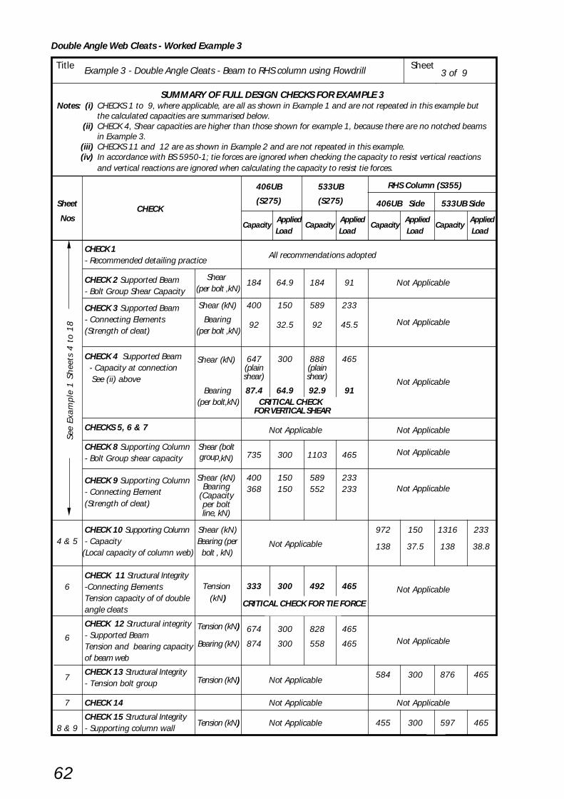
Double Angle Web Cleats - Worked Example 3
62
Title Example 3 - Double Angle Cleats - Beam to RHS column using Flowdrill Sheet3 of 9
SUMMARY OF FULL DESIGN CHECKS FOR EXAMPLE 3Notes: (i) CHECKS 1 to 9, where applicable, are all as shown in Example 1 and are not repeated in this example but
the calculated capacities are summarised below.(ii) CHECK 4, Shear capacities are higher than those shown for example 1, because there are no notched beams
in Example 3.(iii) CHECKS 11 and 12 are as shown in Example 2 and are not repeated in this example.
(iv) In accordance with BS 5950-1; tie forces are ignored when checking the capacity to resist vertical reactionsand vertical reactions are ignored when calculating the capacity to resist tie forces.
See
Exa
mpl
e 1
Sh
eets
4 t
o 1
8
406UB 533UB RHS Column (S355)
Sheet CHECK
(S275) (S275) 406UB Side 533UB Side
Nos
CHECK 1- Recommended detailing practice
All recommendations adopted
CHECK 2 Supported Beam Shear184 64.9 184 91 Not Applicable
- Bolt Group Shear Capacity (per bolt ,kN)
CHECK 3 Supported Beam Shear (kN) 400 150 589 233
- Connecting Elements Bearing92 32.5 92 45.5 Not Applicable
(Strength of cleat) (per bolt ,kN)
CHECK 4 Supported Beam 647 300 888 465 - Capacity at connection
Shear (kN)(plain (plain
See (ii) above shear) shear)Not Applicable
Bearing 87.4 64.9 92.9 91 (per bolt,kN) CRITICAL CHECK
FOR VERTICAL SHEAR
CHECKS 5, 6 & 7 Not Applicable Not Applicable
CHECK 8 Supporting Column Shear (bolt735 300 1103 465 Not Applicable
- Bolt Group shear capacity group,kN)
CHECK 9 Supporting Column Shear (kN) 400 150 589 233Not Applicable- Connecting Element
Bearing 368 150 552 233
(Strength of cleat)(Capacityper boltline, kN)
CHECK 10 Supporting Column Shear (kN) 972 150 1316 2334 & 5 - Capacity Bearing (per Not Applicable 138 37.5 138 38.8
(Local capacity of column web) bolt , kN)
CHECK 11 Structural IntegrityTension 333 300 492 4656 -Connecting Elements Not Applicable
Tension capacity of of double (kN) CRITICAL CHECK FOR TIE FORCE
angle cleats
CHECK 12 Structural integrity Tension (kN) 674 300 828 4656 - Supported Beam
Tension and bearing capacity Bearing (kN) 874 300 558 465 Not Applicable
of beam web
7CHECK 13 Structural Integrity
Tension (kN) Not Applicable584 300 876 465
- Tension bolt group
7 CHECK 14 Not Applicable Not Applicable
CHECK 15 Structural Integrity8 & 9 - Supporting column wall
Tension (kN) Not Applicable 455 300 597 465
Capacity
Applied Capacity
Applied Capacity
Applied Capacity
Applied Load Load Load Load

Double Angle Web Cleats - Worked Example 3
63
Title Example 3 - Double Angle Cleats - Beam to RHS column using Flowdrill Sheet
CHECK 10 : Supporting Column - Local Capacity Shear & Bearing Capacity of column wall
Fv(i) Basic requirement for shear: –– ≤ Pv2
For 406 x 178 x 74 UB side
Shear capacity, Pv = min ( 0.6 py Av , 0.7 py Ke Av.net )
Gross shear area, Av = (et + (n – 1) p + eb ) tw
eb = smaller of g/2 and 5 d = 55mm
et = smaller of et1 and 5 d
since the connection is not near the top of column et1 is not applicable
et = 5d = 5 x 20 = 100mm
Av = (100 + (4 – 1) 70 + 55) x 12.5 = 4563mm2
0.6 x 355 x 45630.6 py Av = –––––––––––––––– = 972kN
103
Net shear area, Av.net = Av – n Dh twfor FLOWDRILL connections Dh = bolt diameter = 20mm
Av.net = 4563 – (4 x 20 x 12.5) = 3563mm2
0. 7 x 355 x 1.1 x 35630.7 py Ke Av.net = ––––––––––––––––––––– = 974kN
103
∴ Pv = 972kN
Fv––– = 150kN < 972kN ∴∴∴∴∴ O.K. 2
RHS Column Grade S355
Critical sections
2
wall thickness wt = 12.5mm g=110
= 150kNFv
2Fv
4 of 9
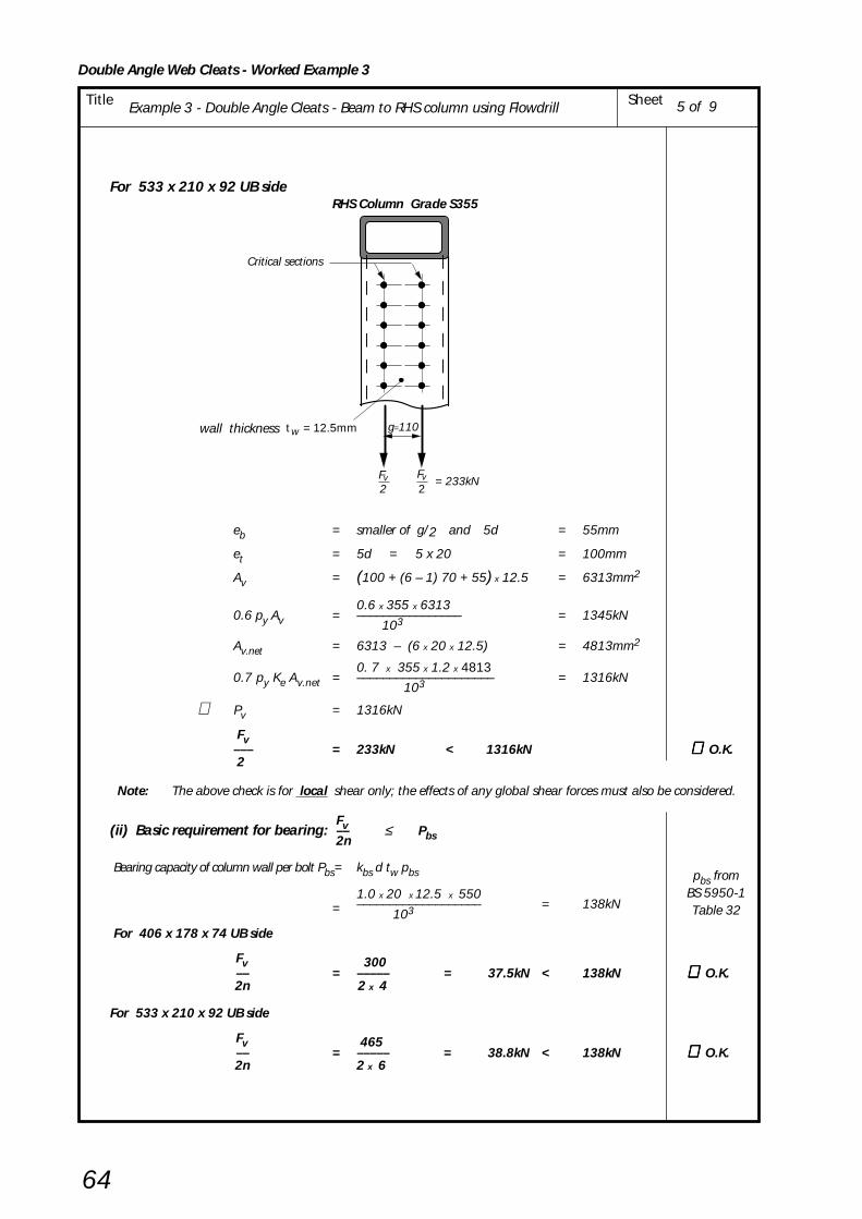
Double Angle Web Cleats - Worked Example 3
64
Title Example 3 - Double Angle Cleats - Beam to RHS column using Flowdrill Sheet
For 533 x 210 x 92 UB side
eb = smaller of g/2 and 5d = 55mm
et = 5d = 5 x 20 = 100mm
Av = (100 + (6 – 1) 70 + 55) x 12.5 = 6313mm2
0.6 x 355 x 63130.6 py Av = –––––––––––––––– = 1345kN
103
Av.net = 6313 – (6 x 20 x 12.5) = 4813mm2
0. 7 x 355 x 1.2 x 48130.7 py Ke Av.net = ––––––––––––––––––––– = 1316kN
103
∴ Pv = 1316kN
Fv––– = 233kN < 1316kN ∴∴∴∴∴ O.K. 2
Note: The above check is for local shear only; the effects of any global shear forces must also be considered.
Fv(ii) Basic requirement for bearing: –– ≤ Pbs2n
Bearing capacity of column wall per bolt Pbs= kbs d tw pbs
1.0 x 20 x 12.5 x 550= ––––––––––––––––––– = 138kN
103
For 406 x 178 x 74 UB side
Fv 300 –– = ––––– = 37.5kN < 138kN ∴∴∴∴∴ O.K. 2n 2 x 4
For 533 x 210 x 92 UB side
Fv 465 –– = ––––– = 38.8kN < 138kN ∴∴∴∴∴ O.K. 2n 2 x 6
5 of 9
pbs fromBS 5950-1Table 32
RHS Column Grade S355
Critical sections
2
wall thickness wt = 12.5mm g=110
= 233kNFv
2Fv

Double Angle Web Cleats - Worked Example 3
65
Title Example 3 - Double Angle Cleats - Beam to RHS column using Flowdrill Sheet 6 of 9
CHECK 11 Structural Integrity - Connecting Elements Tension capacity of pair of web angle cleats
This check is identical to CHECK 11 in Example 2
Basic requirement: Tie force ≤ tying capacity of double angle web cleats
For 406 x 178 x 74UB Side
Tying capacity of double angle cleats = 333kN
Tie Force = 300kN < 333kN ∴∴∴∴∴ O.K.
For 533 x 210 x 92UB Side
Tying capacity of double angle cleats = 492kN
Tie Force = 465kN < 492kN ∴∴∴∴∴ O.K.
CHECK 12 Structural Integrity - Supported Beam Tension and Bearing Capacity of the Beam Web
This check is identical to CHECK 12 in Example 2
(i) For Tension.
Basic requirement: Tie force ≤ net tension capacity of beam webs
For 406 x 178 x 74UB
Net tension capacity of beam web = 674kN
Tie Force = 300kN < 674kN ∴∴∴∴∴ O.K.
For 533 x 210 x 92UB
Net tension capacity of beam web = 828kN
Tie Force = 465kN < 828kN ∴∴∴∴∴ O.K.
(ii) For Bearing.
Basic requirement: Tie force ≤ bearing capacity of beam webs
For 406 x 178 x 74UB
Bearing capacity of beam web = 874kN
Tie Force = 300kN < 874kN ∴∴∴∴∴ O.K.
For 533 x 210 x 92UB
Bearing capacity of beam web = 558kN
Tie Force = 465kN < 558kN ∴∴∴∴∴ O.K.
Example 2 DACsheet 4 of 8
Example 2 DACsheet 4 of 8
Example 2 DACsheet 5 of 8
Example 2 DACsheet 5 of 8
Example 2 DACsheet 6 of 8
Example 2 DACsheet 6 of 8
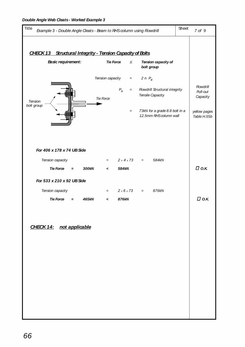
Double Angle Web Cleats - Worked Example 3
66
Title Example 3 - Double Angle Cleats - Beam to RHS column using Flowdrill Sheet 7 of 9
CHECK 13 Structural Integrity - Tension Capacity of Bolts
Basic requirement: Tie Force ≤ Tension capacity ofbolt group
Tension capacity = 2 n Psi
Psi = Flowdrill Structural integrity
Tensile Capacity
= 73kN for a grade 8.8 bolt in a 12.5mm RHS column wall
For 406 x 178 x 74 UB Side
Tension capacity = 2 x 4 x 73 = 584kN
Tie Force = 300kN < 584kN ∴∴∴∴∴ O.K.
For 533 x 210 x 92 UB Side
Tension capacity = 2 x 6 x 73 = 876kN
Tie Force = 465kN < 876kN ∴ ∴ ∴ ∴ ∴ O.K.
CHECK 14: not applicable
Tie ForceTension
bolt group
FlowdrillPull-outCapacity
yellow pagesTable H.55b

Double Angle Web Cleats - Worked Example 3
67
Title Example 3 - Double Angle Cleats - Beam to RHS column using Flowdrill Sheet
CHECK 15: Structural lntegrity – Capacity of Supporting Column Wall (RHS)
Basic requirement: Tie Force ≤ Tying capacity of RHS column wall
For 406 x 178 x 74 UB Side
Tying capacity 8 Mu= ––––– [ η
1 + 1.5(1 – β1)0.5 (1 – γ1)0.5 ]of column wall 1 – β 1
Mu = moment capacity of RHS column wall per unit length
pu t w2
= –––––– 4
392 x 12.52= –––––––––– = 15.3kNm/mm
4 x 10³
Dh = 20mm (Bolt diameter for Flowdrill)
(n – 1) p – n
Dh 2η1 = ––––––––––––––
B – 3tw
(4 –1) 70 – 4
x 20 2= –––––––––––––––– = 0.80
250 – 3 x 12.5
gβ1 = ––––––
B – 3tw 110
= ––––– = 0.518 212.5
Dhγ1 = ––––––
B – 3tw 20
= ––––– = 0.094212.5
Tying capacity 8 x 15.3= ––––––––– [ 0.8 + 1.5(1 – 0.518)0.5
x (1 – 0.094)0.5 ]of column wall 1 – 0.518
= 253.9 [ 0.8 + 1.041 x 0.952 ] = 455kN
Tie Force = 300kN < 455kN ∴∴∴∴∴ O.K.
8 of 9
Tie Force
g = 110
t = 12.5 w
B = 250
p (n-1)p
250 x 250 x 12.5 RHSGrade S355

Double Angle Web Cleats - Worked Example 3
68
Title Example 3 - Double Angle Cleats - Beam to RHS column using Flowdrill Sheet
For 533 x 210 x 92 UB Side
(n – 1) p – n
Dn 2η1 = ––––––––––––––
B – 3tw
(6–1) 70 – 6
x 20 2= –––––––––––––––– = 1.36
250 – 3 x 12.5
Tying capacity 8 Mu= ––––– [ η
1 + 1.5(1 – β1)0.5 (1 – γ1)0.5 ]of column wall 1– β 1
8 x 15.3= ––––––––– [ 1.36 + 1.5(1 – 0.518)0.5
x (1 – 0.094)0.5 ] 1 – 0.518
= 253.9 [ 1.36 + 1.041 x 0.952 ] = 597kN
Tie Force = 465kN < 597kN ∴∴∴∴∴ O.K.
9 of 9
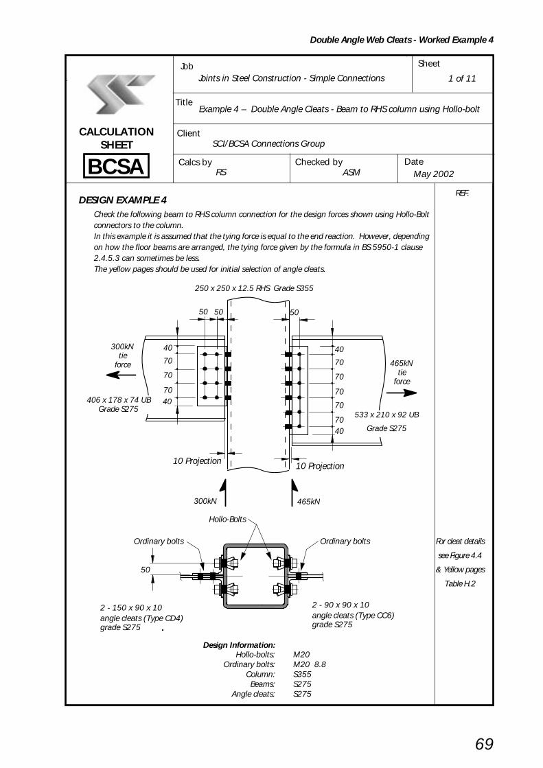
Example 4 – Double Angle Cleats - Beam to RHS column using Hollo-bolt SheetTitle
Double Angle Web Cleats - Worked Example 4
69
BCSA
CALCULATIONSHEET
Calcs by
Title
Client
Checked by Date
Job Sheet
Joints in Steel Construction - Simple Connections
Example 4 – Double Angle Cleats - Beam to RHS column using Hollo-bolt
SCI/BCSA Connections Group
RS ASM May 2002
DESIGN EXAMPLE 4Check the following beam to RHS column connection for the design forces shown using Hollo-Boltconnectors to the column.In this example it is assumed that the tying force is equal to the end reaction. However, dependingon how the floor beams are arranged, the tying force given by the formula in BS 5950-1 clause2.4.5.3 can sometimes be less.The yellow pages should be used for initial selection of angle cleats.
Design Information:Hollo-bolts: M20
Ordinary bolts: M20 8.8Column: S355Beams: S275
Angle cleats: S275
1 of 11
REF.
50 50 50
40
70
70
70
70
7040
10 Projection
300kN 465kN
406 x 178 x 74 UBGrade S275
300kNtie
force
40
70
70
70
250 x 250 x 12.5 RHS Grade S355
10 Projection
533 x 210 x 92 UB
Grade S275
465kNtie
force
40
50
2 - 150 x 90 x 10angle cleats (Type CD4)grade S275
2 - 90 x 90 x 10angle cleats (Type CC6)grade S275
Hollo-Bolts
Ordinary bolts Ordinary bolts For cleat details
see Figure 4.4
& Yellow pages
Table H.2
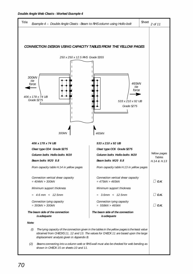
CONNECTION DESIGN USING CAPACITY TABLES FROM THE YELLOW PAGES
406 x 178 x 74 UB 533 x 210 x 92 UB
Cleat type CD4 Grade S275 Cleat type CC6 Grade S275
Column bolts Hollo-bolts M20 Column bolts Hollo-bolts M20
Beam bolts M20 8.8 Beam bolts M20 8.8
From capacity table H.14 in yellow pages From capacity table H.13 in yellow pages
Connection vertical shear capacity Connection vertical shear capacity= 404kN > 300kN = 475kN > 465kN ∴ O.K.
Minimum support thickness Minimum support thickness
= 4.6 mm < 12.5mm = 3.6mm < 12.5mm ∴ O.K.
Connection tying capacity Connection tying capacity= 393kN > 300kN = 558kN > 465kN ∴ O.K.
The beam side of the connection The beam side of the connection is adequate is adequate
Note:
(l) The tying capacity of the connection given in the tables in the yellow pages is the least valueobtained from CHECKS 11, 12 and 13. The values for CHECK 11 are based upon the largedisplacement analysis given in Appendix B.
(2) Beams connecting into a column web or RHS wall must also be checked for web bending asshown in CHECK 15 on sheets 10 and 11.
300kN 465kN
406 x 178 x 74 UBGrade S275
300kNtie
force
250 x 250 x 12.5 RHS Grade S355
533 x 210 x 92 UB
Grade S275
465kNtie
force
2 of 11
Yellow pagesTables
H.14 & H.13
Example 4 – Double Angle Cleats - Beam to RHS column using Hollo-bolt SheetTitle
Double Angle Web Cleats - Worked Example 4
70
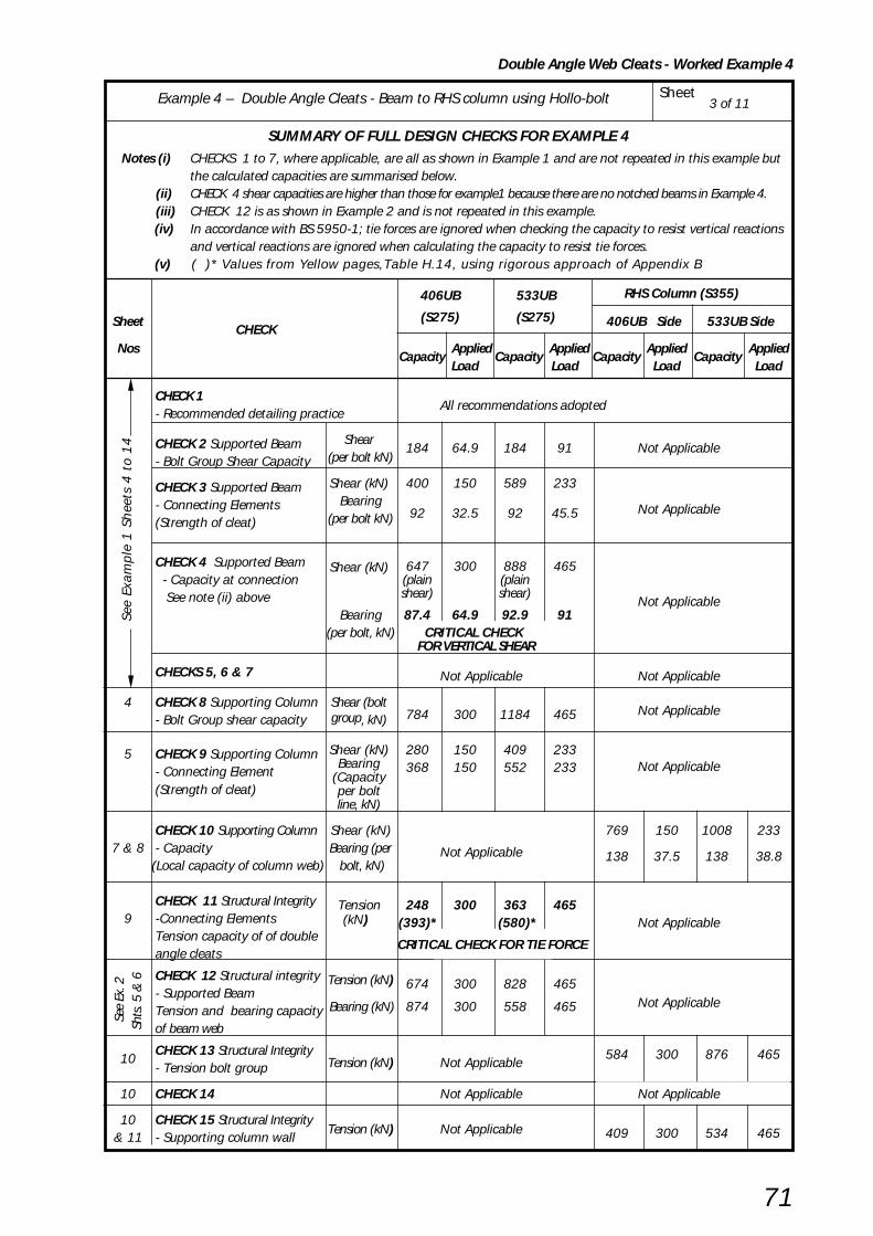
3 of 11Example 4 – Double Angle Cleats - Beam to RHS column using Hollo-bolt Sheet
Double Angle Web Cleats - Worked Example 4
71
SUMMARY OF FULL DESIGN CHECKS FOR EXAMPLE 4 Notes (i) CHECKS 1 to 7, where applicable, are all as shown in Example 1 and are not repeated in this example but
the calculated capacities are summarised below. (ii) CHECK 4 shear capacities are higher than those for example1 because there are no notched beams in Example 4. (iii) CHECK 12 is as shown in Example 2 and is not repeated in this example.
(iv) In accordance with BS 5950-1; tie forces are ignored when checking the capacity to resist vertical reactionsand vertical reactions are ignored when calculating the capacity to resist tie forces.
(v) ( )* Values from Yellow pages,Table H.14, using rigorous approach of Appendix B
406UB 533UB RHS Column (S355)
Sheet CHECK
(S275) (S275) 406UB Side 533UB Side
Nos Capacity
Applied Capacity
Applied Capacity
Applied Capacity
AppliedLoad Load Load Load
CHECK 1- Recommended detailing practice
All recommendations adopted
CHECK 2 Supported Beam Shear184 64.9 184 91 Not Applicable
- Bolt Group Shear Capacity (per bolt kN)
CHECK 3 Supported Beam Shear (kN) 400 150 589 233
- Connecting Elements Bearing92 32.5 92 45.5 Not Applicable
(Strength of cleat) (per bolt kN)
CHECK 4 Supported Beam 647 300 888 465 - Capacity at connection
Shear (kN)(plain (plain
See note (ii) above shear) shear)Not Applicable
Bearing 87.4 64.9 92.9 91 (per bolt, kN) CRITICAL CHECK
FOR VERTICAL SHEAR
CHECKS 5, 6 & 7 Not Applicable Not Applicable
4 CHECK 8 Supporting Column Shear (bolt784 300 1184 465 Not Applicable
- Bolt Group shear capacity group, kN)
5 CHECK 9 Supporting Column Shear (kN) 280 150 409 233Not Applicable- Connecting Element
Bearing 368 150 552 233
(Strength of cleat)(Capacityper boltline, kN)
CHECK 10 Supporting Column Shear (kN) 769 150 1008 2337 & 8 - Capacity Bearing (per Not Applicable 138 37.5 138 38.8
(Local capacity of column web) bolt, kN)
CHECK 11 Structural Integrity Tension 248 300 363 4659 -Connecting Elements (393)* (580)* Not Applicable
Tension capacity of of double (kN)
CRITICAL CHECK FOR TIE FORCE
angle cleats
CHECK 12 Structural integrity Tension (kN) 674 300 828 465- Supported BeamTension and bearing capacity
Bearing (kN) 874 300 558 465 Not Applicable
of beam web
10CHECK 13 Structural Integrity
Tension (kN) Not Applicable584 300 876 465
- Tension bolt group
10 CHECK 14 Not Applicable Not Applicable
10 CHECK 15 Structural Integrity& 11 - Supporting column wall
Tension (kN) Not Applicable 409 300 534 465
See
Exa
mpl
e 1
Sh
eets
4 t
o 1
4 S
ee E
x. 2
Shts
. 5 &
6

Example 4 – Double Angle Cleats - Beam to RHS column using Hollo-bolt SheetTitle
Double Angle Web Cleats - Worked Example 4
72
4 of 11
CHECK 8: Supporting Column - Bolt Group
Basic requirement: Fv ≤ ΣΣΣΣΣ Ps
Shear capacity of single bolt, Ps = ps As
For M20 Hollo-bolts shear capacity Ps = 100kN
But for top pair of bolts, Ps = min (ps As , 0.5 kbs e1 tc pbs )(where kbs = 1.0)
For 406 x 178 x 74 UB
0.5 x 1.0 x 40 x 10 x 4600.5 kbs e1 tc pbs = –––––––––––––––––––– = 92kN
103
Σ Ps = 2 x 92 + 6 x 100 = 784kN
Fv = 300kN < 784kN ∴ O.K.
For 533 x 210 x 92 UB
Σ Ps = 2 x 92 + 10 x 100 = 1184kN
Fv = 465kN < 1184kN ∴ O.K.
e = 401
406 x 178 x 74 UB
250 x 250 x 12.5 RHS
300kN
e = 401
533 x 210 x 92 UB
250 x 250 x 12.5 RHS
465kN
Yellow pages
Table H.56

Example 4 – Double Angle Cleats - Beam to RHS column using Hollo-bolt SheetTitle
Double Angle Web Cleats - Worked Example 4
73
CHECK 9: Supporting Beam - Connecting elements Shear and bearing of cleats connected to supporting column
Fv(i) Basic requiremenf for shear: –– ≤ Pv.min2 For 406 x 178 x 74 UB
Shear capacity of one angle cleat, Pv.min is the smaller of plain shear capacity Pv andblock shear capacity Pr
Plain shear, Pv = min (0. 6 py A v or 0.7 py Ke A v.net )Shear area, Av = 0.9 (2e1 + (n – 1) p ) tc
= 0.9 (80 + 210 ) x 10 = 2610mm2
Net area, Av.net = Av – n Dh tc for Hollo-Bolt connections Dh = 35mm
Av.net = 2610 – (4 x 35 x l0) = 1210mm2
0.6 x 275 x 26100.6 py Av = ––––––––––––––– = 431kN
103
0.7 x 275 x 1.2 x 12100.7 py Ke A v.net = –––––––––––––––––– = 280kN
103
∴ Pv = 280kN
Block shear, Pr = 0.6 py tc (Lv + Ke (Lt – k Dh)Lv = (n – 1)p + e1 = 210 + 40 = 250mm
Lt = e2 = 40mm
Ke = 1.2 (for S275)
K = 0.5 (for single line of bolts)
Dh = 35mm (hole diameter for Hollo-bolt)
0.6 x 275 x 10 (250 + 1.2(40 – 0.5 x 35))∴ Pr = ––––––––––––––––––––––––––––––––––––– 103
= 457kN
Pv.min = min ( Pv , Pr ) = 280kN
Fv–– = 150kN < 280kN ∴ O.K. 2
For 533 x 210 x 92 UB Plain shear,
Av = 0.9(80 + 350) x 10 = 3870mm2
Av.net = 3870 – (6 x 35 x 10) = 1770mm2
0.6 x 275 x 38700.6 py Av = ––––––––––––––– = 639kN
103
0.7 x 275 x 1.2 x 17700.7 py Ke A v.net = –––––––––––––––––– = 409kN
103
∴ Pv = 409kN
0.6 x 275 x 10 (390 + 1.2(40 – 0.5 x 35)) Block shear, Pr = –––––––––––––––––––––––––––––––––––––
103= 688kN
Pv.min = min ( Pv , Pr ) = 409kN
Fv–– = 233kN < 409kN ∴ O.K. 2
2
F = 300kN
2
e1
1e
(n –1) p= 210
= 40
= 40Fv Fv
v
= 40
= 40
= 350(n – 1) p
e1
1e
F = 465kN
22Fv Fv
v
5 of 11
Dh fromYellow pages
Table H.2

Example 4 – Double Angle Cleats - Beam to RHS column using Hollo-bolt SheetTitle
Double Angle Web Cleats - Worked Example 4
74
Fv(ii) Basic requirement for bearing: –– ≤ ΣΣΣΣΣ Pbs2
For 406 x 178 x 74 UB
Bearing capacity, Pbs = kbs d tc pbs
but for top bolt, Pbs = min (kbs d tc pbs , 0.5kbs e1 tc pbs )
for Hollo-Bolt connections d = "nominal" bolt diameter = 20mm
1.0 x 20 x 10 x 460kbs d tc pbs = ––––––––––––––– = 92kN
103
0.5 x 1.0 x 40 x 10 x 4600.5kbs e1 tc pbs = ––––––––––––––––––– = 92kN
103
Σ Pbs = 3 x 92 + 92 = 368kN
Fv–– = 150kN < 368kN ∴ O.K.2
For 533 x 210 x 92 UB
Bearing capacities are as above
Σ Pbs = 5 x 92 + 92 = 552kN
Fv–– = 233kN < 552kN ∴ O.K.2
Yellow pagesTable H.61
pbs fromBS 5950-1Table 32
6 of 11

Example 4 – Double Angle Cleats - Beam to RHS column using Hollo-bolt SheetTitle
Double Angle Web Cleats - Worked Example 4
75
CHECK 10 : Supporting Column - Local Capacity Shear & Bearing Capacity of column wall
Fv(i) Basic requirement for shear: –– ≤ Pv2
For 406 x 178 x 74 UB side
Shear capacity, Pv = min (0.6 py Av , 0.7 py Ke A v.net )
Gross shear area, Av = (et + (n – 1) p + eb ) tw
eb = smaller of g/2 and 5 d = 55mm
et = smaller of et1 and 5 d
since the connection is not near the top of column et1 is not applicable
et = 5d = 5 x 20 = 100mm
Av = (100 + (4 – 1) 70 + 55) x 12.5 = 4563mm2
0.6 x 355 x 4563∴ 0.6 py Av = –––––––––––––––– = 972kN 103
Net shear area, Av.net = Av – n Dh tw
for Hollo-Bolt connections Dh = hole diameter = 35mm
Av.net = 4563 – (4 x 35 x 12.5) = 2813mm2
0. 7 x 355 x 1.1 x 2813∴ 0.7 py Ke A v.net = –––––––––––––––––––– = 769kN 103
∴ Pv = 769kN
Fv––– = 150kN < 769kN ∴ O.K.2
7 of 11
RHS Column Grade S355
Critical sections
2
wall thickness wt = 12.5mm g=110
= 150kNFv
2Fv
Dh from Yellow pagesTable H.61

Example 4 – Double Angle Cleats - Beam to RHS column using Hollo-bolt SheetTitle
Double Angle Web Cleats - Worked Example 4
76
For 533 x 210 x 92 UB side
eb = smaller of g/2 and 5d = 55mm
et = 5d = 5 x 20 = 100mm
Av = (100 + (6 – 1) 70 + 55) x 12.5 = 6313mm2
0.6 x 355 x 6313∴ 0.6 py Av = –––––––––––––––– = 1345kN 103
Av.net = 6313 – (6 x 35 x 12.5) = 3688mm2
0. 7 x 355 x 1.1 x 3688∴ 0.7 py Ke A v.net = –––––––––––––––––––– = 1008kN 103
∴ Pv = 1008kN
Fv––– = 233kN < 1008kN ∴ O.K.2
Note: The above check is for local shear only; the effects of any global shear forces must also be considered.
Fv(ii) Basic requirement for bearing: –– ≤ Pbs2n
Bearing capacity of column wall per bolt Pbs = kbs d tw pbs
1.0 x 20 x 12.5 x 550= –––––––––––––––––– = 138kN
103
For 406 x 178 x 74 UB side
Fv 300–––– = ––––– = 37.5kN < 138kN ∴ O.K. 2n 2 x 4
For 533 x 210 x 92 UB side
Fv 465–––– = ––––– = 38.8kN < 138kN ∴ O.K. 2n 2 x 6
8 of 11
pbs fromBS 5950-1Table 32
RHS Column Grade S355
Critical sections
2
wall thickness wt = 12.5mm g=110
= 233kNFv
2Fv

Example 4 – Double Angle Cleats - Beam to RHS column using Hollo-bolt SheetTitle
Double Angle Web Cleats - Worked Example 4
77
9 of 11
e = 40
p = 70
70
70
e = 40
e = 40
1
1
Critical sections
2
Critical sections
1
1
e = 40
e = 40
70
70
p = 70
e = 40
70
70
2
Yellow pagesTable H.14
Yellow pagesTable H.14
CHECK 11 Structural Integrity - Connecting ElementsTension capacity of pair of web angle cleats
Basic requirement: Tie force ≤ Tying capacity of double angle web cleats
For 406 x 178 x 74 UBTying capacity of double angle web cleats
= 0.6 Le tc py (For S275 steel)
Effective net length of cleats is Le
Le = 2 ee + (n – 1) pe – n Dh
ee = e1 but ≤ e2 = 40mm
pe = p but ≤ 2e2 = 70mm
Le = (2 x 40) + (3 x 70) – (4 x 35) = 150mm
0.6 x 150 x 10 x 275 Tying capacity = ––––––––––––––––– = 248kN
103
Tie Force = 300kN <| 248kN ∴ Fails
However, using the rigorous approach of Appendix B, the tying capacity is 393kN. (For this standard connection, the value is given in the yellow pages)
Tie Force = 300kN < 393kN ∴O.K.
For 533 x 210 x 92 UB
Tying capacity of double angle web cleats
= 0.6 Le tc py (For S275Steel)
Le = 2 ee + (n – 1) pe – n Dh
ee = e1 but ≤ e2 = 40mm
pe = p but ≤ 2e2 = 70mm
Le = (2 x 40) + (5 x 70) – (6 x 35) = 220mm
0.6 x 220 x 10 x 275 Tying capacity = ––––––––––––––––– = 363kN
103
Tie force = 465kN <| 363kN ∴ ∴ ∴ ∴ ∴ Fails
However, using the rigorous approach of Appendix B, the tying capacity is 580kN.
Tie Force = 465kN < 580kN ∴O.K.
Note: The tying capacity obtained by CHECK 11 is the same, for similar cleats, with a "single lineof bolts" or a "double line of bolts". The standard connection values, obtained from Table H.14 ofthe yellow pages,are CHECK 11 critical values (whereas the values tabulated in Table H.13 areCHECK 12(ii) values for these particular standard connections).
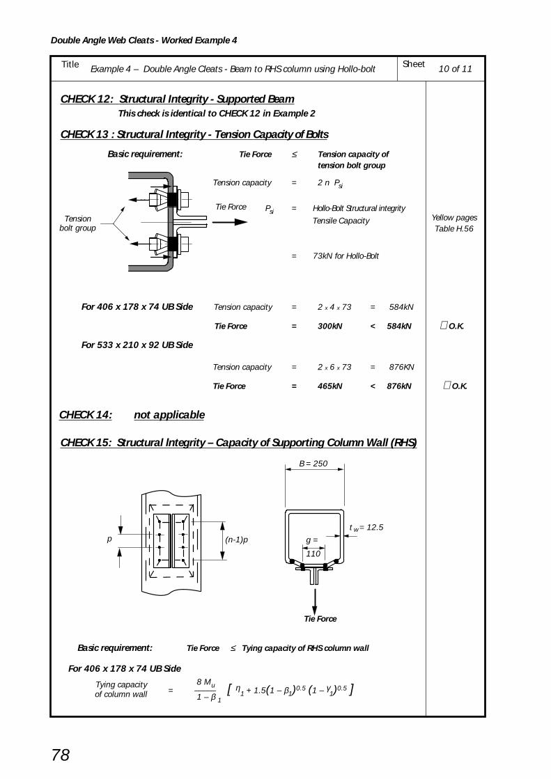
Example 4 – Double Angle Cleats - Beam to RHS column using Hollo-bolt SheetTitle
Double Angle Web Cleats - Worked Example 4
78
10 of 11
CHECK 12: Structural Integrity - Supported Beam This check is identical to CHECK 12 in Example 2
CHECK 13 : Structural Integrity - Tension Capacity of Bolts
Basic requirement: Tie Force ≤ Tension capacity oftension bolt group
Tension capacity = 2 n Psi
Psi = Hollo-Bolt Structural integrity
Tensile Capacity
= 73kN for Hollo-Bolt
For 406 x 178 x 74 UB Side Tension capacity = 2 x 4 x 73 = 584kN
Tie Force = 300kN < 584kN ∴O.K.
For 533 x 210 x 92 UB Side
Tension capacity = 2 x 6 x 73 = 876KN
Tie Force = 465kN < 876kN ∴O.K.
CHECK 14: not applicable
CHECK 15: Structural lntegrity – Capacity of Supporting Column Wall (RHS)
Basic requirement: Tie Force ≤ Tying capacity of RHS column wall
For 406 x 178 x 74 UB Side
Tying capacity 8 Mu= ––––– [ η
1 + 1.5(1 – β1)0.5 (1 – γ1)0.5 ]of column wall 1 – β 1
Yellow pagesTable H.56
Tie ForceTension
bolt group
Tie Force
g =
110
t = 12.5 w
B = 250
p (n-1)p

Example 4 – Double Angle Cleats - Beam to RHS column using Hollo-bolt SheetTitle
Double Angle Web Cleats - Worked Example 4
79
Mu = moment capacity of RHS column wall per unit length
pu t w2
392 x 12.52= –––––– = –––––––––– = 15.3kNm/mm
4 4 x 10³
Dh = 35mm (Hole diameter for Hollo-Bolt)
(n – 1) p – n
Dh 2η1 = ––––––––––––––
B – 3tw
(4 –1) 70 – 4
x 35
x 2= –––––––––––––––– = 0.659
250 – 3 x 12.5
gβ1 = ––––––
B – 3tw 110
= ––––– = 0.518 212.5
Dhγ1 = ––––––
B – 3tw 35
= ––––– = 0.165212.5
Tying capacity 8 x 15.3= ––––––––– [ 0.659 + 1.5(1 – 0.518)0.5
x (1 – 0.165)0.5 ]of column wall 1 – 0.518
= 253.9 [ 0.659 + (1.041 x 0.914) ] = 409kN
Tie Force = 300kN < 409kN ∴∴∴∴∴ O.K.
For 533 x 210 x 92 UB Side
(n – 1) p – n
Dh 2η1 = ––––––––––––––
B – 3tw
(6–1) 70 – 6
x 35 2= –––––––––––––––– = 1.152
250 – 3 x 12.5
Tying capacity 8 Mu= ––––– [ η
1 + 1.5(1 – β1)0.5 (1 – γ1)0.5 ]of column wall 1 – β 1
8 x 15.3= ––––––––– [ 1.152 + 1.5(1 – 0.518)0.5
x (1 – 0.165)0.5 ] 1 – 0.518
= 253.9 [ 1.152 + (1.041 x 0.914) ]= 534kN
Tie Force = 465kN < 534kN ∴∴∴∴∴ O.K.
11 of 11

Example 5 - Double Angle Cleats - Stability of an unrestrained notched beam SheetTitle
80
Double Angle Web Cleats - Worked Example 5
BCSA
CALCULATIONSHEET
Calcs by
Title
Client
Checked by Date
Job SheetJoints in Steel Construction - Simple Connections
Example 5 - Double Angle Cleats - Stability of an unrestrained notched beam
SCI/BCSA Connections Group
RS ASM May 2002
1 of 2
CHECK 7: Unrestrained Supported Beam - Overall Stability of Notched Beam(Unrestrained against lateral torsional buckling)
Basic requirement: Beams should be checked for lateral torsional buckling to BS 5950-1
clause 4.3.6 with a modified effective length (LE) which takes account of notches.
The following approach is only valid for c/Lb < 0.15 and dc1 /D < 0. 2 (beams with notches
outside these limits should be checked as tee sections, or stiffened)
Check the beam shown, which was designed as unrestrained over the span with an effective length of1.0Lb, when it has a single notch at each end, and a design moment of 200kNm due to UDL.
Beam 533 x 210 x 92 UB grade S355 Mx = 200kNm
Sx = 2360cm3
ry = 4.51cm properties obtained from published
x = 36.4 tables or derived from BS 5950-1 'Blue Book'
u = 0.873
v = 1 conservative
110c/Lb
= ––––– = 0.016 < 0.15 ∴ OK7000
50dc /D = –––––– = 0.094 < 0.2 ∴ OK 533.1
2c 1/2
Modified effective length, LE = Lb [1 + ––– (K2 + 2K)] Lb
K = Ko /λb
u v Lbλb = –––––– ry
0.873 x 1 x 7000λb = ––––––––––––––– = 135.5
45.1
λb > 30 ∴ Ko = go x but ≤ Kmax
Dd = 50c1
bL = 7000
c = 110 c = 110
533 x 210 x 92 UB S355 steel
SCI - P202
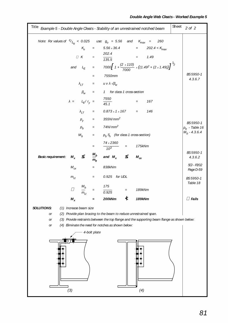
Example 5 - Double Angle Cleats - Stability of an unrestrained notched beam SheetTitle
81
Double Angle Web Cleats - Worked Example 5
2 of 2
BS 5950-14.3.6.7
BS 5950-14.3.6.2
|
BS 5950-1Table 18
SCI - P202Page D-59
Note: For values of c/Lb < 0.025 use: go = 5.56 and Kmax = 260
Ko = 5.56 x 36.4 = 202.4 < Kmax
202.4 ∴ K = ––––– = 1.49
135.5 (2 x 110)
1/2and LE = 7000[ 1 + –––––––– x ((1.492 + (2 x 1.49))]
7000
= 7550mm
λLT = u v λ √βw
βw = 1 for class 1 cross-section
7550 λ = LE / ry = ––––– = 167
45.1
λLT = 0.873 x 1 x 167 = 146
py = 355N/mm2
pb = 74N/mm2
Mb = pb Sx (for class 1 cross-section)
74 x 2360= ––––––––– = 175kNm
103
MbBasic requirement: Mx ≤≤≤≤≤ –– and Mx ≤≤≤≤≤ Mcxmlt
Mcx = 838kNm
mLt = 0.925 for UDL
Mb 175∴ –– = ––––– = 189kNm
mLt 0.925
Mx = 200kNm < 189kNm ∴ Fails
SOLUTIONS: (1) Increase beam size
or (2) Provide plan bracing to the beam to reduce unrestrained span.
or (3) Provide restraints between the top flange and the supporting beam flange as shown below:
or (4) Eliminate the need for notches as shown below:
BS 5950-1pb - Table 16Mb - 4.3.6.4
(3) (4)
4-bolt plate

82
5. FLEXIBLE END PLATES
5.2 PRACTICAL CONSIDERATIONS
Partial depth flexible end platesNormal practice is for partial depth end plate to be weldedto the beam web only, usually with 6mm fillet welds,although these may need to be increased to 8mm or even10mm, particularly with deeper beams and high gradesteels. The weld should not be continued across the topand bottom of the plate. Care must be taken duringwelding to avoid undercutting the beam web as shown inFigure 5.2.
It is also quite common, particularly with the thinnerplates, to experience bowing of the plate due to welddistortion. Moderate curvature of the plate in this wayshould not be a problem as the joint will usually be pulledtogether during erection as the bolts are tightened.
Two sizes of end plate have been recommended for use inthis Guide. A 150 x 8mm flat with bolts at 90mm crosscentres will generally be adequate for beams up to 457mmdeep. For deeper beams a 200 x 10mm flat can be usedwith a 140mm bolt gauge.
In practice there will be occasions when it is not possibleto adhere rigidly to the above guidelines. For example,two sided connections framing into a beam or columnweb must clearly be detailed with a common bolt gaugeand large beams connecting into a 152 UC or 203 UCcolumn web will have to be fitted with a narrower endplate.
5.1 INTRODUCTION
Typical flexible end plate connections are shown in Figure5.1. The end plate, which may be full or partial depth, iswelded to the supported beam in the workshop. Thebeam is then bolted to the supporting, beam, column orRHS column on site. Flowdrill or Hollo-Bolts are used forconnections to RHS columns.
End plates are probably the most popular of the simplebeam connections currently in use in the U.K. They can beused with skewed beams and can tolerate moderateoffsets in beam to column joints.
Figure 5.2 Undercutting and weld distortion
Figure 5.1 Flexible end plate. Beam-to-column and beam-to-beam connections
Supported beam web
Avoid undercutBowing ofend plate
Flowdrill orHollo-Bolt
Connectors
Untorqued boltsin clearence holes
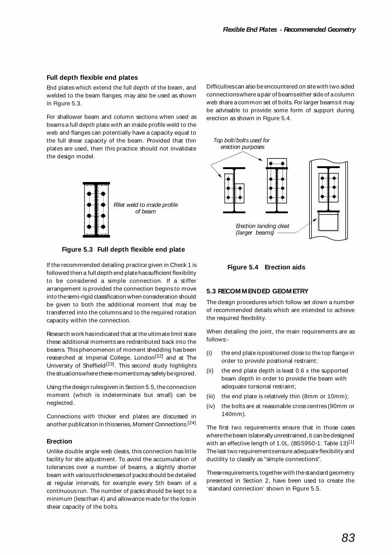
83
Full depth flexible end platesEnd plates which extend the full depth of the beam, andwelded to the beam flanges, may also be used as shownin Figure 5.3.
For shallower beam and column sections when used asbeams a full depth plate with an inside profile weld to theweb and flanges can potentially have a capacity equal tothe full shear capacity of the beam. Provided that thinplates are used, then this practice should not invalidatethe design model.
If the recommended detailing practice given in Check 1 isfollowed then a full depth end plate has sufficient flexibilityto be considered a simple connection. If a stifferarrangement is provided the connection begins to moveinto the semi-rigid classification when consideration shouldbe given to both the additional moment that may betransferred into the columns and to the required rotationcapacity within the connection.
Research work has indicated that at the ultimate limit statethese additional moments are redistributed back into thebeams. This phenomenon of moment shedding has beenresearched at Imperial College, London[22] and at TheUniversity of Sheffield[23]. This second study highlightsthe situations where these moments may safely be ignored.
Using the design rules given in Section 5.5, the connectionmoment (which is indeterminate but small) can beneglected.
Connections with thicker end plates are discussed inanother publication in this series, Moment Connections.[24]
ErectionUnlike double angle web cleats, this connection has littlefacility for site adjustment. To avoid the accumulation oftolerances over a number of beams, a slightly shorterbeam with various thicknesses of packs should be detailedat regular intervals, for example every 5th beam of acontinuous run. The number of packs should be kept to aminimum (less than 4) and allowance made for the loss inshear capacity of the bolts.
Difficulties can also be encountered on site with two sidedconnections where a pair of beams either side of a columnweb share a common set of bolts. For larger beams it maybe advisable to provide some form of support duringerection as shown in Figure 5.4.
5.3 RECOMMENDED GEOMETRY
The design procedures which follow set down a numberof recommended details which are intended to achievethe required flexibility.
When detailing the joint, the main requirements are asfollows:-
(i) the end plate is positioned close to the top flange inorder to provide positional restraint;
(ii) the end plate depth is least 0.6 x the supportedbeam depth in order to provide the beam withadequate torsional restraint;
(iii) the end plate is relatively thin (8mm or 10mm);
(iv) the bolts are at reasonable cross centres (90mm or140mm).
The first two requirements ensure that in those caseswhere the beam is laterally unrestrained, it can be designedwith an effective length of 1.0L. (BS 5950-1: Table 13)[1]
The last two requirements ensure adequate flexibility andductility to classify as "simple connections".
These requirements, together with the standard geometrypresented in Section 2, have been used to create the‘standard connection’ shown in Figure 5.5.
Figure 5.4 Erection aids
Flexible End Plates - Recommended Geometry
Figure 5.3 Full depth flexible end plate
Top bolt/bolts used for erection purposes
Erection landing cleat(larger beams)
Fillet weld to inside profileof beam

84
Flexible End Plates - Recommended Geometry
Beam-to-column Beam-to-beam
Supported Recommended Bolt
Beam End Plate Size Gauge
Bp x tp g
up to 457 150 x 8 90
533 and above 200 x 10 140
Bolts: M20 8.8 in 22mm diameter holes
End Plate: Steel grade S275, minimum length 0.6Dwhere D is depth of supported beam
Figure 5.5 Standard partial depth end plate connections
Bolt gauge, g
Flange chamferedto clear bolts
A A
Section AA
End plate thickness, t
End Plate Width, B
40
40
Holes @70 pitch
50
Supporting column
Supporting beam
Supportedbeam
Supportedbeam
Supportedbeam
ppt
p
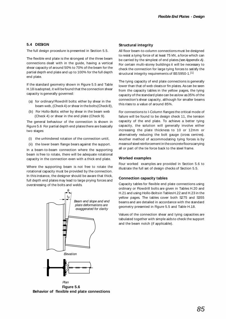
85
.
Flexible End Plates - Design
Figure 5.6Behavior of flexible end plate connections
5.4 DESIGN
The full design procedure is presented in Section 5.5.
The flexible end plate is the strongest of the three beamconnections dealt with in the guide, having a verticalshear capacity of around 50% to 70% of the beam for thepartial depth end plate and up to 100% for the full depthend plate.
If the standard geometry shown in Figure 5.5 and TableH.18 is adopted, it will be found that the connection shearcapacity is generally governed:
(a) for ordinary/Flowdrill bolts: either by shear in thebeam web, (Check 4) or shear in the bolts (Check 8),
(b) For Hollo-Bolts: either by shear in the beam web (Check 4) or shear in the end plate (Check 9).
The general behaviour of the connection is shown inFigure 5.6 For partial depth end plates there are basicallytwo stages:
(i) the unhindered rotation of the connection until,
(ii) the lower beam flange bears against the support.
In a beam-to-beam connection where the supportingbeam is free to rotate, there will be adequate rotationalcapacity in the connection even with a thick end plate.
Where the supporting beam is not free to rotate therotational capacity must be provided by the connection.In this instance, the designer should be aware that thick,full depth end plates may lead to large prying forces andoverstressing of the bolts and welds.
Structural integrityAll floor beam-to-column connections must be designedto resist a tying force of at least 75 kN, a force which canbe carried by the simplest of end plates (see Appendix A).For certain multi-storey buildings it will be necessary tocheck the connection for large tying forces to satisfy thestructural integrity requirements of BS 5950-1.[1]
The tying capacity of end plate connections is generallylower than that of web cleats or fin plates. As can be seenfrom the capacity tables in the yellow pages, the tyingcapacity of the standard plate can be as low as 35% of theconnection's shear capacity, although for smaller beamsthis rises to a value of around 85%.
For connections to I-Column flanges the critical mode offailure will be found to be design check 11, the tensioncapacity of the end plate. To achieve a better tyingcapacity, the solution will generally involve eitherincreasing the plate thickness to 10 or 12mm oralternatively reducing the bolt gauge (cross centres).Another method of accommodating tying forces is bymeans of steel reinforcement in the concrete floors carryingall or part of the tie force back to the steel frame.
Worked examplesFour worked examples are provided in Section 5.6 toillustrate the full set of design checks of Section 5.5.
Connection capacity tablesCapacity tables for flexible end plate connections usingordinary or Flowdrill bolts are given in Tables H.20 andH.21 and using Hollo-Bolts in Tables H.22 and H.23 in theyellow pages. The tables cover both S275 and S355beams and are detailed in accordance with the standardgeometry presented in Figure 5.5 and Table H.18.
Values of the connection shear and tying capacities aretabulated together with simple aids to check the supportand the beam notch (if applicable).
tp
θ
Plan
Beam end slope and endplate deformations are exaggerated for clarity
Elevation

86
Flexible End Plates - Design Procedures
5.5 DESIGN PROCEDURES
Recommended design modelAny simple equilibrium analysis is suitable for design.The one used in this publication is in accordance withtraditional UK design practice and is based on the simplysupported beam end reaction.
Check 1 Recommended detailing practice
Check 2 Supported beam – Welds
Check 3 Not applicable
Check 4 Supported beam – Capacity at the connection
Check 5 Supported beam – Capacity at a notch
Check 6 Supported beam – Local stability of notched beam
Check 7 Unrestrained supported beam – Overall stability of notched beam
Check 8 Supporting beam/column – Bolt group
Check 9 Supporting beam/column – Connecting elements
Check 10 Supporting beam/column – Local capacity
Check 11 Structural integrity – Connecting elements
Check 12 Structural integrity – Supported beam
Check 13 Structural integrity – Tension bolt group/welds
Check 14 Structural integrity – Supporting column web (UC or UB)
Check 15 Structural integrity – Supporting column wall (RHS)
Check 16 Not applicable
The design procedure applies to beams connected to thecolumn flange, the column web, the supporting beamweb or to RHS columns. Although the figures show partialdepth end plates the design procedures apply equally tofull depth end plates.
Supporting column (I or RHS)
Supported beamn rowsof bolts
Supported beam
Supporting beam
n rowsof bolts
Assumed line of shear transfer
(face of column)
Assumed line of shear transfer(face of web)Fv Fv
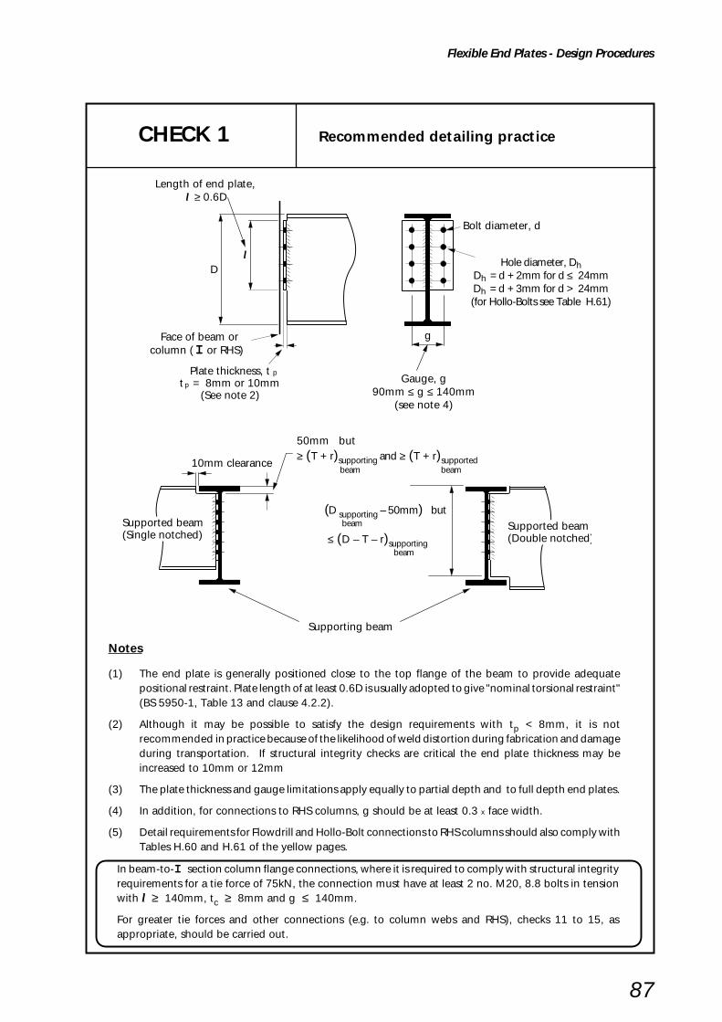
87
Flexible End Plates - Design Procedures
Hole diameter, DhDh = d + 2mm for d ≤ 24mmDh = d + 3mm for d > 24mm(for Hollo-Bolts see Table H.61)
Length of end plate, l ≥ 0.6D
CHECK 1 Recommended detailing practice
Notes
(1) The end plate is generally positioned close to the top flange of the beam to provide adequatepositional restraint. Plate length of at least 0.6D is usually adopted to give "nominal torsional restraint"(BS 5950-1, Table 13 and clause 4.2.2).
(2) Although it may be possible to satisfy the design requirements with tp < 8mm, it is notrecommended in practice because of the likelihood of weld distortion during fabrication and damageduring transportation. If structural integrity checks are critical the end plate thickness may beincreased to 10mm or 12mm
(3) The plate thickness and gauge limitations apply equally to partial depth and to full depth end plates.
(4) In addition, for connections to RHS columns, g should be at least 0.3 x face width.
(5) Detail requirements for Flowdrill and Hollo-Bolt connections to RHS columns should also comply withTables H.60 and H.61 of the yellow pages.
lD
Plate thickness, tt = 8mm or 10mm
(See note 2)
p
p
Bolt diameter, d
g
10mm clearance
Supported beam(Single notched)
Face of beam or column ( I or RHS)
Supported beam(Double notched)
Supporting beam
Gauge, g90mm ≤ g ≤ 140mm
(see note 4)
(D supporting – 50mm) but
beam
≤ (D – T – r)supporting
beam
50mm but≥ (T + r)supporting and ≥ (T + r)supported
beam beam
In beam-to-I section column flange connections, where it is required to comply with structural integrityrequirements for a tie force of 75kN, the connection must have at least 2 no. M20, 8.8 bolts in tensionwith l ≥ 140mm, tc ≥ 8mm and g ≤ 140mm.
For greater tie forces and other connections (e.g. to column webs and RHS), checks 11 to 15, asappropriate, should be carried out.

88
Flexible End Plates - Design Procedures
CHECK 2 Supported beam - Welds
Basic requirement:
Fv ≤ Pweld
Pweld = capacity of the fillet weld
= pw lwe a
pw = design strength of the weld(BS 5950-1, Table 37)
l
Critical weld
l
Critical weld Critical weld
Single notched beam Double notched beaml
Fv Fv Fv
CHECK 3 Not applicable (see Table 3.1)
Capacity of fillet welds connecting end plate to beam web
where:
lwe = total effective length of the weld to beam web(BS 5950-1, cl. 6.8.2)
= 2 (l – 2s)
a = effective throat size of the weld
= 0.7s (normally)
s = leg length of the fillet weld

89
Flexible End Plates - Design Procedures
CHECK 4 Supported beam - Capacity at connection
Shear capacity of the beam web at the end plate
Basic requirement:
Fv ≤ Pv
Pv = shear capacity of the beam
connected to the end plate
Pv = 0.6 py Av
l l l
Critical length of web for shear
Fv Fv Fv
where:
Av = 0.9 l tw
(BS 5950-1, cl. 4.2.3)
tw = thickness of beam web
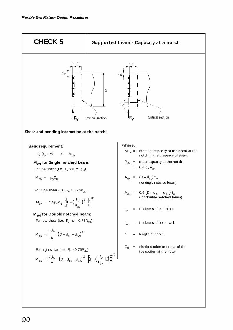
90
Flexible End Plates - Design Procedures
CHECK 5 Supported beam - Capacity at a notch
t cp
Critical section
t cp
Critical section
D
d c2
dc1 dc1
Fv Fv
Basic requirement:
Fv (tp + c) ≤ McN
McN for Single notched beam:
For low shear (i.e. Fv ≤ 0.75PvN)
McN = pyZN
For high shear (i.e. Fv > 0.75PvN)
Fv 1/2
McN = 1.5pyZN 1 – ( ___ )2
PvN
McN for Double notched beam:
For low shear (i.e. Fv ≤ 0.75PvN)
pytwMcN = ____ (D – dc1 – dc2)
2
6
For high shear (i.e. Fv > 0.75PvN)
pytw 2 Fv 2 1/2
McN = ____ (D – dc1 – dc2) 1 – (____ ) 4 PvN
Shear and bending interaction at the notch:
where:McN = moment capacity of the beam at the
notch in the presence of shear.
PvN = shear capacity at the notch
= 0.6 py AvN
AvN = (D – dc1) tw(for single notched beam)
AvN = 0.9 (D – dc1 – dc2 ) tw(for double notched beam)
tp = thickness of end plate
tw = thickness of beam web
c = length of notch
ZN = elastic section modulus of thetee section at the notch

91
Flexible End Plates - Design Procedures
D
c
D
c
c
dc1dc1
dc2
CHECK 6 Supported beam - Local stability of notched beam
When the beam is restrained against lateral torsional buckling, no account need be taken of notch stability provided the following conditions are met:
For one flange notched [14],[l5]
Basic requirement:
dc1 ≤ D/2 and:
c ≤ D for D/tw ≤ 54.3 (S275 steel)
160000Dc ≤ –––––––– for D/tw > 54.3 (S275 steel)
(D/tw)3
c ≤ D for D/tw ≤ 48.0 (S355 steel)
110000Dc ≤ –––––––– for D/tw > 48.0 (S355 steel)
(D/tw)3
For both flanges notched [15]
Basic requirement:
Max (dc1 , dc2) ≤ D/5 and:
c ≤ D for D/tw ≤ 54.3 (S275 steel)
160000Dc ≤ –––––––– for D/tw > 54.3 (S275 steel)
(D/tw)3
c ≤ D for D/tw ≤ 48.0 (S355 steel)
110000Dc ≤ –––––––– for D/tw > 48.0 (S355 steel)
(D/tw)3
where:
tw = thickness of supported beam web
Where the notch length c exceeds these limits, either suitable stiffening should be provided or the notch
should be checked to references 14, 15 and 16.
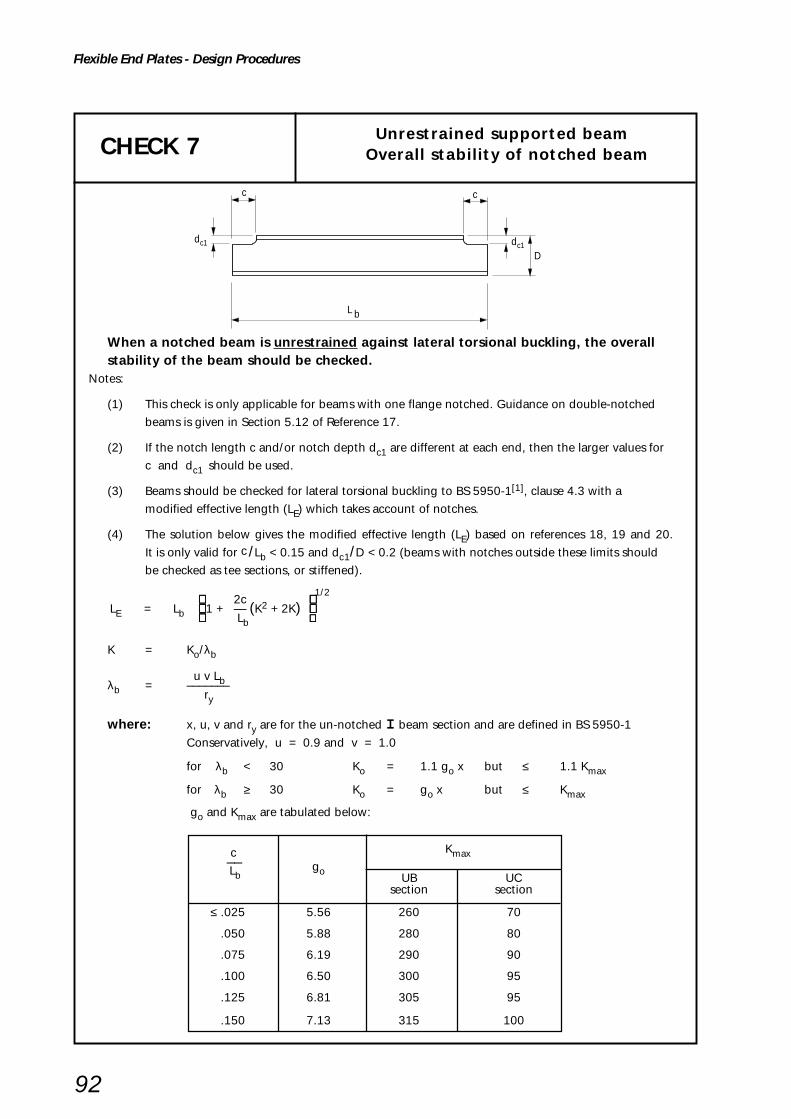
92
Flexible End Plates - Design Procedures
CHECK 7 Unrestrained supported beamOverall stability of notched beam
c
D
b
c
L
dc1dc1
When a notched beam is unrestrained against lateral torsional buckling, the overallstability of the beam should be checked.
Notes:
(1) This check is only applicable for beams with one flange notched. Guidance on double-notched
beams is given in Section 5.12 of Reference 17.
(2) If the notch length c and/or notch depth dc1 are different at each end, then the larger values for
c and dc1 should be used.
(3) Beams should be checked for lateral torsional buckling to BS 5950-1[1], clause 4.3 with a
modified effective length (LE) which takes account of notches.
(4) The solution below gives the modified effective length (LE) based on references 18, 19 and 20.
It is only valid for c /Lb < 0.15 and dc1/D < 0.2 (beams with notches outside these limits should
be checked as tee sections, or stiffened).
2c 1/2
LE = Lb 1 + –– (K2 + 2K) Lb
K = Ko/λb
u v Lbλb = ––––––– ry
where: x, u, v and ry are for the un-notched I beam section and are defined in BS 5950-1
Conservatively, u = 0.9 and v = 1.0
for λb < 30 Ko = 1.1 go x but ≤ 1.1 Kmax
for λb ≥ 30 Ko = go x but ≤ Kmax
go and Kmax are tabulated below:
c Kmax
–– goUB UC
Lb
section section
≤ .025 5.56 260 70
.050 5.88 280 80
.075 6.19 290 90
.100 6.50 300 95
.125 6.81 305 95
.150 7.13 315 100

93
Flexible End Plates - Design Procedures
CHECK 8 Supporting beam/column - Bolt group
Check these bolts in shearunder concentric load
Check these bolts in shearunder concentric load
Supporting beam
Supporting columnI or RHS
e1e1
Basic requirement:
Fv ≤ Σ Ps
Ps = shear capacity of single bolt
= ps As*
but for the top pair of bolts, Ps is the smaller of:
ps As* or 0.5 kbse1 tp pbs
Shear capacity of bolt group connecting end plate to supporting beam or column
* For Hollo-Bolts ps As should be taken as the shear capacity as given in Table H.56 of the yellow pages
where:
ps = shear strength of a bolt
As = shear area of a bolt
tp = thickness of end plate
pbs = bearing strength of end plate
e1 = end distance
kbs = 1.0 for standard clearance holes,
Flowdrill and Hollo-Bolts
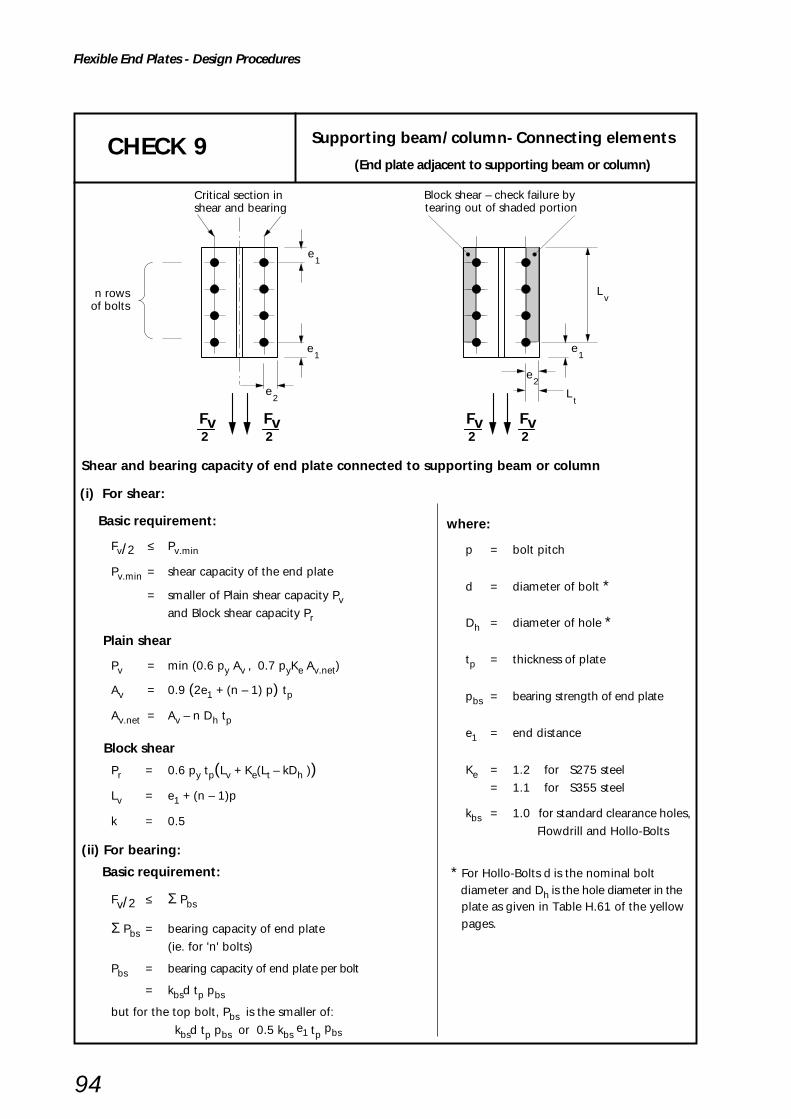
94
Flexible End Plates - Design Procedures
CHECK 9 Supporting beam/column- Connecting elements
(End plate adjacent to supporting beam or column)
Critical section in shear and bearing
Block shear – check failure by tearing out of shaded portion
e1
e1
e1
e2
n rowsof bolts
2Fv
2Fv
2Fv
2Fv
Lv
e2
Lt
Shear and bearing capacity of end plate connected to supporting beam or column
(i) For shear:
Basic requirement:
Fv/2 ≤ Pv.min
Pv.min = shear capacity of the end plate
= smaller of Plain shear capacity Pvand Block shear capacity Pr
Plain shear
Pv = min (0.6 py Av , 0.7 pyKe Av.net)
Av = 0.9 (2e1 + (n – 1) p) tp
Av.net = Av – n Dh tp
Block shear
Pr = 0.6 py tp(Lv + Ke(Lt – kDh ))
Lv = e1 + (n – 1)p
k = 0.5
(ii) For bearing:
Basic requirement:
Fv/2 ≤ Σ Pbs
Σ Pbs = bearing capacity of end plate
(ie. for 'n' bolts)
Pbs = bearing capacity of end plate per bolt
= kbsd tp pbs
but for the top bolt, Pbs is the smaller of:
kbsd tp pbs or 0.5 kbs e1 tp
pbs
where:
p = bolt pitch
d = diameter of bolt *
Dh = diameter of hole *
tp = thickness of plate
pbs = bearing strength of end plate
e1 = end distance
Ke = 1.2 for S275 steel
= 1.1 for S355 steel
kbs = 1.0 for standard clearance holes,
Flowdrill and Hollo-Bolts
* For Hollo-Bolts d is the nominal bolt diameter and Dh is the hole diameter in the
plate as given in Table H.61 of the yellowpages.

95
Flexible End Plates - Design Procedures
CHECK 10 Supporting beam/column - Local capacity(with one supported beam)
(i) For shear:
Basic requirement:
Fv/2 ≤ Pv
Pv = Iocal shear capacity of supporting beam webor I column web or RHS column wall
Pv = min (0.6 py Av , 0.7 pyKe Av.net)
Av = (et + (n – 1) p + eb) tw
Av.net = Av – n Dh tw
(ii) For bearing:
Basic requirement:
Fv––– ≤ Pbs2 n
Pbs = bearing capacity of supporting beamor column per bolt
= kbsd tw pbs
pbs = bearing strength of supporting beam or column
et1
I Column RHS Column
web thickness wtwall
thickness wt
Supporting Beam
web thickness wt
Top of column web or RHS wall
n rowsof bolts
n rowsof bolts
Critical sectionsCritical sections
eb1
g
et1
g g
Supporting Column
2Fv
2Fv
2Fv
2Fv
2Fv
2Fv
Fv Fv
Local shear and bearing capacity of supporting beam web or column web or RHS wallfor one supported beam
where:et = smaller of et1 and 5d
eb = smallest of eb1, g/2 and 5d(for supporting beam)
= smaller of g/2 and 5d(for supporting column)
p = bolt pitch
d = diameter of bolt *
Dh = diameter of hole *
tw = thickness of supportingbeam web or column webor RHS wall
Ke = 1.2 for S275 steel
= 1.1 for S355 steel
kbs = 1.0 for standard clearence holes, Flowdrill and Hollo-Bolts
* For Hollo-Bolts d is the nominal bolt diameter and Dh is the hole diameter in the RHS as given in Table H.61 of the yellow pages.
For Flowdrill the diameter of the hole is the bolt diameter.
Note: The above check (i) is for local shear only; the effects of any global shear forces must also be considered.
If the beam is connected to a rolled column flange, and the thickness of the column flange is less thanthe thickness of the cleat then the bearing capacity of the flange should also be checked.
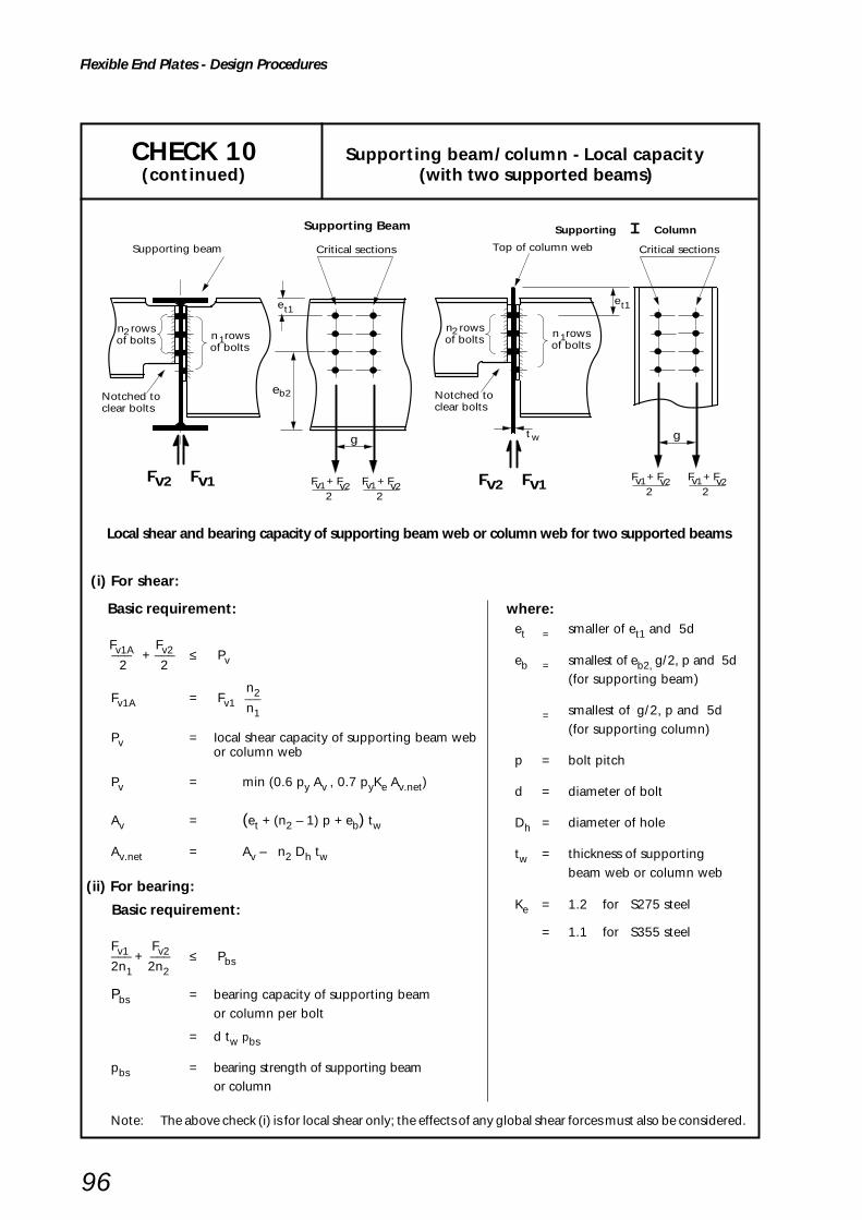
96
Flexible End Plates - Design Procedures
CHECK 10 Supporting beam/column - Local capacity (continued) (with two supported beams)
Local shear and bearing capacity of supporting beam web or column web for two supported beams
(i) For shear:
Basic requirement:
Fv1A Fv2––– + ––– ≤ Pv 2 2
n2Fv1A = Fv1 ––– n1
Pv = Iocal shear capacity of supporting beam webor column web
Pv = min (0.6 py Av , 0.7 pyKe Av.net)
Av = (et + (n2 – 1) p + eb) tw
Av.net = Av – n2 Dh tw
(ii) For bearing:
Basic requirement:
Fv1 Fv2––– + ––– ≤ Pbs2n1 2n2
Pbs = bearing capacity of supporting beamor column per bolt
= d tw pbs
pbs = bearing strength of supporting beamor column
where:et = smaller of et1 and 5d
eb = smallest of eb2, g/2, p and 5d(for supporting beam)
= smallest of g/2, p and 5d(for supporting column)
p = bolt pitch
d = diameter of bolt
Dh = diameter of hole
tw = thickness of supportingbeam web or column web
Ke = 1.2 for S275 steel
= 1.1 for S355 steel
Notched toclear bolts
wt
Notched toclear bolts
Supporting beam Critical sections
eb2
Critical sections
Supporting I ColumnSupporting Beam
Top of column web
1n rowsof bolts1n rows
of bolts
n rowsof bolts
2n rowsof bolts
2
et1et1
g g
F + Fv2v12
Fv1Fv2 F + Fv2v12
Fv1Fv2F + Fv2v1
2F + Fv2v1
2
Note: The above check (i) is for local shear only; the effects of any global shear forces must also be considered.

97
Flexible End Plates - Design Procedures
CHECK 11 Structural integrity - connecting elements
Design tensile strength
pu = Us /1.25
S275 328 N/mm2
S355 392 N/mm2
Values of Us taken fromBS EN 10025: 1993[21]
Basic requirement:Tie force ≤ Tying capacity of end plate
2(MuA + MuB)Tying capacity = –––––––––––– (see Appendix C) of end plate L
MuA = moment capacity of end plate at section AA
pu LeA tp2
= –––––––– 4
MuB = moment capacity of end plate at section BB
pu LeB tp2
= –––––––– 4
pu = design tensile strength
= Us /1.25 (see inset box)
n rowsof bolts
g
p
p
p
L
A B
A B
A B
L
c
Tie forcee1
e1
e2
1
Note: This check is only needed if it is necessary to comply with structural integrity requirements
Structural integrity – tension capacity of end plate
where:LeA = effective length of plastic hinge
at section AA
= 2eeA + (n – 1) peA
eeA = e1 but ≤ e2
peA = p but ≤ 2e2
LeB = effective length of plastichinge at section BB
= 2eeB + (n – 1) peB
eeB = e1 but ≤ c1 + Dh/2
peB = p but ≤ 2c1 + Dh
c1 = 0.5 (g – tw – 2s)
L = distance between plastic hinges
= c1 – Dh/2
tp = thickness of end plate
Dh = diameter of hole *
tw = thickness of beam web
s = leg length of the fillet weld
* For Hollo-Bolts Dh is the hole diameter in the plate as given in Table H.61 of the yellow
pages.
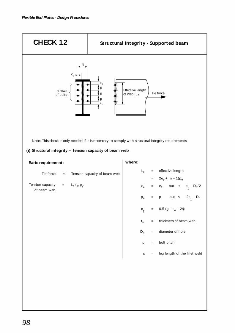
98
Flexible End Plates - Design Procedures
CHECK 12 Structural Integrity - Supported beam
Basic requirement:
Tie force ≤ Tension capacity of beam web
Tension capacity = Le tw py
of beam web
n rowsof bolts
p
p
p
g
Tie force.
Effective lengthof web, L e
e1
e1
c1
Note: This check is only needed if it is necessary to comply with structural integrity requirements
(i) Structural integrity – tension capacity of beam web
where:
Le = effective length
= 2ee + (n – 1)pe
ee = e1 but ≤ c1 + Dh/2
pe = p but ≤ 2c1 + Dh
c1
= 0.5 (g – tw – 2s)
tw = thickness of beam web
Dh = diameter of hole
p = bolt pitch
s = leg length of the fillet weld

99
Flexible End Plates - Design Procedures
CHECK 13 Structural integrity - Tension bolt group/welds
Tension bolt group
n rowsof bolts
p
p
p
Tie force
Critical weld
g
c
e1
e1
1
Basic requirement:
(i) Structural integrity – tension capacity of bolts in presence of extreme prying
Tie force ≤ Tension capacity of bolt group
Tension capacity of= 2n At ptr * bolt group
reduced tension strength of a boltptr =
in presence of extreme prying
= 300N/mm2 for 8.8 bolts(see Appendix D)
* See note 3 for Flowdrill or Hollo-Bolts
(ii) Structural integrity – weld tension capacity
Tie force ≤ Tension capacity of beamweb/end plate weld
Tension capacity of beam= 2(1.25pwa (Le– 2s))
web/end plate weld
Notes:
(1) The reduced tension strength (ptr) is only used when end plate design for structural integrity is based
on Appendix C or CHECK 11.
(2) Where a beam is attached to one side of a column web without a beam on the opposite side, or to
RHS column, the bolt tensions have to be resisted by local bending of the web or RHS wall. UC webs
can resist 75kN but need to be checked if the tying force is higher. UB webs need to be checked for
75kN and higher tying forces. CHECK 14 proposes a design model which could be used for this
purpose. CHECK 15 proposes a design model for checking the wall of RHS column.
(3) For Flowdrill or Hollo-Bolt connections the value Atptr is replaced by the Structural integrity Tensile
capacity (Psi) taken from Tables H.55b and H.56 respectively in the yellow pages.
Note: These checks are only needed if it is necessary to comply with structural integrity requirements
where:At = tensile stress area of a bolt
n = number of rows of bolts
Le = 2ee + (n – 1) pe
ee = e1 but ≤ c1 + Dh /2
pe = p but ≤ 2c1 + Dh
c1
= 0.5 (g – tw – 2s)
tw = thickness of beam web
a = effective throat size of weld
= 0.7s (normally)
s = leg length of the fillet weld
p = bolt pitch
pw = design strength of the weld(BS 5950-1, Table 37)
Dh = diameter of hole

100
Flexible End Plates - Design Procedures
CHECK 14 Structural integrity – Supporting column web (UC or UB)
Basic requirement:
Tie force ≤ Tying capacity of column web
Tying capacity 8 Mu= ––––– (η
1 + 1.5(1 – β1)0.5 (1 – γ1)0.5) *of column web 1 – β 1
Mu = moment capacity of column
web per unit length
pu tw2
= –––––– 4
pu = design tensile strength of the column
= Us /1.25 (see inset box)
* Factor 1.5 in the equation includes an allowance for
the axial compression in the column.Design tensile strength
pu = Us /1.25
S275 328 N/mm2
S355 392 N/mm2
Values of Us taken from BS EN 10025: 1993[21]
Note: This check is only needed if it is necessary to comply with structural integrity requirements
Structural integrity – Tying capacity of rolled column web in the presence of axial compression inthe column
where:
(n-1) p – n
Dh 2η1 = –––––––––––––
dc gβ1 = –––
dc
Dhγ1 = –––
dc
d c = depth of column between fillets
tw = thickness of column web
g = gauge (cross centres)
Dh = diameter of hole
Note: The check is required for either single-sided connections to the rolled column webor unequally loaded double-sided connections to the rolled column web.
Tie Force
End plateconnecting to column web
(n-1)p
bolt holes deducted
yield lines
p t w
dc
g

101
Flexible End Plates - Design Procedures
CHECK 15 Structural integrity –Supporting column wall (RHS)
Tie Force
g
1.5t w
t w
B
End plate connecting to RHS column
p (n-1)p
bolt holes deducted
yield lines
Note: This check is only needed if it is necessary to comply with structural integrity requirements
Structural integrity – Tying capacity of RHS wall in the presence of axial compression in thecolumn
Basic requirement:
Tie force ≤ Tying capacity of RHS column wall
Tying capacity 8 Mu= ––––– (η
1 + 1.5(1 – β1)0.5 (1 – γ1)0.5) * RHS column wall 1 – β 1
Mu = moment capacity of RHS column
wall per unit length
pu tw2
= –––––– 4
pu = design tensile strength of the RHS column
= Us /1.25 (see inset box)
* Factor 1.5 in the equation includes an allowance
for the axial compression in the column.
Design tensile strength
pu = Us /1.25
S275 328 N/mm2
S355 392 N/mm2
Values of Us taken fromBS EN 10210-1: 1994[3]
where:
(n-1) p – n
Dh 2η1 = –––––––––––––––
(B – 3tw) g
β1 = ––––––––– (B – 3tw)
Dhγ1 = –––––––––
(B – 3tw)
B = overall width of RHS column wallto which the connection is made
tw = thickness of RHS column
Dh = diameter of hole in RHS
= bolt diameterfor Flowdrill
= hole diameter (in RHS) given inTable H.61 of yellow pages forHollo-Bolt
g = gauge (cross centres)
n = number of rows of bolts
p = bolt pitch

Flexible End Plate - Worked Examples
5.6 WORKED EXAMPLES
The worked examples show design calculations for typicalstandard connections. Each example demonstrates firstthe use of the capacity tables (yellow pages) and then fullchecks according to the procedures in Section 5.5. The fullchecks will normally only need to be applied to non-standard connections but their application to standardconnections demonstrates the validity of the much simplerprocess when using standard details.
When calculations must be made for non-standardconnections some design checks may be omitted where itis obvious, from inspection of the detail, that a check is notcritical. In the case of Example 1, Check 3 and Check 9Block Shear calculation are not made since they are nevera critical factor for end plates with bolts spaced at reasonablecentres in the plate length. However, if a connectiondesign was made using a long plate with bolts concentratedat one end, it is possible that Block Shear failure could occurbefore Plain Shear failure and then the Block shear checksshould be made.
Check 7, dealing with overall stability of an unrestrainedbeam, should be undertaken by the member designertaking account of any notching required at the ends of thesupported beam in order to facilitate the use of a simpleconnection.
Checks 11 to 15 deal with structural integrity in thepresence of an axial tie force required to be developed insome members to ensure the steel frame is sufficientlyrobust, or in the case of some multi-storey buildings, tolocalise accidental damage. When tying capacity is notrequired these checks may be omitted.
Example 1
Example 1 covers design checks for a two sided beam-to-beam connection. A 200 x 10 end plate is used for bothbeams since it is necessary to have common bolt centresin the supporting beam.
Example 2
Example 2 demonstrates the additional design checksrequired when a beam-to-column web connection mustbe designed to resist tying forces.
Example 3
Example 3 is a beam connection to an RHS column usingnormal grade 8.8 bolts in Flowdrill threaded holes toconnect a flexible end plate to the column wall. The beamsizes and vertical reactions as in Example 1, so onlychecks which are different to those in the first example areshown. A 150 x 8 end plate is used for the smaller beamand a 200 x 10 for the larger beam since the connectingbolts to the column are not common to both beams.
The connection design also considers tie forces in thebeams but it should be noted that the tie forces areignored in checks for vertical reactions and vertical reactionsare ignored in checks for tie forces.
Example 4
Example 4 covers the same beam for connections to anRHS column as in Example 3 but uses Hollo-Bolts toconnect a flexible end plate to the column wall. However,Hollo-Bolts require larger than normal holes so differentstandard details (see Table H.3) have to be used tomaintain an adequate edge distance from the hole lines.
102

Flexible End Plates - Worked Example 1
103
Title Example 1 - Flexible End Plates - Beam to Beam Sheet
BCSA
CALCULATIONSHEET
Calcs by
Title
Client
Checked by Date
Job No Sheet Joints in Steel Construction - Simple Connections
Example 1 - Flexible End Plates - Beam to Beam
SCI/BCSA Connections Group
RS AM May 2002
1 of 12
140
Flange chamferedto clear bolts
50 Notch
40
70
70
70
7040
40
70
N = 120
533 x 210 x 92 UBGrade S275
406 x 178 x 74 UBGrade S275
610 x 229 x 140 UBGrade S275
6
Note: Bolt gauge set to accommodate the larger beam
550 kN400 kN
See Figure 5.5and
Yellow pagesTable H.3
Flexible End Plates: 200 x 10 200 x 10(Type EB4) (Type EB6)
Design Information:
Bolts: M20 8.8Welds: 6mm fillet
Material: All S275
Note: End plate size and details are governed by the larger beam, hence the end plate for thesmaller beam is 200 x 10 and not 150 x 8 as recommended in Figure 5.5
DESIGN EXAMPLE 1
Check the following beam to beam connection for the design forces shown. Yellow pages used for initial selection of End plates.
See Figure 5.5and Note below

Flexible End Plates- Worked Example 1
104
Title Example 1 - Flexible End Plates - Beam to Beam Sheet2 of 12
Flange chamferedto clear bolts
40
533 x 210 x 92 UBGrade S275
406 x 178 x 74 UBGrade S275
610 x 229 x 140 UBGrade S275
550 kN400 kN
CONNECTION DESIGN USING CAPACITY TABLES FROM YELLOW PAGES
406 x 178 x 74 UB Grade S275 533 x 210 x 92 UB Grade S275
End plate type EB4(200 x 10) End plate type EB6 (200 x 10)
Note: End plate size is determined by the sizeof the opposing beam.
Welds 6mm fillet Welds 6mm fillet
Bolts M20 8.8 Bolts M20 8.8
Bolts at 140 cross centres Bolts at 140 cross centres
4 rows of bolts 6 rows of bolts
From Capacity tables in yellow pages From Capacity table H.20 in yellow pages
The values obtained from the capacity TableH.20 are for a 150 x 8 end plate (type EA4)
Connection shear capacity Connection shear capacity= 409kN > 400kN = 645kN > 550kN ∴∴∴∴∴ O.K.
Maximum notch length Maximum notch length= 218mm > 120mm = 229mm > 120mm ∴∴∴∴∴ O.K.
Web thickness of supporting beam = 13.1mm Table H.64
Minimum support thickness = (5.6 + 5.8) = 11.4mm < 13.1mm ∴∴∴∴∴ O.K.
Connection is adequate
Yellow PagesTable H.20
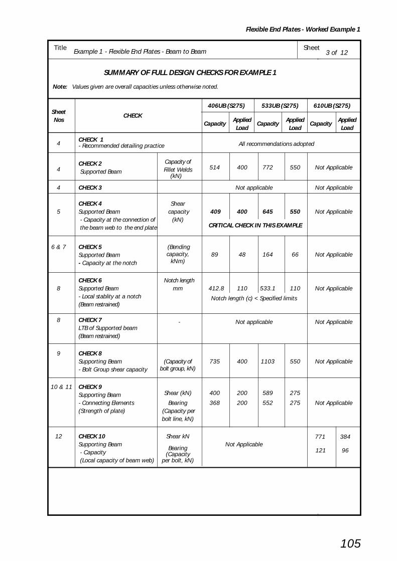
Flexible End Plates - Worked Example 1
105
Title Example 1 - Flexible End Plates - Beam to Beam Sheet3 of 12
SUMMARY OF FULL DESIGN CHECKS FOR EXAMPLE 1
Note: Values given are overall capacities unless otherwise noted.
406UB (S275) 533UB (S275) 610UB (S275)Sheet
CHECKNos
CapacityApplied
CapacityApplied
CapacityApplied
Load Load Load
4CHECK 1- Recommended detailing practice
All recommendations adopted
4CHECK 2 Capacity of
514 400 772 550 Not Applicable Supported Beam Fillet Welds
(kN)
4 CHECK 3 Not applicable Not Applicable
CHECK 4 Shear5 Supported Beam capacity 409 400 645 550 Not Applicable
- Capacity at the connection of (kN) CRITICAL CHECK IN THIS EXAMPLE the beam web to the end plate
6 & 7 CHECK 5 (Bending89 48 164 66 Not ApplicableSupported Beam capacity,
- Capacity at the notch kNm)
CHECK 6 Notch length8 Supported Beam mm 412.8 110 533.1 110 Not Applicable
- Local stablity at a notch Notch length (c) < Specified limits(Beam restrained)
8 CHECK 7 - Not applicable Not ApplicableLTB of Supported beam(Beam restrained)
9 CHECK 8Supporting Beam (Capacity of 735 400 1103 550 Not Applicable- Bolt Group shear capacity bolt group, kN)
10 & 11 CHECK 9Supporting Beam Shear (kN) 400 200 589 275
- Connecting Elements Bearing 368 200 552 275 Not Applicable(Strength of plate) (Capacity per
bolt line, kN)
12 CHECK 10 Shear kNSupporting Beam
Bearing Not Applicable
771 384
- Capacity (Capacity121 96
(Local capacity of beam web) per bolt, kN)

Flexible End Plates- Worked Example 1
106
Title Example 1 - Flexible End Plates - Beam to Beam Sheet4 of 12
CHECK 1: Recommended detailing practice
End Plates: 200 x 10mm thick
Length, l = 290mm (>0.6D for 406 UB)
= 430mm (>0.6D for 533 UB)
Bolts: 20mm dia at 140mm cross centres
CHECK 2: Supported Beam - Welds
Capacity of Fillet Welds to connecting end plate to beam web
Basic requirement: Fv ≤ Pweld
For 406 x 178 x 74 UB Grade S275
Capacity of fillet weld, Pweld = pw lwe a
Total effective length of weld, lwe = 2 ( l – 2s)= 2 (290 – (2 x 6)) = 556mm
For 6mm fillet welds, classification 35, S275 steel
pw = 220N/mm2
Throat size, a = 0.7 s = 0.7 x 6 = 4.2mm
220 x 556 x 4.2∴ Pweld = ––––––––––––––103
= 514kN
Fv = 400kN < 514kN ∴∴∴∴∴ O.K.
For 533 x 210 x 92 UB Grade S275
Capacity of fillet weld, Pweld = pw lwe a
Total effective length of weld, lwe = 2 (l – 2s)= 2 ((430 – (2 x 6) ) = 836mm
For 6mm fiillet welds, classification 35, S275 steel
pw = 220N/mm 2
Throat size, a = 0.7 s = 0.7 x 6 = 4.2mm
220 x 836 x 4.2∴ Pweld = ––––––––––––– 103
= 772kN
Fv = 550kN < 772kN ∴∴∴∴∴ O.K.
CHECK 3: Not applicable
pw fromBS 5950-1Table 37
pw fromBS 5950-1Table 37

Flexible End Plates - Worked Example 1
107
Title Example 1 - Flexible End Plates - Beam to Beam Sheet5 of 12
400 kN
l = 290
CHECK 4: Supported Beam - Capacity at connection
Shear capacity of beam web at the end plate
Basic requirement: Fv ≤ Pv
Shear capacity of beam web, Pv = 0.6 py A v
For 406 x 178 x 74 UB Grade S275
Shear area of beam web, Av = 0.9 x 290 x 9.5
= 2480mm2
Shear capacity of beam web,
0.6 x 275 x 2480Pv = ––––––––––––––
103
= 409kN
Fv = 400kN < 409kN ∴ ∴ ∴ ∴ ∴ O.K.
For 533 x 210 x 92 UB Grade S275
Shear area of beam web,
Av = 0.9 x 430 x 10.1
= 3909mm 2
Shear capacity of beam web,
0.6 x 275 x 3909Pv = ––––––––––––––
103
= 645kN
Fv = 550kN < 645kN ∴ ∴ ∴ ∴ ∴ O.K.
550 kN
l = 430

Flexible End Plates- Worked Example 1
108
Title Example 1 - Flexible End Plates - Beam to Beam Sheet6 of 12
CHECK 5: Supported Beam - Capacity at the notch
Shear and bending interaction at the notch
Basic requirement for bending: Fv (tp + c) ≤ McN
For 406 x 178 x 74 UB Grade S275
For low shear conditions:
Fv ≤ 0.75PvN and McN = py ZN
PvN = 0.6 py AvN
AvN = 363 x 9.5 = 3449mm2
0.6 x 275 x 3449PvN = ––––––––––––––– = 569kN
103
0.75PvN = 0.75 x 569 = 427kN
Fv = 400kN < 427kN ∴ ∴ ∴ ∴ ∴ Low shear criteria for bending applies
and McN = py ZN
Taking moments of area about bottom flange:
(179.5 x 16 x 8) + (347 x 9.5 x 189) = ((179.5 x 16) + (347 x 9.5)) x y
y = 105mm
Second moment of area about neutral axis: 1 179.5 x 163
Ixx = –– ( ––––––––– + (179.5 x 16 x 972))104 12
1 9.5 x 3473 + ––– ( –––––––– + (347 x 9.5 x 84.52) )
104 12
= 8370cm4
Ixx 8370ZN = ––– = ––––– = 324cm3
ymax 25.8
Moment capacity of the beam at the notch in the presence of shear McN = py ZN
275 x 324 = –––––––– = 89.1 kNm
103
Eccentric moment 400 x 120 Fv(tp + c ) = –––––––– = 48kNm
103
48kNm < 89.1kNm ∴ ∴ ∴ ∴ ∴ O.K.
12050
363
179.5 16
y
258
105
9.5
Criticalsection
t + c = N p
F =400 kN
v

Flexible End Plates - Worked Example 1
109
Title Example 1 - Flexible End Plates - Beam to Beam Sheet 7 of 12
For 533 x 210 x 92 UB Grade S275
For low shear conditions:Fv ≤ 0.75PvN and McN = py ZN
PvN = 0.6 py AvN
AvN = (D – dc1 ) tw= 483 x 10.1 = 4878mm2
0.6 x 275 x 4878∴∴∴∴∴ PvN = ––––––––––––––– = 805kN103
0.75PvN = 0.75 x 805 = 604kN
Fv = 550kN ≤ 604kN ∴ ∴ ∴ ∴ ∴ Low shear criteria for bending applies
and McN = py ZN
Taking moments of area about bottom flange:
(209.3 x 15.6 x 7.8) + (467.4 x 10.1 x 249.3) = ((209.3 x 15.6) + (467.4 x 10.1)) x y
y = 151mm
Second moment of area about neutral axis:
1 209.3 x 15.63 Ixx = ––– (––––––––––– + (209.3 x 15.6 x143.22))104 12
1 10.1 x 467.43 + ––– ( –––––––––– + (467.4 x 10.1 x 98.32))104 12
= 19858cm4
I xx 19858 ZN = ––– = –––––– = 598cm3
ymax 33.2
Moment capacity of the beam at the notch in the presence of shear McN = py ZN
275 x 598 = –––––––– = 164 kNm
103
Eccentric moment 550 x 120 Fv(tp + c ) = –––––––– = 66kNm
103
66kNm < 164kNm ∴ ∴ ∴ ∴ ∴ O.K.
F =550 kN
12050
483
209.3 15.6
y
332
151
10.1
Criticalsection
t + c = N p
v

Flexible End Plates- Worked Example 1
110
Title Example 1 - Flexible End Plates - Beam to Beam Sheet8 of 11
CHECK 6: Supported Beam - Local Stablity of notched beamWhen the beam is restrained against lateral torsional buckling no account
need be taken of notch stability provided that:
For one flange notched beam in S275 steel
Basic requirements:D
Notch depth dc1 ≤≤≤≤≤ ––2
Dand c ≤≤≤≤≤ D for –– ≤≤≤≤≤ 54.3
tw160000D D
c ≤≤≤≤≤ ––––––––– for –– > 54.3( D/tw )3 t w
For 406 x 178 x 74 UB Grade S275 (c = 110mm)
412.8Notch depth dc1 = 50mm < ––––– = 206.4mm ∴∴∴∴∴ O.K.
2
D 412.8–– = ––––– = 43.5 < 54.3 tw 9.5
c = 110mm < 412.8mm ∴∴∴∴∴ O.K.
For 533 x 210 x 92 UB (c =110 mm)
533.1Notch depth dc1 = 50mm < –––––– = 266.6mm ∴ ∴ ∴ ∴ ∴ O.K..
2
D 533.1–– = ––––– = 52.8 < 54.3 tw 10.1
c = 110mm < 533.1mm ∴∴∴∴∴ O.K.
CHECK 7: Not applicable (because the supported beam is being considered as restrained against lateral torsional buckling)
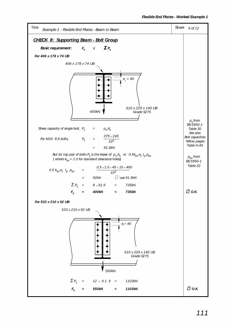
Flexible End Plates - Worked Example 1
111
Title Example 1 - Flexible End Plates - Beam to Beam Sheet 9 of 12
400kN610 x 229 x 140 UB
Grade S275
e = 40
406 x 178 x 74 UB
1
CHECK 8: Supporting Beam - Bolt Group
Basic requirement: Fv ≤ Σ Σ Σ Σ Σ Ps
For 406 x 178 x 74 UB
Shear capacity of single bolt, Ps = ps.As
375 x 245 For M20 8.8 bolts, Ps = –––––––––
103
= 91.9kN
But for top pair of bolts Ps is the lesser of ps As or 0.5kbs e1 tp pbs
( where kbs = 1.0 for standard clearance holes)
0.5 x 1.0 x 40 x 10 x 4600.5 kbs e1 tp pbs = –––––––––––––––––––
103
= 92kN ∴ use 91.9kN
Σ Ps = 8 x 91.9 = 735kN
Fv = 400kN < 735kN ∴ ∴ ∴ ∴ ∴ O.K.
For 533 x 210 x 92 UB
Σ Ps = 12 x 9 1. 9 = 1103kN
Fv = 550kN < 1103kN ∴∴∴∴∴ O.K.
pbs fromBS 5950-1Table 32
ps fromBS 5950-1Table 30See also
Bolt capacitiesYellow pagesTable H.49
e = 40
533 x 210 x 92 UB
550kN
1
610 x 229 x 140 UBGrade S275
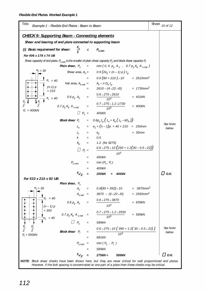
Flexible End Plates- Worked Example 1
112
Title Example 1 - Flexible End Plates - Beam to Beam Sheet 10 of 12
CHECK 9: Supporting Beam - Connecting elements Shear and bearing of end plate connected to supporting beam
Fv(i) Basic requiremenf for shear: –– ≤ Pv.min2 For 406 x 178 x 74 UB
Shear capacity of end plate, Pv.min is the smaller of plain shear capacity Pv and block shear capacity Pr
Plain shear, Pv = min ( 0. 6 py A v , 0.7 py Ke A v.net )
Shear area, Av = 0.9 (2e1 + (n – 1) p ) tp
= 0.9 (80 + 210 ) x 10 = 2610mm2
Net area, Av.net = Av – n Dh tp= 2610 – (4 x 22 x l0) = 1730mm2
0.6 x 275 x 26100.6 py Av = ––––––––––––––– = 431kN
103
0.7 x 275 x 1.2 x17300.7 py Ke A v.net = –––––––––––––––––– = 400kN
103
∴ Pv = 400kN
Block shear Pr = 0.6py tp ( Lv + Ke ( Lt – kDh ))Lv = e1 + (n – 1)p = 40 + 210 = 250mm
Lt = e2 = 30mm
k = 0.5
Ke = 1.2 (for S275)
0.6 x 275 x 10 (250 + 1.2(30 – 0.5 x 22))∴ Pr = ––––––––––––––––––––––––––––––––––––103
= 450kN
Pv.min = min (Pv , Pr )
= 400kNFv/2 = 200kN < 400kN ∴ ∴ ∴ ∴ ∴ O.K.
For 533 x 210 x 92 UB Plain shear, Pv
Av = 0.9(80 + 350) x 10 = 3870mm2
Av.net = 3870 – (6 x 22 x l0) = 2550mm2
0.6 x 275 x 38700.6 py Av = ––––––––––––––– = 639kN
103
0.7 x 275 x 1.2 x 2550 0.7 py Ke A v.net = –––––––––––––––––– = 589kN
103
∴ Pv = 589kN
0.6 x 275 x 10 ( 390 + 1.2( 30 – 0.5 x 22) ) Block shear Pr = ––––––––––––––––––––––––––––––––––––––
103
= 681kN
Pv.min = min ( Pv , Pr )
= 589kN
Fv/2 = 275kN < 589kN ∴ ∴ ∴ ∴ ∴ O.K.
NOTE: Block shear checks have been shown here, but they are never critical for well proportioned end plates.However, if the bolt spacing is concentrated at one part of a plate then these checks may be critical.
2
F = 400kN
2
e
e
(n-1) p= 210
= 40
= 40Fv Fv
v
1
1
= 302e
= 40
= 40
= 350(n – 1) p
e
F
e
F–2 2
–
F = 550kN
v v
v
1
1
= 302e
See Notebelow
See Notebelow

Flexible End Plates - Worked Example 1
113
Title Example 1 - Flexible End Plates - Beam to Beam Sheet11 of 12
pbs fromBS 5950-1Table 32
Fv(ii) Basic requirement for bearing: –– ≤ ΣΣΣΣΣ Pbs2 For 406 x 178 x 74 UB
Bearing capacity, Pbs = kbsd tp pbs
but for top bolt Pbs = min ( kbsd tp pbs , 0.5kbs e1 tp pbs )
1.0 x 20 x 10 x 460kbsd tp pbs = ––––––––––––––– = 92kN
103
1.0 x 20 x 10 x 4600.5kbse1 tp pbs = ––––––––––––––– = 92kN
103
Σ Pbs = 3 x 92 + 92 = 368kN
Fv 400–– = –––– = 200kN < 368kN ∴ ∴ ∴ ∴ ∴ O.K. 2 2
For 533 x 210 x 92 UB
Bearing capacity as above
Σ Pbs = 5 x 92 + 92 = 552kN
Fv 550–– = –––– = 275kN < 552kN ∴∴∴∴∴ O.K.2 2
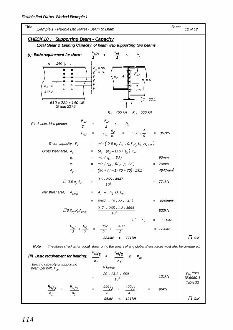
Flexible End Plates- Worked Example 1
114
Title Example 1 - Flexible End Plates - Beam to Beam Sheet12 of 12
= 550 kN = 400 kN
e = 90 tp = 70pppp
n = 421A
1B
1 2
T = 22.1
n = 61
e =
317.2 b2
610 x 229 x 140 UBGrade S275
1
Fv
Fv
Fv Fv
g = 140
CHECK 10 : Supporting Beam - CapacityLocal Shear & Bearing Capacity of beam web supporting two beams
Fv1A Fv2(i) Basic requirement for shear: ––– + ––– ≤ Pv2 2
Fv1A Fv2For double sided portion, ––– + ––– ≤ Pv 2 2
n2 4Fv1A = Fv1 –– = 550 x –– = 367kN n1 6
Shear capacity, Pv = min ( 0.6 py Av , 0.7 py Ke Av.net )
Gross shear area, Av = (et + (n2 – 1) p + eb ) twet = min ( et1 , 5d ) = 90mm
eb = min ( eb2 , g/2, p, 5d ) = 70mm
Av = (90 + (4 – 1) 70 + 70) x 13.1 = 4847mm2
0.6 x 265 x 4847 ∴ 0.6 py Av = –––––––––––––––– = 771kN
103
Net shear area, Av.net = Av – n2 Dh tw
= 4847 – (4 x 22 x 13.1) = 3694mm2
0. 7 x 265 x 1.2 x 3694 ∴0.7py Ke Av.net = ––––––––––––––––––––– = 822kN 103
∴ Pv = 771kN
Fv1A Fv2 367 400––– + ––– = –––– + –––– = 384kN 2 2 2 2
384kN < 771kN ∴∴∴∴∴ O.K
Note: The above check is for local shear only; the effects of any global shear forces must also be considered.
Fv1/2Fv2/2(ii) Basic requirement for bearing: –––– + ––––– ≤ Pbs
n1 n2
Bearing capacity of supporting
= d tw pbsbeam per bolt, Pbs
20 x 13.1 x 460= ––––––––––––––––– = 121kN
103
Fv1/2Fv2/2
550/2400/2–––– + ––––– = ––––– + ––––– = 96kN
n1 n2
6 4
96kN < 121kN ∴∴∴∴∴ O.K
pbs fromBS 5950-1Table 32

Example 2 - Flexible end plate - Beam to UC Web - Structural Integrity SheetTitle
Flexible End Plates - Worked Example 2
115
BCSA
CALCULATIONSHEET
Calcs by
Title
Client
Checked by Date
Job No SheetJoints in Steel Construction - Simple Connections
Example 2 - Flexible end plate - Beam to UC column web - Structural Integrity
SCI/BCSA Connections Group
RS AM May 2002
1 of 8
6
90 cross centres
504070
70
7040
175 kN Tie force
Supporting column305 x 305 x 137 UC
Grade S275
Supported beam406 x 178 x 74 UB
Grade S275
DESIGN EXAMPLE 2
Check the following beam to column connection for the tie force shown.
Design Information:
Bolts: M20 8.8 @ 90 c/cEnd Plates: 150 x 8 (Type EA4)
Welds: 6mm filletMaterial: All S275 steel
See figure 5.5and
Yellow pagesTable H.3
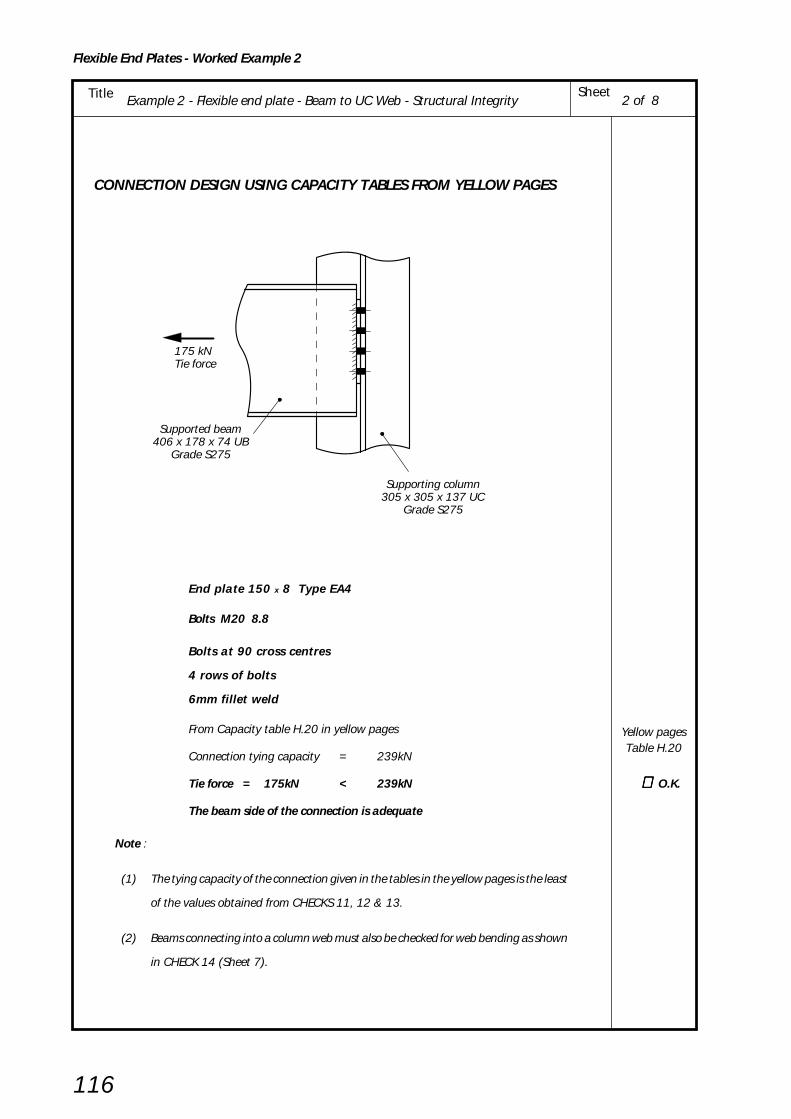
Example 2 - Flexible end plate - Beam to UC Web - Structural IntegritySheetTitle
Flexible End Plates - Worked Example 2
116
CONNECTION DESIGN USING CAPACITY TABLES FROM YELLOW PAGES
End plate 150 x 8 Type EA4
Bolts M20 8.8
Bolts at 90 cross centres
4 rows of bolts
6mm fillet weld
From Capacity table H.20 in yellow pages
Connection tying capacity = 239kN
Tie force = 175kN < 239kN ∴∴∴∴∴ O.K.
The beam side of the connection is adequate
Note :
(1) The tying capacity of the connection given in the tables in the yellow pages is the least
of the values obtained from CHECKS 11, 12 & 13.
(2) Beams connecting into a column web must also be checked for web bending as shown
in CHECK 14 (Sheet 7).
2 of 8
175 kN Tie force
Supporting column305 x 305 x 137 UC
Grade S275
Supported beam406 x 178 x 74 UB
Grade S275
Yellow pagesTable H.20

Example 2 - Flexible end plate - Beam to UC Web - Structural Integrity SheetTitle
Flexible End Plates - Worked Example 2
117
SUMMARY OF FULL DESIGN CHECKS FOR EXAMPLE 2
3 of 8
406UB 305UCS275 S275
SheetCHECK
Nos Capacity
AppliedCapacity
Applied Load Load
4 CHECK 11Structural Integrity- Connecting Elements 239 175 Not Applicable
Tension capacity of end plate (kN) CRITICAL CHECK BEAM SIDE
5 CHECK 12Structural Integrity - Supported Beam 758 175 Not ApplicableTension capacity of beam web (kN)
6 CHECK 13Structural IntegrityBolts - Tension capacity of bolt group (kN) 588 175 Not Applicable
Structural IntegrityWelds - Weld tension capacity (kN) 642 175 Not Applicable
7 & 8 CHECK 14Structural Integrity- Tying capacity of column web (kN) Not Applicable 356 175
CRITICAL CHECK COLUMN SIDE

Example 2 - Flexible end plate - Beam to UC Web - Structural IntegritySheetTitle
Flexible End Plates - Worked Example 2
118
CHECK 11 : Structural Integrity - Connecting Elements
Tension Capacity of End Plate
Basic requirement: Tie Force ≤ Tying capacity of end plate
s = fillet size
= 6 mm
tw = web thickness
= 9.5mm
1c1 = –– ( g – tw – 2s ) 2
1
= –– ( 90 – 9.5 – 2 x 6 ) 2
= 34.3mm
2 (MuA + MuB) Tying capacity of end plate = –––––––––––––
L
pu LeA tp2
Moment capacity of end plate MuA = ––––––––––– at section AA 4
pu = design tensile strength = 328N/mm2 (for S275)
tp = plate thickness = 8mm
LeA = eff. length of plastic hinge at section AA
= 2eeA + (n – 1)peA
eeA = e1 but < e2 = 30mm
peA = p but ≤ 2e2 = 60mm
∴ LeA = (2 x 30) + (4 – 1)60 = 240mm
328 x 240 x 82∴ MuA = ––––––––––––– = 1260kNmm
4 x 10³
Moment capacity of end plate MuBpu LeB tp
2= ––––––––––
at section BB 4
LeB = eff. length of plastic hinge at section BB
= 2eeB + (n – l)peBeeB = e1 but ≤ c1 + Dh/2 = 40mm
peB = p but ≤ 2c1 + Dh = 70mm
∴ LeB = (2 x 40) + (4 –1)70 = 290mm
328 x 290 x 82∴ MuB = ––––––––––––– = 1522kNmm
4 x 10³
L = distance between plastic hinges = c1 – (Dh/2)
= 34.3 – (22/2) = 23.3mm
2(MuA + MuB) 2(1260 + 1522)–––––––––––– = ––––––––––––––– = 239kN
L 23.3
Tie force = 175kN < 239kN ∴∴∴∴∴ O.K.
4 of 8
g = 90
e = 401
p = 70
n rows
e = 40p
A B
A B
e = 30
L = 23.3
A B
c = 34.3
2
175kN
1

Example 2 - Flexible end plate - Beam to UC Web - Structural Integrity SheetTitle
Flexible End Plates - Worked Example 2
119
CHECK 12: Structural Integrity - Supported Beam
(i) Tension Capacity of Beam Web
Basic requirement: Tie force ≤ Tension capacity of beam web
1c1 = –– (g – tw – 2s)
2
s = fillet size (leg length) = 6mm
tw = web thickness = 9.5mm
Tension capacity of beam web = Le tw py
Effective length, Le = 2ee + (n – 1) pe
ee = e1 but ≤ c1 + Dh /2
= 40mm
pe = p but ≤ 2c1 + Dh
= 70mm
L e = (2 x 40) + (4 – 1) 70
= 290mm
290 x 9.5 x 275∴ Le tw py = ––––––––––––– = 758kN 103
Tie force = 175kN < 758kN ∴∴∴∴∴ O.K.
5 of 8
g = 90
e = 401
p = 70
n rows
e = 401
c = 34.3
e
Criticallengthof web,
L
175 kN
1
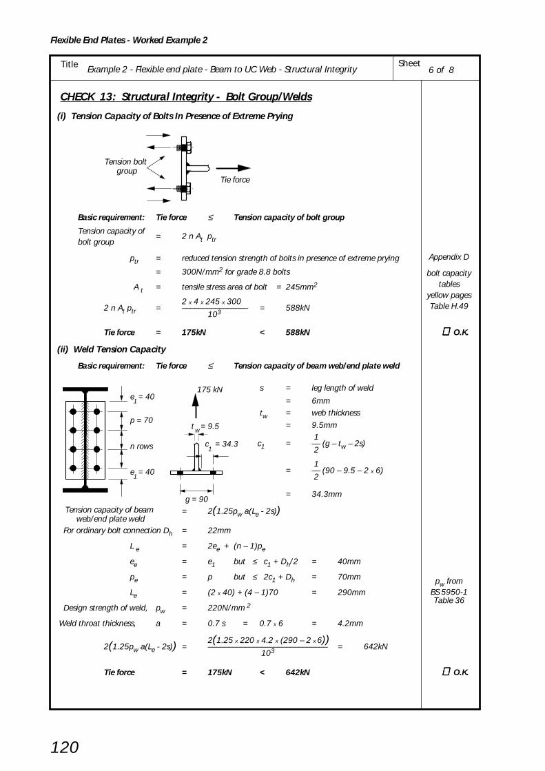
Example 2 - Flexible end plate - Beam to UC Web - Structural IntegritySheetTitle
Flexible End Plates - Worked Example 2
120
CHECK 13: Structural Integrity - Bolt Group/Welds
(i) Tension Capacity of Bolts In Presence of Extreme Prying
Basic requirement: Tie force ≤ Tension capacity of bolt group
Tension capacity of= 2 n At ptrbolt group
ptr = reduced tension strength of bolts in presence of extreme prying
= 300N/mm2 for grade 8.8 bolts
A t = tensile stress area of bolt = 245mm2
2 x 4 x 245 x 3002 n At ptr = –––––––––––––––– = 588kN
103
Tie force = 175kN < 588kN ∴∴∴∴∴ O.K.
(ii) Weld Tension Capacity
Basic requirement: Tie force ≤ Tension capacity of beam web/end plate weld
s = leg length of weld
= 6mmtw = web thickness
= 9.5mm
1 c1 = –– (g – tw – 2s) 2
1= –– (90 – 9.5 – 2 x 6) 2
= 34.3mm
Tension capacity of beam web/end plate weld
= 2(1.25pw a(Le - 2s))
For ordinary bolt connection Dh = 22mm
L e = 2ee + (n – 1)pe
ee = e1 but ≤ c1 + Dh/2 = 40mm
pe = p but ≤ 2c1 + Dh = 70mm
Le = (2 x 40) + (4 – 1)70 = 290mm
Design strength of weld, pw = 220N/mm 2
Weld throat thickness, a = 0.7 s = 0.7 x 6 = 4.2mm
2(1.25 x 220 x 4.2 x (290 – 2 x 6))2(1.25pw a(Le - 2s)) = ––––––––––––––––––––––––––––– = 642kN
103
Tie force = 175kN < 642kN ∴∴∴∴∴ O.K.
6 of 8
Tie force
Tension bolt group
g = 90
e = 401
p = 70
n rows
e = 401
c = 34.3
175 kN
t = 9.5w
1
Appendix D
bolt capacitytables
yellow pagesTable H.49
pw fromBS 5950-1Table 36
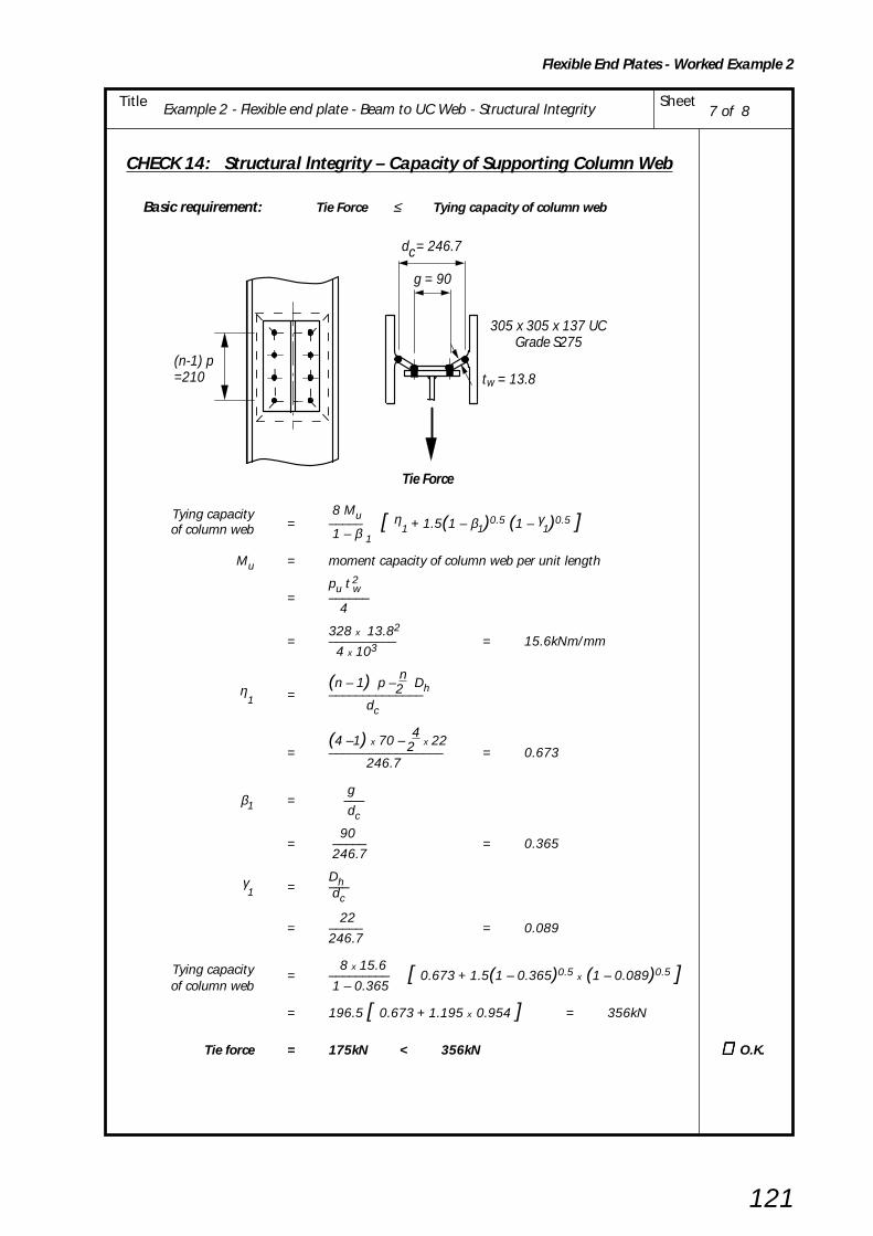
Example 2 - Flexible end plate - Beam to UC Web - Structural Integrity SheetTitle
Flexible End Plates - Worked Example 2
121
CHECK 14: Structural lntegrity – Capacity of Supporting Column Web
Basic requirement: Tie Force ≤ Tying capacity of column web
Tying capacity 8 Mu= ––––– [ η
1 + 1.5(1 – β1)0.5 (1 – γ1)0.5 ]of column web 1 – β 1
Mu = moment capacity of column web per unit length
pu t w2
= –––––– 4
328 x 13.82= –––––––––– = 15.6kNm/mm
4 x 10³
(n – 1) p – n
Dh 2η1 = ––––––––––––––
dc
(4 –1) x 70 – 4
x 22 2= ––––––––––––––––– = 0.673
246.7
gβ1 = –––
dc 90
= ––––– = 0.365 246.7
Dhγ1 = –––
dc
22= ––––– = 0.089
246.7
Tying capacity 8 x 15.6= ––––––––– [ 0.673 + 1.5(1 – 0.365)0.5
x (1 – 0.089)0.5 ]of column web 1 – 0.365
= 196.5 [ 0.673 + 1.195 x 0.954 ] = 356kN
Tie force = 175kN < 356kN ∴∴∴∴∴ O.K.
7 of 8
w
Tie Force
(n-1) p=210
g = 90
d = 246.7c
t = 13.8
305 x 305 x 137 UCGrade S275

Example 2 - Flexible end plate - Beam to UC Web - Structural IntegritySheetTitle
Flexible End Plates - Worked Example 2
122
If column web fails to satisfy the criteria shown on sheet 7 then sfiffeners fillet welded on one
side to the web and flanges would be required thus:
8 of 8

Example 3 - Flexible End Plates - Beam to RHS using Flowdrill SheetTitle
Flexible End Plates- Worked Example 3
123
BCSA
CALCULATIONSHEET
Calcs by
Title
Client
Checked by Date
Job Sheet
Joints in Steel Construction - Simple Connections
Example 3 - Flexible End Plates - Beam to RHS using Flowdrill
SCI/BCSA Connections Group
RS AW / AM May 2002
1 of 12
REF.
See Figure 5.5and
Yellow PagesTable H.3
DESIGN EXAMPLE 3
Check the following beam to RHS column connection for the design forces shown using Grade 8.8bolts in Flowdrill threaded holes in the column.
In this example the tie force is less than the shear force. The tie force has been derived on the basisthat the floor beams are supplemented as ties by the use of reinforcement bars located in the slab.It is important that the reinforcement is adequately anchored to the steelwork for it to beeffective in resisting tie forces.
Note: The connections should be checked independently for (i) Shear forces and (ii) Tie forcesand NOT for both forces acting at the same time
Yellow pages used for initial selection of end plates.
Design Information:Bolts: M20 8.8, Flowdrill
Welds: 6mm filletColumn: S355Beams: S275
End plates: S275
40
70
70
70
70
7040
8
400kN 550kN
406 x 178 x 74 UBGrade S275
200kNtie
force
40
70
70
70
250 x 250 x 12.5 RHSGrade S355
10
533 x 210 x 92 UBGrade S275
275kNtie
force
40
90
150 x 8 flexible end plate(Type EA4) Grade S275
200 x 10 flexible end plate(Type EB6)
Grade S275
140
Flowdrill

Example 3 - Flexible End Plates - Beam to RHS using Flowdrill SheetTitle
Flexible End Plates - Worked Example 3
124
400kN 550kN
406 x 178 x 74 UBGrade S275
200kNtie
force
250 x 250 x 12.5 RHSGrade S355
533 x 210 x 92 UBGrade S275
275kNtie
force
1
2 of 12
CONNECTION DESIGN USING CAPACITY TABLES FROM YELLOW PAGES
406 x 178 x 74 UB Grade S275 533 x 210 x 92 UB Grade S275
End plate type EA4 End plate type EB6
Welds 6mm fillet Welds 6mm fillet
Bolts M20 8.8 Bolts M20 8.8
Bolts at 90 cross centres Bolts at 140 cross centres
4 rows of bolts 6 rows of bolts
From Capacity Table H.20 in yellow pages From Capacity Table H.20 in yellow pages
Connection shear capacity Connection shear capacity
= 409kN > 400kN = 645kN > 550kN ∴∴∴∴∴ O.K.
Minimum support thickness Minimum support thickness
= 4.6mm < 12.5mm = 4.9mm < 12.5mm ∴∴∴∴∴ O.K.
Connection tying capacity Connection tying capacity
= 239kN > 200kN ∴ ∴ ∴ ∴ ∴ O.K. = 270kN > 275kN ∴∴∴∴∴ FAILS |
The beam side of the connection is adequate The beam side of the connection fails dueto insufficient tying capacity. End platethickness may be increased to 12mm.
Note:(1) The tying capacity of the connection given in the tables in the yellow pages is the least value
obtained from CHECKS 11, 12 and 13.
(2) Beams connecting to RHS wall must also be checked for RHS wall bending as shown inCHECK 15 (Sheet 11 & 12).
Yellow PagesTable H.20

Example 3 - Flexible End Plates - Beam to RHS using Flowdrill SheetTitle
Flexible End Plates- Worked Example 3
125
3 of 12
SUMMARY OF FULL DESIGN CHECKS FOR EXAMPLE 3 Notes (i) CHECKS 1 to 9, where applicable, are generally as shown in Example 1 and are not repeated in this example,
but the calculated capacities are summarised below.
(ii) In accordance with BS 5950-1; tie forces are ignored when checking the capacity to resist vertical reactionsand vertical reactions are ignored when calculating the capacity to resist tie forces.
(iii) Values shown * are different to Example 1. Example 1 uses 10mm plate whereas Example 3 uses 8mm plate.
406UB 533UB RHS Column S355
Sheet CHECK
S275 S275 406UB Side 533UB Side
Nos Capacity
Applied Capacity
AppliedCapacity
Applied Capacity
AppliedLoad Load Load Load
CHECK 1 Recommended detailing practice All recommendations adopted
CHECK 2 Supported Beam- Weld Capacity (kN) 514 400 772 550 Not Applicable
CHECK 3 Not Applicable
CHECK 4 Supported Beam Shear 409 400 645 550 Not Applicable - Capacity at connection (kN) CRITICAL CHECK FOR VERTICAL SHEAR
CHECKS 5, 6, 7 Not Applicable Not Applicable
CHECK 8 Supporting Column Shear - bolt 735 400 1103 550 Not Applicable - Bolt Group shear capacity group (kN)
CHECK 9 Shear (kN) 320* 200 589 275Not Applicable Supporting Column Bearing 294* 200 552 275
- Connecting Element (Capacity (Strength of plate)
per boltline, kN)
4 & 5 CHECK 10 Shear (kN) 940 200 1367 275
Supporting Beam - Capacity Not Applicable (Local capacity of beam web) Bearing (per 138 50.0 138 45.8
bolt, kN)
CHECK 11Tension 239 200 270 275 Not Applicable 6 & 7 Structural Integrity
FAILS - Connecting Elements (kN) (TIE FORCE) Tension capacity of end plate
CHECK 12Tension 758 200 1194 275 Not Applicable 8 & 9 Structural Integrity
- Supported Beam. (kN) Tension capacity of beam web
10 CHECK 13 Structural Integrity Tension - Tension bolt group (kN) Not Applicable 584 200 876 275 - Welds 650 200 974 275
10 CHECK 14 Not Applicable Not Applicable
CHECK 1511&12 Structural Integrity -
Tension Not Applicable 400 200 787 275
Supporting column wall (kN)
See
Exa
mpl
e 1
Sh
eets
4 t
o 1
1
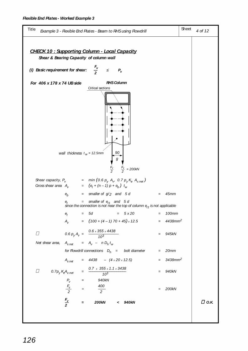
Example 3 - Flexible End Plates - Beam to RHS using Flowdrill SheetTitle
Flexible End Plates - Worked Example 3
126
CHECK 10 : Supporting Column - Local Capacity Shear & Bearing Capacity of column wall
Fv(i) Basic requirement for shear: –– ≤ Pv2
For 406 x 178 x 74 UB side
Shear capacity, Pv = min (0.6 py Av, 0.7 py Ke Av.net )Gross shear area Av = (et + (n – 1) p + eb ) tw
eb = smaller of g/2 and 5 d = 45mm
et = smaller of et1 and 5 dsince the connection is not near the top of column et1 is not applicable
et = 5d = 5 x 20 = 100mm
Av = (100 + (4 – 1) 70 + 45) x 12.5 = 4438mm2
0.6 x 355 x 4438∴ 0.6 py Av = –––––––––––––––– = 945kN 103
Net shear area, Av.net = Av – n Dh tw
for Flowdrill connections Dh = bolt diameter = 20mm
Av.net = 4438 – (4 x 20 x 12.5) = 3438mm2
0.7 x 355 x 1.1 x 3438∴ 0.7py KeAv.net = –––––––––––––––––––– = 940kN 103
Pv = 940kN
Fv 400 ––– = –––– = 200kN 2 2
Fv–– = 200kN < 940kN ∴∴∴∴∴ O.K.2
4 of 12
RHS ColumnCritical sections
22
gwall thickness wt = 12.5mm 90
= 200kNFv Fv

Example 3 - Flexible End Plates - Beam to RHS using Flowdrill SheetTitle
Flexible End Plates- Worked Example 3
127
RHS ColumnCritical sections
gwall thickness wt = 12.5mm 140
= 275kN2Fv
2Fv
For 533 x 210 x 92 UB side
eb = smaller of g/2 and 5d = 70mm
et = 5d = 5 x 20 = 100mm
Av = (100 + (6 – 1) 70 + 70) x 12.5 = 6500mm2
0.6 x 355 x 6500∴ 0.6 py Av = –––––––––––––––– = 1385kN103
Av.net = 6500 – (6 x 20 x 12.5) = 5000mm2
0.7 x 355 x 1.1 x 5000 ∴ 0.7 py Ke Av.net = –––––––––––––––––––– = 1367kN
103
Pv = 1367kN
Fv–– = 275kN < 1367kN ∴∴∴∴∴ O.K. 2
Note: The above check is for local shear only; the effects of any global shear forces must also be considered.
Fv(ii) Basic requirement for bearing: –– ≤ Pbs2nBearing capacity of column wall per bolt, Pbs = kbs d tw pbs
1.0 x 20 x 12.5 x 550= ––––––––––––––––––– = 138kN
103
For 406 x 178 x 74 UB side
Fv 400–––– = ––––– = 50.0kN < 138kN ∴∴∴∴∴ O.K. 2n 2 x 4
For 533 x 210 x 92 UB side
Fv 550–––– = ––––– = 45.8kN < 138kN ∴∴∴∴∴ O.K. 2n 2 x 6
5 of 12
pbs fromBS 5950-1Table 32

Example 3 - Flexible End Plates - Beam to RHS using Flowdrill SheetTitle
Flexible End Plates - Worked Example 3
128
6 of 12
CHECK 11: Structural Integrity - Connecting Elements
Tension Capacity of End Plate
Basic requirement: Tie Force ≤ Tying capacity of end plate
For 406 x 178 x 74 UB side
s = leg length of weld= 6 mm
tw = web thickness
= 9.5mm
1c1 = –– ( g – tw – 2s ) 2
1
= –– ( 90 – 9.5 – 2 x 6 ) 2
= 34.3mm
2 (MuA + MuB) Tying capacity of end plate = –––––––––––––
L
pu LeA tp2
Moment capacity of end plate MuA = ––––––––––– at section AA 4
pu = design tensile strength = 328N/mm2 (Us / 1.25)
tp = plate thickness = 8mm
LeA = eff. length of plastic hinge at section AA
= 2eeA + (n – 1)peA
eeA = e1 but ≤ e2 = 30mm
peA = p but ≤ 2e2 = 60mm
∴ LeA = (2 x 30) + (4 – 1)60 = 240mm
328 x 240 x 82∴ MuA = ––––––––––––– = 1260kNmm
4 x 10³
Moment capacity of end plate MuBpu LeB tp
2
at section BB = –––––––––– 4
LeB = eff. length of plastic hinge at section BB
= 2eeB + (n – l)peB
For Flowdrill connections Dh = hole diameter in plate = 22mm
eeB = e1 but ≤ c1 + Dh/2 = 40mm
c1 + Dh/2 = 34.35 + 22/2 = 45.3mm
peB = p but ≤ 2c1 + Dh = 70mm
2c1 + Dh = 2 x 34.3 + 22 = 90.6mm
∴ LeB = (2 x 40) + (4 –1)70 = 290mm
328 x 290 x 82∴ MuB = ––––––––––––– = 1522kNmm
4 x 10³
L = distance between plastic hinges = c1 – (Dh/2)
= 34.3 – (22/2) = 23.3mm
2(MuA + MuB) 2 x (1260 + 1522)–––––––––––– = ––––––––––––––– = 239kN
L 23.3Tie force = 200kN < 239kN ∴∴∴∴∴ O.K.
Yellow pagesTable H.60
g = 90
e = 401
p = 70
n rows
e = 401
c = 34.3
200 kN
1
A B
A BL = 23.3

Example 3 - Flexible End Plates - Beam to RHS using Flowdrill SheetTitle
Flexible End Plates- Worked Example 3
129
For 533 x 210 x 92 UB side
s = leg length of weld
= 6 mm
tw = web thickness
= 10.1mm
1c1 = –– ( g – tw – 2s )2
1= –– ( 140 – 10.1 – 2 x 6 )
2
= 59.0mm
2 (MuA + MuB)Tying capacity of end plate = –––––––––––––
L
pu LeA tp2
Moment capacity of end plate MuA = ––––––––––– at section AA 4
pu = design tensile strength = 328N/mm2 (Us / 1.25)
tp = plate thickness = 10mm
LeA = eff. length of plastic hinge at section AA
= 2eeA + (n – 1)peA
eeA = e1 but ≤ e2 = 30mm
peA = p but ≤ 2e2 = 60mm
∴ LeA = (2 x 30) + (6 – 1)60 = 360mm
328 x 360 x 102∴ MuA = ––––––––––––– = 2952kNmm
4 x 10³
Moment capacity of end plate MuBpu LeB tp
2= ––––––––––
at section BB 4
LeB = eff. length of plastic hinge at section BB
= 2eeB + (n – 1)peB For Flowdrill connections Dh = hole diameter in plate = 22mm
eeB = e1 but ≤ c1 + Dh/2 = 40mm
c1 + Dh/2 = 59.0 + 22/2 = 70.0mm
peB = p but ≤ 2c1 + Dh = 70mm
2c1 +Dh = 2 x 59.0 + 22 = 140mm
∴ LeB = (2 x 40) + (6 –1)70 = 430mm
328 x 430 x 102∴ MuB = ––––––––––––– = 3526kNmm
4 x 10³
L = distance between plastic hinges = c1 – (Dh/2)
= 59.0 – 22/2 = 48.0mm
2(MuA + MuB) 2 x (2952 + 3526)–––––––––––– = ––––––––––––––– = 270kN L 48
|Tie force = 275kN < 270kN
7 of 12
Yellow pagesTable H.60
End plateFAILS
thickness maybe increased
to 12mm
g = 140
e = 401
p = 706 rows
e = 401
A B
A B
e = 30
L = 48.0
A B
c = 59.0
2
275kN
1
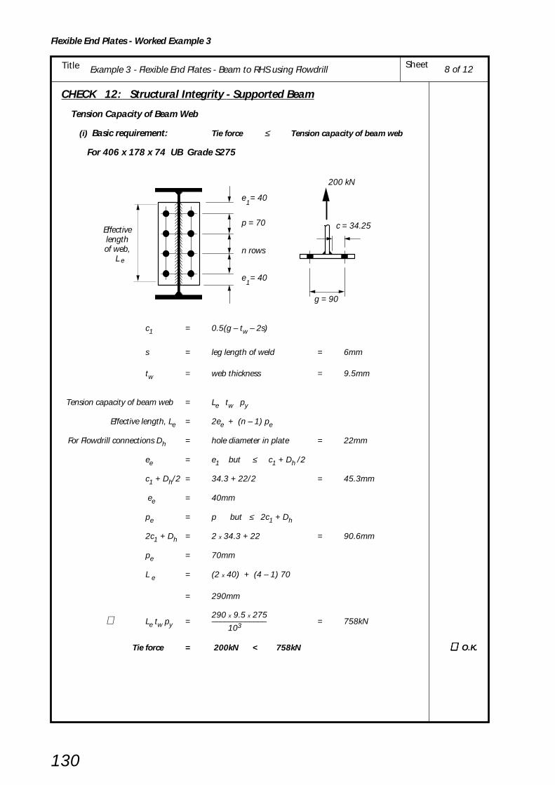
Example 3 - Flexible End Plates - Beam to RHS using Flowdrill SheetTitle
Flexible End Plates - Worked Example 3
130
CHECK 12: Structural Integrity - Supported Beam
Tension Capacity of Beam Web
(i) Basic requirement: Tie force ≤ Tension capacity of beam web
For 406 x 178 x 74 UB Grade S275
c1 = 0.5(g – tw – 2s)
s = leg length of weld = 6mm
tw = web thickness = 9.5mm
Tension capacity of beam web = Le tw py
Effective length, Le = 2ee + (n – 1) pe
For Flowdrill connections Dh = hole diameter in plate = 22mm
ee = e1 but ≤ c1 + Dh /2
c1 + Dh/2 = 34.3 + 22/2 = 45.3mm
ee = 40mm
pe = p but ≤ 2c1 + Dh
2c1 + Dh = 2 x 34.3 + 22 = 90.6mm
pe = 70mm
L e = (2 x 40) + (4 – 1) 70
= 290mm
290 x 9.5 x 275∴ Le tw py = ––––––––––––– = 758kN 103
Tie force = 200kN < 758kN ∴∴∴∴∴ O.K.
8 of 12
g = 90
e = 401
p = 70
n rows
e = 401
c = 34.25
e
Effectivelengthof web,
L
200 kN

Example 3 - Flexible End Plates - Beam to RHS using Flowdrill SheetTitle
Flexible End Plates- Worked Example 3
131
For 533 x 210 x 92 UB Grade S275
c1 = 0.5 (g – tw – 2s)
s = leg length of weld = 6mm
tw = web thickness = 10.1mm
Tension capacity of beam web = Le tw py
Effective length, Le = 2ee + (n – 1) pe
For Flowdrill connections Dh = hole diameter in plate = 22mm
ee = e1 but ≤ c1 + Dh /2
c1 + Dh/2 = 59.0 + 22/2 = 70.0mm
ee = 40mm
pe = p but ≤ 2c1 + Dh
2c1 + Dh = 2 x 59.0 + 22 = 140mm
pe = 70mm
L e = (2 x 40) + (6 – 1) 70
= 430mm
430 x 10.1 x 275∴ Le tw py = ––––––––––––– = 1194kN 103
Tie force = 275kN < 1194kN ∴∴∴∴∴ O.K.
9 of 12
g = 140
e = 401
p = 706 rows
e = 401
c = 59.0
e
275 kN
1Effectivelengthof web,
L

Example 3 - Flexible End Plates - Beam to RHS using Flowdrill SheetTitle
Flexible End Plates - Worked Example 3
132
CHECK 13 : Structural Integrity - Tension Capacity of Bolts and Welds
(i) Tension capacity of bolts Basic requirement: Tie Force ≤ Tension capacity of bolt group
Tension capacity = 2 n Psiof bolt group
Psi = Flowdrill Structural integrity Tensile Capacity taken from the Yellow pages
= 73kN for a grade 8.8 bolt in a 12.5mm RHS column wall
For 406 x 178 x 74 UB Side Tension capacity
= 2 x 4 x 73 = 584kN of bolt group
Tie Force = 200kN < 584kN ∴∴∴∴∴ O.K.
For 533 x 210 x 92 UB Side Tension capacity
= 2 x 6 x 73 = 876kN of bolt group
Tie force = 275kN < 876kN ∴∴∴∴∴ O.K.(ii) Weld Tension Capacity
Basic requirement: Tie force < Tie capacity of weld
Tension capacity of weld = 2 ( 1.25 pw a ( Le – 2s ) )
For 406 x 178 x 74 UB Side
Le = 290mm
pw = 220N/mm2
a = 0.7 s = 0.7 x 6 = 4.2mm
2 x( 1.25 x 220 x 4.2 x ( 290 – 2 x 6 ))∴ Tension capacity of weld = –––––––––––––––––––––––––––––––––103
= 642kN
Tie force = 200kN < 642kN ∴∴∴∴∴ O.K.
For 533 x 210 x 92 UB Side
Le = 430mm2 x (1.25 x 220 x 4.2 x ( 430 - 2 x 6 ))
∴ Tension capacity of weld = –––––––––––––––––––––––––––––––––103
= 966kN
Tie force = 275kN < 966kN ∴∴∴∴∴ O.K.
CHECK 14: not applicable
10 of 12
Tension bolt group
n rowsof bolts
p
p
p
Tie force
Critical weld
g
c
e1
e1
1
Flowdrill
Pull-outCapacity
Yellow pagesTable H.55b
Le fromCheck 12Sheet 8pw from
BS 5950-1Table 37
Le fromCheck 12Sheet 9

Example 3 - Flexible End Plates - Beam to RHS using Flowdrill SheetTitle
Flexible End Plates- Worked Example 3
133
CHECK 15: Structural lntegrity – Capacity of Supporting Column Wall (RHS)
Basic requirement: Tie Force ≤ Tying capacity of RHS column wall
For 406 x 178 x 74 UB Side
Tying capacity 8 Mu= ––––– [ η
1 + 1.5(1 – β1)0.5 (1 – γ1)0.5 ]of column wall 1 – β 1
Mu = moment capacity of RHS column wall per unit length
pu t w2
= –––––– 4
392 x 12.52= –––––––––– = 15.3kNm/mm
4 x 10³
Dh = 20mm (Bolt diameter for Flowdrill)
(n – 1) p – n
Dh 2η1 = ––––––––––––––
B – 3tw
(4 –1) 70 – 4
x 20 2= –––––––––––––––– = 0.8
250 – 3 x 12.5
gβ1 = ––––––
B – 3tw 90
= ––––– = 0.424 212.5
Dhγ1 = ––––––
B – 3tw 20
= ––––– = 0.094212.5
Tying capacity 8 x 15.3= ––––––––– [ 0.8 + 1.5(1 – 0.424)0.5
x (1 – 0.094)0.5 ]of column wall 1 – 0.424
= 212.5 [ 0.8 + 1.5 x 0.759 x 0.952 ] = 400kN
Tie force = 200N < 400kN ∴∴∴∴∴ O.K.
Tie Force
90 for 406 x 178 UB 140 for 533 x 210 UB
t = 12.5 w
B = 250
p (n-1)pg =
250 x 250 x 12.5 RHSGrade S355
11 of 12
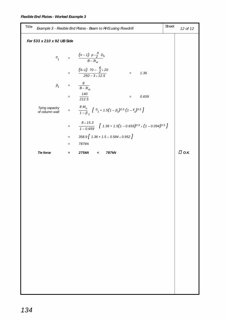
Example 3 - Flexible End Plates - Beam to RHS using Flowdrill SheetTitle
Flexible End Plates - Worked Example 3
134
For 533 x 210 x 92 UB Side
(n – 1) p – n
Dh 2η1 = ––––––––––––––
B – 3tw
(6–1) 70 – 6
x 20 2= –––––––––––––––– = 1.36
250 – 3 x 12.5
gβ1 = ––––––
B – 3tw 140
= ––––– = 0.659 212.5
Tying capacity 8 Mu= ––––– [ η
1 + 1.5(1 – β1)0.5 (1 – γ1)0.5 ]of column wall 1 – β 1
8 x 15.3= ––––––––– [ 1.36 + 1.5(1 – 0.659)0.5
x (1 – 0.094)0.5 ] 1 – 0.659
= 358.9 [ 1.36 + 1.5 x 0.584 x 0.952 ]
= 787kN
Tie force = 275kN < 787kN ∴∴∴∴∴ O.K.
12 of 12
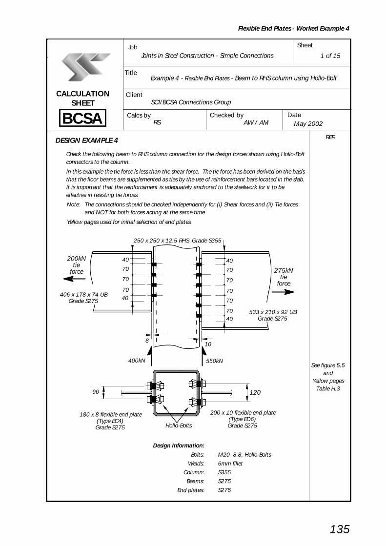
Example 4 - Flexible End Plates - Beam to RHS column using Hollo-Bolt SheetTitle
Flexible End Plates - Worked Example 4
135
BCSA
CALCULATIONSHEET
Calcs by
Title
Client
Checked by Date
Job Sheet
Joints in Steel Construction - Simple Connections
Example 4 - Flexible End Plates - Beam to RHS column using Hollo-Bolt
SCI/BCSA Connections Group
RS AW / AM May 2002
DESIGN EXAMPLE 4
Check the following beam to RHS column connection for the design forces shown using Hollo-Boltconnectors to the column.
In this example the tie force is less than the shear force. The tie force has been derived on the basisthat the floor beams are supplemented as ties by the use of reinforcement bars located in the slab.It is important that the reinforcement is adequately anchored to the steelwork for it to beeffective in resisting tie forces.
Note: The connections should be checked independently for (i) Shear forces and (ii) Tie forcesand NOT for both forces acting at the same time
Yellow pages used for initial selection of end plates.
Design Information:
Bolts: M20 8.8, Hollo-Bolts
Welds: 6mm fillet
Column: S355
Beams: S275
End plates: S275
1 of 15
REF.
See figure 5.5and
Yellow pagesTable H.3
40
70
70
70
70
7040
8
400kN 550kN
406 x 178 x 74 UBGrade S275
200kNtie
force
40
70
70
70
250 x 250 x 12.5 RHS Grade S355
10
533 x 210 x 92 UBGrade S275
275kNtie
force
40
180 x 8 flexible end plate(Type EC4)Grade S275
200 x 10 flexible end plate(Type ED6)Grade S275
12090
Hollo-Bolts

Example 4 - Flexible End Plates - Beam to RHS column using Hollo-Bolt SheetTitle
Flexible End Plates - Worked Example 4
136
2 of 15
CONNECTION DESIGN USING CAPACITY TABLES FROM YELLOW PAGES
406 x 178 x 74 UB Grade S275 533 x 210 x 92 UB Grade S355End plate type EC4 End plate type ED6Welds 6mm fillet Welds 6mm filletBolts M20 8.8 Bolts M20 8.8
Bolts at 90 cross centres Bolts at 120 cross centres
4 rows of bolts 4 rows of bolts
From Capacity Table H.22 in yellow pages From Capacity Table H.22 in yellow pages
Connection shear capacity Connection shear capacity
= 409kN > 400kN = 645kN > 550kN ∴∴∴∴∴ O.K.
Minimum support thickness Minimum support thickness
= 4.8mm < 12.5mm = 4.9mm < 12.5mm ∴∴∴∴∴ O.K.
Connection tying capacity Connection tying capacity
= 363kN > 200kN = 448kN > 275kN ∴∴∴∴∴ O.K.
The beam side of the connection is adequate The beam side of the connection is adequate
Note:
(1) The tying capacity of the connection given in the tables in the yellow pages is the least valueobtained from CHECKS 11, 12 and 13.
(2) Beams connecting to RHS wall must also be checked for RHS wall bending as shown in CHECK 15.
Yellow PagesTable H.22
400kN 550kN
406 x 178 x 74 UBGrade S275
200kNtie
force
250 x 250 x 12.5 RHS Grade S355
533 x 210 x 92 UBGrade S275
275kNtie
force

Example 4 - Flexible End Plates - Beam to RHS column using Hollo-Bolt SheetTitle
Flexible End Plates - Worked Example 4
137
2 of 15
SUMMARY OF FULL DESIGN CHECKS FOR EXAMPLE 4 Notes (i) Checks 1 to 4, where applicable are all as shown in Example 1 and are not repeated in this example but
the calculated capacities are summarised below.
(ii) In accordance with BS 5950-1; tie forces are ignored when checking the capacity to resist verticalreactions and vertical reactions are ignored when calculating the capacity to resist tie forces.
406UB 533UB RHS Column (S355)
Sheet CHECK
(S275) (S275) 406UB Side 533UB Side
NosCapacity
AppliedCapacity
AppliedCapacity
AppliedCapacity
AppliedLoad Load Load Load
CHECK 1All recommendations adopted- Recommended detailing practice
CHECK 2 514 400 772 550 Not ApplicableSupported Beam - Weld Capacity (kN)
CHECK 3 Not Applicable Not Applicable
CHECK 4Supported Beam Shear 409 400 645 550- Capacity at connection (kN) CRITICAL CHECK, VERTICAL SHEAR
Not Applicable
CHECK 5, 6, 7 Not Applicable Not Applicable
CHECK 8747 400 1184 550 Not Applicable4 Supporting Column Shear - bolt
- Bolt Group shear capacity group (kN)
CHECK 9 Shear (kN) 224 200 409 275 Not Applicable5 & 6 Supporting Column Bearing 294 200 552 275
- Connecting Element (Capacity(Strength of plate) per bolt
line, kN)
7 & 8 CHECK 10 Shear (kN) 735 200 1025 275Supporting Beam - Capacity Bearing Not Applicable
138 50.0 138 45.8(Local capacity of beam web) (Capacity
per bolt,kN)
9 & 10 CHECK 11Tension 362 200 448 275 Not ApplicableStructural Integrity
- Connecting Elements (kN) CRITICAL CHECK, TIE FORCE Tension capacity of end plate
11 & CHECK 12Tension 758 200 1194 275 Not Applicable 12 Structural Integrity
-Supported Beam (kN) Tension capacity of beam web
13 CHECK 13Structural Integrity Tension 584 200 876 275 - Tension bolt group (kN) Not Applicable - Welds 650 200 974 275
13 CHECK 14 Not Applicable Not Applicable
14 & CHECK 15 15 Structural Integrity Tension Not Applicable 361 200 578 275
- Supporting column wall (kN)
See
Exa
mpl
e 1
Shee
ts 4
to
5

Example 4 - Flexible End Plates - Beam to RHS column using Hollo-Bolt SheetTitle
Flexible End Plates - Worked Example 4
138
CHECK 8: Supporting Column - Bolt Group
Basic requirement: Fv ≤ Σ Σ Σ Σ Σ Ps
For 406 x 178 x 74 UB side
Shear capacity of single bolt, Ps = ps As
For M20 Hollo-Bolts
Shear Capacity Ps = 100kN
But for top pair of boltsPs = min ( ps As , 0.5 kbs e1 tp pbs )( where kbs = 1.0 )
0.5 x 1.0 x 40 x 8 x 460 0.5 kbs e1 tp pbs = ––––––––––––––––––– = 73.6kN
103
Σ Ps = 6 x 100 + 2 x 73.6 = 747kN
Fv = 400kN < 747kN ∴∴∴∴∴ O.K.
For 533 x 210 x 92 UB side
0.5 x 1.0 x 40 x 10 x 460 0.5 kbs e1 tp pbs = –––––––––––––––––––– = 92 kN
103
Σ Ps = 10 x 100 + 2 x 92 = 1184kN
Fv = 550kN < 1184kN ∴∴∴∴∴ O.K.
4 of 15
400kN
e = 40
406 x 178 x 74 UB
250 x 250 x 12.5 RHS
1
550kN
e = 40
533 x 210 x 92 UB
250 x 250 x 12.5 RHS
1
ps fromYellow pagesTable H.56
pbs fromBS 5950-1Table 32
pbs fromBS 5950-1Table 32

Example 4 - Flexible End Plates - Beam to RHS column using Hollo-Bolt SheetTitle
Flexible End Plates - Worked Example 4
139
5 of 15
CHECK 9: Supporting Column - Connecting elements Shear and bearing of end plates connected to supporting column
Fv(i) Basic requirement for shear: –– ≤ Pv.min2 For 406 x 178 x 74 UB
Shear capacity of end plate Pv.min is the smaller of plain shear capacity Pv and block shear capacity Pr
Plain Shear capacity Pv = min ( 0. 6 py Av , 0.7 py Ke A v.net )
Shear area, Av = 0.9 (2e1 + (n – 1) p ) tp
= 0.9 (80 + 210 ) x 8 = 2088mm2
Net area, Av.net = Av – n Dh tpfor Hollo-Bolt connections Dh = 35mm
Av.net = 2088 – (4 x 35 x 8) = 968mm2
0.6 x 275 x 20880.6 py Av = –––––––––––––– = 344kN
103
0.7 x 275 x 1.2 x 9680.7 py Ke A v.net = –––––––––––––––––– = 224kN
103
Plain shear capacity Pv = 224kN
Block Shear capacity Pr = 0.6py tp ( Lv + Ke ( Lt – kDh )) Lv = e1 + (n – 1)p = 40 + 210 = 250mm
Lt = e2 = 45mm
k = 0.5
Ke = 1.2 (for S275)
0.6 x 275 x 8 x (250 + 1.2(45 – 0.5 x 35))∴ Pr = ––––––––––––––––––––––––––––––––––––103
= 374kN
Pv.min = min (Pv , Pr )
= 224kNFv/2 = 200kN < 224kN ∴ ∴ ∴ ∴ ∴ O.K.
For 533 x 210 x 92 UB sideAv = 0.9(80 + 350) x 10 = 3870mm2
Av.net = 3870 – (6 x 35 x 10) = 1770mm2
0.6 x 275 x 38700.6 py Av = ––––––––––––––– = 639kN
103
0.7 x 275 x 1.2 x 17700.7 py Ke A v.net = ––––––––––––––––––– = 409kN
103
∴Pv = 409kN
0.6 x 275 x 10 x (390 + 1.2(40 – 0.5 x 35)) Pr = ––––––––––––––––––––––––––––––––––––
103
= 688kN
Pv.min = min ( Pv , Pr )
= 409kN
Fv/2 = 275kN < 409kN ∴ ∴ ∴ ∴ ∴ O.K.
Note: Block shear checks have been shown here, but they are never critical for well proportioned end plates.However, if the bolt spacing is concentrated at one part of a plate then these checks may be critical.
2
= 400kN
2
e 1
1e
(n-1) p= 210
= 40
= 40Fv Fv
Fv
e 2 = 45
= 40
= 40
= 350(n – 1) p
e 1
1e
–2 2
–
= 550kN
Fv Fv
Fv
e 2 = 40
Dh fromYellow pages
Table H.3
See Notebelow
See Notebelow

Example 4 - Flexible End Plates - Beam to RHS column using Hollo-Bolt SheetTitle
Flexible End Plates - Worked Example 4
140
Fv(ii) Basic requirement for bearing:
–– ≤ ΣΣΣΣΣ Pbs2
For 406 x 178 x 74 UB side
Bearing capacity, Pbs = kbs d tp pbs
but for the top bolt, Pbs = min ( kbs d tp pbs , 0.5kbs e1 tp pbs )
for Hollo-bolt connections d = nominal bolt diameter = 20mm
1.0 x 20 x 8 x 460 kbs d tp pbs = –––––––––––––––– = 73.6kN
103
0.5 x 1.0 x 40 x 8 x 460 0.5 kbs e1 tp pbs = –––––––––––––––––––– = 73.6kN
103
Σ Pbs = 3 x 73.6 + 73.6 = 294kN
Fv–– = 200kN < 294kN ∴ ∴ ∴ ∴ ∴ O.K.2
For 533 x 210 x 92 UB side
Bearing capacity, Pbs = kbs d tp pbs
but for the top bolt, Pbs = min ( kbs d tp pbs , 0.5kbs e1 tp pbs )
1.0 x 20 x 10 x 460 kbs d tp pbs = ––––––––––––––––– = 92kN
103
0.5 x 1.0 x 40 x 10 x 460 0.5 kbs e1 tp pbs = –––––––––––––––––––– = 92kN
103
Σ Pbs = 5 x 92 + 92 = 552kN
Fv–– = 275kN < 552kN ∴∴∴∴∴ O.K.2
6 of 15
pbs fromBS 5950-1Table 32

Example 4 - Flexible End Plates - Beam to RHS column using Hollo-Bolt SheetTitle
Flexible End Plates - Worked Example 4
141
CHECK 10 : Supporting Column - Local Capacity
Shear & Bearing Capacity of column wall
Fv(i) Basic requirement for shear: –– ≤ Pv2
For 406 x 178 x 74 UB side
Shear capacity, Pv = min (0.6 py Av , 0.7 py Ke Av.net )
Gross shear area, Av = (et + (n – 1) p + eb ) twfor Hollo-Bolt connection d = bolt diameter = 20mm
eb = smaller of g/2 and 5 d = 45mm
et = smaller of et1 and 5 d
since the connection is not near the top of column et1 is not applicable
et = 5d = 5 x 20 = 100mm
Av = (100 + (4 – 1) 70 + 45) x 12.5 = 4438mm2
0.6 x 355 x 4438 ∴ 0.6 py Av = –––––––––––––––– = 945kN
103
Net shear area, Av.net = Av – n Dh tw
for Hollo-Bolt connections Dh = hole diameter = 35mm
Av.net = 4438 – (4 x 35 x 12.5) = 2688mm2
0.7 x 355 x 1.1 x 2688 ∴ 0.7 py Ke Av.net = –––––––––––––––––––– = 735kN
103
∴ Pv = 735kN
Fv–– = 200kN < 735kN ∴∴∴∴∴ O.K.2
7 of 15
RHS Column Grade S355Critical sections
22
wall thickness wt = 12.5mm
g = 90
= 200kNFv Fv
Dh fromYellow pagesTable H.61

Example 4 - Flexible End Plates - Beam to RHS column using Hollo-Bolt SheetTitle
Flexible End Plates - Worked Example 4
142
For 533 x 210 x 92 UB side
eb = smaller of g/2 and 5d = 60mm
et = 5d = 5 x 20 = 100mm
Av = (100 + (6 – 1) 70 + 60) x 12.5 = 6375mm2
0.6 x 275 x 6375∴ 0.6 py Av = –––––––––––––––– = 1052kN 103
Av.net = 6375 – (6 x 35 x 12.5) = 3750mm2
0. 7 x 355 x 1.1 x 3750∴ 0.7 py Ke Av.net = –––––––––––––––––––– = 1025kN 103
∴ Pv = 1025kN
Fv–– = 275kN < 1025kN ∴∴∴∴∴ O.K.2
Note: The above check is for local shear only; the effects of any global shear forces must also be considered.
Fv(ii) Basic requirement for bearing: –– ≤ Pbs
2n
Bearing capacity of column wall per bolt Pbs = kbsd tw pbs(where kbs = 1.0)
1.0 x 20 x 12.5 x 550= ––––––––––––––––– = 138kN
103
For 406 x 178 x 74 UB side Fv 400–––– = ––––– = 50kN < 138kN ∴∴∴∴∴ O.K. 2n 2 x 4
For 533 x 210 x 92 UB side Fv 550–––– = ––––– = 45.8kN < 138kN ∴∴∴∴∴ O.K. 2n 2 x 6
8 of 15
RHS Column Grade S355Critical sections
22
wall thickness wt = 12.5mmg = 120
= 275kNFv Fv
pbs fromBS 5950-1Table 32

Example 4 - Flexible End Plates - Beam to RHS column using Hollo-Bolt SheetTitle
Flexible End Plates - Worked Example 4
143
9 of 15
CHECK 11: Structural Integrity - Connecting Elements Tension Capacity of End Plate
Basic requirement: Tie Force ≤ Tying capacity of end plate
For 406 x 178 x 74 UB sides = leg length of weld
= 6 mm
tw = web thickness
= 9.5mm
1c1 = –– ( g – tw – 2s )2
1= –– (90 – 9.5 – 2 x 6)
2
= 34.3mm
L = c1 – Dh/2
= 34.3 – 35/2 = 16.8mm
2 (MuA + MuB)Tying capacity of end plate = –––––––––––––
L
pu LeA tp2
Moment capacity of end plate MuA = ––––––––––– at section AA 4
pu = design tensile strength = 328N/mm2 (Us / 1.25)
tp = plate thickness = 8mm
LeA = eff. length of plastic hinge at section AA
= 2eeA + (n – 1)peA
eeA = e1 but ≤ e2 = 40mm
peA = p but ≤ 2e2 = 70mm
∴ LeA = (2 x 40) + (4 – 1)70 = 290mm
328 x 290 x 82∴ MuA = ––––––––––––– = 1522kNmm
4 x 10³
Moment capacity of end plate MuBpu LeB tp
2= –––––––––– at section BB 4
LeB = eff. length of plastic hinge at section BB
= 2eeB + (n – 1)peB
eeB = e1 but ≤ c1 + Dh/2 = 40mm
Dh = 35mm (Hole diameter for Hollo-Bolt)
peB = p but ≤ 2c1 + Dh = 70mm
∴ LeB = (2 x 40) + (4 –1)70 = 290mm
328 x 290 x 82∴ MuB = ––––––––––––– = 1522kNmm
4 x 10³
L = distance between plastic hinges = c1 – (Dh/2)
= 34.3 – (35/2) = 16.8mm
2(MuA + MuB) 2(1522 + 1522)–––––––––––– = ––––––––––––––– = 362kN L 16.8
Tie force = 200N < 362kN ∴∴∴∴∴ O.K.
g = 90
e = 401
p = 70n rows
e = 401
A B
A B
e = 45
L = 16.8
A B
c = 34.3
2
1
Steel strengthsYellow pagesTable H.45
Dh fromYellow PagesTable H.61

Example 4 - Flexible End Plates - Beam to RHS column using Hollo-Bolt SheetTitle
Flexible End Plates - Worked Example 4
144
For 533 x 210 x 92 UB sides = leg length of weld
= 6 mm
tw = web thickness
= 10.1mm
1c1 = –– ( g – tw – 2s )2
1= –– (120 – 10.1 – 2 x 6 )
2
= 49mm
2 (MuA + MuB)Tying capacity of end plate = –––––––––––––
L
pu LeA tp2
Moment capacity of end plate MuA = ––––––––––– at section AA 4
pu = design tensile strength = 328N/mm2 (Us / 1.25)
tp = plate thickness = 10mm
LeA = eff. length of plastic hinge at section AA
= 2eeA + (n – 1)peA
eeA = e1 but ≤ e2 = 40mm
peA = p but ≤ 2e2 = 70mm
∴ LeA = (2 x 40) + (6 – 1)70 = 430mm
328 x 430 x 102∴ MuA = ––––––––––––– = 3526kNmm
4 x 10³
Moment capacity of end plate MuBpu LeB tp
2= –––––––––– at section BB 4
LeB = eff. length of plastic hinge at section BB
= 2eeB + (n – 1)peB
eeB = e1 but ≤ c1 + Dh/2 = 40mm
Dh = 35mm (Hole diameter for Hollo-Bolt )
peB = p but ≤ 2c1 + Dh = 70mm
∴ LeB = (2 x 40) + (6 –1)70 = 430mm
328 x 430 x 102∴ MuB = ––––––––––––– = 3526kNmm
4 x 10³
L = distance between plastic hinges = c1 – (Dh/2)
= 49 – (35/2) = 31.5mm
2(MuA + MuB) 2(3526 + 3526)–––––––––––– = ––––––––––––––– = 448kN L 31.5
Tie force = 275kN < 448kN ∴∴∴∴∴ O.K.
10 of 15
g = 120
e = 401
p = 706 rows
e = 401
A B
A B
e = 40
L = 31.5
A B
c = 49
2
1
Dh fromYellow PagesTable H.61

Example 4 - Flexible End Plates - Beam to RHS column using Hollo-Bolt SheetTitle
Flexible End Plates - Worked Example 4
145
11 of 15
CHECK 12 : Structural Integrity - Supported Beam
(i) Tension capacity of Beam web
Basic requirement: Tie force ≤≤≤≤≤ Tension capacity of beam web
For 406 x 178 x 74 Grade S275
s = leg length of weld = 6mm
tw = web thickness = 9.5mm
Dh = 35mm
1c1 = – (g – tw – 2 s)
2
1= – (90 – 9.5 – 2 x 6)
2
= 34.3mm
Tension capacity of beam web = Le tw py
Effective length, Le = 2ee + (n – 1) pe
ee = e1 but ≤ c1 + Dh /2
= 40mm (e1)
c1 + Dh/2 = 34.3 + 35/2 = 51.8mm
pe = p but ≤ 2c1 + Dh
= 70mm
2c1 + Dh = 2 x 34.3 + 35 = 103.5mm
L e = (2 x 40) + (4 – 1) 70
= 290mm
290 x 9.5 x 275∴ Le tw py = ––––––––––––– = 758kN 103
Tie force = 200kN < 758kN ∴∴∴∴∴ O.K.
g = 90
c = 34.3
200 kN
1
e = 401
p = 70
n rows
e = 401
e
Effectivelengthof web,
L
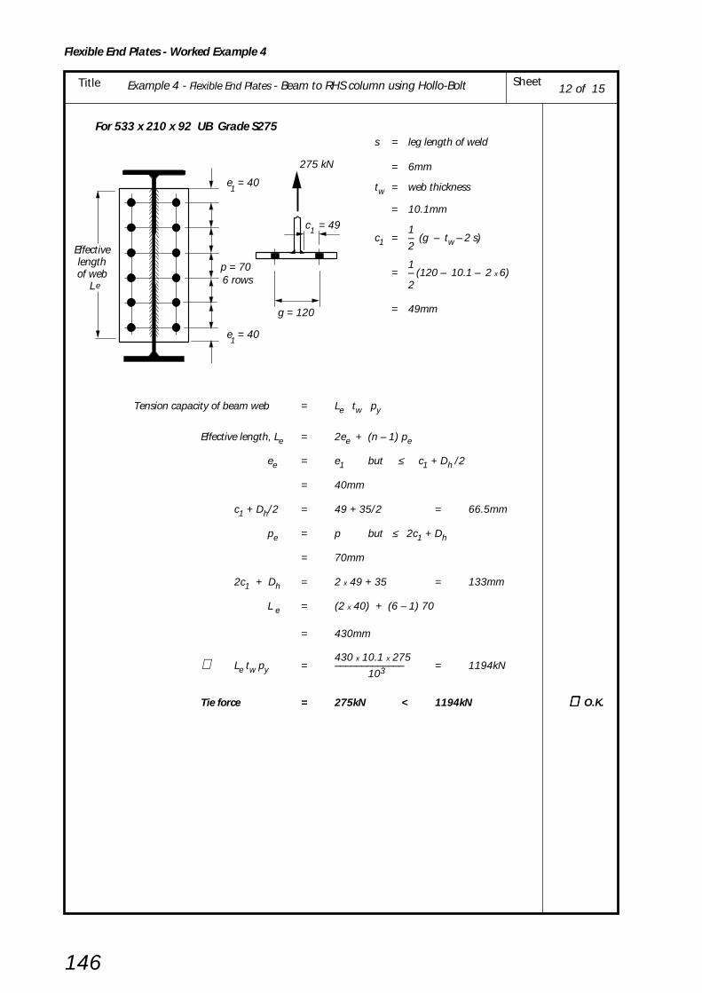
Example 4 - Flexible End Plates - Beam to RHS column using Hollo-Bolt SheetTitle
Flexible End Plates - Worked Example 4
146
For 533 x 210 x 92 UB Grade S275s = leg length of weld
= 6mm
tw = web thickness
= 10.1mm
1c1 = – (g – tw – 2 s)
2
1= – (120 – 10.1 – 2 x 6)
2
= 49mm
Tension capacity of beam web = Le tw py
Effective length, Le = 2ee + (n – 1) pe
ee = e1 but ≤ c1 + Dh /2
= 40mm
c1 + Dh/2 = 49 + 35/2 = 66.5mm
pe = p but ≤ 2c1 + Dh
= 70mm
2c1 + Dh = 2 x 49 + 35 = 133mm
L e = (2 x 40) + (6 – 1) 70
= 430mm
430 x 10.1 x 275∴ Le tw py = ––––––––––––– = 1194kN103
Tie force = 275kN < 1194kN ∴∴∴∴∴ O.K.
12 of 15
g = 120
e = 401
p = 706 rows
e = 401
c = 49
275 kN
1
Effectivelengthof web
L e

Example 4 - Flexible End Plates - Beam to RHS column using Hollo-Bolt SheetTitle
Flexible End Plates - Worked Example 4
147
CHECK 13: Structural Integrity - Tension Capacity of Bolts and Welds
(i) Tension Capacity of BoltsBasic requirement: Tie Force ≤ Tension capacity of
tension bolt group
Tension capacity = 2 n Psi
Psi = Hollo-Bolt Structural integrity
Tensile Capacity
= 73kN
For 406 x 178 x 74 UB Side
Tension capacity = 2 x 4 x 73 = 584kN
Tie force = 200kN < 584kN ∴∴∴∴∴ O.K.
For 533 x 210 x 92 UB Side
Tension capacity = 2 x 6 x 73 = 876kN
Tie force = 275kN < 876kN ∴∴∴∴∴ O.K.
(ii) Weld Tension CapacityBasic requirement: Tie force < Tie capacity of weld
Tension capacity of weld = 2 ( 1.25 pw a ( Le - 2s ) )
For 406 x 178 x 74 UB Side
Le = 290mm
pw = 220N/mm2
a = 0.7 s = 0.7 x 6 = 4.2mm
2 x( 1.25 x 220 x 4.2 x ( 290 - 2 x 6 ))∴ Tension capacity of weld = –––––––––––––––––––––––––––––––––103
= 642kN
Tie force = 200kN < 642kN ∴ ∴ ∴ ∴ ∴ O.K.
For 533 x 210 x 92 UB Side
Le = 430mm2 x( 1.25 x 220 x 4.2 x ( 430 - 2 x 6 ))
∴ Tension capacity of weld = –––––––––––––––––––––––––––––––––103
= 966kN
Tie force = 275kN < 966kN ∴ ∴ ∴ ∴ ∴ O.K.
CHECK 14: not applicable
13 of 15
Tie ForceTension
bolt group
Le fromCheck 12Sheet 11
Yellow PagesTable H.56
pw fromBS 5950-1Table 37
Le fromCheck 12Sheet 11

Example 4 - Flexible End Plates - Beam to RHS column using Hollo-Bolt SheetTitle
Flexible End Plates - Worked Example 4
148
CHECK 15: Structural lntegrity – Capacity of Supporting Column Wall (RHS)
Basic requirement: Tie Force ≤ Tying capacity of RHS column wall
For 406 x 178 x 74 UB Side
Tying capacity 8 Mu= ––––– [ η1 + 1.5(1 – β1)0.5 (1 – γ1)0.5 ]of column wall 1 – β 1
Mu = moment capacity of RHS column wall per unit length
pu t w2
= –––––– 4
392 x 12.52= –––––––––– = 15.3kNm/mm
4 x 10³
Dh = 35mm (Hole diameter for Hollo-Bolt)
(n – 1) p – n
Dh 2η1 = ––––––––––––––
B – 3tw
(4 –1) 70 – 4
x 35 2= –––––––––––––––– = 0.659
250 – 3 x 12.5
gβ1 = ––––––
B – 3tw 90
= ––––– = 0.424 212.5
Dhγ1 = ––––––
B – 3tw 35
= ––––– = 0.165212.5
Tying capacity 8 x 15.3= ––––––––– [ 0.659 + 1.5(1 – 0.424)0.5
x (1 – 0.165)0.5 ]of column wall 1 – 0.424
= 212.5 [ 0.659 + 1.5 x 0.759
x 0.914 ]= 361kN
Tie force = 200kN < 361kN ∴∴∴∴∴ O.K.
Tie Force
t = 12.5 w
B = 250
p (n-1)p 90 for 406 x 178 UB 120 for 533 x 210 UB
g =
250 x 250 x 12.5 RHS Grade S355
14 of 15

Example 4 - Flexible End Plates - Beam to RHS column using Hollo-Bolt SheetTitle
Flexible End Plates - Worked Example 4
149
15 of 15
For 533 x 210 x 92 UB Side
(n – 1) p – n
Dh 2η1 = ––––––––––––––
B – 3tw
(6–1) 70 – 6
x 35 2= –––––––––––––––– = 1.15
250 – 3 x 12.5
120β1 = ––––– = 0.565
212.5
Tying capacity 8 Mu= ––––– [ η
1 + 1.5(1 – β1)0.5 (1 – γ1)0.5 ]of column wall 1 – β 1
8 x 15.3= ––––––––– [ 1.15 + 1.5(1 – 0.565)0.5
x (1 – 0.165)0.5 ] 1 – 0.565
= 281.4 [ 1.15 + 1.5 x 0.660
x 0.914 ] = 578kN
Tie force = 275kN < 578kN ∴∴∴∴∴ O.K.

150
6. FIN PLATES
RotationFin plate connections derive their rotational capacityfrom:
(i) hole distortions in the fin plate and/or thebeam web;
(ii) out of plane bending of the fin plate;
(iii) shear deformation of the bolts.
6.1 INTRODUCTIONThe fin plate connection consists of a length of platewelded in the workshop to the supporting member (Beam,I Column, RHS Column or CHS Column) and then boltedto the supported beam web on site (See Figure 6.1).
It is popular as it can be one of the quickest connectionsto fix and overcomes the problem of shared bolts intwo-sided connections.
Figure 6.1 Fin plate. Beam-to-column and beam-to-beam connections
Untorqued bolts in clearence holes
used in all fin plate connections
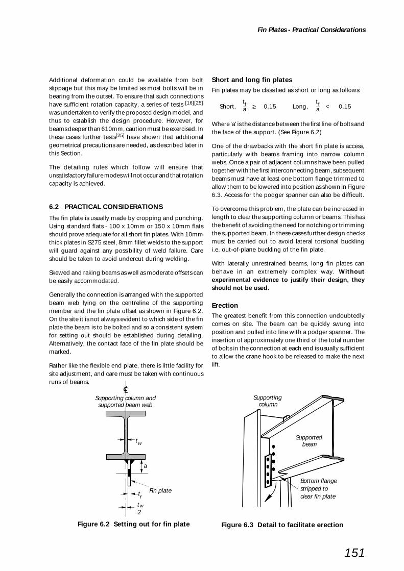
151
Additional deformation could be available from boltslippage but this may be limited as most bolts will be inbearing from the outset. To ensure that such connectionshave sufficient rotation capacity, a series of tests [16][25]
was undertaken to verify the proposed design model, andthus to establish the design procedure. However, forbeams deeper than 610mm, caution must be exercised. Inthese cases further tests[25] have shown that additionalgeometrical precautions are needed, as described later inthis Section.
The detailing rules which follow will ensure thatunsatisfactory failure modes will not occur and that rotationcapacity is achieved.
6.2 PRACTICAL CONSIDERATIONS
The fin plate is usually made by cropping and punching.Using standard flats - 100 x 10mm or 150 x 10mm flatsshould prove adequate for all short fin plates. With 10mmthick plates in S275 steel, 8mm fillet welds to the supportwill guard against any possibility of weld failure. Careshould be taken to avoid undercut during welding.
Skewed and raking beams as well as moderate offsets canbe easily accommodated.
Generally the connection is arranged with the supportedbeam web lying on the centreline of the supportingmember and the fin plate offset as shown in Figure 6.2.On the site it is not always evident to which side of the finplate the beam is to be bolted and so a consistent systemfor setting out should be established during detailing.Alternatively, the contact face of the fin plate should bemarked.
Rather like the flexible end plate, there is little facility forsite adjustment, and care must be taken with continuousruns of beams.
Short and long fin platesFin plates may be classified as short or long as follows:
tf tfShort, – ≥ 0.15 Long, – < 0.15a a
Where 'a' is the distance between the first line of bolts andthe face of the support. (See Figure 6.2)
One of the drawbacks with the short fin plate is access,particularly with beams framing into narrow columnwebs. Once a pair of adjacent columns have been pulledtogether with the first interconnecting beam, subsequentbeams must have at least one bottom flange trimmed toallow them to be lowered into position as shown in Figure6.3. Access for the podger spanner can also be difficult.
To overcome this problem, the plate can be increased inlength to clear the supporting column or beams. This hasthe benefit of avoiding the need for notching or trimmingthe supported beam. In these cases further design checksmust be carried out to avoid lateral torsional bucklingi.e. out-of-plane buckling of the fin plate.
With laterally unrestrained beams, long fin plates canbehave in an extremely complex way. Withoutexperimental evidence to justify their design, theyshould not be used.
ErectionThe greatest benefit from this connection undoubtedlycomes on site. The beam can be quickly swung intoposition and pulled into line with a podger spanner. Theinsertion of approximately one third of the total numberof bolts in the connection at each end is usually sufficientto allow the crane hook to be released to make the nextlift.
Fin Plates - Practical Considerations
Figure 6.2 Setting out for fin plate Figure 6.3 Detail to facilitate erection
a
tw2
CSupporting column andsupported beam web
Fin platetf
wt
Supporting column
Supported beam
clear fin platestripped to Bottom flange
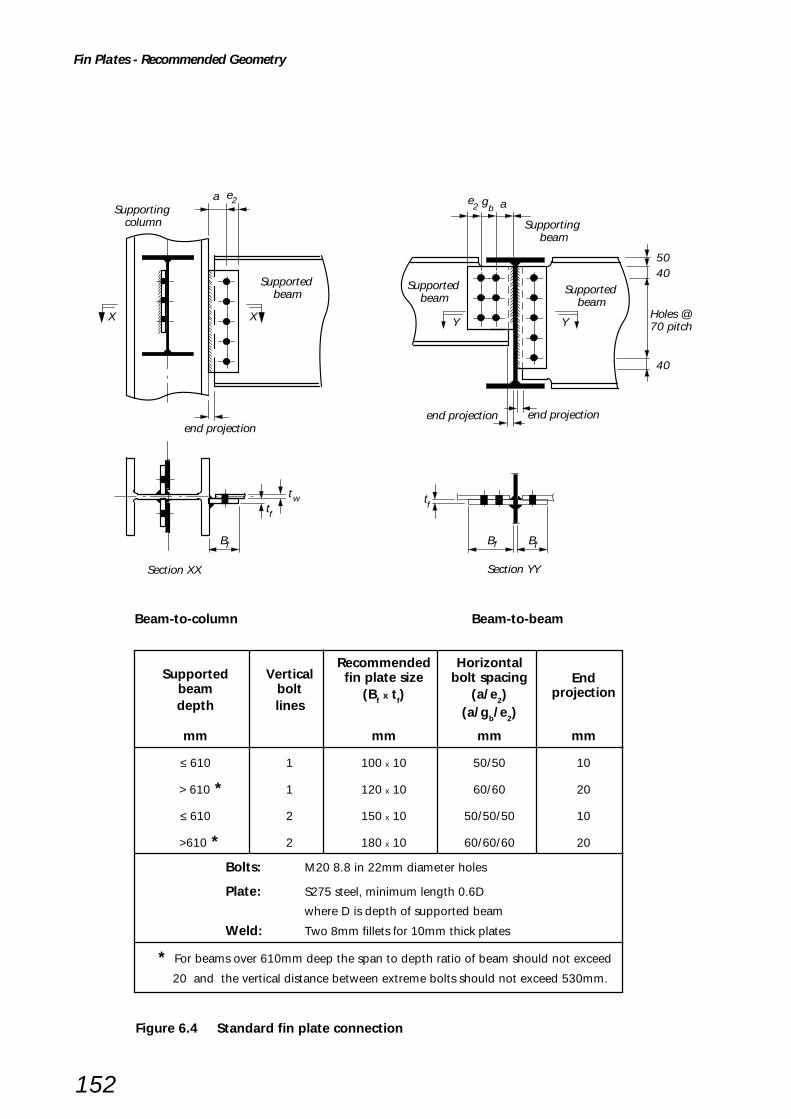
152
Fin Plates - Recommended Geometry
Supporting beam
Y Y
Section YY
Supported beam
Supporting column
end projection
XX
5040
40
t
Section XX
B B
Supported beam
Supported beam
Holes @70 pitch
end projection end projection
agb
a e2
f f
fft
tw
e2
Bf
Beam-to-column Beam-to-beam
Supported VerticalRecommended Horizontal
Endbeam bolt
fin plate size bolt spacingprojection
depth lines(Bf x tf) (a/e2)
(a/gb/e2)
mm mm mm mm
≤ 610 1 100 x 10 50/50 10
> 610 * 1 120 x 10 60/60 20
≤ 610 2 150 x 10 50/50/50 10
>610 * 2 180 x 10 60/60/60 20
Bolts: M20 8.8 in 22mm diameter holes
Plate: S275 steel, minimum length 0.6D
where D is depth of supported beam
Weld: Two 8mm fillets for 10mm thick plates
* For beams over 610mm deep the span to depth ratio of beam should not exceed
20 and the vertical distance between extreme bolts should not exceed 530mm.
Figure 6.4 Standard fin plate connection

153
6.3 RECOMMENDED GEOMETRY
The design procedures which follow set down a numberof recommended details which are intended to achievethe required flexibility for a simple connection.
When detailing the joint, the main requirements are asfollows:-
(i) the fin plate is positioned close to the top flange inorder to provide positional restraint;
(ii) the fin plate depth is at least 0.6 times the supportedbeam depth in order to provide the beam withadequate torsional restraint;
(iii) the thickness of the fin plate or the beam web is
≤ 0.42d (for S355 steel) or
≤ 0.50d (for S275 steel)(d = nominal bolt diameter);
(iv) 8.8 bolts are used, un-torqued and in clearanceholes;
(v) all end and edge distances on the plate and thebeam web are at least 2d;
(vi) the fillet weld leg length is at least 0.8 times the finplate thickness.
The first two requirements ensure that in those caseswhere the beam is laterally unrestrained, it can be designedwith an effective length of 1.0L. (BS 5950: Table 13)
The last four requirements ensure a bearing mode offailure in either the fin plate or beam web. This providesthe necessary rotational flexibility in the connection.
These requirements, together with the standard geometrypresented in Section 2, have been used to create the‘standard connection’ shown in Figure 6.4.
6.4 DESIGN
The full design procedure is presented in Section 6.5.
With a single vertical line of bolts, the connection shearcapacity will be in the range 25% to 50% of the beamshear capacity - a value similar to that of the double angleweb cleat connection. Two vertical lines of bolts do help,but as the eccentricity of the design load also increases,the benefit does not double and the best that can beachieved is around 75% of the beam shear capacity.
For connections using the standard geometry, the capacitywill generally be governed by bolt bearing (Check 2) or byshear and bending of the fin plate (Check 3).
An alternative design procedure has been developed inAustralia and this is reported in references 26 and 27.
Flexible and rigid supports
For the design of the fin plate and bolts the modelpresented in Section 6.5 assumes a line of action for theload at the point where the fin plate is welded to thesupport, i.e. the support is flexible and free to rotate.(Figure 6.5 (a)). As most supports have some rigidity,this will be found to be a slightly conservative approach.
If the fin plate support can be assumed to be rigid, forexample a heavy column flange, then there is no reasonwhy the designer should not modify the model so that theline of action is through the bolts (Figure 6.5 (b)).
Clearly the design model must be consistent, and if theabove approach is adopted, the fin plate and weld shouldbe designed for combined shear and bending moment.The column should be checked for axial load and bendingmoment based on the longer of the nominal eccentricity(100mm) or 'a'.
StiffeningIt is possible to improve the performance of a long finplate by providing some stiffening. This may either stabilisethe plate against out of plane buckling or may improvethe support provided to the plate by the supporting beamor column web. The same stiffening may achieve botheffects, see Figures 6.6 and 6.7.
One further minor consideration is the torsion introducedbecause the fin plate is attached to only one side of thesupported beam web. The test programme indicated thatthese torsions are negligible and may be ignored.
Fin Plates - Design
Figure 6.5 Flexible and rigid supports
aLine of action
Weld subject to vertical
shear only
(a) Flexible support
a Line of action
Bolt group subject to vertical
shear only
(b) Rigid support
Weld designed to resist
moment of F .a
Bolt group designed to resist
moment of F .a
F v F v
v v

154
Figure 6.7 Stiffening arrangements for long fin plates to column webs
Fin Plates - Design
Structural integrityIn certain tall multi-storey buildings there is a requirementfor the connections to be designed to carry large tyingforces. This is intended to prevent disproportionatecollapse.
Fin plate connections detailed in accordance with Figure6.4 will be found to have tying capacities which generallyexceed their shear capacity, and in this respect no furtherchecks will normally be required to the plate, weld orbeam. Local checks to the column, particularly if there areany one-sided beam to column connections, must becarried out. (See design procedure Checks 14 to 16.)
Worked examplesFour worked examples are provided in Section 6.6 toillustrate the full set of design checks of Section 6.5.
(a)Stability
(d) Substitute short fin plate
(c)Stability & stiffness
(b)In-plane stiffness
Connection capacity tablesTwo sets of capacity tables for fin plate connections withboth one and two vertical rows of bolts, using steel gradeS275 and S355 beams, detailed in accordance with thestandard geometry presented in Figure 6.4, are includedin the yellow pages.
Values of the connection shear and tying capacities aretabulated together with simple aids to check the capacityof the supporting member and the beam notch (Ifapplicable).
(a) Stability against out of plane buckling (b) Resistance to web distortion
Figure 6.6 Possible stiffening arrangement for long fin plates to supporting beam

155
Fin Plates - Design Procedures
6.5 DESIGN PROCEDURE
Recommended design modelThe design procedure applies to beams connected eitherto the column flange, the column web, the supportingbeam web, RHS columns or to CHS columns. Although thefigures show partial depth fin plates the design proceduresapply equally to full depth fin plates.
Check 1 Recommended detailing practiceCheck 2 Supported beam – Bolt groupCheck 3 Supported beam – Connecting elements Check 4 Supported beam – Capacity at the connectionCheck 5 Supported beam – Capacity at a notchCheck 6 Supported beam – Local stability of notched beamCheck 7 Unrestrained supported beam – Overall stability of notched beamCheck 8 Supporting beam/column – WeldsCheck 9 Not applicableCheck 10 Supporting beam/column – Local capacityCheck 11 Structural integrity – Connecting elementsCheck 12 Structural integrity – Supported beamCheck 13 Not applicableCheck 14 Structural integrity – Supporting column web (UC or UB)Check 15 Structural integrity – Supporting column wall (RHS)Check 16 Structural integrity – Supporting column wall (CHS)
Supporting column (I RHS or CHS)
Supported beamSingle vertical line of bolts
n rowsof bolts
n rowsof bolts
Supported beamSingle vertical line of bolts
Supporting beam
n rowsof bolts
n rowsof bolts
Supporting column (I RHS or CHS)
Supported beamDouble vertical line of bolts
Supported beamDouble vertical line of bolts
Supporting beam
Assumed line of shear transfer
(face of column)
Assumed line of shear transfer(face of web)
Assumed line of shear transfer
(face of column)
Assumed line of shear transfer(face of web)
F vFv
FvFv
Fv
For connections to the column web the d/t ratio of thecolumn should be limited to 40ε for I and hot finishedRHS and 35ε for cold formed RHS. D/t should be limitedto 50ε2 for CHS.
275 0.5
ε = (–––) py
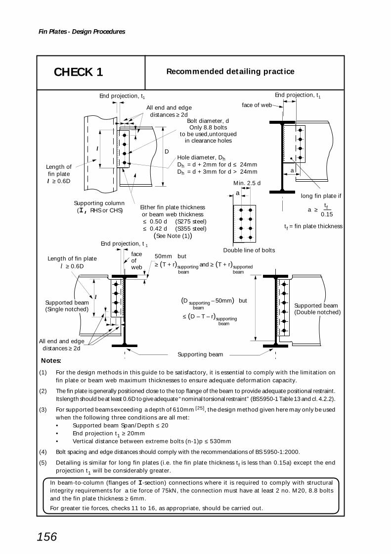
156
Fin Plates - Design Procedures
Notes:
(1) For the design methods in this guide to be satisfactory, it is essential to comply with the limitation onfin plate or beam web maximum thicknesses to ensure adequate deformation capacity.
(2) The fin plate is generally positioned close to the top flange of the beam to provide adequate positional restraint.Its length should be at least 0.6D to give adequate “nominal torsional restraint” (BS 5950-1 Table 13 and cl. 4.2.2).
(3) For supported beams exceeding a depth of 610mm [25], the design method given here may only be usedwhen the following three conditions are all met:• Supported beam Span/Depth ≤ 20• End projection t1 ≥ 20mm• Vertical distance between extreme bolts (n-1)p ≤ 530mm
(4) Bolt spacing and edge distances should comply with the recommendations of BS 5950-1:2000.
(5) Detailing is similar for long fin plates (i.e. the fin plate thickness tf is less than 0.15a) except the endprojection t1 will be considerably greater.
CHECK 1 Recommended detailing practice
Either fin plate thicknessor beam web thickness
≤ 0.50 d (S275 steel) ≤ 0.42 d (S355 steel) (See Note (1))
Length of fin platel ≥ 0.6D
All end and edgedistances ≥ 2d
Hole diameter, DhDh = d + 2mm for d ≤ 24mmDh = d + 3mm for d > 24mm
Length offin platel ≥ 0.6D
All end and edgedistances ≥ 2d
long fin plate if
tf a ≥ –– 0.15
tf = fin plate thickness
(D supporting – 50mm) but
beam
≤ (D – T – r)supportingbeam
50mm but≥ (T + r)supporting and ≥ (T + r)supported
beam beam
End projection, t 1
l
Bolt diameter, dOnly 8.8 bolts
to be used,untorqued in clearance holes
D
End projection, t 1
l
Min. 2.5 d
Supporting column (I, RHS or CHS)
End projection, t
a
Supported beam(Single notched)
Supported beam(Double notched)
Supporting beam
Double line of bolts
a
face of web
face of web
1
In beam-to-column (flanges of I -section) connections where it is required to comply with structuralintegrity requirements for a tie force of 75kN, the connection must have at least 2 no. M20, 8.8 boltsand the fin plate thickness ≥ 6mm.
For greater tie forces, checks 11 to 16, as appropriate, should be carried out.
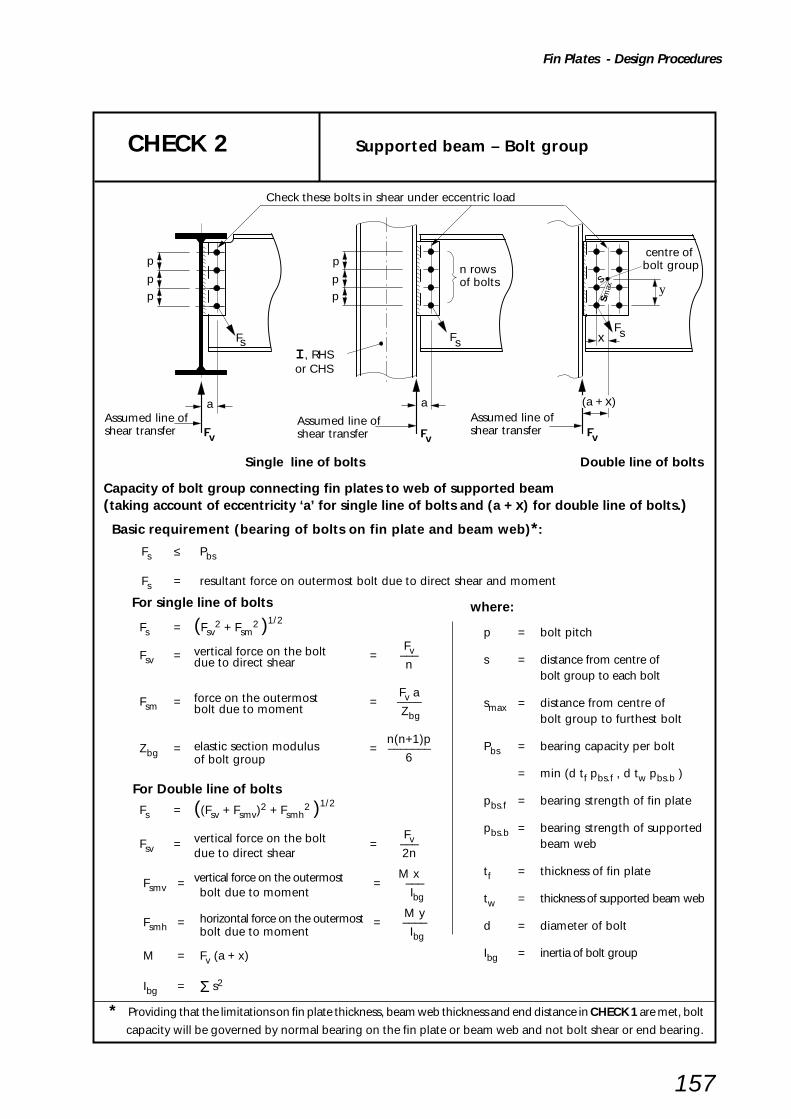
157
Fin Plates - Design Procedures
CHECK 2 Supported beam – Bolt group
Capacity of bolt group connecting fin plates to web of supported beam(taking account of eccentricity ‘a’ for single line of bolts and (a + x) for double line of bolts.)
Basic requirement (bearing of bolts on fin plate and beam web)*:
Fs ≤ Pbs
Fs = resultant force on outermost bolt due to direct shear and moment
For single line of bolts
Fs = (Fsv2 + Fsm
2 )1/2
FvFsv = vertical force on the bolt = –––due to direct shear n
Fv aFsm = force on the outermost = ––––bolt due to moment Zbg
n(n+1)pZbg = elastic section modulus = –––––––
of bolt group 6
For Double line of bolts
Fs = ((Fsv + Fsmv)2 + Fsmh
2 )1/2
vertical force on the bolt FvFsv = = –––due to direct shear 2n
vertical force on the outermost M xFsmv = = –––
bolt due to moment Ibg
M yFsmh = horizontal force on the outermost = ––––
bolt due to moment Ibg
M = Fv (a + x)
Ibg = Σ s2
where:
p = bolt pitch
s = distance from centre ofbolt group to each bolt
smax = distance from centre ofbolt group to furthest bolt
Pbs = bearing capacity per bolt
= min (d tf pbs.f , d tw pbs.b )
pbs.f = bearing strength of fin plate
pbs.b = bearing strength of supportedbeam web
tf = thickness of fin plate
tw = thickness of supported beam web
d = diameter of bolt
Ibg = inertia of bolt group
* Providing that the limitations on fin plate thickness, beam web thickness and end distance in CHECK 1 are met, bolt
capacity will be governed by normal bearing on the fin plate or beam web and not bolt shear or end bearing.
Check these bolts in shear under eccentric load
p
pp
a
n rowsof bolts
Fs
p
pp
aAssumed line ofshear transfer
FsFs
s
max
centre of bolt group
y
xI , RHSor CHS
s
(a + x)
Assumed line ofshear transfer
Single line of bolts Double line of bolts
Assumed line ofshear transferFv Fv Fv

158
Fin Plates - Design Procedures
Shear and bending capacity of fin plate connected to supported beam
(i) For shear:
Basic Requirement:
Fv ≤ Pv.min
Pv.min = shear capacity of fin plate
= smaller of plain shear capacity Pvand block shear capacity Pr
Plain shear
Pv = min (0.6 py Av , 0.7 pyKe Av.net)
Av = 0.9 (2e1 + (n – 1) p) tfAv.net = Av – n Dh tf
Block shear
Pr = 0.6 py tf(Lv + Ke(Lt – kDh ))
Lv = e1 + (n – 1)p
k = 0.5 and Lt = e2 (for single line of bolts)
k = 2.5 and Lt = e2 + gb(for double line of bolts)
(ii) Shear and bending interaction
Basic Requirement:
Fv a ≤ Mc
For low shear (i.e. Fv ≤ 0.75Pv.min)
py tfMc = —— (2e1+(n – 1)p) 2
6
For high shear (i.e. Fv > 0.75Pv.min)
py tf Fv2
1/2
Mc = ——(2e1+(n – 1)p)21 – (——)
4 Pv.min
where:
p = bolt pitch
Dh = hole diameter
tf = fin plate thickness
Ke = 1.2 for S 275 steel
= 1.1 for S 355 steel
CHECK 3 Supported Beam – Connecting elements
a
n rowsof bolts
Single Line of bolts Double Line of bolts
e1
Block shear – check failure by tearing out of shaded portion
e2
Critical section in shear and bending
e1
a
e2gb
e1 e1
Lv
Lt
Lv
LtFv Fv
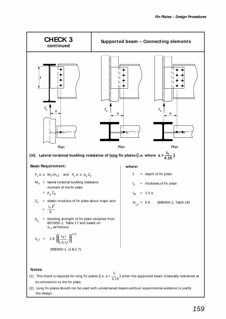
159
Fin Plates - Design Procedures
CHECK 3 Supported beam – Connecting elementscontinued
Basic Requirement:
Fv a ≤ Mb/mLT and Fv a ≤ py Zx
Mb = lateral torsional buckling resistance
moment of the fin plate
= pb Zx
Zx = elastic modulus of fin plate about major axis
tf l2
= —— 6
pb
= bending strength of fin plate obtained fromBS 5950-1, Table 17 and based onλLT as follows:
LE l 1/2
λLT = 2.8 –––– 1.5 tf
2
(BS5950-1, cl.B.2.7)
a
Plan
a
Plan
a
Plan
l
Fv Fv Fv
tf (iii) Lateral torsional buckling resistance of long fin plates (i.e. where a > –––– ) 0.15
where:
l = depth of fin plate
tf = thickness of fin plate
LE = 1.0 a
mLT
= 0.6 (BS5950-1, Table 18)
Notes: tf
(1) This check is required for long fin plates (i.e. a > — ) when the supported beam is laterally restrained at 0.15
its connection to the fin plate.
(2) Long fin plates should not be used with unrestrained beams without experimental evidence to justify
the design.

160
Fin Plates - Design Procedures
CHECK 4 Supported Beam – Capacity at the connection
(i) For shear:
Basic requirement:Fv ≤ Pv.min
Pv.min = shear capacity of the beamat the connection
= smaller of:Plain shear capacity Pv andBlock shear capacity Pr
Plain shear:Pv = min (0.6 py Av , 0.7 pyKe Av.net)Av = (et + (n – 1) p + eb)tw
(for un-notched and single notch beam)
= 0.9(et + (n–1)p + eb)tw(for double notched beam)
Av.net = Av – n Dh tw
Shear and bending capacity of the supported beam:
Block shear (applicable to notch beams only)
Pr = 0.6 py tw(Lv + Ke(Lt – kDh ))
Lv = et + (n – 1)p
k = 0.5 and Lt = e3 (for single line of bolts)
k = 2.5 and Lt = e3 + gb (for double line of bolts)
where:Ke = 1.2 for S 275 steel
1.1 for S 355 steel
p = boIt pitch
Dh = diameter of hole
tw = thickness of supported beam web
Critical section in plain shear
Block shear failuretearing out of shaded portion
e t e t e t
eb ebeb
e t e t
eb eb
Critical section in plain shear
e3
n rowsof bolts
e3 gb
e3 e3
e3 b
Block shear failuretearing out of shaded portion
n rowsof bolts
e t
eb
e3 gbgt1 t1 t1
t1 t1 t1
Fv FvFv
Fv FvFv
Shear failure
Lt
Lv
Tension failure
Lt
Shear failure
Tension failure
Lt
Lt
Tension failure
Shear failure
Shear failure
Tension failure
Lv

161
Fin Plates - Design Procedures
CHECK 4 Supported beam – Capacity at the connectioncontinued
(ii) Shear and Bending interaction at the 2nd line of bolts, if the notch length c > (e3 + gb)
Basic requirement:
Fv (t1 + e3 + gb) ≤ McC
For single notched beam:For low shear (i.e. Fv ≤ 0.75Pv.min)
McC = py Z
For high shear (i.e. Fv > 0.75Pv.min)
Fv2
1/2
McC = 1.5 pyZ 1 – ( –––– ) Pv.min
.....
For double notched beam:For low shear (i.e. Fv ≤ 0.75Pv.min)
pytwMcC = ____ (et + (n-1)p + eb)2
6
For high shear (i.e. Fv > 0.75Pv.min)
pytw 2 Fv 2 1/2
McC = ____ (et + (n–1)p + eb) 1 – (____ )
4 Pv.min .....
Note: If the notch length c is greater than (e3 + gb), then shear and bending interaction should be checkedat the 2nd line of bolts. The beam at the end of the notch may also be critical - see CHECK 5.
e t
eb
Critical section for shear and bending interaction
e3 b
e t
eb
e3 gbgt1 t1
n rowsof bolts
Fv Fv
cc c
where:
McC = moment capacity of the notched
beam at the connection in the
presence of shear.
Z = elastic section modulus of the
gross tee section at the bolt line.
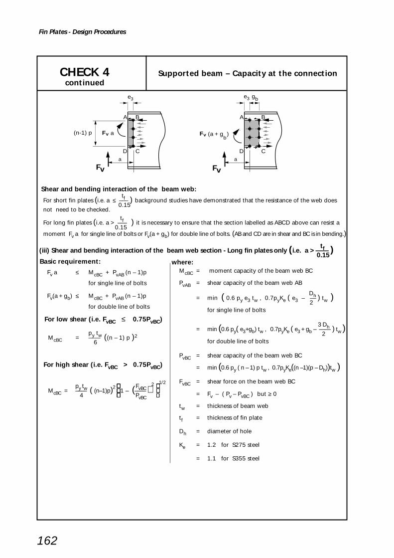
162
Fin Plates - Design Procedures
CHECK 4 Supported beam – Capacity at the connectioncontinued
Shear and bending interaction of the beam web:
Basic requirement:
Fv a ≤ McBC + PvAB (n – 1)p
for single line of bolts
Fv(a + gb) ≤ McBC + PvAB (n – 1)p
for double line of bolts
For low shear (i.e. FvBC ≤ 0.75PvBC)
py twMcBC = —— ((n – 1) p )2 6
For high shear (i.e. FvBC > 0.75PvBC)
py tw FvBC2
1/2
McBC = –––– ( (n–1)p)2 1 – (–––– )
4 PvBC
tfFor short fin plates (i.e. a ≤ ––– ) background studies have demonstrated that the resistance of the web does 0.15
not need to be checked. tfFor long fin plates (i.e. a > ––– ) it is necessary to ensure that the section labelled as ABCD above can resist a 0.15
moment Fv a for single line of bolts or Fv(a + gb) for double line of bolts. (AB and CD are in shear and BC is in bending.)
tf (iii) Shear and bending interaction of the beam web section - Long fin plates only (i.e. a > —— ) 0.15
where:McBC = moment capacity of the beam web BC
PvAB = shear capacity of the beam web AB
Dh= min ( 0.6 py e3 tw , 0.7pyKe ( e3 – –– ) tw ) 2
for single line of bolts
3 Dh= min (0.6 py( e3+gb) tw , 0.7pyKe ( e3 + gb – —— ) tw )2for double line of bolts
PvBC = shear capacity of the beam web BC
= min (0.6 py ( n – 1) p tw , 0.7pyKe((n –1)(p – Dh))tw )
FvBC = shear force on the beam web BC
= Fv – ( Pv – PvBC ) but ≥ 0
tw = thickness of beam web
tf = thickness of fin plate
Dh = diameter of hole
Ke = 1.2 for S275 steel
= 1.1 for S355 steel
D C
A B
a
D C
A B
(a + g )(n-1) pb
a a
e3 e3 gb
Fv Fv
Fv Fv

163
Fin Plates - Design Procedures
CHECK 5 Supported beam – Capacity at a notch
t c1
Critical sections
t c1 t c1
e t
eb
n rowsof bolts
e t
eb
e t
eb
to notch or beam flange
t c1
e t
eb
Fv Fv Fv Fv xN xN
Basic requirement:
(a) For single bolt line or for double bolt lines, if xN ≥ 2d:
Fv (t1 + c) ≤ McN
McN for Single notched beam:
For low shear (i.e. Fv ≤ 0.75PvN)
McN = pyZN
For high shear (i.e. Fv > 0.75PvN)
Fv 1/2
McN = 1.5pyZN 1 – ( ___ )2
PvN .....
McN for Double notched beam:
For low shear (i.e. Fv ≤ 0.75PvN)
pytwMcN = ____ (et + (n–1)p + eb)
2
6
For high shear (i.e. Fv > 0.75PvN)
pytw 2 Fv 2 1/2
McN = ____ (et + (n–1)p + eb) 1 – (____ ) 4 PvN .....
(b) For Double bolt lines, if xN < 2d:
max ( Fv(t1+c), Fv(t1+e3+gb)) ≤ McN
McN = McC from Check 4
Shear and bending interaction at the notch:
where:McN = moment capacity of the beam at the
notch in the presence of shear
PvN = shear capacity at the notch
= 0.6 py AvN
AvN = (et + (n – 1) p + eb)tw
(for single notched beam)
= 0.9(et + (n – 1) p + eb)tw
(for double notch beam)
t1 = end projection
tw = thickness of supported beam web
c = length of notch
ZN = elastic section modulus of the gross tee
section at the notch
e3 , gb as per CHECK 4
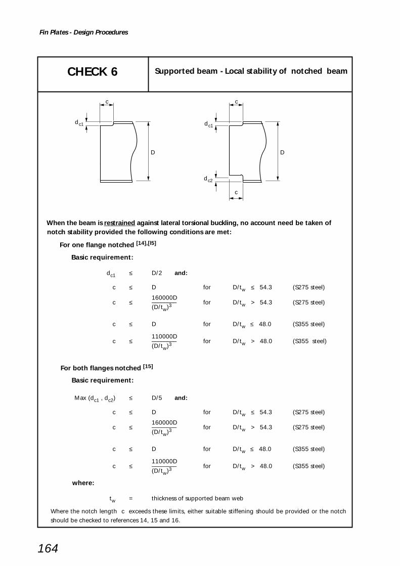
164
Fin Plates - Design Procedures
D
c
D
c
c
dc1dc1
dc2
CHECK 6 Supported beam - Local stability of notched beam
When the beam is restrained against lateral torsional buckling, no account need be taken of notch stability provided the following conditions are met:
For one flange notched [14],[l5]
Basic requirement:
dc1 ≤ D/2 and:
c ≤ D for D/tw ≤ 54.3 (S275 steel)
160000Dc ≤ –––––––– for D/tw > 54.3 (S275 steel)
(D/tw)3
c ≤ D for D/tw ≤ 48.0 (S355 steel)
110000Dc ≤ –––––––– for D/tw > 48.0 (S355 steel)
(D/tw)3
For both flanges notched [15]
Basic requirement:
Max (dc1 , dc2) ≤ D/5 and:
c ≤ D for D/tw ≤ 54.3 (S275 steel)
160000Dc ≤ –––––––– for D/tw > 54.3 (S275 steel)
(D/tw)3
c ≤ D for D/tw ≤ 48.0 (S355 steel)
110000Dc ≤ –––––––– for D/tw > 48.0 (S355 steel)
(D/tw)3
where:
tw = thickness of supported beam web
Where the notch length c exceeds these limits, either suitable stiffening should be provided or the notch
should be checked to references 14, 15 and 16.

165
Fin Plates - Design Procedures
CHECK 7 Unrestrained Supported BeamOverall stability of notched beam
c
D
b
c
L
dc1dc1
When a notched beam is unrestrained against lateral torsional buckling, the overallstability of the beam should be checked.
Notes:
(1) This check is only applicable for beams with one flange notched. Guidance on double-notched
beams is given in Section 5.12 of Reference 17.
(2) If the notch length c and/or notch depth dc1 are different at each end, then the larger values for
c and dc1 should be used.
(3) Beams should be checked for lateral torsional buckling to BS 5950-1[1], clause 4.3 with a
modified effective length (LE) which takes account of notches.
(4) The solution below gives the modified effective length (LE) based on references 18, 19 and 20.
It is only valid for c /Lb < 0.15 and dc1/D < 0.2 (beams with notches outside these limits should
be checked as tee sections, or stiffened).
2c 1/2
LE = Lb 1 + –– (K2 + 2K) Lb
K = Ko/λb
u v Lbλb = –––––– ry
where: x, u, v and ry are for the un-notched I beam section and are defined in BS 5950-1
Conservatively, u = 0.9 and v = 1.0
for λb < 30 Ko = 1.1 go x but ≤ 1.1 Kmax
for λb ≥ 30 Ko = go x but ≤ Kmax
go and Kmax are tabulated below:
c
Kmax ––
go UB UC Lb
section section
≤ 0.025 5.56 260 70
0.050 5.88 280 80
0.075 6.19 290 90
0.100 6.50 300 95
0.125 6.81 305 95
0.150 7.13 315 100

166
Fin Plates - Design Procedures
CHECK 8 Supporting beam/Column – Welds
Strength of weld connecting fin plate to supporting beam or columnunder bending moment and shear
CHECK 9 Not applicable (see Table 3.1)
sts
Critical weld
I web or flange or RHS, CHS wall
Critical weld
f
Supporting beam Supporting column
Basic requirement:
s ≥ 0.8tf
where:
s = leg length of fillet weld
tf = fin plate thickness
Note: This check ensures that the weld is not the weakest part of the connection.

167
Fin Plates - Design Procedures
Local shear and punching shear capacity of :- beam web supporting one beam- web of I column supporting one beam- wall of RHS or CHS column supporting one beam
(i) Local shear capacity: Basic requirement: Fv –– ≤ Pv 2
Pv = local shear capacity of supportingbeam web or column web or column wall
= 0.6 py Av
Av = 0.9 l tw
(ii) Punching shear capacity:Provided that either the conservative or rigorousrequirement given below is satified, yielding of the finplate occurs before punching shear failure of thesupporting member:
Basic requirement (either will suffice):
Usc tf ≤ tw –––– OR
pyf
(Conservative)
Usc tf ≤ tw ––––
fb
(Rigorous)
where:
tw = thickness of supporting beam web,column web or column wall
tf = fin plate thickness
Usc = Ultimate tensile strength ofsupporting member
pyf = design strength of fin plate
fb = maximum bending stress in the finplate
Fv a= –––– but fb ≤ pyfZgross
Zgross = elastic modulus of gross section ofthe fin plate
tf l
2
= ––––6
CHECK 10 Supporting beam/column - Local capacity(with one supported beam)
l
Supporting beam
w
RHS Column
wtwall thickness
CHS Column
wtwall thicknessweb thickness
I Columna
a
t
wtFv Fv
Fv Fv
l

168
Fin Plates - Design Procedures
(iii) Local shear capacity of supporting beam web or column web supporting two beams:
CHECK 10 Supporting beam/column - Local capacity continued (with two supported beams)
l1
Supporting beam
l2
wt
Supporting column web
1Fv2Fv
2Fv 1Fv
Basic Requirement:
Fv1A Fv2––– + –– ≤ Pv2 2
where: l2Fv1A = Fv1 –– l1
Pv = local shear capacity of supportingbeam web or column web
= 0.6 py Av
Av = 0.9 l2 tw
tw = thickness of supporting beam webor column web

169
Fin Plates - Design Procedures
CHECK 11 Structural integrity - connecting elements
(i) For tension:
Basic requirement:
Tie force ≤ Tension capacity of fin plate
Tension capacity of fin plate
= min (py A , Ke py Anet )
A = l tf
Anet = A – nDhtf
(ii) For bearing:
Basic requirement:
Tie force ≤ Bearing capacity of fin plate
Bearing capacity of fin plate
= 1.5n d tf pbs but
≤ 0.5n e2 tf pbs
(for single line of bolts)
= 3n d tf pbs but
≤ n (1.5d t f pbs + 0.5 e2 tf pbs )(for double lines of bolts)
n rowsof bolts
Tie force Tie force
gb
Single line of bolts Double line of bolts
e2e2
e1
e1
p
p
p
l
Note: This check is only needed if it is necessary to comply with structural integrity requirements.
To resist a tie force of 75kN, the connection must have at least 2 no. M20, 8,8 bolts and a fin plate
thickness ≥ 6mm.
Structural integrity – tension and bearing capacity of fin plate
where:
p = bolt pitch
d = diameter of bolt
Dh = diameter of hole
tf = thickness of fin plate
pbs = bearing strength of the plate
( BS 5950-1, Table 32)
Ke = 1.2 for S275 steel
1.1 for S355 steel

170
Fin Plates - Design Procedures
CHECK 12 Structural Integrity – supported beam
Note: This check is only needed if it is necessary to comply with structural integrity requirements
Structural integrity – tension and bearing capacity of beam web
(i) For tension Basic requirement:
Tie force ≤ Net tension capacity of beam web
Net tension capacity of beam web
= Le tw py
(ii) For bearing
Basic requirement:
Tie force ≤ Bearing capacity of beam web.
Bearing capacity of beam web
= 1.5n d t w pbs but
≤ 0.5ne3tw pbs
for single line of bolts
= 3n d t w pbs but
≤ n(1.5d t w pbs + 0.5 e3 twpbs )for double line of bolts
where: Le = effective net length
= 2ee + (n – 1)pe – nDh
ee = e3 but ≤ et for single line of bolts
ee = e3 + gb – Dh but ≤ et for double line of bolts
pe = p but ≤ 2e3 for single line of bolts
pe = p but ≤ 2(e3 + gb – Dh) for double line of bolts
tw = beam web thickness
p = bolt pitch
Dh = diameter of hole
d = diameter of bolt
pbs = bearing strength of beam web(BS 5950–1, Table 32)
n rowsof bolts
et
p
p
p
n rowsof bolts
et
p
p
p
et
Tie force Tie force
Tie force Tie force
et
gb
bg
e3 e3
e3e3
CHECK 13 Not applicable (see Table 3.1)

171
Fin Plates - Design Procedures
Tie Force
t + 2s
l
f
dc
Fin plate connecting to column web
ft
CHECK 14 Structural integrity – Supporting column web (UC or UB)
Basic requirement:
Tie force ≤ Tying capacity of column web
Tying capacity 8 Mu= ––––– (η
1 + 1.5(1 – β1)0.5) *of column web 1 – β 1
Mu = moment capacity of column
web per unit length
pu tw2
= –––––– 4
pu = design tensile strength of the column
= Us /1.25 (see inset box)
* Factor 1.5 in the equation includes an
allowance for the axial compression
in the column
Design tensile strength
pu = Us /1.25
S275 328 N/mm2
S355 392 N/mm2
Values of Us taken from BS EN 10025: 1993[21]
This check is only needed if it is necessary to comply with structural integrity requirements
Structural integrity – Tying capacity of rolled column web, in the presence of axial compression inthe column
where:
lη1 = –––
dc
tf + 2sβ1 = –––––
dc
tf = thickness of fin plate
l = length of fin plate
d c = depth of column between fillets
tw = thickness of column web
s = leg length of weld
Note: The check is required for either single-sided connections to the rolled column webor unequally loaded double-sided connections to the rolled column web.

172
Fin Plates - Design Procedures
CHECK 15 Structural integrity –supporting column wall (RHS)
( )
Tie Force
l
t
B
yield lines
w
1.5t w
Fin plate connecting to RHS column
t + 2sf
ft
This check is only needed if it is necessary to comply with structural integrity requirements
Structural integrity – Tying capacity of RHS wall, in the presence of axial compression in thecolumn
Basic requirement:
Tie force ≤ Tying capacity of RHS column wall
Tying capacity 8 Mu= ––––– (η
+ 1.5(1 – β)0.5) * RHS column wall 1 – β
Mu = moment capacity of RHS column
wall per unit length
pu tw2
= –––––– 4
pu = design tensile strength of the RHS column
= Us /1.25 (see inset box)
* Factor 1.5 in the equation includes an
allowance for the axial compression
in the column
Design tensile strength
pu = Us /1.25
S275 328 N/mm2
S355 392 N/mm2
Values of Us taken fromBS EN 10201 - 1:1994[3]
where:
l η = –––––––
(B – 3tw)
(tf + 2s) β = –––––––
(B – 3tw)
tf = thickness of fin plate
l = length of fin plate
B = overall width of RHS column wall
to which the connection is made
tw = thickness of RHS column wall
s = leg length of weld
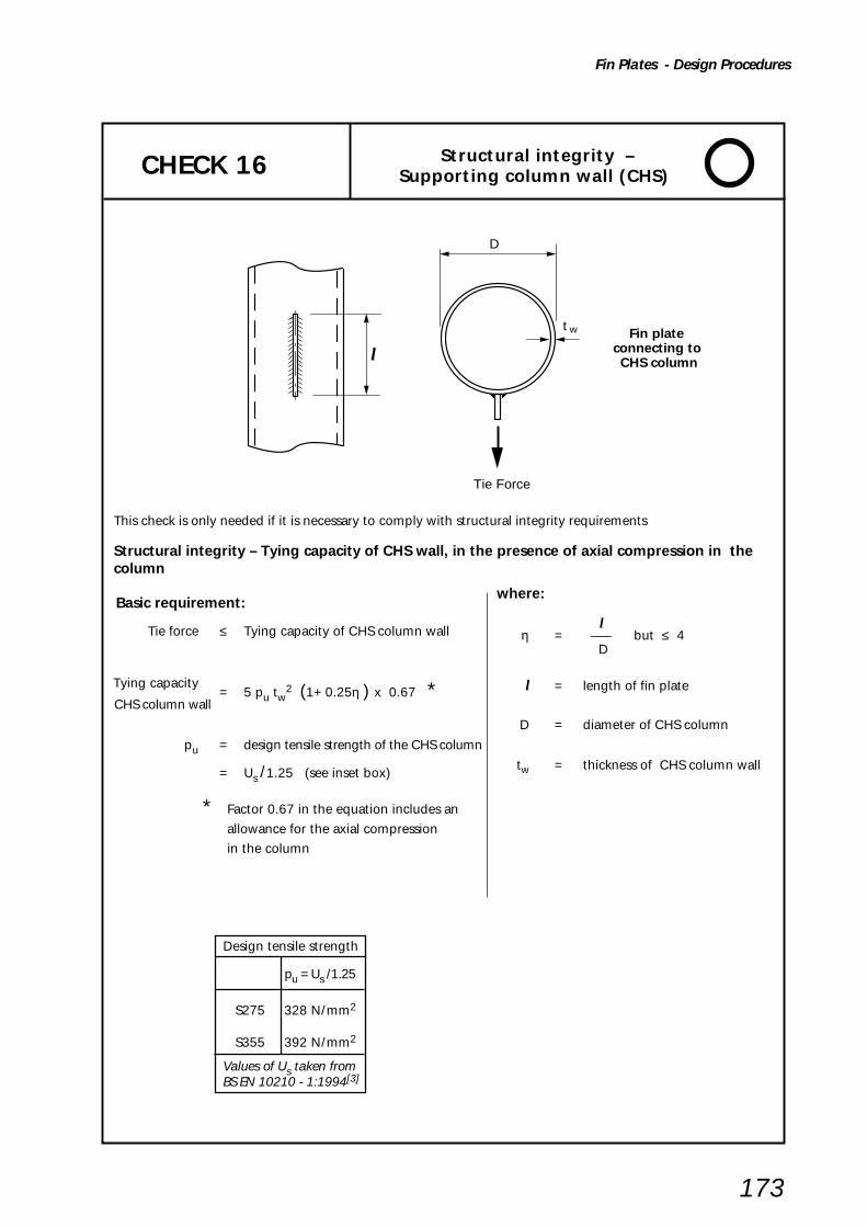
173
Fin Plates - Design Procedures
CHECK 16 Structural integrity –Supporting column wall (CHS)
This check is only needed if it is necessary to comply with structural integrity requirements
Structural integrity – Tying capacity of CHS wall, in the presence of axial compression in thecolumn
Basic requirement:
Tie force ≤ Tying capacity of CHS column wall
Tying capacity= 5 pu tw
2 (1+ 0.25η ) x 0.67 * CHS column wall
pu = design tensile strength of the CHS column
= Us /1.25 (see inset box)
* Factor 0.67 in the equation includes an
allowance for the axial compression
in the column
Design tensile strength
pu = Us /1.25
S275 328 N/mm2
S355 392 N/mm2
Values of Us taken fromBS EN 10210 - 1:1994[3]
where:
l η = ––– but ≤ 4
D
l = length of fin plate
D = diameter of CHS column
tw = thickness of CHS column wall
Tie Force
l
D
Fin plate connecting to CHS column
t w

174
Fin Plates - Worked Examples
6.6 WORKED EXAMPLES
The worked examples show design calculations for typicalstandard connections. Each example demonstrates firstthe use of the capacity tables (yellow pages) and then fullchecks according to the procedures in Section 6.5. The fullchecks will normally only need to be applied to non-standard connections but their application to standardconnections demonstrates the validity of the much simplerprocess when using standard details.
Check 7, dealing with overall stability of an unrestrainedbeam, should be undertaken by the member designertaking account of any notching required at the ends of thesupported beam in order to facilitate the use of a simpleconnection.
Checks 11 to 15 deal with structural integrity in thepresence of an axial tie force required to be developed insome members to ensure the steel frame is sufficientlyrobust, or in the case of some multi-storey buildings, tolocalise accidental damage. When tying capacity is notrequired these checks may be omitted.
Example 1
This example covers the design checks for a two sidedbeam-to-beam connection with fin plates welded to theweb only of the supporting beam. A fin plate with a singleline of vertical bolts is employed on one side and anotherwith a double line of bolts is used to connect a largerbeam, with a heavier vertical reaction, on the other side.
Example 2
Example 2 demonstrates the additional structuralintegrity design checks required for a beam-to-columnweb connection when an axial tie force must be sustainedby the connection.
Example 3
Example 3 is a beam-to-RHS column connection usingfin plates welded to the column wall. The beam sizes andvertical reactions as in Example 1, so only checks whichare different to the those in the first example are shown.
The connection design also considers tie forces in thebeams but it should be noted that the tie forces areignored in checks for vertical reactions and vertical reactionsare ignored in checks for tie forces.
Example 4
Example 4 shows the same beam connections as inExample 3 but uses fin plates welded to a CHS column. Tieforces are taken into account separately from the verticalreactions.

Example 1 – Fin Plates - Beam to BeamSheetTitle
Fin Plates - Worked Example 1
175
BCSA
CALCULATIONSHEET
Calcs by
Title
Client
Checked by Date
Job No SheetJoints in Steel Construction - Simple Connections
Example 1 – Fin Plates - Beam to Beam
SCI/BCSA Connections Group
RS AM May 2002
1 of 12
DESIGN EXAMPLE 1
Check the following beam to beam connection for the design forces shown.
Yellow pages used for the initial selection of Fin Plates.
A fin plate with a single vertical line of bolts would be adequate for both connections in thisexample, but a double vertical line was used for the 533 x 229 x 92 UB in order to demonstratethe design checks required for this configuration.
See Figure 6.4
Fin Plates: 100 x 10 150 x 10(Single line Type FA4) (Double line Type FB5)
Design Information:Bolts: M20 8.8
Welds: 8mm Fillet WeldMaterial: All S275
See figure 6.4 andYellow pagesTable H.4
50 Notch
40
70
70
70
7040
40
N = 120
533 x 210 x 92 UBGrade S275
406 x 178 x 74 UBGrade S275
610 x 229 x 140 UBGrade S275
350 kN200 kN
50 75
End projection10mm
8

Example 1 – Fin Plates - Beam to BeamSheetTitle
Fin Plates - Worked Example 1
176
CONNECTION DESIGN USING CAPACITY TABLES FROM YELLOW PAGES
Fin Plate type FA4 Grade S275 Fin Plate type FB5 Grade S275
Bolts M20 8.8 Bolts M20 8.8
From capacity table H.27 in From capacity table H.28 inyellow pages: yellow pages:
Connection shear capacity Connection shear capacity= 265kN > 200kN = 476kN > 350kN ∴ O.K.
Maximum notch length (c + t1) Maximum notch length (c + t1)= 336mm > 120mm = 345mm > 120mm ∴ O.K.
Web thickness of supporting beam = 13.1mm Table H.64
Minimum support thickness based on the maximum shears of 265kN and 476kN = (6.2 + 8.2) = 14.4mm |< 13.1mm ∴ Fails
but for shear forces of 200kN and 350 kN the minimum required thickness
200 350 = 6.2 x ––– + 8.2 x –––
265 476
= 4.7mm + 6.0mm
= 10.7mm < 13.1mm ∴ ∴ ∴ ∴ ∴ O.K.
The connections are adequate.
2 of 12
533 x 210 x 92 UBGrade S275
406 x 178 x 74 UBGrade S275
610 x 229 x 140 UBGrade S275
350 kN200 kN
Yellow pagesTable H.27and H.28
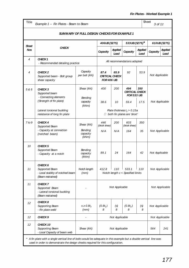
Example 1 – Fin Plates - Beam to BeamSheetTitle
Fin Plates - Worked Example 1
177
3 of 12
SUMMARY OF FULL DESIGN CHECKS FOR EXAMPLE 1
* A fin plate with a single vertical line of bolts would be adequate in this example but a double vertical line was used in order to demonstrate the design checks required for this configuration.
406UB (S275) 533UB (S275)* 610UB (S275)Sheet
CHECKNos
CapacityApplied
CapacityApplied
CapacityApplied
Load Load Load
4 CHECK 1 - Recommended detailing practice
All recommendations adopted
4 CHECK 2 Capacity 87.4 65.9 92 53.9 Not ApplicableSupported beam - Bolt group per bolt (kN) CRITICAL CHECK
shear capacity FOR 406 UB
5 & 6 CHECK 3 Shear (kN) 400 200 494 350
Supported beam
Bending
CRITICAL CHECK
- Connecting elements
capacity
FOR 533 UB
Not Applicable(Strength of fin plate) (kNm)
38.6 10 59.4 17.5
Lateral torsional buckling Plate thickness tf > 0.15aresistance of long fin plate ∴ both fin plates are 'short'
7 to 9 CHECK 4 446 200 603 350Supported Beam
Shear (kN) (block shear) (block shear)
Not Applicable- Capacity at connection Bending N/A N/A 164 35(notched beam) capacity
(kNm)
10 CHECK 5Supported Beam Bending
89.1 24 164 42
Not Applicable- Capacity at a notch capacity(kNm)
CHECK 611 Supported Beam Notch length 412.8 110 533.1 110 Not Applicable
- Local stablity of notched beam (mm) Notch length c < Specified limits(Beam restrained)
11 CHECK 7Supported Beam - Not Applicable
Not Applicable
- Lateral torsional buckling(Beam restrained)
12 CHECK 8 s ≥ 0.8tf (0.8tf ) (s) (0.8tf ) (s)Supporting Beam(mm) 8 8 8 8
Not Applicable- Fin plate weld
12 CHECK 9 - Not Applicable Not Applicable
12 CHECK 10Supporting Beam Shear (kN) Not Applicable 564 241- Local Capacity of beam web
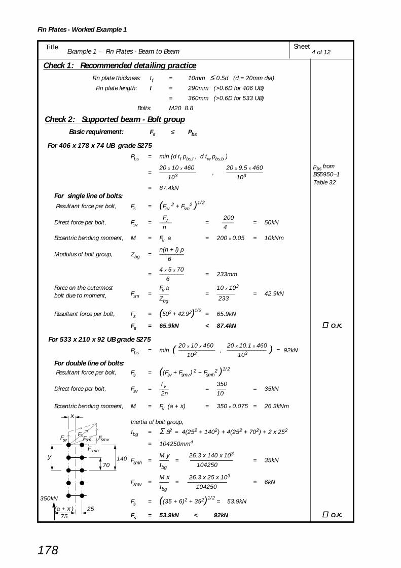
Example 1 – Fin Plates - Beam to BeamSheetTitle
Fin Plates - Worked Example 1
178
4 of 12
Check 1: Recommended detailing practiceFin plate thickness: tf = 10mm ≤ 0.5d (d = 20mm dia)
Fin plate length: l = 290mm (>0.6D for 406 UB)
= 360mm (>0.6D for 533 UB)
Bolts: M20 8.8
Check 2: Supported beam - Bolt group Basic requirement: Fs ≤ Pbs
For 406 x 178 x 74 UB grade S275
Pbs = min (d tf pbs.f , d tw pbs.b )
20 x 10 x 460 20 x 9.5 x 460= –––––––––––– , ––––––––––––
103 103
= 87.4kNFor single line of bolts: Resultant force per bolt, Fs = (Fsv
2 + Fsm2 )1/2
Fv 200Direct force per bolt, Fsv = –––– = –––– = 50kN
n 4
Eccentric bending moment, M = Fv a = 200 x 0.05 = 10kNm
n(n + l) pModulus of bolt group, Zbg = ––––––––
6
4 x 5 x 70= –––––––– = 233mm
6Force on the outermost Fv a 10 x 103
bolt due to moment, Fsm = ––– = –––––– = 42.9kNZbg 233
Resultant force per bolt, Fs = (502 + 42.92)1/2 = 65.9kN
Fs = 65.9kN < 87.4kN ∴ ∴ ∴ ∴ ∴ O.K.
For 533 x 210 x 92 UB grade S27520 x 10 x 460 20 x 10.1 x 460
Pbs = min ( –––––––––––– , ––––––––––––– ) = 92kN 103 103
For double line of bolts: Resultant force per bolt, Fs = ((Fsv + Fsmv ) 2 + Fsmh
2 )1/2
Fv 350Direct force per bolt, Fsv = ––– = ––– = 35kN
2n 10
Eccentric bending moment, M = Fv (a + x) = 350 x 0.075 = 26.3kNm
Inertia of bolt group,
Ibg = Σ S2 = 4(252 + 1402) + 4(252 + 702) + 2 x 252
= 104250mm4
M y 26.3 x 140 x 103Fsmh = ––– = –––––––––––––– = 35kN
Ibg 104250
M x 26.3 x 25 x 103Fsmv = ––– = ––––––––––––– = 6kN
Ibg 104250
Fs = ((35 + 6)2 + 352)1/2 = 53.9kN
Fs = 53.9kN < 92kN ∴ ∴ ∴ ∴ ∴ O.K.
350kN
(a + x )75
25
y70
140
x
F
F
Fsv
smh
smvF smF s
pbs fromBS5950–1Table 32
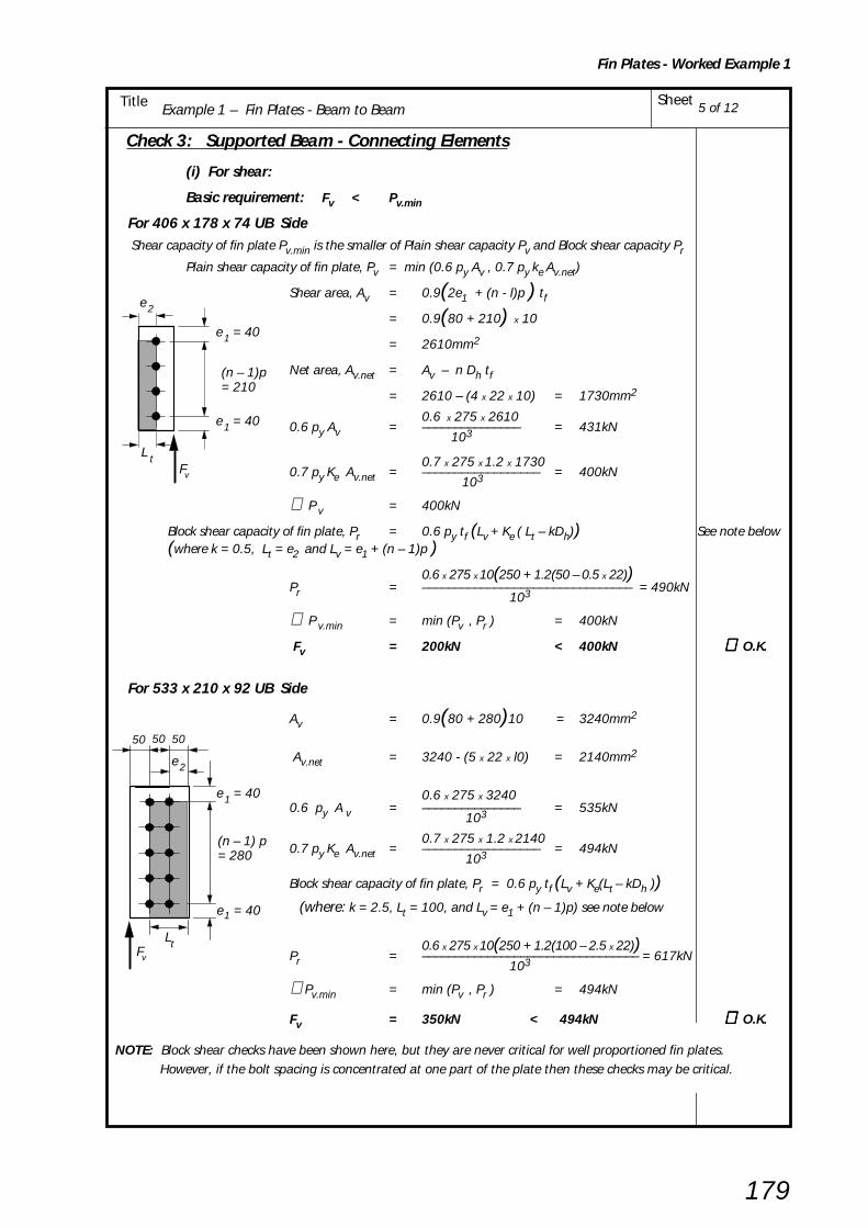
Example 1 – Fin Plates - Beam to BeamSheetTitle
Fin Plates - Worked Example 1
179
5 of 12
Check 3: Supported Beam - Connecting Elements
(i) For shear:
Basic requirement: Fv < Pv.min
For 406 x 178 x 74 UB Side Shear capacity of fin plate Pv.min is the smaller of Plain shear capacity Pv and Block shear capacity Pr
Plain shear capacity of fin plate, Pv = min (0.6 py Av , 0.7 py ke Av.net)
Shear area, Av = 0.9(2e1 + (n - l)p ) tf
= 0.9(80 + 210) x 10
= 2610mm2
Net area, Av.net = Av – n Dh tf
= 2610 – (4 x 22 x 10) = 1730mm2
0.6 x 275 x 26100.6 py Av = ––––––––––––––– = 431kN
103
0.7 x 275 x 1.2 x 17300.7 py Ke Av.net = –––––––––––––––––– = 400kN
103
∴ P v = 400kN
Block shear capacity of fin plate, Pr = 0.6 py tf (Lv + Ke ( Lt – kDh)) See note below (where k = 0.5, Lt = e2 and Lv = e1 + (n – 1)p )
0.6 x 275 x 10(250 + 1.2(50 – 0.5 x 22))Pr = –––––––––––––––––––––––––––––––– = 490kN
103
∴ P v.min = min (Pv , Pr ) = 400kN
Fv = 200kN < 400kN ∴∴∴∴∴ O.K.
For 533 x 210 x 92 UB Side
Av = 0.9(80 + 280)10 = 3240mm2
Av.net = 3240 - (5 x 22 x l0) = 2140mm2
0.6 x 275 x 32400.6 py A v = ––––––––––––––– = 535kN
103
0.7 x 275 x 1.2 x 21400.7 py Ke Av.net = –––––––––––––––––– = 494kN
103
Block shear capacity of fin plate, Pr = 0.6 py tf (Lv + Ke(Lt – kDh )) (where: k = 2.5, Lt = 100, and Lv = e1 + (n – 1)p) see note below
0.6 x 275 x 10(250 + 1.2(100 – 2.5 x 22))Pr = ––––––––––––––––––––––––––––––––– = 617kN
103
∴Pv.min = min (Pv , Pr ) = 494kN
Fv = 350kN < 494kN ∴∴∴∴∴ O.K.
NOTE: Block shear checks have been shown here, but they are never critical for well proportioned fin plates. However, if the bolt spacing is concentrated at one part of the plate then these checks may be critical.
(n – 1)p= 210
Fv
e 2
L t
e = 401
e = 401
e = 401
(n – 1) p= 280
e = 401
Fv
Lt
e 2
505050

Example 1 – Fin Plates - Beam to BeamSheetTitle
Fin Plates - Worked Example 1
180
6 of 12
= 200kN
a = 50
10
290
Fv
e = 401
10
= 350kN
a = 50 50
360
Fv
e = 401
(ii) Basic requirement for shear and bending interaction:
Fv a ≤≤≤≤≤ Mc
For 406 x 178 x 74 UB Side0.75 Pv.min = 0.75 x 400 = 300kN
Fv = 200kN < 300kN
∴ low shear criteria for bending applies
py tf∴∴∴∴∴ Mc = –––– (2e1+(n – 1)p) 2
6
275 x 10= ––––––––(2 x 40 + 210)
2
6 x 106
= 38.6kNm
Eccentric moment, Fv a = 200 x 0.05 = 10kNm
Fv a = 10kNm < 38.6kNm ∴∴∴∴∴ O.K.
For 533 x 210 x 92 UB Side
0.75 Pv.min = 0.75 x 494 = 371kN
Fv = 350kN < 371kN
∴ low shear criteria for bending applies
275 x 10 ∴∴∴∴∴ Mc = ––––––––(2 x 40 + 280)
2
6 x 106
= 59.4kNm
Eccentric moment Fv a = 350 x 0.05 = 17.5kNm
Fv a = 17.5kNm < 59.4kNm ∴∴∴∴∴ O.K.
(iii) Lateral Torsional Buckling Resistance of Long Fin Plates: This check is only required where tf < 0.15a
For 406 x178 x 74 UB and 533 x 210 x 92 UB:
0.15a = 0.15 x 50
= 7.5mm
tf = 10mm ∴ Lateral Torsional Buckling check not required
Note: For a double vertical line of bolts the eccentricity is taken from the support to the first vertical line of bolts.

Example 1 – Fin Plates - Beam to BeamSheetTitle
Fin Plates - Worked Example 1
181
7 of 12
Check 4: Supported Beam - Capacity at the connection
(i) Basic requirement for shear: Fv ≤ Pv.min
where Pv.min is the smaller of the plain shear capacity, Pv or the block shear capacity, Pvof the supported beam
For 406 x 178 x 74 UB grade S275
Plain shear capacity, Pv = min ( 0.6 py A v , 0.7 py Ke Av.net )
Av = (et + (n – 1) p + eb )twfor single notched/plain beam
Av = (40 + 210 + 113) x 9.5
= 3449mm2
Av.net = Av – n Dh tw
= 3449 – (4 x 22 x 9.5)
= 2613mm2
0.6 x 275 x 34490.6 py Av = –––––––––––––– = 569kN
103
0.7 x 275 x 1.2 x 26130.7 py Ke Av.net = ––––––––––––––––––– = 604kN
103
∴ Pv = 569kN
Block shear capacity, Pr = 0.6 py t w (Lv + Ke ( Lt – kDh ))
Lv = et + (n – 1)p
= 40 + 210
= 250mm
Ke = 1.2 ( for S275 steel )
k = 0.5 ( for single line of bolts )
Lt = e3 ( for single line of bolts )
0.6 x 275 x 9.5(250 + 1.2(40 – 11))∴ Pr = ––––––––––––––––––––––––––––––– 103
= 446kN
Shear capacity of supported beam Pv.min = min (Pv , Pr ) = 446kN
Applied shear Fv = 200kN < 446kN ∴∴∴∴∴ O.K.
t = 9.5w
e = 40
(n - 1)p = 210
e = 113
t
b
Shear plane
Bolt diameter,d = 20mm
Hole diameter,D = 22mmh
t = 9.5w
e = 40
(n - 1)p = 210
e = 113
t
b
Block shear failure
e = 403

Example 1 – Fin Plates - Beam to BeamSheetTitle
Fin Plates - Worked Example 1
182
8 of 12
For 533 x 210 x 92 UB grade S275
Plain shear capacity Pv = min ( 0.6 py A v , 0.7 py Ke Av.net )
Av = (et + (n – 1) p + eb )twfor single notched beam
Av = (40 + 280 + 163) x 10.1
= 4878mm2
Av.net = Av – n Dh tw
= 4878 – (5 x 22 x 10.1)
= 3767mm2
0.6 x 275 x 48780.6 py Av = –––––––––––––– = 805kN
103
0.7 x 275 x 1.2 x 37670.7 py Ke Av.net = ––––––––––––––––––– = 870kN
103
∴ Pv = 805kN
Block shear capacity Pr = 0.6 py t w (Lv + Ke ( Lt – kDn ))
Lv = et + (n – 1)p
= 40 + 280
= 320mm
Ke = 1.2 ( for S275 steel )
k = 2.5 ( for double line of bolts )
Lt = e3 + gb ( for double line of bolts )
0.6 x 275 x 10.1(320 + 1.2(90 – 55))∴ pr = ––––––––––––––––––––––––––––––– 103
= 603kN
Shear capacity of supported beam Pv.min = min ( Pv , Pr )
∴ Pv = 603kN
Applied shear Fv = 350kN < 603kN ∴∴∴∴∴ O.K.
t = 10.1w
Shear planeBolt diameter,d = 20mm
Hole diameter,D = 22mmh
(n – 1)p=280
e =163b
e = 40t
Block shear failuret = 10.1w
(n – 1)p=280
e =163b
e = 40t
g = 50be = 403
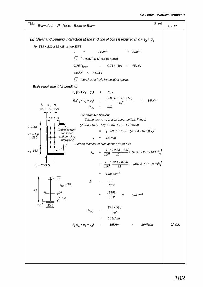
Example 1 – Fin Plates - Beam to BeamSheetTitle
Fin Plates - Worked Example 1
183
9 of 12
(ii) Shear and bending interaction at the 2nd line of bolts is required if c > e3 + gb
For 533 x 210 x 92 UB grade S275
c = 110mm > 90mm
∴ Interaction check required
0.75 Pv.min = 0.75 x 603 = 452kN
350kN < 452kN
∴ low shear criteria for bending applies
Basic requirement for bending:
Fv (t1 + e3 + gb) ≤ McC
350 (10 + 40 + 50)Fv (t1 + e3 + gb) = –––––––––––––––––– = 35kNm
103
McC = py Z
For Gross tee Section: Taking moments of area about bottom flange:
(209.3 x 15.6 x 7.8) + (467.4 x 10.1 x 249.3)
= [(209.3 x 15.6) + (467.4 x 10.1)] x y
y = 151mm
Second moment of area about neutral axis:
1 209.3 x 15.63Ixx = ––– [ ––––––––––– + (209.3 x 15.6 x 143.22)]
104 12
1 10.1 x 467.53+ ––– [ ––––––––––– + (467.4 x 10.1 x 98.32)]
104 12
= 19858cm4
Ixx Z = ––– ymax
19858 = –––––– = 598 cm3
33.2
275 x 598 McC = ––––––––––
103
= 164kNm
Fv (t1 + e3 + gb) = 35kNm < 164kNm ∴∴∴∴∴ O.K.
209.3
483
15.6
10.1
N A
y = 151
y = 332max
Critical section for shear
and bending interaction
= 350kN
(n – 1)p=280
e =163b
e = 40t
Fv
c = 110.
3 e
=40b
g
=50
t
=101
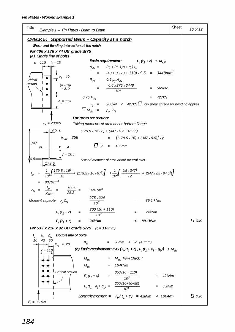
Example 1 – Fin Plates - Beam to BeamSheetTitle
Fin Plates - Worked Example 1
184
10 of 12
CHECK 5: Supported Beam – Capacity at a notch Shear and Bending interaction at the notch
For 406 x 178 x 74 UB grade S275 (a) Single line of bolts
Basic requirement: Fv (t1 + c) ≤ McN
AvN = (et + (n–1)p + eb) tw= (40 + 3 x 70 + 113) x 9.5 = 3448mm2
PvN = 0.6 py AvN
0.6 x 275 x 3448= ––––––––––––––––– = 569kN
103
0.75 PvN = 427kN
Fv = 200kN < 427kN∴ low shear criteria for bending applies
∴ McN = py ZN
For gross tee section:Taking moments of area about bottom flange:
(179.5 x 16 x 8) + (347 x 9.5 x 189.5)
= [(179.5 x 16) + (347 x 9.5)] x y
∴ ∴ ∴ ∴ ∴ y = 105mm
Second moment of area about neutral axis:
1 179.5 x 163 1 9.5 x 3473Ixx = ––– [ ––––––––––– + (179.5 x 16 x 972)] +––– [ ––––––––––– + (347 x 9.5 x 84.52)]
104 12 104 12
= 8370cm4
Ixx 8370ZN = –––– = ––––– = 324 cm3
ymax 25.8275 x 324
Moment capacity, py ZN = –––––––– = 89.1 kNm 103
200 (10 + 110)Fv (t1 + c) = –––––––––––––– = 24kNm
103
Fv (t1 + c) = 24kNm < 89.1kNm ∴∴∴∴∴ O.K.
For 533 x 210 x 92 UB grade S275 (c = 110mm)
Double line of bolts
xN = 20mm < 2d (40mm)
(b) Basic requirement: max (Fv (t1 + c) , Fv (t1 + e3 + gb)) ≤ McN
McN = McC from Check 4
McN = 164kNm
350 (10 + 110)Fv (t1 + c) = –––––––––––––– = 42kNm
103
350 (10+40+50)Fv (t1+ e3+ gb) = ––––––––––––––– = 35kNm
103
Eccentric moment = Fv ( t1 + c ) = 42kNm < 164kNm ∴∴∴∴∴ O.K.
Critical section
= 350kNFv
c = 110
x = 20N
3 e
=40b
g
=50
t
=101
= 200kN
t = 10 1
e = 113b
c = 110
(n – 1)p= 210
e = 40tCritical section
Fv
179.5
347
16y = 105
9.5
N A
y = 258max

Example 1 – Fin Plates - Beam to BeamSheetTitle
Fin Plates - Worked Example 1
185
11 of 12
CHECK 6: Supported Beam - Local Stablity of notched beamWhen the beam is restrained against lateral torsional buckling no accountneed be taken of notch stability provided that:
For one flange notched beam in S275 steel
Basic requirements:D
Notch depth dc1 ≤≤≤≤≤ ––2
Dand c ≤≤≤≤≤ D for –– ≤≤≤≤≤ 54.3
tw160000D D
c ≤≤≤≤≤ ––––––––– for –– > 54.3( D/tw )3 t w
For 406 x 178 x 74 UB Grade S275 (c = 110mm dc1 = 50mm tw = 9.5mm D = 412.8mm)
412.8Notch depth dc1 = 50mm < ––––– = 206.4mm ∴∴∴∴∴ O.K.
2
D 412.8–– = ––––– = 43.5 < 54.3 tw 9.5
c = 110mm < 412.8mm ∴∴∴∴∴ O.K.
For 533 x 210 x 92 UB (c =110 mm dc1 = 50mm tw = 10.1mm D = 533.1mm)
533.1Notch depth dc1 = 50mm < –––––– = 266.6mm ∴ ∴ ∴ ∴ ∴ O.K..
2
D 533.1–– = ––––– = 52.8 < 54.3 tw 10.1
c = 110mm < 533.1mm ∴∴∴∴∴ O.K.
CHECK 7: Not applicable (because the supported beam is being considered as restrained against lateral torsional buckling)

Example 1 – Fin Plates - Beam to BeamSheetTitle
Fin Plates - Worked Example 1
186
12 of 12
CHECK 8: Supporting Beam - Welds Basic requirement: s > 0. 8 tf
0. 8 tf = 0.8 x 10 = 8mm
∴∴∴∴∴ Use 8mm fillet welds
CHECK 9: Not applicable
CHECK 10: Supporting Beam - Local Capacity (two supported beams)
Fv1A Fv2(iii) Basic requirement: –––– + ––– ≤ Pv2 2
Fv1 l2 350 x 290Fv1A = –––– = –––––––– = 282kN
l1 360
Fv1B = 350 – 282 = 68kN
Web thickness of supporting member, tw = 13.1mm
Shear capacity,Pv = 0.6 Py A v
Shear area, Av = 0.9l2 tw = 0.9 x 290 x 13.1
= 3419mm2
0.6 x 275 x 3419 P v = 0.6py Av = –––––––––––––––
103
= 564kN
Fv1A Fv2 282 200––– + ––– = ––– + ––– = 241kN 2 2 2 2
Fv1A Fv2––– + ––– = 241kN < 564kN ∴∴∴∴∴ O.K. 2 2
F = 350kNF = 200kN
290360
Fv2 Fv1A
Fv1B
l =l =
12
v1v2

Example 2 - Fin Plates - Beam to UC column web – Structural Integrity SheetTitle
Fin Plates - Worked Example 2
187
BCSA
CALCULATIONSHEET
Calcs by
Title
Client
Checked by Date
Job No SheetJoints in Steel Construction - Simple Connections
Example 2 - Fin Plates - Beam to UC column web - Structural Integrity
SCI/BCSA Connections Group
RS AM May 2002
1 of 6
DESIGN EXAMPLE 2
Check the following beam to column connection for the tie force shown.
Design Information:
Bolts: M20 8. 8Material: All S275Fin Plate: 100 x 10 thk
Welds: 8mm Fillet Weld
50
40
70
70
70
40406 x 178 x 74 UB
Grade S275
50 50
175kNTie force
8
Column305 x 305 x 137 UC
Grade S275
See figure 6.5 andYellow pagesTable H.4

Example 2 - Fin Plates - Beam to UC column web – Structural Integrity SheetTitle
Fin Plates - Worked Example 2
188
CONNECTION DESIGN USING CAPACITY TABLES FROM YELLOW PAGES
Fin plate type FA4 Grade S275
Bolts M20 8.8
8mm fillet weld
From capacity table H.27 in yellow pages
Connection tying capacity = 350kN > 175kN ∴ ∴ ∴ ∴ ∴ O.K.
∴∴∴∴∴ Beam side of connection is adequate.
Note:
(1) The tying capacity of the connection given in the table in the yellow pages is thelesser of the values obtained from CHECKS 11 & 12.
(2) Beams connecting into a column web must also be checked for column web bendingas shown in CHECK 14 on sheet 6.
406 x 178 x 74 UBGrade S275
305 x 305 x 137 UCGrade S275
175kNTie force
2 of 6
Yellow pagesTable H.4
Yellow pagesTable H.27
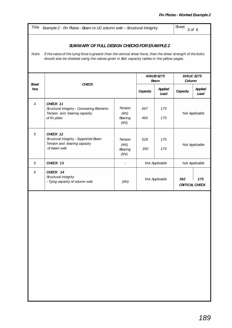
Example 2 - Fin Plates - Beam to UC column web – Structural Integrity SheetTitle
Fin Plates - Worked Example 2
189
3 of 6
SUMMARY OF FULL DESIGN CHECKS FOR EXAMPLE 2
Note: If the value of the tying force is greater than the vertical shear force, then the shear strength of the boltsshould also be checked using the values given in Bolt capacity tables in the yellow pages.
406UB S275 305UC S275Beam Column
Sheet CHECKNos
CapacityApplied
CapacityApplied
Load Load
4 CHECK 11Structural Integrity - Connecting Elements Tension 667 175Tension and bearing capacity (kN) Not Applicableof fin plate Bearing 460 175
(kN)
5 CHECK 12Structural integrity - Supported Beam Tension 528 175Tension and bearing capacity
(kN) Not Applicable of beam web Bearing 350 175
(kN)
5 CHECK 13 - Not Applicable Not Applicable
6 CHECK 14Structural integrity
Not Applicable 362 175- Tying capacity of column web (kN)
CRITICAL CHECK

Example 2 - Fin Plates - Beam to UC column web – Structural Integrity SheetTitle
Fin Plates - Worked Example 2
190
4 of 6
CHECK 11: Structural Integrity - Connecting Elements
(i) For tension:
Basic requirement: Tie force ≤ Tension capacity of fin plate
Tension capacity of fin plate = min ( py A , Ke py Anet )
A = l tf = 290 x 10 = 2900mm2
Anet = A – n Dh tf = 2900 – 4 x 22 x 10 = 2020mm2
275 x 2900py A = ––––––––– = 798kN
103
1.2 x 275 x 2020Ke py Anet = ––––––––––––– = 667kN
103
Tie Force = 175kN < 667kN ∴∴∴∴∴ O.K.
(ii) For bearing:
Basic requirement: Tie force ≤ Bearing capacity of fin plate
Bearing capacity of fin plate = 1.5n d tf pbs but ≤ 0.5n e2 tf pbs
1.5 x 4 x 20 x 10 x 4601.5n d tf pbs = ––––––––––––––––––– = 552kN
103
0.5 x 4 x 50 x 10 x 4600.5n e2 tf pbs = ––––––––––––––––––– = 460kN
103
∴ Bearing capacity of fin plate = 460kN
Tie Force = 175kN < 460kN ∴∴∴∴∴ O.K.
Pbs fromBS 5950–1Table 32
p = 70
e = 401
e = 401
Hole diameter D = 22mm
Fin plate thickness, t = l0mmh
fTie force = 175kN
l
50e = 502

Example 2 - Fin Plates - Beam to UC column web – Structural Integrity SheetTitle
Fin Plates - Worked Example 2
191
CHECK 12: Structural Integrity of supported beam
(i) For Tension:
Basic requirement: Tie force ≤ Net tension capacity of beam web
Net tension capacity of beam web = Le tw py
Effective net length, L e = 2ee + (n – 1) pe – n Dh
ee = e3 (but ≤ e = 40mm
p e = p (but ≤ 2e3) = 70mm
Dh = hole diameter = 22mm
Beam web thickness, tf = 9.5mm
∴ Le = (2 x 40) + [(4–1)70] – (4 x 22) = 202mm
202 x 9.5 x 275∴ Net tension capacity of beam web = ––––––––––––– = 528kN 103
Tie Force = 175kN < 528kN ∴∴∴∴∴ O.K.
(ii) For Bearing:
Basic requirement: Tie force ≤ Bearing capacity of beam web
Bearing capacity of beam web = 1.5n d tw pbs but ≤ 0.5n e3 tw pbs
tw = web thickness = 9.5mm
pbs = 460N/mm2
1.5 x 4 x 20 x 9.5 x 4601.5n d tw pbs = –––––––––––––––––––– = 524kN
103
0.5 x 4 x 40 x 9.5 x 4600.5n e3 tw pbs = –––––––––––––––––––– = 350kN
103
Bearing capacity of beam web = 350kN
Tie Force = 175kN < 350kN ∴∴∴∴∴ O.K.
CHECK 13: Not applicable (see Table 3.1)
5 of 6
e = 40
e = 90
p = 70
t
Tie force175kN
3
pbs fromBS 5950-1Table 32
t)

Example 2 - Fin Plates - Beam to UC column web – Structural Integrity SheetTitle
Fin Plates - Worked Example 2
192
CHECK 14: Structural Integrity - Supporting column web
Basic requirement: Tie force ≤ Tying capacity of column web
Tying capacity 8 Mu= ––––– ( η
1 + 1.5(1 – β1)0.5 )of column web 1 – β 1
Mu = moment capacity of column web per unit length
pu t w2
= –––––– 4
328 x 13.82= –––––––––– = 15.6kNm/mm
4 x 10³
l 290η1 = –– = ––––– = 1.176
dc 246.7
tf + 2s 10 + (2 x 8)β1 = ––––––– = ––––––––– = 0.105
dc 246.7
Tying capacity 8 x 15.6= ––––––––– (1.176 + 1.5(1 – 0.105)0.5 )of column web 1 – 0.105
= 139.4 (1.176 + 1.419) = 362kN
Tie Force = 175kN < 362kN ∴ ∴ ∴ ∴ ∴ O.K.
Note: If column web fails to satisfy the above criteria then stiffeners fillet welded on one sideto the web and flanges would be required thus:
6 of 6
l = 290305 x 305 x 137 UC
Grade S275
175kNTie Force
d = 246.7 c
2s + t = 26f
t = 13.8w

Example 3 - Fin Plates - Beam to RHS columnSheetTitle
Fin Plates - Worked Example 3
193
BCSA
CALCULATIONSHEET
Calcs by
Title
Client
Checked by Date
Job Sheet
Joints in Steel Construction - Simple Connections
Example 3 - Fin Plates - Beam to RHS column
SCI/BCSA Connections Group
RS May 2002
DESIGN EXAMPLE 3
Check the following beam to RHS column connection for the design forces shown.In this example it is assumed that the tying force is equal to the end reaction. However, dependingon how the floor beams are arranged, the tying force given by the formula in BS 5950-1 clause2.4.5.3 can sometimes be less.
Note: The connections should be checked independently for (i) shear forces and (ii) Tie forcesand NOT for both forces at the same time.
Design Information:
Bolts: M20 8.8Welds: 8mm fillet weld
Column: S355Beams: S275
Fin plates: S275
1 of 9
5050 50
40
70
70
70
70
40
10 Projection
200kN 350kN
406 x 178 x 74 UBGrade S275
200kNtie
force
40
70
70
70
250 x 250 x 12.5 RHS Grade S355
10 Projection
533 x 210 x 92 UBGrade S275
350kNtie
force
40
AW / AM
100 x 10Fin plate (Type FA4)
150 x 10Fin plate (Type FB5)
8 8
See figure 6.4 andYellow pagesTable H.4

Example 3 - Fin Plates - Beam to RHS columnSheetTitle
Fin Plates - Worked Example 3
194
2 of 9
CONNECTION DESIGN USING CAPACITY TABLES FROM YELLOW PAGES
Fin Plate type FA4 Grade S275 Fin Plate type FB5 Grade S275Bolts M20 8.8 Bolts M20 8.8
From capacity table H.27 in Yellow pages: From capacity table H.28 in Yellow pages:
Connection shear capacity Connection shear capacity= 265kN > 200kN 476kN > 350kN ∴∴∴∴∴ O.K.
Max notch length Max notch length(c + t1) = 336 > Zero (c + t1) = 345 > Zero ∴∴∴∴∴ O.K.
Minimum support thickness Minimum support thickness= 4.8mm < 12.5mm = 6.3mm < 12.5mm ∴∴∴∴∴ O.K.
Connection tying capacity Connection tying capacity= 350kN > 200kN 694kN > 350kN ∴∴∴∴∴ O.K.
Beam side of connection is adequate Beam side of connection is adequate
200kN 350kN
406 x 178 x 74 UBGrade S275
200kNtie
force
533 x 210 x 92 UBGrade S275
350kNtie
force
250 x 250 x 12.5 RHS Grade S355
Yellow pagesTables
H.27 and H.28
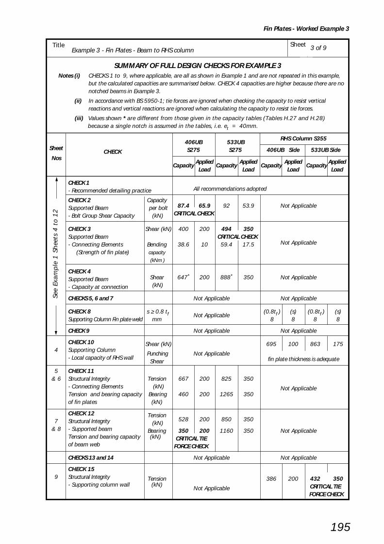
Example 3 - Fin Plates - Beam to RHS columnSheetTitle
Fin Plates - Worked Example 3
195
3 of 9
SUMMARY OF FULL DESIGN CHECKS FOR EXAMPLE 3Notes (i) CHECKS 1 to 9, where applicable, are all as shown in Example 1 and are not repeated in this example,
but the calculated capacities are summarised below. CHECK 4 capacities are higher because there are nonotched beams in Example 3.
(ii) In accordance with BS 5950-1; tie forces are ignored when checking the capacity to resist verticalreactions and vertical reactions are ignored when calculating the capacity to resist tie forces.
(iii) Values shown * are different from those given in the capacity tables (Tables H.27 and H.28) because a single notch is assumed in the tables, i.e. et = 40mm.
406UB 533UBRHS Column S355
Sheet CHECK S275 S275
406UB Side 533UB Side
NosCapacity
AppliedCapacity
AppliedCapacity
AppliedCapacity
AppliedLoad Load Load Load
CHECK 1- Recommended detailing practice All recommendations adopted
CHECK 2 Capacity87.4 65.9 92 53.9 Not ApplicableSupported Beam
per bolt
CRITICAL CHECK- Bolt Group Shear Capacity (kN)
CHECK 3 Shear (kN) 400 200 494 350Supported Beam CRITICAL CHECK- Connecting Elements Bending 38.6 10 59.4 17.5 Not Applicable
(Strength of fin plate) capacity
(kNm )
CHECK 4Supported Beam Shear 647* 200 888* 350 Not Applicable
- Capacity at connection (kN)
CHECKS 5, 6 and 7 Not Applicable Not Applicable
CHECK 8 s ≥ 0.8 tf Not Applicable (0.8tf ) (s) (0.8tf ) (s)
Supporting Column Fin plate weld mm 8 8 8 8
CHECK 9 Not Applicable Not Applicable
CHECK 10 Shear (kN) 695 100 863 1754 Supporting Column
Punching Not Applicable fin plate thickness is adequate- Local capacity of RHS wall
Shear
5 CHECK 11& 6 Structural Integrity Tension 667 200 825 350
- Connecting Elements (kN) Not ApplicableTension and bearing capacity Bearing 460 200 1265 350of fin plates (kN)
CHECK 12 Tension7 Structural Integrity (kN)
528 200 850 350
& 8 - Supported beam Bearing 350 200 1160 350 Not ApplicableTension and bearing capacity (kN) CRITICAL TIEof beam web FORCE CHECK
CHECKS 13 and 14 Not Applicable Not Applicable
CHECK 159 Structural Integrity Tension 386 200 432 350
- Supporting column wall (kN)Not Applicable CRITICAL TIE
FORCE CHECK
See
Exa
mpl
e 1
Sh
eets
4 t
o 1
2

Example 3 - Fin Plates - Beam to RHS columnSheetTitle
Fin Plates - Worked Example 3
196
CHECK 10: Supporting Column - Local capacity
Shear and punching shear capacity of column wall
(i) Local shear capacity Basic requirement: Fv / 2 ≤ Pv
For 406 x 178 x 74 UB sideFv /2 = 100kN
Shear capacity, Pv = 0.6 py Av
Av = 0.9 l tw
= 0.9 x 290 x 12.5 = 3263mm2
0.6 x 355 x 3263∴ Pv = –––––––––––––––– = 695kN 103
Fv /2 = 100kN < 695kN ∴∴∴∴∴ O.K.
For 533 x 210 x 92 UB side
Fv /2 = 175kN
Av = 0.9 x 360 x 12.5 =4050mm2
0.6 x 355 x 4050∴ Pv = –––––––––––––––– = 863kN 103
Fv /2 = 175kN < 863kN ∴∴∴∴∴ O.K.
(ii) Punching shear Basic requirement (using the conservative method for both beam sides):
Usctf ≤ tw x (––– ) pyf
Usc = 490N/mm2 and pyf = 275N/mm2
Usc 490tw x ––– = 12.5 x –––– = 22.3mm pyf
275
tf = 10mm < 22.3mm ∴ ∴ ∴ ∴ ∴ O.K.
4 of 9
Usc fromTable H.45
Yellow pages
250 x 250 x 12.5 RHS Column Grade S355
5050 50406 x 178 x 74 UBGrade S275
533 x 210 x 92 UBGrade S275
wt = 12.5 mmwall thickness
F = 350kNF = 200kN
l = 290
l = 360
v v
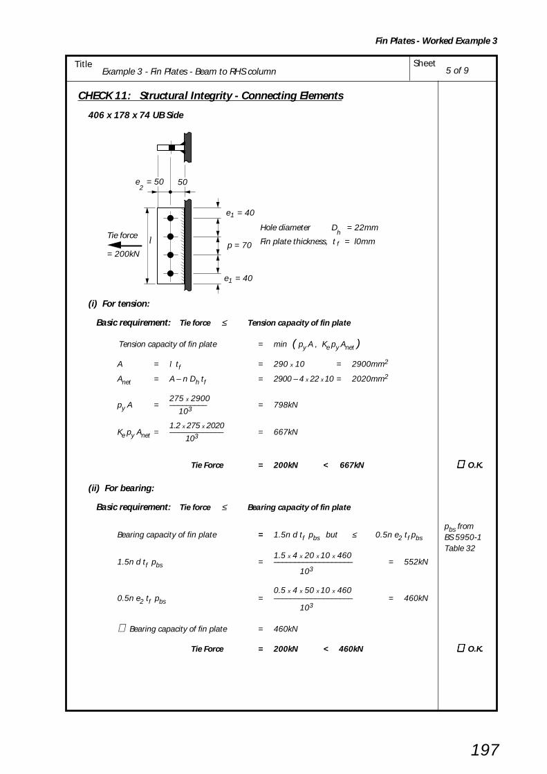
Example 3 - Fin Plates - Beam to RHS columnSheetTitle
Fin Plates - Worked Example 3
197
CHECK 11: Structural Integrity - Connecting Elements
406 x 178 x 74 UB Side
(i) For tension:
Basic requirement: Tie force ≤ Tension capacity of fin plate
Tension capacity of fin plate = min ( py A , Ke py Anet )
A = l tf = 290 x 10 = 2900mm2
Anet = A – n Dh tf = 2900 – 4 x 22 x 10 = 2020mm2
275 x 2900py A = ––––––––– = 798kN
103
1.2 x 275 x 2020Ke py Anet = ––––––––––––– = 667kN
103
Tie Force = 200kN < 667kN ∴∴∴∴∴ O.K.
(ii) For bearing:
Basic requirement: Tie force ≤ Bearing capacity of fin plate
Bearing capacity of fin plate = 1.5n d tf pbs but ≤ 0.5n e2 tf pbs
1.5 x 4 x 20 x 10 x 4601.5n d tf pbs = ––––––––––––––––––– = 552kN
103
0.5 x 4 x 50 x 10 x 4600.5n e2 tf pbs = ––––––––––––––––––– = 460kN
103
∴ Bearing capacity of fin plate = 460kN
Tie Force = 200kN < 460kN ∴∴∴∴∴ O.K.
pbs fromBS 5950-1Table 32
5 of 9
p = 70
e = 401
e = 401
Hole diameter D = 22mm
Fin plate thickness, t = l0mmh
fTie force = 200kN
l
50e = 502
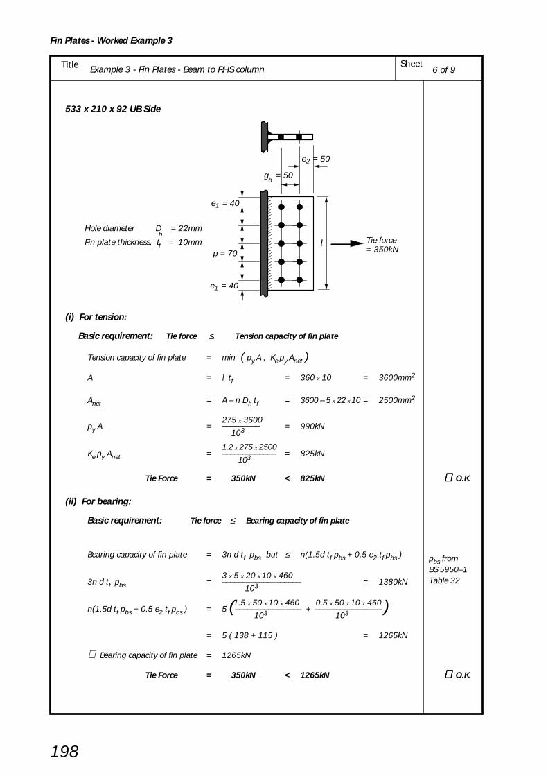
Example 3 - Fin Plates - Beam to RHS columnSheetTitle
Fin Plates - Worked Example 3
198
533 x 210 x 92 UB Side
(i) For tension:
Basic requirement: Tie force ≤ Tension capacity of fin plate
Tension capacity of fin plate = min ( py A , Ke py Anet )
A = l tf = 360 x 10 = 3600mm2
Anet = A – n Dh tf = 3600 – 5 x 22 x 10 = 2500mm2
275 x 3600py A = ––––––––– = 990kN
103
1.2 x 275 x 2500Ke py Anet = ––––––––––––– = 825kN
103
Tie Force = 350kN < 825kN ∴∴∴∴∴ O.K.
(ii) For bearing:
Basic requirement: Tie force ≤ Bearing capacity of fin plate
Bearing capacity of fin plate = 3n d tf pbs but ≤ n(1.5d tf pbs + 0.5 e2 tf pbs )
3 x 5 x 20 x 10 x 4603n d tf pbs = ––––––––––––––––––– = 1380kN
103
1.5 x 50 x 10 x 460 0.5 x 50 x 10 x 460n(1.5d tf pbs + 0.5 e2 tf pbs ) = 5 (–––––––––––––––– + –––––––––––––––– )
103 103
= 5 ( 138 + 115 ) = 1265kN
∴ Bearing capacity of fin plate = 1265kN
Tie Force = 350kN < 1265kN ∴∴∴∴∴ O.K.
pbs fromBS 5950–1Table 32
6 of 9
p = 70
e = 401
Hole diameter D = 22mm
Fin plate thickness, t = 10mmh
fTie force= 350kN
e = 401
g = 50b
e = 502
l
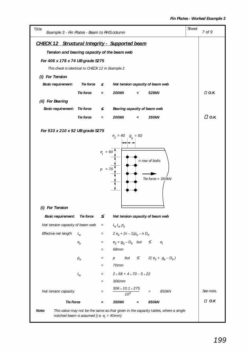
Example 3 - Fin Plates - Beam to RHS columnSheetTitle
Fin Plates - Worked Example 3
199
CHECK 12 Structural Integrity - Supported beam
Tension and bearing capacity of the beam web
For 406 x 178 x 74 UB grade S275
This check is identical to CHECK 12 in Example 2
(i) For Tension
Basic requirement: Tie force ≤≤≤≤≤ Net tension capacity of beam web
Tie force = 200kN < 528kN ∴∴∴∴∴ O.K.
(ii) For Bearing
Basic requirement: Tie force ≤≤≤≤≤ Bearing capacity of beam web
Tie force = 200kN < 350kN ∴∴∴∴∴ O.K.
For 533 x 210 x 92 UB grade S275
(i) For Tension
Basic requirement: Tie force ≤≤≤≤≤ Net tension capacity of beam web
Net tension capacity of beam web = Le tw py
Effective net length Le = 2 ee + (n – 1)pe – n Dh
ee = e3 + gb – Dh but ≤ et
= 68mm
pe = p but ≤ 2( e3 + gb – Dh )
= 70mm
Le = 2 x 68 + 4 x 70 – 5 x 22
= 306mm
306 x 10.1 x 275Net tension capacity = –––––––––––––– = 850kN
103
Tie Force = 350kN < 850kN
Note: This value may not be the same as that given in the capacity tables, where a singlenotched beam is assumed (i.e. et = 40mm)
See note.
∴∴∴∴∴ O.K
7 of 9
e = 90t
p = 70
n row of bolts
Tie force = 350kN
e = 403
g = 50b

Example 3 - Fin Plates - Beam to RHS columnSheetTitle
Fin Plates - Worked Example 3
200
(ii) For Bearing
Basic requirement: Tie Force ≤≤≤≤≤ Bearing capacity of beam web
Bearing capacity of the beam web = 3 n d tw pbs
but ≤ n ( 1.5 d tw pbs + 0.5 e3 tw pbs)
3 x 5 x 20 x 10.1x 4603 n d tw pbs = –––––––––––––––––– = 1394kN
103
1.5 x 20 x 10.1 x 460 0.5 x 40 x 10.1 x 460n ( 1.5 d tw pbs + 0.5 e3 tw pbs) = 5 ( –––––––––––––––– + ––––––––––––––––)
103 103
= 5 (139 + 93) = 1160kN
Bearing capacity of beam web = 1160kN
∴∴∴∴∴ Tie force = 350kN < 1160kN ∴∴∴∴∴ O.K.
CHECK 13: Not applicable see Table 3.1
CHECK 14: Not applicable see Table 3.1
8 of 9

Example 3 - Fin Plates - Beam to RHS columnSheetTitle
Fin Plates - Worked Example 3
201
9 of 9
CHECK 15: Structural lntegrity – Capacity of Supporting Column Wall (RHS)
Basic requirement: Tie force ≤ Tying capacity of RHS column wall
Tying capacity 8 Mu= ––––– ( η
+ 1.5(1 – β)0.5 )of column web 1 – β
Mu = moment capacity of RHS column wall per unit length
pu t w2
392 x 12.52= –––––– = –––––––––– = 15.3kNm/mm
4 4 x 10³
tf + 2s 10 + (2 x 8)β = ––––––– = –––––––––– = 0.122
B – 3tw 250 – (3 x 12.5)
lη = ––––B – 3tw
For 406 x 178 x 74 UB side
290η = –––––––––– = 1.364250 – (3 x 12.5)
Tying capacity 8 x 15.3= ––––––––– (1.364 + 1.5(1 – 0.122)0.5)of column wall 1 – 0.122
= 139.41 (1.364+ 1.406) = 386kN
Tie force = 200N < 386kN ∴∴∴∴∴ O.K.
For 533 x 210 x 92 UB side
360η = –––––––––– = 1.694250 – (3 x 12.5)
Tying capacity 8 x 15.3= ––––––––– ( 1.694 + 1.5(1 – 0.122)0.5)of column wall 1 – 0.122
= 139.41 (1.694 + 1.406) = 432kN
Tie force = 350kN < 432kN ∴∴∴∴∴ O.K.
l = 290 for 406 x 178 x 74 UB
350kNTie Force
B = 250
t = 12.5 w
2s + t = 26f
200kNTie Force
l = 360 for 533 x 210 x 92 UB
250 x 250 x 12.5 RHSGrade S355
pu fromproceduresCHECK 15

Example 4 - Fin Plates - Beam to CHS column SheetTitle
Fin Plates - Worked Example 4
202
BCSA
CALCULATIONSHEET
Calcs by
Title
Client
Checked by Date
Job Sheet
Joints in Steel Construction - Simple Connections
Example 4 - Fin Plates - Beam to CHS column
SCI/BCSA Connections Group
RS AW / AM May 2002
DESIGN EXAMPLE 4
Check the following beam to CHS column connection for the design forces shown.In this example it is assumed that the tying force is equal to the end reaction. However, dependingon how the floor beams are arranged, the tying force given by the formula in BS 5950-1 clause2.4.5.3 can sometimes be less.
Note: The connections should be checked independently for (i) Shear forces and (ii) Tie forces and NOT for both forces acting at the same time.
Design Information:Bolts: M20 8.8
Welds: 8mm Fillet weldColumn: S355Beams: S275
Fin Plates: S275
1 of 6
5050 50
40
70
70
70
7040
10 Projection
200kN 350kN
406 x 178 x 74 UBGrade S275
200kNtie
force
40
70
70
70
244.5 x 12.5 CHS Grade S355
10 Projection
533 x 210 x 92 UBGrade S275
350kNtie
force
40
100 x 10Fin plate (Type FA4)
150 x 10Fin plate (Type FB5)
8 8 See figure 6.4 andYellow pagesTable H.4
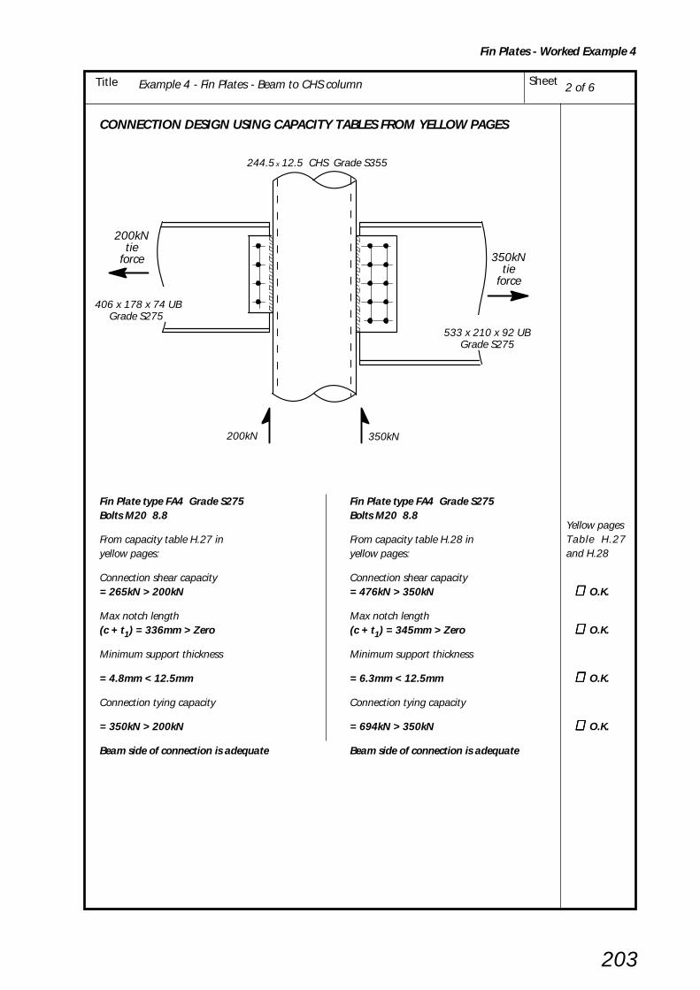
Example 4 - Fin Plates - Beam to CHS column SheetTitle
Fin Plates - Worked Example 4
203
CONNECTION DESIGN USING CAPACITY TABLES FROM YELLOW PAGES
Fin Plate type FA4 Grade S275 Fin Plate type FA4 Grade S275Bolts M20 8.8 Bolts M20 8.8
From capacity table H.27 in From capacity table H.28 inyellow pages: yellow pages:
Connection shear capacity Connection shear capacity= 265kN > 200kN = 476kN > 350kN ∴∴∴∴∴ O.K.
Max notch length Max notch length(c + t1) = 336mm > Zero (c + t1) = 345mm > Zero ∴∴∴∴∴ O.K.
Minimum support thickness Minimum support thickness
= 4.8mm < 12.5mm = 6.3mm < 12.5mm ∴∴∴∴∴ O.K.
Connection tying capacity Connection tying capacity
= 350kN > 200kN = 694kN > 350kN ∴∴∴∴∴ O.K.
Beam side of connection is adequate Beam side of connection is adequate
200kN 350kN
406 x 178 x 74 UBGrade S275
200kNtie
force
244.5 x 12.5 CHS Grade S355
533 x 210 x 92 UBGrade S275
350kNtie
force
2 of 6
Yellow pagesTable H.27and H.28
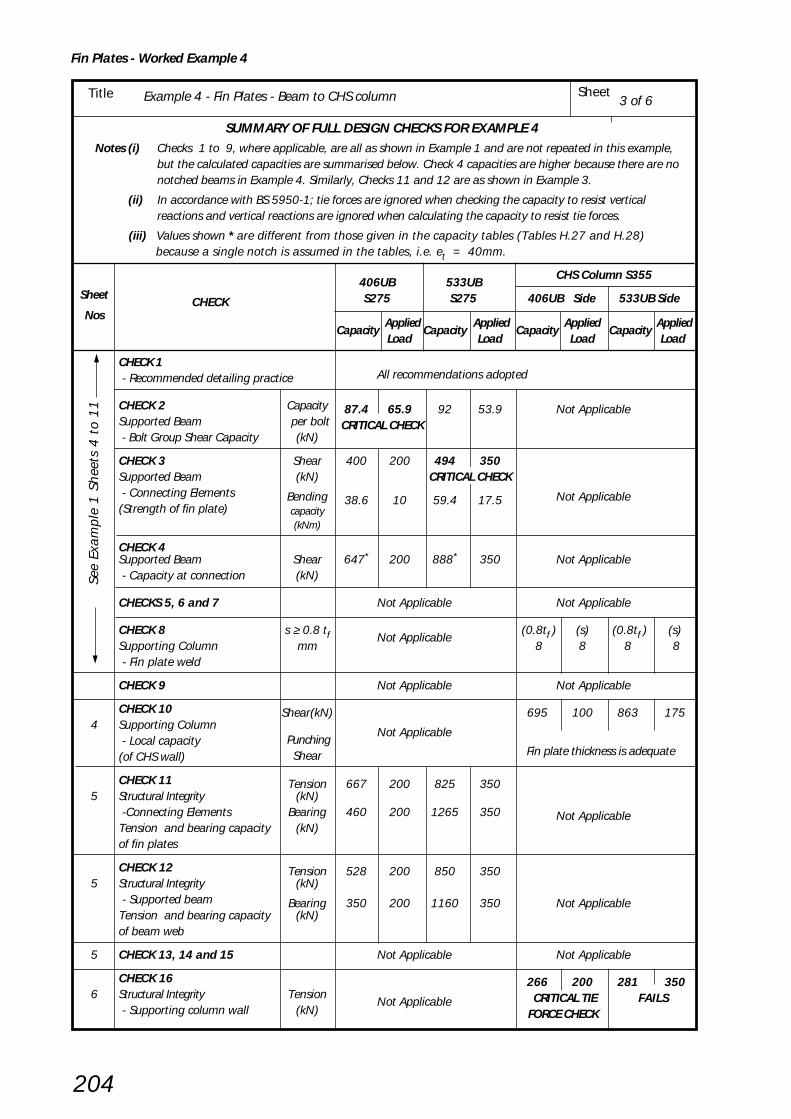
Example 4 - Fin Plates - Beam to CHS column SheetTitle
Fin Plates - Worked Example 4
204
3 of 6
SUMMARY OF FULL DESIGN CHECKS FOR EXAMPLE 4Notes (i) Checks 1 to 9, where applicable, are all as shown in Example 1 and are not repeated in this example,
but the calculated capacities are summarised below. Check 4 capacities are higher because there are nonotched beams in Example 4. Similarly, Checks 11 and 12 are as shown in Example 3.
(ii) In accordance with BS 5950-1; tie forces are ignored when checking the capacity to resist verticalreactions and vertical reactions are ignored when calculating the capacity to resist tie forces.
(iii) Values shown * are different from those given in the capacity tables (Tables H.27 and H.28) because a single notch is assumed in the tables, i.e. et = 40mm.
406UB 533UBCHS Column S355
Sheet CHECK S275 S275
406UB Side 533UB Side
Nos Capacity
AppliedCapacity
AppliedCapacity
AppliedCapacity
AppliedLoad Load Load Load
CHECK 1 - Recommended detailing practice All recommendations adopted
CHECK 2 Capacity 87.4 65.9 92 53.9 Not ApplicableSupported Beam
per bolt CRITICAL CHECK
- Bolt Group Shear Capacity (kN)
CHECK 3 Shear 400 200 494 350Supported Beam (kN) CRITICAL CHECK - Connecting Elements Bending 38.6 10 59.4 17.5 Not Applicable(Strength of fin plate) capacity
CHECK 4
(kNm)
Supported Beam Shear 647* 200 888* 350 Not Applicable - Capacity at connection (kN)
CHECKS 5, 6 and 7 Not Applicable Not Applicable
CHECK 8 s ≥ 0.8 tf Not Applicable (0.8tf ) (s) (0.8tf ) (s)
Supporting Column mm 8 8 8 8 - Fin plate weld
CHECK 9 Not Applicable Not Applicable
CHECK 10 Shear(kN) 695 100 863 1754 Supporting Column
PunchingNot Applicable
Fin plate thickness is adequate - Local capacity
Shear(of CHS wall)
CHECK 11 Tension 667 200 825 3505 Structural Integrity (kN)
-Connecting Elements Bearing 460 200 1265 350 Not ApplicableTension and bearing capacity (kN)of fin plates
CHECK 12 Tension 528 200 850 3505 Structural Integrity (kN)
- Supported beam Bearing 350 200 1160 350 Not ApplicableTension and bearing capacity (kN)of beam web
5 CHECK 13, 14 and 15 Not Applicable Not Applicable
CHECK 16 266 200 281 3506 Structural Integrity Tension
Not Applicable CRITICAL TIE FAILS
- Supporting column wall (kN) FORCE CHECK
See
Exa
mpl
e 1
Sh
eets
4 t
o 1
1
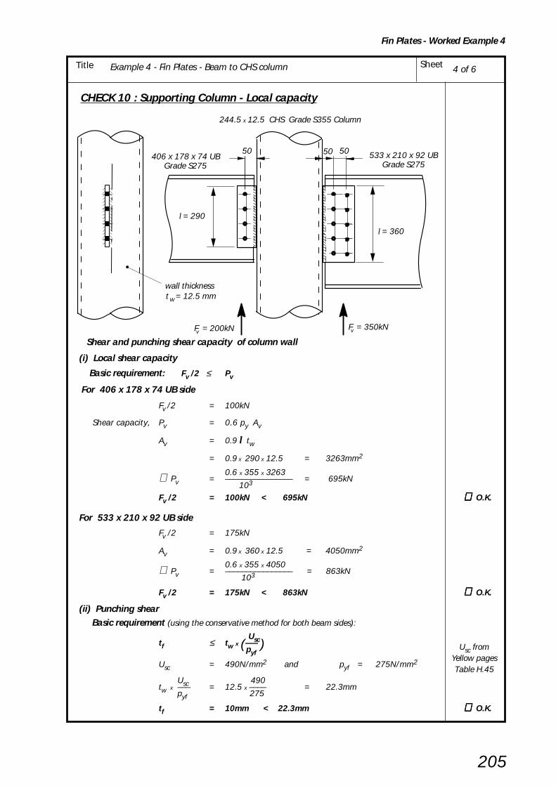
Example 4 - Fin Plates - Beam to CHS column SheetTitle
Fin Plates - Worked Example 4
205
CHECK 10 : Supporting Column - Local capacity
Shear and punching shear capacity of column wall
(i) Local shear capacity
Basic requirement: Fv /2 ≤ Pv
For 406 x 178 x 74 UB side
Fv /2 = 100kN
Shear capacity, Pv = 0.6 py Av
Av = 0.9 l tw
= 0.9 x 290 x 12.5 = 3263mm2
0.6 x 355 x 3263∴ Pv = –––––––––––––––– = 695kN 103
Fv /2 = 100kN < 695kN ∴ ∴ ∴ ∴ ∴ O.K.
For 533 x 210 x 92 UB side
Fv /2 = 175kN
Av = 0.9 x 360 x 12.5 = 4050mm2
0.6 x 355 x 4050∴ Pv = –––––––––––––––– = 863kN 103
Fv /2 = 175kN < 863kN ∴ ∴ ∴ ∴ ∴ O.K.
(ii) Punching shear Basic requirement (using the conservative method for both beam sides):
Usctf ≤ tw x (––– ) pyf
Usc = 490N/mm2 and pyf = 275N/mm2
Usc 490tw x ––– = 12.5 x –––– = 22.3mm pyf
275
tf = 10mm < 22.3mm ∴ ∴ ∴ ∴ ∴ O.K.
4 of 6
5050 50406 x 178 x 74 UB
Grade S275533 x 210 x 92 UB
Grade S275
wt = 12.5 mmwall thickness
F = 350kNF = 200kN
244.5 x 12.5 CHS Grade S355 Column
v v
l = 290
l = 360
Usc fromYellow pagesTable H.45

Example 4 - Fin Plates - Beam to CHS column SheetTitle
Fin Plates - Worked Example 4
206
CHECK 11 Structural Integrity - Connecting Elements (This check is identical to CHECK 11 in Example 3.)
406 x 178 x 74 UB side
(i) For Tension
Basic requirement: Tie force ≤ Tension capacity of fin plate
200kN ≤≤≤≤≤ 667kN ∴∴∴∴∴ O.K.
(ii) For Bearing
Basic requirement: Tie force ≤ Bearing capacity of fin plate
200kN ≤ 460kN ∴∴∴∴∴ O.K.
533 x 210 x 92 UB Grade S275
(i) For Tension
Basic requirement: Tie force ≤ Tension capacity of fin plate
350kN ≤ 825kN ∴∴∴∴∴ O.K.
(ii) For Bearing
Basic requirement: Tie force ≤ Bearing capacity of fin plate
350kN ≤ 1265kN ∴∴∴∴∴ O.K.
CHECK 12 Structural Integrity - Supported beam (This check is identical to CHECK 12 in Example 3.)
406 x 178 x 74 UB Grade S275
(i) For Tension
Basic requirement: Tie force ≤ Net tension capacity of beam web
200kN ≤ 528kN ∴∴∴∴∴ O.K.
(ii) For Bearing
Basic requirement: Tie force ≤ Bearing capacity of beam web
200kN ≤ 350kN ∴∴∴∴∴ O.K.
533 x 210 x 92 UB Grade S275
(i) For Tension
Basic requirement: Tie force ≤ Net tension capacity of beam web
350kN ≤ 850kN ∴∴∴∴∴ O.K.
(ii) For Bearing
Basic requirement: Tie force ≤ Bearing capacity of beam web
350kN ≤ 1160kN ∴∴∴∴∴ O.K.
CHECK 13 Not applicable See Table 3.1
CHECK 14 Not applicable See Table 3.1
CHECK 15 Not applicable See Table 3.1
5 of 6
Example 3Fin Plates
Sheet 5 of 9
Example 3Fin Plates
Sheet 5 of 9
Example 3Fin Plates
Sheet 6 of 9
Example 3Fin Plates
Sheet 6 of 9
Example 3Fin Plates
Sheet 7 of 9
Example 3Fin Plates
Sheet 7 of 9
Example 3Fin Plates
Sheet 7 of 9
Example 3Fin Plates
Sheet 8 of 9

Example 4 - Fin Plates - Beam to CHS column SheetTitle
Fin Plates - Worked Example 4
207
6 of 6
CHECK 16: Structural lntegrity – Capacity of Supporting Column Wall (CHS)
Basic requirement: Tie force ≤ Tying capacity of CHS column wall
Tying capacity= 5 pu tw
2 (1 + 0.25 η) x 0.67of CHS column wall
pu = design tensile strength of column wall
Us= ––––––= 392 N/mm2
1.25
lη = –––– but ≤ 4 D
For 406 x 178 x 74 UB side
290η = ––––––– = 1.186 244.5
Tying capacity 5 x 392 x 12.52 ( 1 + (0.25 x 1.186)) x 0.67= ––––––––––––––––––––––––––––––––––––––of column wall 103
= 266kN
Tie force = 200kN < 266kN ∴∴∴∴∴ O.K.
For 533 x 210 x 92 UB side
360η = ––––––– = 1.472 244.5
Tying capacity 5 x 392 x 12.52 ( 1 + (0.25 x 1.472)) x 0.67= ––––––––––––––––––––––––––––––––––––––of column wall 103
= 281kN
Tie force = 350kN <| 281kN ∴∴∴∴∴ FAILS
Use a deeper fin plate for 533 UB Side.
l = 290 for 406 x 178 x 74 UB
350kNTie Force
D = 244.5200kN
Tie Force
l = 360 for 533 x 210 x 92 UB
t = 12.5 w
244.5 x 12.5 CHS Grade S355
pu fromproceduresCHECK 16

208
7. COLUMN SPLICES
7.1 INTRODUCTION
Column splices in multi-storey construction are usuallyprovided every two or three storeys and are located justabove floor level. This results in convenient lengths forfabrication, transport and erection, and gives easy accessfrom the adjacent floor for bolting up on site. Theprovision of splices at each storey level is seldomeconomical since the saving in column material isgenerally far outweighed by the material, fabricationand erection costs of making the splice.
Typical bolted column splices used for rolled I -sectionand hollow section members are shown in Figure 7.1.
Bolted cover plate splices for I -sections:There are two categories for this type of connection:
• Bearing type (see Figure 7.3). Here the loads aretransferred in direct bearing from the upper shafteither directly or through a division plate.
The 'bearing type' is the simpler connection, usuallyhaving far fewer bolts than the non-bearing splice,and is therefore the one most commonly used inpractice.
• Non-bearing type (see Figure 7.4). In this caseloads are transferred via the bolts and splice plates.Any bearing between the members is ignored, the
connection sometimes being detailed with a physicalgap between the two shafts.
For more heavily loaded splices the end result can beexpensive, involving a large amount of fabrication andsite bolting
Splices are generally provided just above floor levels(typically 500mm above) hence moment due to strutaction is considered insignificant. The moments inducedin splices placed at other positions should be checked.
Column splices should hold the connected members inline and wherever practical the members should bearranged so that the centroidal axis of the splice materialcoincides with the centroidal axis of the column sectionsabove and below the splice.
Bolted 'cap and base' or 'end plate' splicesfor tubular and rolled I -sectionsThis type of splice, consisting of 'cap and base' or endplates which are welded to the ends of the lower andupper columns and then simply bolted together on site, iscommonly used in tubular construction but has alsogained in popularity in recent years for rolled I -section.
The most simple form of the connection is as shown infigure 7.2 and is satisfactory as long as the ends of eachshaft are prepared in the same way as for a bearing typesplice and also due attention is paid to other considerationssuch as load reversal making the splice a tension connection,stability during erection and structural integrity. This typeof connection can then be both simple and cost effective.
In a splice connection with end plates it is generally moredifficult to achieve the same stiffness as the member thanit is for the cover plate splices. An accurate elastic analysisof the connection should be used to verify that it is at leastas stiff as the member. It is likely that relatively thick endplates will be needed. Extended end plates may berequired if there is a significant moment. Even where asplice connecion is entirely in compression, it is advisableto maintain full continuity of stiffness through theconnection to safeguard the robustness of the structure.
Figure 7.2 'Cap and base' or 'End plate' splice
'Base plate'
'Cap plate'
Figure 7.1 Splice connections
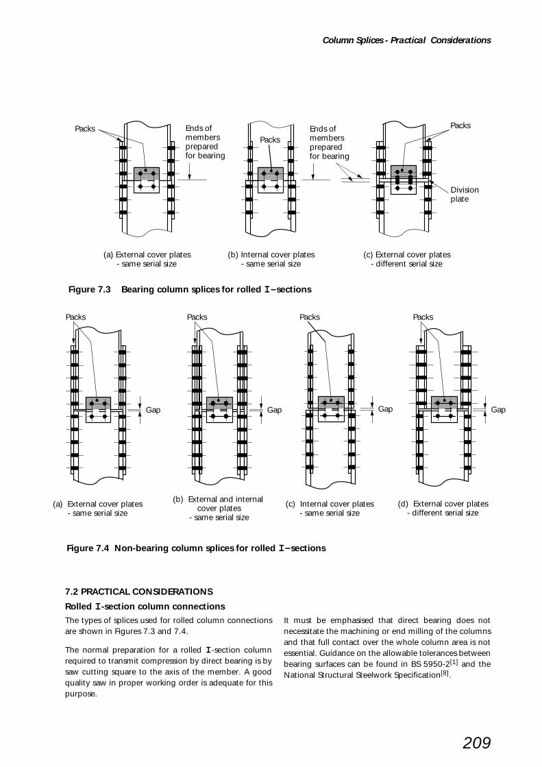
209
Figure 7.4 Non-bearing column splices for rolled I - sections
Figure 7.3 Bearing column splices for rolled I - sections
Column Splices - Practical Considerations
Packs Ends ofmembers preparedfor bearing
Ends ofmembers preparedfor bearing
Divisionplate
(a) External cover plates- same serial size
(b) Internal cover plates- same serial size
(c) External cover plates- different serial size
Packs
Packs
7.2 PRACTICAL CONSIDERATIONS
Rolled I -section column connectionsThe types of splices used for rolled column connectionsare shown in Figures 7.3 and 7.4.
The normal preparation for a rolled I -section columnrequired to transmit compression by direct bearing is bysaw cutting square to the axis of the member. A goodquality saw in proper working order is adequate for thispurpose.
It must be emphasised that direct bearing does notnecessitate the machining or end milling of the columnsand that full contact over the whole column area is notessential. Guidance on the allowable tolerances betweenbearing surfaces can be found in BS 5950-2[1] and theNational Structural Steelwork Specification[8].
(a) External cover plates- same serial size
Gap
(b) External and internal cover plates
- same serial size
Gap
(d) External cover plates- different serial size
Gap
(c) Internal cover plates- same serial size
Gap
Packs PacksPacks Packs
210
CHS and RHS tubular connections'Cap and base' or 'end plate' splice connections aresuitable for tubular members in both compression andtension. For simple designs the recommendations includedhere are those in the Cidect Guides[28][29].
Implicit in the design procedures is an allowance forprying forces; the 'exact method bolt tension capacity'can therefore be used.
Preferred splice typesPractical considerations lead to bearing type splices beingrecommended in most cases. However if constructionaldifficulties are encountered (e.g. the need to splice toexisting steelwork) then a non-bearing splice may be theonly alternative. In such cases a physical gap should bedetailed between the columns, and the splice componentsshould be designed accordingly.
In non-bearing splices joining members of different serialsize, multiple packs are necessary to take up thedimensional variations. In order to limit the packing toreasonable proportions no more than one jump in thecolumn serial size should be taken at each splice. Furtherrules on the packing follow in the design checks. Theserestrictions on packing do not apply when high strengthfriction grip bolts are used.
For architectural reasons, it will often be necessary to keepthe width of the connection to a minimum. If this is thecase, then either countersunk bolts, or narrow flangeplates bolted to the inside of the flanges can be used asshown in Figure 7.3(b) and 7.4(c). By using both theseoptions, it is possible to detail a splice that is no wider thanthe column section itself.
FastenersGenerally the capacities and design strengths of fastenersand fittings should be based on the rules given in BS 5950-1, clause 6.3. The fastener spacing and edge distancesshould comply with the requirements of clause 6.2 of thatcode.
For the majority of cases 8.8, M20 or M24, bolts will beadequate for cover plate splices; the flange bolts areinserted with the heads on the outside. Countersunk boltsmay be used if flush surfaces are required, modifying thechecks as appropriate.
Untorqued bolts in clearance holes are normally used,except in cases where significant net tension may bepresent or where slip is unacceptable. Situations wherejoint slip may be unacceptable include splices in a bracedbay subjected to large load reversals. In cases wheresignificant net tension may be present, either general grade
HSFG bolts can be used, or alternatively the connectioncould be detailed with 'cap and base' plates as shown inFigure 7.2. As a guide, net tension is considered significantwhen it exceeds 10% of the design strength (py) of theupper column.
HolesHoles in fittings may be punched full size, using semi-automatic equipment, within the limits laid down InBS 5950-2[1] and in accordance the National StructuralSteelwork Specification[8]. Holes through thicker fittingsand column flange and web are usually drilled.
Splice fittingsSplice fittings are usually fabricated using S275 materialand standard flats. Appropriate sizes may not be availablefor the heavier splices and in such cases the fittings will becut from plate.
If a division plate is necessary, it will either be nominallywelded to the column or bolted to the web using anglecleats. The latter option gives the opportunity for the plateto be easily removed on site if any adjustments arenecessary.
Division plates will normally be sized approximately5mm smaller than the lower column size to permit easyfitting, and will normally be flat enough for tight bearingwithout the need for machining or flattening.
Packing shims are usually detailed 5mm short of thebearing surfaces to avoid the possibility of slip and cuttingtolerances resulting in the ends being trapped.
7.3 RECOMMENDED GEOMETRY
The main aims when detailing column splices are asfollows:
• to provide a connection that is capable of carryingthe design loads:
• to ensure that members are held accurately in positionrelative to each other;
• to provide a degree of continuity of stiffness about bothaxes:
• to provide sufficient rigidity to hold the upper shaftsafely in position during erection[30].
Detailing requirements for splices outlined in this Sectionare based mainly on past experience, and these guidelineshave been used to produce the standard bearing splicesfor rolled sections included in the yellow pages.
Column Splices - Recommended Geometry

211
7.4 DESIGN
The design check procedures for column coverplate splicesin rolled sections are described in detail for bearing splicesin Section 7.5 and for non-bearing splices in Section 7.6.
The design check procedures for RHS and CHS bolted 'capand base' splices, when subject to tensile forces, aredescribed in Sections 7.7 and 7.8 respectively.
Bearing splicesThe procedures require bearing splices to be initiallychecked to establish whether the design forces andmoments induce net tension in any part of the connection.If net tension does occur then further checks must becarried out on the flange cover plates and bolts. With nonet tension a standard connection such as shown in theyellow pages can be used without further checks.
It is not necessary to achieve an absolutely perfect fit overthe entire bearing surface. Normally, ends of columns thatare sawn cut are adequately smooth and flat for bearingwithout machining. The actual bearing of the ends of eachcolumn is dependent upon the accuracy of erection; aftererection the ends bed down as successive dead loads areapplied to the structure.
It can be assumed that full contact in bearing has beenachieved, provided that the gap between the bearingsurfaces, after erection, complies with clause 9.5.5 ofthe National Structural Steelwork Specification.[8]
Non-bearing splicesThe design of a non-bearing splice is more involved, as allforces and moments must be transmitted through thebolts and splice plates. The connection must be checkedboth for compression and for any net tension that mayoccur.
Shear forceThe horizontal shear force arising from the momentgradient is normally resisted by friction across the contactbearing surfaces and/or by the web cover plates. Windforces on the external elevations of buildings are normallytaken directly into the floor slabs. If instead they are takeninto the steel columns it is usual to position the connectionsbetween the wall and the column such that the splice isnot subject to wind shear. It is rare for column splices insimple construction be expected to transmit wind shears,and thus no design methods are presented in this guide.
Structural integrityThe Building Regulations require that certain tall multi-storey buildings must be designed so that accidentaldamage does not lead to disproportionate collapse. Clause2.4.5 of BS 5950-1[1] lays down a set of rules for steelframes that are deemed to satisfy these requirements.
In such cases, the flange cover plates and associated boltgroups should be checked for a total tensile force equal tothe largest factored vertical dead and imposed load reactionapplied to the column at a single floor level locatedbetween that column splice and the next column splicedown.
Worked examplesFive worked examples are provided in Section 7.9; threeexamples illustrate the design checks for rolled sectioncover plate splices and two design checks for hollowsection splices in full tension.
Column splice tablesA fully detailed set of bearing-type coverplate splices forcommon combinations of UC columns is included in theyellow pages (Tables H.32 and H.33). Rationalised boltspacing and fittings sizes have been adopted and thesemay be used for most splices. Tension capacities are givenfor bolted cover plates on each flange and these values canbe used either for the net tension or for the structuralintegrity checks.
For the use of preloaded HSFG bolts see Table H.31 note 6.
Non-bearing splices are infrequently used for rolledcolumns so tables are not provided for this type ofconnection. However, Tables H.36, H.37 and H.38 areprovided for bolted splices in CHS and RHS members intension.
Column Splices - Design

212
Recommended design model
When the splice is being made between columns of thesame serial size, the transfer of axial forces from the uppershaft to the lower shaft can be in direct bearing becausethe inner profile of the lighter section will always align withthe inner profile of the heavier section. The flange coverplates can be arranged to connect either to the externalfaces of the column (when pairs of packing plates will berequired with a thickness equating to the difference in thedepth dimension of the two sizes) or alternatively to theinner flanges by using split cover plates.
When the splice is being made between columns whichare of different serial sizes, the transfer of axial forces fromthe upper shaft to the lower shaft is made through a
where
M = nominal moment due to factored dead and imposed loads (ie. columndesign moment) at the floor level immediately below the splice.
Fcd = axial compressive force due to factored dead load only.
Fv = shear force.
D = conservatively, the overall depth of the smaller column (for externalflange cover plates) or the centreline to centreline distance betweenthe flange cover plates (for internal flange cover plates).
CHECK 1 Recommended detailing practice
CHECK 2 Flange cover plates – Determine whether net tension is present
CHECK 3 Flange cover plates – Tensile capacity of cover plates
CHECK 4 Flange cover plates – Bolt group
CHECK 5 Structural integrity – Cover plates and bolt group
M
Fcd
Fv
MD
+Fcd
2( )
Fv
MD
–Fcd
2( )
M
Fcd
Fv
MD
+Fcd
2( )
Fv
MD
–Fcd
2( )
horizontal division plate provided between the shafts toensure an adequate load path. Flange cover plates thenconnect to the external faces of the column shafts.
In normal circumstances the horizontal shear force arisingfrom the moment gradient is resisted by friction across thecontact bearing surfaces and/or by the web cover plate,but no specific checks are presented here. See furtheradvice in Section 7.4.
Design procedures are summarised below. CHECK 1gives the size parameters for the splice, CHECKS 2 to 4are strength checks required when tension is presentand CHECK 5 is required for structural integrity design.
7.5 DESIGN PROCEDURE
COVER PLATE SPLICES FOR I - COLUMNS - BEARING TYPE
Column Splices (Bearing Type) - Rolled steel I sections - Design Procedures

Column Splices (Bearing Type) - Rolled steel I sections - Design Procedures
213
CHECK 1Recommended detailing practice
Columns (UC or UB) – Bearing spliceExternal flange cover plates
Butting surfaces of sections in direct bearing
Direct bearing onto a division plate
cleat length ≥ 0.5D1
Web cover plate width ≥ 0.5D1
≥45°
Flange cover plate
Projection Lfp ≥ B1 and 225mm
Width Wfp≥ B1Thickness ≥ T1/2 and 10mm
Multiple packsThickness tpa
Web cover plateat least 4 no.M20, 8.8 boltsSee notes (1)&(2)
Lfp
Lfp
D2 Wfp
Wide bolt spacingfor joint rigidity
Packs arranged as necessary
Bolts (normally untorqued in clearance holes)See notes (1)&(2)
B11D
gb
B2
T1
t2
t1
Multiple packsthickness tpa
Web angle cleatsat least 2 no. M20, 8.8 bolts each side
Lfp
Lfp
Division plate thicknessdetermined by the stiff bearing provisions of clause 4.5.1.3 of BS 5950-1
Flange cover plateas above
T1
Notes:
(1) Bolt spacing and edge distances should comply with the recommendations of BS 5950-1:2000.
(2) If there is significant net tension (see CHECK 3) then the notes from CHECK 1 for Non-bearing splicesshould be adhered to.

214
Column Splices (Bearing Type) - Rolled steel I sections - Design Procedures
Recommended detailing practiceColumns (UC or UB) – Bearing splice
Internal flange cover plates
CHECK 1(continued)
Internal flange cover plates
Web cover plate width ≥ 0.5D1
Flange cover plate
Projection Lfp ≥ B1 and 225mm
Width Wfp≥ (B1 – t2 – 2r2)/2 (r2 = root radius)
Thickness ≥ T1/2 and 10mm
Web cover plateat least 4 no.M20, 8.8 bolts
T
Lfp
Lfp
D2
D1
Wide bolt spacingfor joint rigidity
Packs arranged as necessary
Bolts (normally untorqued in clearance holes)
B1
B2
t1
gb
t2
WfpWfp
1
Notes:
(1) Bolt spacing and edge distances should comply with the recommendations of BS 5950-1:2000.
(2) If there is significant net tension (see CHECK 3) then the notes from CHECK 1 for Non-bearing splicesshould be adhered to.
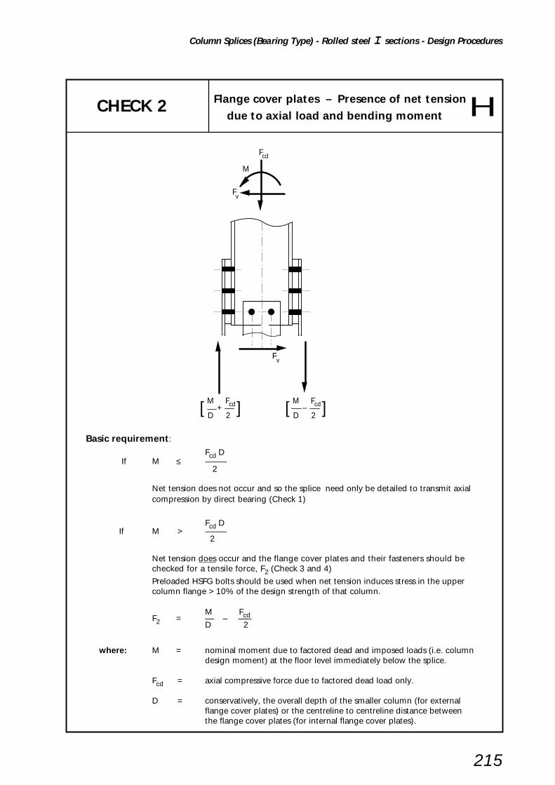
Column Splices (Bearing Type) - Rolled steel I sections - Design Procedures
215
CHECK 2
Basic requirement:
Fcd D If M ≤ –––––
2
Net tension does not occur and so the splice need only be detailed to transmit axialcompression by direct bearing (Check 1)
Fcd DIf M > –––––
2
Net tension does occur and the flange cover plates and their fasteners should bechecked for a tensile force, F2 (Check 3 and 4)
Preloaded HSFG bolts should be used when net tension induces stress in the uppercolumn flange > 10% of the design strength of that column.
M FcdF2 = –– – –––D 2
where: M = nominal moment due to factored dead and imposed loads (i.e. columndesign moment) at the floor level immediately below the splice.
Fcd = axial compressive force due to factored dead load only.
D = conservatively, the overall depth of the smaller column (for externalflange cover plates) or the centreline to centreline distance betweenthe flange cover plates (for internal flange cover plates).
M
Fcd
Fv
Fv
[ M
D ]Fcd
2+ [ M
D ]Fcd
2–
Flange cover plates – Presence of net tension
due to axial load and bending moment

216
Column Splices (Bearing Type) - Rolled steel I sections - Design Procedures
CHECK 3 Flange cover plateTensile capacity of cover plate
Flange cover plate
TensionF2
F2
Columnflange
critical section
Basic requirement:
F2 ≤ min (py Afp , KepyAfp.net )
whereF2 is as given by CHECK 2
Afp = gross area of flange cover plate(s) attached to one flange
Afp.net= net area of flange cover plate(s) attached to one flange
Ke = 1.2 for S275 steel ,{ See BS 5950-1= 1.1 for S355 steel clause 3.4.3 }
Check for significant net tension:
F2If –––––––– > 0.1 then preloaded HSFG bolts should be usedT1 B1 py1
where:
T1 = Upper column flange thickness
B1 = Upper column flange width
py1 = Upper column design strength
Note:
(1 It is sufficiently accurate to base this calculation on the gross area of the flange.
(2) When the tension is due to structural integrity requirements it is not necessary to use preloaded HSFG bolts.
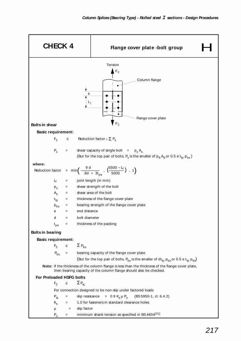
Column Splices (Bearing Type) - Rolled steel I sections - Design Procedures
217
CHECK 4 Flange cover plate -bolt group
Bolts in shear
Basic requirement:
F2 ≤ Reduction factor x Σ Ps
Ps = shear capacity of single bolt = ps As
(But for the top pair of bolts, Ps is the smaller of ps As or 0.5 e tfp pbs )
where: 9 d 5500 – Lj
Reduction factor = min( –––––––––– , (–––––––– ) , 1) 8d + 3tpa 5000
Lj = joint length (in mm)
ps = shear strength of the bolt
As = shear area of the bolt
tfp = thickness of the flange cover plate
pbs = bearing strength of the flange cover plate
e = end distance
d = bolt diameter
tpa = thickness of the packing
Bolts in bearing
Basic requirement:
F2 ≤ Σ Pbs
Pbs = bearing capacity of the flange cover plate
(But for the top pair of bolts, Pbs is the smaller of dtfp pbs or 0.5 e tfp pbs)
Note: If the thickness of the column flange is less than the thickness of the flange cover plate,then bearing capacity of the column flange should also be checked.
For Preloaded HSFG boltsF2 ≤ Σ PsL
For connection designed to be non-slip under factored loads
PsL = slip resistance = 0.9 Ks µ Po (BS 5950-1, cl. 6.4.2)
Ks = 1.0 for fasteners in standard clearance holes
µ = slip factor
Po = minimum shank tension as specified in BS 4604[31]
e
L j
Tension
F 2
F 2
Column flange
Flange cover plate
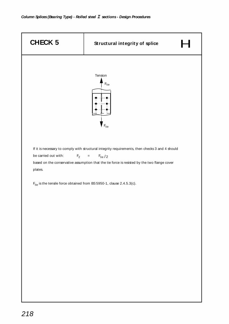
218
Column Splices (Bearing Type) - Rolled steel I sections - Design Procedures
CHECK 5 Structural integrity of splice
If it is necessary to comply with structural integrity requirements, then checks 3 and 4 should
be carried out with: F2 = Ftie /2
based on the conservative assumption that the tie force is resisted by the two flange cover
plates.
Ftie is the tensile force obtained from BS 5950-1, clause 2.4.5.3(c).
Ftie
Ftie
Tension
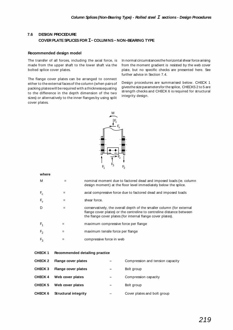
Column Splices (Non-Bearing Type) - Rolled steel I sections - Design Procedures
219
Recommended design model
The transfer of all forces, including the axial force, ismade from the upper shaft to the lower shaft via thebolted splice cover plates.
The flange cover plates can be arranged to connecteither to the external faces of the column (when pairs ofpacking plates will be required with a thickness equatingto the difference in the depth dimension of the twosizes) or alternatively to the inner flanges by using splitcover plates.
In normal circumstances the horizontal shear force arisingfrom the moment gradient is resisted by the web coverplate, but no specific checks are presented here. Seefurther advice in Section 7.4.
Design procedures are summarised below. CHECK 1gives the size parameters for the splice, CHECKS 2 to 5 arestrength checks and CHECK 6 is required for structuralintegrity design.
7.6 DESIGN PROCEDURE
COVER PLATE SPLICES FOR I - COLUMNS - NON-BEARING TYPE
where
M = nominal moment due to factored dead and imposed loads (ie. columndesign moment) at the floor level immediately below the splice.
Fc = axial compressive force due to factored dead and imposed loads
Fv = shear force.
D = conservatively, the overall depth of the smaller column (for externalflange cover plates) or the centreline to centreline distance betweenthe flange cover plates (for internal flange cover plates).
F1 = maximum compressive force per flange
F2 = maximum tensile force per flange
F3 = compressive force in web
CHECK 1 Recommended detailing practice
CHECK 2 Flange cover plates – Compression and tension capacity
CHECK 3 Flange cover plates – Bolt group
CHECK 4 Web cover plates – Compression capacity
CHECK 5 Web cover plates – Bolt group
CHECK 6 Structural integrity – Cover plates and bolt group
M
Fc
Fv
F1
Fv
F3 F2
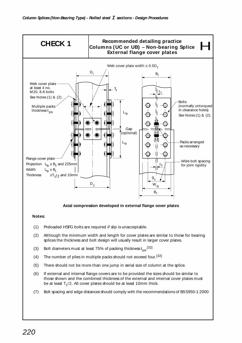
220
Column Splices (Non-Bearing Type) - Rolled steel I sections - Design Procedures
Multiple packsthickness tpa
Web cover plateat least 4 no.M20, 8.8 boltsSee Notes (1) & (2).
L fp
L fp
D2
Gap(optional)
1D
W fp
Wide bolt spacingfor joint rigidity
Packs arranged as necessary
B1
gb
B2
t1
t2
Bolts (normally untorqued in clearance holes)See Notes (1) & (2).
T1
Recommended detailing practiceColumns (UC or UB) – Non-bearing Splice
External flange cover plates
CHECK 1
Axial compression developed in external flange cover plates
Notes:
(1) Preloaded HSFG bolts are required if slip is unacceptable.
(2) Although the minimum width and length for cover plates are similar to those for bearingsplices the thickness and bolt design will usually result in larger cover plates.
(3) Bolt diameters must at least 75% of packing thickness tpa.[32]
(4) The number of plies in multiple packs should not exceed four.[32]
(5) There should not be more than one jump in serial size of column at the splice.
(6) If external and internal flange covers are to be provided the sizes should be similar tothose shown and the combined thickness of the external and internal cover plates mustbe at least T1/2. All cover plates should be at least 10mm thick.
(7) Bolt spacing and edge distances should comply with the recommendations of BS 5950-1:2000
Web cover plate width ≥ 0.5D1
Flange cover plate
Projection Lfp ≥ B1 and 225mm
Width Lfp ≥ B1Thickness ≥T1/2 and 10mm

Column Splices (Non-Bearing Type) - Rolled steel I sections - Design Procedures
221
Web cover plateat least 4 no.M20, 8.8 boltsSee Note (1) opposite
T
L fp
L fp
D2
W fp
t
D1
W fp
Gap(optional)
gb
2B
B1
Wide bolt spacingfor joint rigidity
Packs arranged as necessary
Bolts - normally untorqued in clearance holesSee Note (1) opposite.
t2
1 1
Recommended detailing practiceColumns (UC or UB) – Non-bearing splice
Internal flange cover plates
CHECK 1(continued)
Axial compression developed in internal flange cover plates
Web cover plate width ≥ 0.5D1
Flange cover plate
Projection Lfp ≥ B1 and 225mm
Width Wfp ≥ (B1 – t 2 – 2r2)/2
Thickness ≥T1/2 and 10mm
Notes:
The notes (1) and (3) to (7) opposite apply.
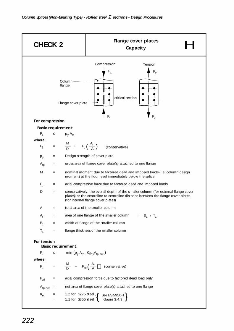
222
Column Splices (Non-Bearing Type) - Rolled steel I sections - Design Procedures
CHECK 2Flange cover plates
Capacity
For compression
Basic requirement:
F1 ≤ py Afp
where: M AfF1 = ––– + Fc ( ––– ) (conservative) D A
py = Design strength of cover plate
Afp = gross area of flange cover plate(s) attached to one flange
M = nominal moment due to factored dead and imposed loads (i.e. column designmoment) at the floor level immediately below the splice
Fc = axial compressive force due to factored dead and imposed loads
D = conservatively, the overall depth of the smaller column (for external flange coverplates) or the centreline to centreline distance between the flange cover plates(for internal flange cover plates)
A = total area of the smaller column
Af = area of one flange of the smaller column = B1 x T1
B1 = width of flange of the smaller column
T1 = flange thickness of the smaller column
For tension Basic requirement:
F2 ≤ min (py Afp , KepyAfp.net )
where: M AfF2 = ––– – Fcd( ––– ) (conservative) D A
Fcd = axial compression force due to factored dead load only
Afp.net = net area of flange cover plate(s) attached to one flange
Ke = 1.2 for S275 steel ,{ See BS 5950-1= 1.1 for S355 steel clause 3.4.3 }
F1
F1
Columnflange
critical section
F2
Compression
F2
Tension
Flange cover plate

Column Splices (Non-Bearing Type) - Rolled steel I sections - Design Procedures
223
CHECK 3Flange cover plates
Bolt Group
Bolts in shear
Basic requirement:
Max.(F1,F2) ≤ Reduction factor x Σ Ps
Ps = shear capacity of single bolt = ps As
(But for the top pair of bolts, Ps is the smaller of ps As and 0.5 e tfp pbs )
where: 9 d 5500 – Lj Reduction factor = min( –––––––––– , (–––––––––) , 1) 8d + 3tpa 5000
Lj = joint length (in mm)
ps = shear strength of the bolt
As = shear area of the bolt
tfp = thickness of the flange cover plate
pbs = bearing strength of the flange cover plate
e = end distance
d = bolt diameter
tpa = thickness of the packing
Bolts in bearing
Basic requirement:
Max.(F1,F2) ≤ Σ Pbs
Pbs = bearing capacity of the flange cover plate
(But for the top pair of bolts, Pbs is the smaller of dtfp pbs and 0.5 e tfp pbs)
Note: If the thickness of the column flange is less than the thickness of the flange cover plate,then bearing capacity of the column flange should also be checked.
For Preloaded HSFG bolts Max.(F1,F2) ≤ Σ PsL
For connection designed to be non-slip under factored loads
PsL = slip resistance = 0.9 Ks µ Po (BS 5950-1, cl. 6.4.2)
Ks = 1.0 for fasteners in standard clearance holes
µ = slip factor
Po = minimum shank tension as specified in BS 4604[31]
F1
F1
Columnflange
F2
Compression
F2
Tension
Flange cover plate
e
L j

224
Column Splices (Non-Bearing Type) - Rolled steel I sections - Design Procedures
Web cover plates
Capacity CHECK 4
Capacity of web cover plates
Basic requirement:
F3–– ≤ py Awp
2
Fc Awconservatively F3 = ––––– A
where: Fc = axial compressive force due to factored dead and imposed loads
A = total area of the smaller column
Aw = area of web of the smaller column = (A – 2Af)
Af = area of one flange of the smaller column
py = Design strength of web cover plates
Awp = gross area of one web cover plate
F 3
F3
F3
Web cover plates
Column
F3
2
F3
2

Column Splices (Non-Bearing Type) - Rolled steel I sections - Design Procedures
225
CHECK 5Web cover plates
Bolt group
Bolts in shear
Basic requirement:
F3–– ≤ Σ Ps2
where: F3 = As per Check 4
Ps = shear capacity of single bolt = ps As
(But for the top pair of bolts, Ps is the smaller of ps As or 0.5 e twp pbs)
ps = shear strength of the bolt
As = shear area of the bolt
twp = thickness of the web cover plate
pbs = bearing strength of the web cover plate
e = end distance
Bolts in bearing
F3 ≤ Σ Pbs
where Σ Pbs = bearing capacity of the web cover plate
Pbs = bearing capacity of the web cover plate per bolt = d t pbs
(But for the top pair of bolts, Pbs is the smaller of d t pbs or 0.5 e twp pbs)
d = bolt diameter
Note: If the thickness of the column web is less than the combined thickness of the web cover plates, then the bearing capacity of the column web should also be checked.
Web cover plates
Column
e
F3
2
F3
2F3
F3 F3
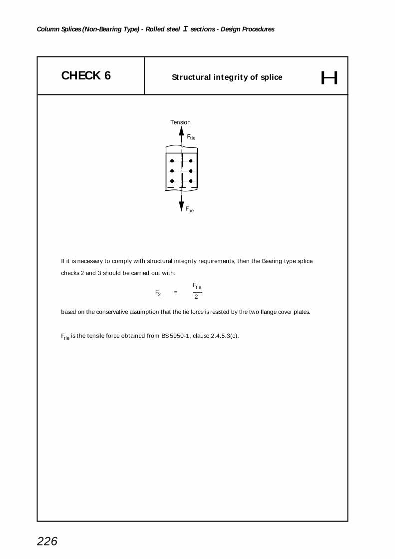
226
Column Splices (Non-Bearing Type) - Rolled steel I sections - Design Procedures
CHECK 6 Structural integrity of splice
If it is necessary to comply with structural integrity requirements, then the Bearing type splice
checks 2 and 3 should be carried out with:
FtieF2 = –––
2
based on the conservative assumption that the tie force is resisted by the two flange cover plates.
Ftie is the tensile force obtained from BS 5950-1, clause 2.4.5.3(c).
Ftie
Ftie
Tension

Tension Splices - RHS sections - Design Procedures
227
CHECK 1 – Recommended detailing practice
CHECK 2 – Complete end plate yielding (not applicable)
CHECK 3 – Bolt failure with end plate yielding
CHECK 4 – Bolt failure
CHECK 5 – Weld capacity
CHECK 6 – Member capacity
Recommended design model
The design procedures for tension splices in square andrectangular hollow sections considers tension bolts beingplaced along two parallel faces as shown below. Thereare no structural integrity checks given since the principalforce is tension.
Ft
Ft Ft
Ft
The semi-empirical rules are based on the recommendationsgiven in the CIDECT Design Guide[29] and take accountof prying forces; it is therefore permissible to use theexact method bolt tension capacities of BS 5950-1.
7.7 DESIGN PROCEDURERHS 'CAP AND BASE' OR 'END PLATE' SPLICE IN TENSION

228
Tension Splices - RHS sections - Design Procedures
CHECK 1Recommended detailing practice
RHS splice in tensionBolted end plates
plate thickness, tp12mm ≤ tp ≤ 26mm
See Note (2)
Hole diameter DhDh = d + 2mm for d ≤ 24mm
Dh = d + 3mm for d > 24mm
Bolt spacing p
p ≥ 2.5 d
t p
p
p
p
e 3
t p
e 1 e 2B e 1 e 2B
D
Edge distance e2 ≥ 1.4Dh
Edge distance e3 ≥ 1.4Dh
2DTotal number of bolts N ≤ –––– + 2 but ≥ 4
p
Notes:
(1) Dimension e1 to be kept to a minimum.
(2) Plate thickness tp should be limited to between 12mm and 26mm because thisis the range for which the design method has been validated experimentally.
CHECK 2 Complete end plate yielding(Not applicable due to plate thickness limitations)

Tension Splices - RHS sections - Design Procedures
229
CHECK 3 Bolt failure with end plate yielding
t p
t we 1
p p p
e 2
Ft Ft
Basic requirement:
tp2 ( 1 + δ α ) N
Ft ≤ ––––––––––––––– (kN) K
Dhδ = 1 – ––– p
4 (e1 – (d/2) + tw )103K = ––––––––––––––––
pyplate p
K Pt eeff + (d/2) α = ––––– – 1 ––––––––––––– but ≥ 0
tp2 δ ( eeff + e1 +tw)
where:tp = end plate thickness (mm)
N = total number of bolts (both rows)
Dh = bolt hole diameter (mm)
p = bolt pitch (mm)
d = bolt diameter (mm)
tw = RHS wall thickness (mm)
pyplate = design strength of plate (N/mm2)
Pt = Exact tension bolt capacity (kN)(see inset box)
eeff = minimum of e2 and 1.25e1 (mm)
Tension capacity - 8.8 bolts
Bolt sizeExact tension capacity
Pt
M20 137 kN
M24 198 kN
M30 314 kN

230
Tension Splices - RHS sections - Design Procedures
CHECK 4 Bolt failure
Basic requirement:
Ft ≤ N Pt (kN)
where:
Pt = Exact tension bolt capacity (kN)(see inset box)
N = total number of bolts (both rows)
Tension capacity - 8.8 bolts
Bolt sizeExact tension capacity
Pt
M20 137 kN
M24 198 kN
M30 314 kN
Ft Ft

Tension Splices - RHS sections - Design Procedures
231
Weld CHECK 5
Notes: (1) The weld should be capable of developing the full strength of the RHS. A fillet weld shouldnormally be used, but if the required leg length exceeds 12mm then a partial penetration buttweld with additional fillets may be a more economical solution.
(2) For a partial penetration butt weld with additional fillets, as shown in Figureabove, note that:
• the depth of preparation should be 3mm deeper than the required penetration.
• the minimum penetration of 2√t specified in BS 5950-1 clause 6.9.2 does not apply tothe detail shown.
(3) Depending on splice plate stiffness, the welded perimeter of RHS Sections will be loaded non-uniformly. In the absence of more precise design guidance, the effective weld length should betaken as the side lengths adjacent to the loaded bolts in tension.
Weld tensile capacity
Basic requirement:
Provide continuous full-strength weld (See Note (1)and (2)) or alternatively:
Ft ≤ 2D a (1.25pw)
where:D = RHS depth
pw = design strength of weldsee BS 5950-1 Table 37.(220N/mm2 for S275 steel250N/mm2 for S355 steel.)
For fillet weld:
a = weld throat thickness
= 0.7 s
s = weld leg length ≤ 12mm
For partial penetration butt with additional fillet:
a = weld throat thickness accordingto geometry shown in Figure above
3mm
fusi
on fa
ce 1
throat
fusion face 2
RHS wall
a
End plate
t w
s
D
B
continuous weld
Ft Ft

232
Tension Splices - RHS sections - Design Procedures
CHECK 6 Member capacity
F Ft t
Member capacity
Basic requirement:
Ft ≤ Apy
where:A = cross-sectional area of RHS
py = design strength of RHS

Tension Splices - CHS sections - Design Procedures
233
CHECK 1 – Recommended detailing practice
CHECK 2 – Complete end plate yeilding
CHECK 3 – Bolt failure with end plate yielding
CHECK 4 – Bolt failure
CHECK 5 – Weld capacity
CHECK 6 – Member capacity
7.8 DESIGN PROCEDURECHS END-PLATE SPLICE IN TENSION
Recommended design model
The design procedures for tension splices in circularhollow sections consider tension bolts being evenlyplaced radially around the section. There are no structuralintegrity checks given, since the principal force is tension.
The semi-empirical rules are based on the recommendationsgiven in the CIDECT Design Guide[28] and take accountof prying forces; it is therefore permissible to use theexact method bolt tension capacities.
Ft
Ft

234
Tension Splices - CHS sections - Design Procedures
CHECK 1Recommended detailing practice
CHS Splice in tensionBolted end plates
Notes: (1) Bolts to be equally spaced around circumference.
(2) At least 4 bolts to be used.
(2) Dimension e1 to be kept to a minimum.
Hole diameter DhDh = d + 2mm for d ≤ 24mm
Dh = d + 3mm for d > 24mm
Bolt spacing p
p ≥ 2.5 d
p ≤ 10 d
edge distance e2 ≥ 1.4 Dh
t pt p
e 2e 1
p
Ft
Ft
D

Tension Splices - CHS sections - Design Procedures
235
CHECK 2 Complete end plate yielding
Basic requirement:
tp2 pyplate π f3Ft ≤ ––––––––––––––
2
where: 1
f3 = –– ( k3 + (k32 – 4 k1)
0.5 )2k1
k1 = ln (r2 /r3) [ ln = natural logarithm ]
Dr2 = –– + e1 2
D – twr3 = ––––– 2
k3 = k1 + 2
tp = end plate thickness
pyplate = design strength of plate
D = CHS diameter
tw = CHS wall thickness
t w
t p
e 1
D
FtFt2r
r3
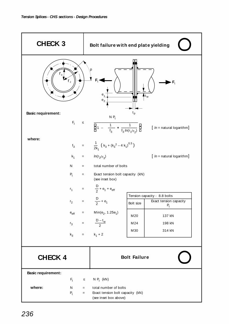
236
Tension Splices - CHS sections - Design Procedures
CHECK 3 Bolt failure with end plate yielding
Basic requirement: N Pt
Ft ≤ –––––––––––––––––––––––––––– 1 1 1 – –––– + ––––––––– [ ln = natural logarithm] f3 f3 ln(r1/r2)
where: 1
f3 = –– ( k3 + (k32 – 4 k1)
0.5 )2k1
k1 = ln(r2/r3) [ ln = natural logarithm]
N = total number of bolts
Pt = Exact tension bolt capacity (kN)(see inset box)
Dr1 = –– + e1 + eeff 2
Dr2 = ––– + e1 2
eeff = Min(e2, 1.25e1)
D – twr3 = –––––– 2
k3 = k1 + 2
Tension capacity - 8.8 bolts
Bolt sizeExact tension capacity
Pt
M20 137 kN
M24 198 kN
M30 314 kN
p
2r
r3
e 1
Ft
t w
t p
e 2
t p
Ft
CHECK 4 Bolt Failure
Basic requirement:
Ft ≤ N Pt (kN)
where: N = total number of boltsPt = Exact tension bolt capacity (kN)
(see inset box above)

Tension Splices - CHS sections - Design Procedures
237
Weld CHECK 5
Weld tensile capacity
Basic requirement: provide continuous full-strength weld (See Note (1)and (2)) or alternatively
Ft ≤ π D a pw
where:D = CHS diameter
pw = design strength of weldsee BS 5950-1 Table 37.(220N/mm2 for S275 steel250N/mm2 for S355 steel.)
For fillet weld:
a = weld throat thickness
= 0.7 s
s = weld leg length ≤ 12mm
For partial penetration butt with additional fillet:
a = weld throat thickness accordingto geometry shown in Figure above
D
continuous weld
t ws
Ft Ft
3mm
fusi
on fa
ce 1
throat
fusion face 2
CHS wall
a
End plate
t w
Notes: (1) The weld should be capable of developing the full strength of the CHS. A fillet weld shouldnormally be used, but if the required leg length exceeds 12mm then a partial penetration buttweld with additional fillets may be a more economical solution.
(2) For a partial penetration butt weld with additional fillets, as shown in Figureabove, note that:
• the depth of preparation should be 3mm deeper than the required penetration.
• the minimum penetration of 2√t specified in BS 5950-1 clause 6.9.2 does not apply tothe detail shown.

238
Tension Splices - CHS sections - Design Procedures
CHECK 6 Member capacity
Member capacity
Basic requirement:
Ft ≤ A py
where:A = cross-sectional area of CHS
py = design strength of CHS
Ft Ft

239
Column Splices - Worked examples
7.9 WORKED EXAMPLES
The five worked examples for splices illustrate the designchecks required for the most commonly used details:
Example 1: A bearing splice for connecting twodifferent size Universal Column sectionsusing external cover plates and with adivision plate between.
Example 2: A connection as Example 1 but with abending moment where net tension ispresent (additional checks which have tobe made are shown).
Example 3: A non-bearing splice for UCs with all forcesdeveloped in the bolted cover plates,including a structural integrity check.
Example 4: An RHS splice made with bolted end-plateswhich is subject to axial tension.
Example 5: A CHS splice made with bolted end-plateswhich is subject to axial tension.
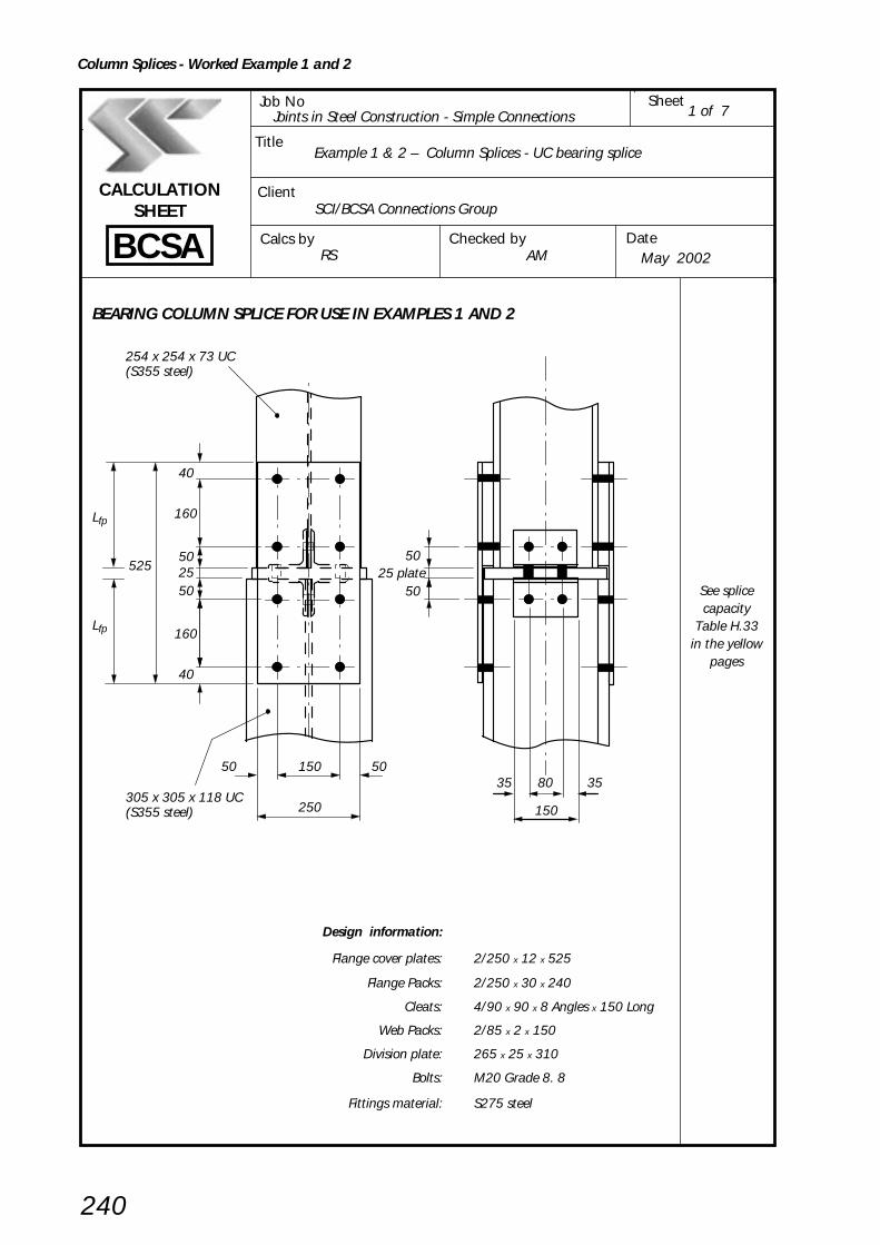
Example 1 – Column Splices – UC bearing splice (No net tension) SheetTitle
240
BCSA
CALCULATIONSHEET
Calcs by
Title
Client
Checked by Date
Job No SheetJoints in Steel Construction - Simple Connections
Example 1 & 2 – Column Splices - UC bearing splice
SCI/BCSA Connections Group
RS AM May 2002
1 of 7
BEARING COLUMN SPLICE FOR USE IN EXAMPLES 1 AND 2
Design information:
Flange cover plates: 2/250 x 12 x 525
Flange Packs: 2/250 x 30 x 240
Cleats: 4/90 x 90 x 8 Angles x 150 Long
Web Packs: 2/85 x 2 x 150
Division plate: 265 x 25 x 310
Bolts: M20 Grade 8. 8
Fittings material: S275 steel
See splicecapacity
Table H.33in the yellow
pages
40
40
160
160
50
5025525
Lfp
Lfp
250
15050 50
254 x 254 x 73 UC(S355 steel)
305 x 305 x 118 UC(S355 steel)
5025 plate
50
35 3580
150
Column Splices - Worked Example 1 and 2
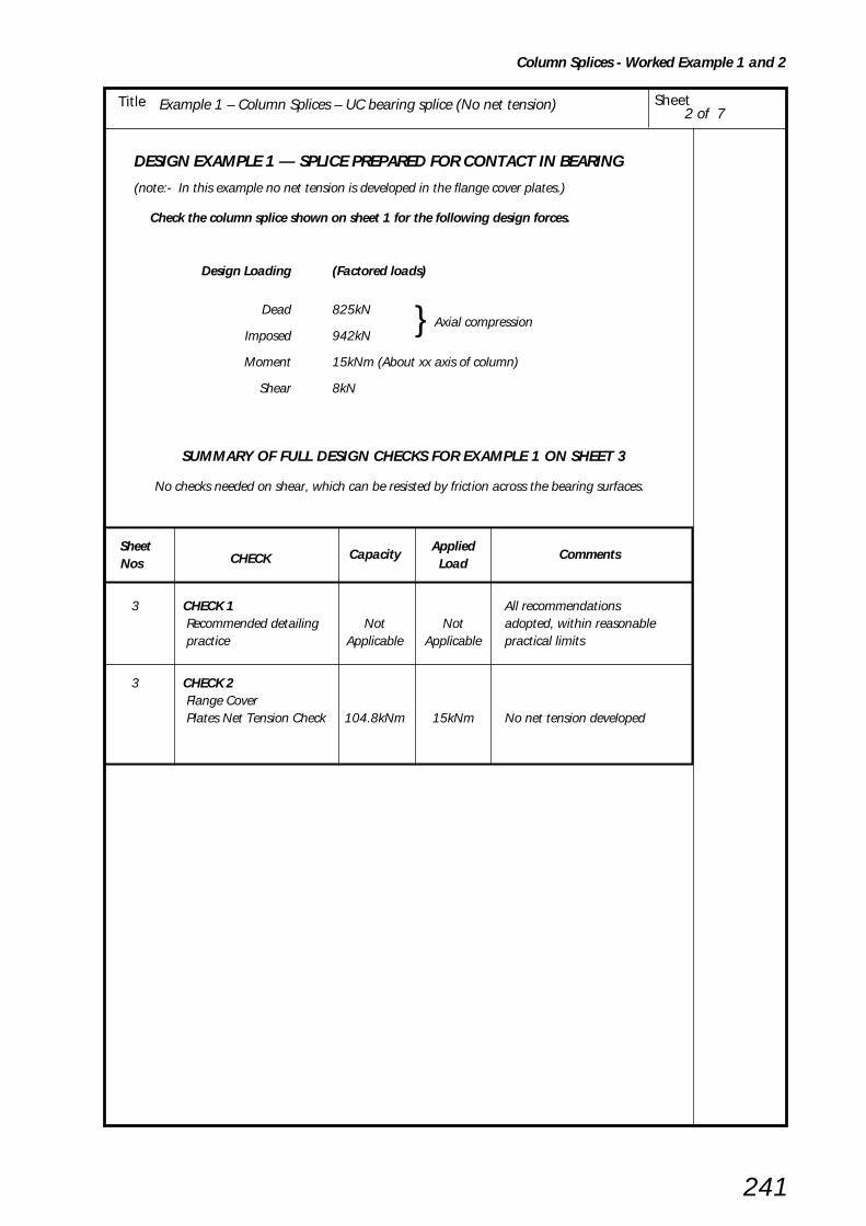
Example 1 – Column Splices – UC bearing splice (No net tension) SheetTitle
241
2 of 7
DESIGN EXAMPLE 1 — SPLICE PREPARED FOR CONTACT IN BEARING
(note:- In this example no net tension is developed in the flange cover plates.)
Check the column splice shown on sheet 1 for the following design forces.
Design Loading (Factored loads)
Dead 825kN } Axial compressionImposed 942kN
Moment 15kNm (About xx axis of column)
Shear 8kN
SUMMARY OF FULL DESIGN CHECKS FOR EXAMPLE 1 ON SHEET 3
No checks needed on shear, which can be resisted by friction across the bearing surfaces.
Sheet CHECK Capacity
AppliedComments
Nos Load
3 CHECK 1 All recommendations Recommended detailing Not Not adopted, within reasonable practice Applicable Applicable practical limits
3 CHECK 2 Flange Cover Plates Net Tension Check 104.8kNm 15kNm No net tension developed
Column Splices - Worked Example 1 and 2

Example 1 – Column Splices – UC bearing splice (No net tension) SheetTitle
242
3 of 7
CHECK 1: Recommended detailing practice
External flange cover plates
Projection, Lfp ≥ B1 and 225 = 254.6 and 225 Say 250mm Acceptable
Width, Wfp ≥ B1 = 254.6 Say 250mm Acceptable
Note: Maximum vertical bolt spacing p = 14t, i.e. minimum thickness is p/14 BS 5950-1
T1 p Cl 6.2.1.2
Thickness ≥ –– and 10 and –– 2 14
14.2 160= –––– and 10 and –––
2 14
= 7.1 and 10 and 11.4 Say 12mm ∴ O.K.
D2 – D1 314.5 – 254.1Packs, tpa = –––––––– = ––––––––––––
2 2
= 30.2 Say 30mm Acceptable
Division Plate
Thickness ≥ [(D2 – 2T2) – (D1 – 2T1)] x 0.5
= [(314.5 – (2 x 18.7)) – (254.1 – (2 x 14.2))] x 0.5
= 25.7 Say 25mm Acceptable
Web cleats
Use 90 x 90 x 8 Angles to accommodate M20 bolts in opposite positions on adjoining legs
Length ≥ 0.5 D1 = 0.5 x 254.1 = 127 Say 150mm ∴ O.K.
t2 – t1 12.0 – 8.6Packs tpa = –––––– = –––––––––
2 2
= 1.7 Say 2mm ∴ O.K.
(Alternatively omit packs and provide slotted holes in cleats)
CHECK 2: Flange cover plates
Net Tension Check
Fcd D Basic requirement for no net tension: M < ––––––
2
Fcd D 825 x 254.1 ––––– = –––––––––– = 104.8kNm 2 2 x 10³
M = 15kNm < 104.8kNm
Tension does not occur and the details derived in CHECK 1
∴ O.K.
Column Splices - Worked Example 1 and 2
can be adopted without further investigation.
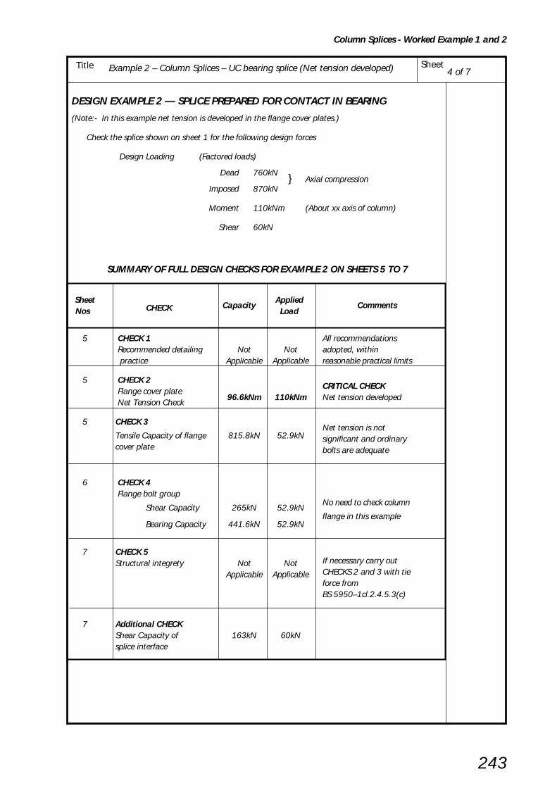
Example 1 – Column Splices – UC bearing splice (No net tension) SheetTitle
243
DESIGN EXAMPLE 2 — SPLICE PREPARED FOR CONTACT IN BEARING
(Note:- In this example net tension is developed in the flange cover plates.)
Check the splice shown on sheet 1 for the following design forces
Design Loading (Factored loads)
Dead 760kN } Axial compression
Imposed 870kN
Moment 110kNm (About xx axis of column)
Shear 60kN
4 of 7Example 2 – Column Splices – UC bearing splice (Net tension developed)
SUMMARY OF FULL DESIGN CHECKS FOR EXAMPLE 2 ON SHEETS 5 TO 7
Sheet CHECK Capacity
AppliedComments
Nos Load
5 CHECK 1 All recommendations Recommended detailing Not Not adopted, within practice Applicable Applicable reasonable practical limits
5 CHECK 2 Flange cover plate
CRITICAL CHECK
Net Tension Check96.6kNm 110kNm Net tension developed
5 CHECK 3
Tensile Capacity of flange 815.8kN 52.9kNNet tension is not
cover platesignificant and ordinarybolts are adequate
6 CHECK 4 Flange bolt group
Shear Capacity 265kN 52.9kNNo need to check column
Bearing Capacity 441.6kN 52.9kNflange in this example
7 CHECK 5Structural integrety Not Not If necessary carry out
Applicable Applicable CHECKS 2 and 3 with tieforce fromBS 5950–1cl.2.4.5.3(c)
7 Additional CHECKShear Capacity of 163kN 60kNsplice interface
Column Splices - Worked Example 1 and 2
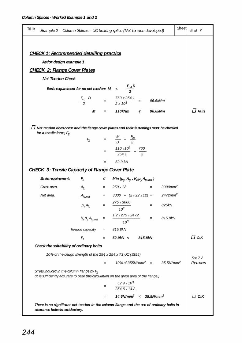
Example 1 – Column Splices – UC bearing splice (No net tension) SheetTitle
244
CHECK 1: Recommended detailing practice
As for design example 1
CHECK 2: Flange Cover Plates
Net Tension Check
Fcd D Basic requirement for no net tension: M < ––––
2
Fcd D 760 x 254.1 –––––– = –––––––– = 96.6kNm
2 2 x 10³
M = 110kNm <| 96.6kNm ∴∴∴∴∴ Fails
∴∴∴∴∴ Net tension does occur and the flange cover plates and their fastenings must be checked for a tensile force, F2
M Fcd F2 = ––– – ––– D 2
110 x 103 760= –––––––– – ––––
254.1 2
= 52.9 kN
CHECK 3: Tensile Capacity of Flange Cover Plate
Basic requirement: F2 ≤ Min (py Afp , Ke py Afp.net )
Gross area, Afp = 250 x 12 = 3000mm2
Net area, Afp.net = 3000 – (2 x 22 x 12) = 2472mm2
275 x 3000 py Afp = –––––––––– = 825kN
103
1.2 x 275 x 2472Ke py Afp.net = ––––––––––––––– = 815.8kN
103
Tension capacity = 815.8kN
F2 = 52.9kN < 815.8kN ∴∴∴∴∴ O.K.
Check the suitability of ordinary bolts.
10% of the design strength of the 254 x 254 x 73 UC (S355) See 7.2
= 10% of 355N/mm2 = 35.5N/mm2 Fasteners
Stress induced in the column flange by F2(it is sufficiently accurate to base this calculation on the gross area of the flange.)
52.9 x 103= ––––––––––
254.6 x 14.2
= 14.6N/mm2 < 35.5N/mm2 ∴ O.K.
There is no significant net tension in the column flange and the use of ordinary bolts inclearance holes is satisfactory.
5 of 72Example 2 – Column Splices – UC bearing splice (Net tension developed)
Column Splices - Worked Example 1 and 2

Example 1 – Column Splices – UC bearing splice (No net tension) SheetTitle
245
CHECK 4: Flange bolt group
Shear Capacity of Bolt Group
Basic requirement: F2 ≤ Reduction Factor x Σ Σ Σ Σ Σ Ps
Single shear capacity,M20 8.8 bolt Ps = 91.9kN
For top pair of bolts Ps = min (91.9 , 0.5 e tfp pbs )
0.5 x 40 x 12 x 4600.5 e tfp pbs = –––––––––––––––––
103
= 110.4kN
∴ Ps = 91.9kN
5500 – Lj 9dReduction Factor = min ( ––––––––– , ––––––––– , 1)
5000 8d + 3tpa
9d 9 x 20 –––––––––– = ––––––––––––––– 8d + 3tpa (8 x 20) + (3 x 30)
= 0.72
Joint length, Lj = 160mm < 500mm
Therefore there is no long joint effect.
Total shear capacity = Reduction Factor x Σ Ps
= 0.72 x 4 x 91.9
= 265kN
F2 = 52.9 < 265kN ∴ O.K.
Bearing Capacity
Basic requirement: Ft ≤ Σ Σ Σ Σ Σ Pbs
Bearing capacity for one bolt, Pbs = d tfp pbs
20 x 12 x 460= ––––––––––––
103
= 110. 4kN
For top pair of bolts, Pbs = min ( d tfp pbs , 0.5e tfp pbs )
Total bearing capacity, ΣPbs = 4 x 110.4
= 441. 6kN
F2 = 52.9 < 441.6kN ∴ O.K.
The column flange is thicker and of a higher grade of steel than the flange cover plate and istherefore adequate in bearing.
Note: The capacity of the flange cover plate, 265kN (i.e. minimum of CHECKS 3 and 4) can beobtained from Table H.33 in the yellow pages in lieu of applying CHECKS 3 and 4. When usingthe tables it is still necessary to investigate the suitability of ordinary bolts (CHECKS 2 and 3)and the adequacy of the column flange in bearing (CHECK 4).
6 of 72Example 2 – Column Splices – UC bearing splice (Net tension developed)
Flange cover plate
e = 40
L = 160j
Bolt capacitiesfrom
Yellow pagesTable H.49
pbs fromBS 5950-1Table 32
pbs fromBS 5950-1Table 32
Column Splices - Worked Example 1 and 2

Example 1 – Column Splices – UC bearing splice (No net tension) SheetTitle
246
CHECK 5: Structural Integrity of Splice
If it is necessary to comply with structural integrity requirements, then CHECKS 3 and 4 should becarried out with:
F2 = Ftie /2
based on the conservative assumption that the tie force is resisted by the flange cover plates.
Ftie is the tensile force obtained from BS 5950-1, clause 2.4.5.3(c).
Additional CHECK : Horizontal shear Capacity of Splice Interface
For a bearing type splice, any horizontal shear Fv is assumed to be resisted by friction acrossthe splice interface.
Basic requirement: Fv ≤≤≤≤≤ shear capacity of splice interface
The coefficient of friction µf for a steel to steel interface depends upon the surface condition ofthe steel and on any coatings provided.
Conservatively, for steel with no surface treatment, and with complete mill scale, the coefficientof friction, µf may be taken as 0.20.
Shear capacity of splice interface = Vertical load x Coefficient of friction
M FcdVertical load with coexistent shear = –– + –––D 2
110 x 103 760= –––––––– + ––––
254 2
= 433 + 380
= 813kN
Shear capacity of splice interface = 813 x 0.20
= 163kN
Fv = 60kN < 163kN
Therefore the splice detail is adequate.
7 of 7Example 2 – Column Splices – UC bearing splice (Net tension developed)
∴ O.K.
ECCS Pub
No. 37[33]
Column Splices - Worked Example 1 and 2

Example 3 – Column Splices – UC Non-bearing Splice SheetTitle
Column Splices - Worked Example 3
247
BCSA
CALCULATIONSHEET
Calcs by
Title
Client
Checked by Date
Job No SheetJoints in Steel Construction - Simple Connections
Example 3 – Column Splices - UC Non-bearing splice
SCI/BCSA Connections Group
RS AM May 2002
1 of 7
DESIGN EXAMPLE 3 – NON BEARING COLUMN SPLICE
Design Information:
Flange cover plates: 2/250 x12 x 690
Flange packs: 2/250 x 30 x 340
Web cover plates: 2/150 x 8 x 350
Web packs: 2/150 x 2 x 170
Bolts: M24 grade 8. 8
Fittings material: S275 steel
501069
0
Lfp
Lfp
250
15050 50
254 x 254 x 73 UC(S355 steel)
305 x 305 x 118 UC(S355 steel)
5010 gap
50
35 3580
150
50
80
80
80
50
50
80
80
80
80
40
80
40

Example 3 – Column Splices – UC Non-bearing Splice SheetTitle
Column Splices - Worked Example 3
248
Check the column splice shown on sheet 1 for the following design forces.
Design Loading (factored loads)
Dead 825kN} axial compression
Imposed 942kN
Moment 15kNm (About xx axis of column)
Shear 8kN (Resisted by web cover plates)
Tie force (structural lntegrity) 400kN Load from floor below splice
SUMMARY 0F FULL DESIGN CHECKS FOR EXAMPLE 3
Sheet CHECK Capacity Applied
CommentsNos kN kN
3 CHECK 1 All recommendationsRecommended detailing Not applicable Not applicable adopted within reasonablepractice practical limits.
3 CHECK 2Flange cover plates No net tension Axial Capacity 825 744
4 CHECK 3Flange Bolt Group Shear capacity 813 744
Bearing Capacity 1060 744
5 CHECK 4Web cover plates
Axial Capacity 330 199
5,6 CHECK 5Web Bolt GroupShear capacity 411 199
Bearing Capacity (web cover plate) 324 199
Bearing capacity (column web) 454 398 CRITICAL CHECK
7 CHECK 6Structural Integrity
Axial Capacity of Flange Cover Plate 784 200 CRITICAL CHECKfor Structural integrity
2 of 7

Example 3 – Column Splices – UC Non-bearing Splice SheetTitle
Column Splices - Worked Example 3
249
3 of 7
CHECK 1: Recommended detailing practice
Bolt diameter ≥ 3/4 thickness of packing either side
24mm > 0.75 x 30 = 22.5mm ∴ O.K.
If this is found to be impracticable then the packs may be fillet welded to the column flanges and thischeck omitted.
All other requirements are satisfied as in design example 1.
CHECK 2: Flange Cover Plate
Axial Capacity of flange cover plates
Basic requirement for compression:
F1 ≤ py Afp
M AfConservatively, F1 = –– + Fc [––– ] D A
Afp = area of flange cover plate
Af = area of one flange of smaller column
A = total area of smaller column
15 x 103 254 x 14.2F1 = ––––––– + (825 + 942) [––––––––– ]
254 93.1 x 102
= 744kN compression
Compression capacity = py Afp
275 x 250 x 12= ––––––––––––– = 825kN
103
F1 = 744kN < 825kN ∴ O.K.
M AfCheck for tension, F2 = ––– – Fcd [––– ] D A
15 x 103 254 x 14.2= ––––––– – 825 [ –––––––––– ]
254 93.1 x l02
= – 261kN
This indicates a net compression of 261kN
Therefore tension is not present.
Assuming that slip is acceptable, and since there is no net tension,
the use of ordinary bolts is satisfactory.

Example 3 – Column Splices – UC Non-bearing Splice SheetTitle
Column Splices - Worked Example 3
250
CHECK 3: Flange Bolt Group
Shear Capacity of Bolt Group
Basic requirement: F1 ≤ Reduction Factor x ΣΣΣΣΣPs
Single shear capacityfor an M24 8.8 bolt Ps = 132kN
For top pair of bolts Ps = min (132 , 0.5 e tfp pbs)
0.5 x 50 x 12 x 460= ––––––––––––––––
103
= 138kN > 132kN
∴ Ps = 132kN
5500 – Lj 9dReduction Factor = min (–––––––– , ––––––– , 1)
5000 8d + 3tpa
9d 9 x 24––––––– = ––––––––––––––––––8d + 3tpa (8 x 24) + (3 x 30)
= 0.77
Joint length, Lj = 3 x 80 = 240mm < 500mm
Therefore there is no long joint effect.
Total shear capacity = Reduction Factor x ΣPs
= 0.77 x 8 x 132
= 813kN > 744kN
F1 = 744kN < 813kN
Bearing Capacity
Basic requirement: F1 ≤ ΣΣΣΣΣPbs
Bearing capacity for one bolt Pbs = d tfp pbs
24 x 12 x 460= –––––––––––
103
= 132.5kN
For top pair of bolts Pbs = min ( d tfp pbs , 0.5e tfp pbs )
∴ Pbs = 132.5kN
Total bearing capacity, ΣPbs = 8 x 132.5
= 1060kN
F1 = 744kN < 1060kN
The column flange, being 14.2mm thick and of S355 steel is also adequate in bearing.
4 of 7
bolt capacitiesfrom
Yellow pagesTable H.49
pbs fromBS 5950-1Table 32
pbs fromBS 5950-1Table 32
∴ O.K.
∴ O.K.

Example 3 – Column Splices – UC Non-bearing Splice SheetTitle
Column Splices - Worked Example 3
251
CHECK 4: Web cover plate
Axial capacity
F3Basic requirement: –— ≤ py Awp2
Fc AwConservatively, F3 = ––––––– A
Fc = Axial load due to factored dead & imposed loads
A = Total area of upper column
Aw = Area of web of upper column = A – 2Af
Af = Flange area of upper column
(825 + 942)[(93.1 x 10²) – (2 x 254 x 14.2)] F3 = ––––––––––––––––––––––––––––––––––––––
93.1 x l02
= 398kN
Compression capacity = py Awp
275 x 150 x 8= ––––––––––––
103
= 330kN
F3––– = 199kN < 330kN2
CHECK 5: Web cover plate bolt group
Shear capacityF3
Basic requirement: –– < ΣΣΣΣΣ Ps2
For an M24 8.8 bolt, Ps = 132kN as before CHECK 3
For top pair of bolts (end distance = 40mm),
Ps = min ( 132 , 0.5e twp pbs )
0.5 x 40 x 8 x 4600.5e twp pbs = –––––––––––––––
103
= 73.6kN
∴ Ps = 73.6kN
Total shear capacity = Σ Ps
= (2 x 132.4) + (2 x 73.6) = 411kN
F3–– = 199KN < 411kN2
5 of 7
pbs fromBS 5950-1Table 32
∴ O.K.
∴ O.K.
Column
Cover plate
F3F3
F3F32
F32
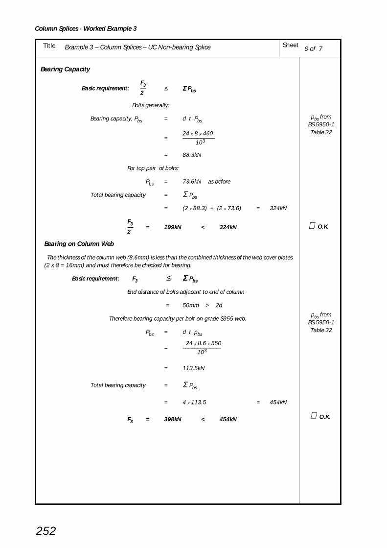
Example 3 – Column Splices – UC Non-bearing Splice SheetTitle
Column Splices - Worked Example 3
252
Bearing Capacity
F3 Basic requirement: –– ≤ Σ Σ Σ Σ Σ Pbs 2
Bolts generally:
Bearing capacity, Pbs = d t Pbs
24 x 8 x 460= –––––––––––
103
= 88.3kN
For top pair of bolts:
Pbs = 73.6kN as before
Total bearing capacity = Σ Pbs
= (2 x 88.3) + (2 x 73.6) = 324kN
F3–– = 199kN < 324kN2
Bearing on Column Web
The thickness of the column web (8.6mm) is less than the combined thickness of the web cover plates(2 x 8 = 16mm) and must therefore be checked for bearing.
Basic requirement: F3 ≤ Σ Σ Σ Σ Σ Pbs
End distance of bolts adjacent to end of column
= 50mm > 2d
Therefore bearing capacity per bolt on grade S355 web,
Pbs = d t pbs
24 x 8.6 x 550= –––––––––––––
103
= 113.5kN
Total bearing capacity = Σ Pbs
= 4 x 113.5 = 454kN
F3 = 398kN < 454kN
6 of 7
pbs fromBS 5950-1Table 32
∴ O.K.
pbs fromBS 5950-1Table 32
∴ O.K.
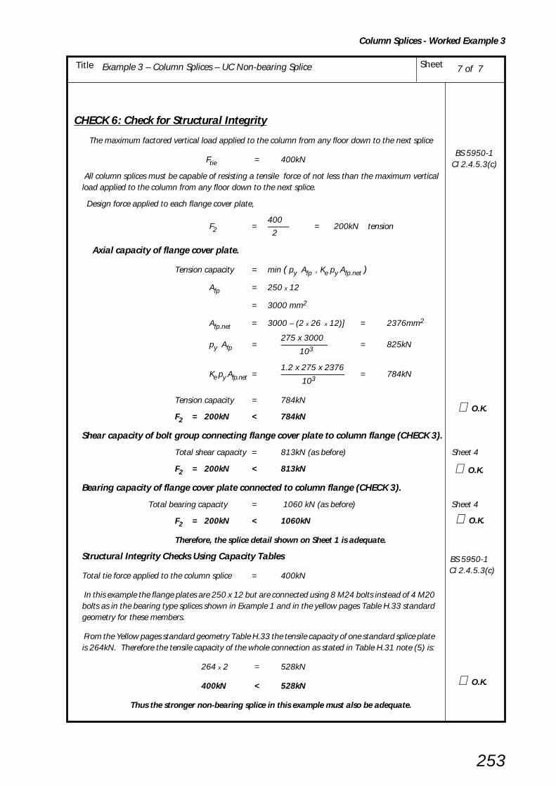
Example 3 – Column Splices – UC Non-bearing Splice SheetTitle
Column Splices - Worked Example 3
253
CHECK 6: Check for Structural Integrity
The maximum factored vertical load applied to the column from any floor down to the next splice
Ftie = 400kN
All column splices must be capable of resisting a tensile force of not less than the maximum verticalload applied to the column from any floor down to the next splice.
Design force applied to each flange cover plate,
400F2 = ––––– = 200kN tension
2
Axial capacity of flange cover plate.
Tension capacity = min ( py Afp , Ke py Afp.net )
Afp = 250 x 12
= 3000 mm2
Afp.net = 3000 – (2 x 26 x 12)] = 2376mm2
275 x 3000py Afp = ––––––––––– = 825kN
103
1.2 x 275 x 2376Ke py Afp.net = ––––––––––––––– = 784kN
103
Tension capacity = 784kN
F2 = 200kN < 784kN
Shear capacity of bolt group connecting flange cover plate to column flange (CHECK 3).
Total shear capacity = 813kN (as before) Sheet 4
F2 = 200kN < 813kN
Bearing capacity of flange cover plate connected to column flange (CHECK 3).
Total bearing capacity = 1060 kN (as before) Sheet 4
F2 = 200kN < 1060kN
Therefore, the splice detail shown on Sheet 1 is adequate.
Structural Integrity Checks Using Capacity Tables BS 5950-1
Total tie force applied to the column splice = 400kN Cl 2.4.5.3(c)
In this example the flange plates are 250 x 12 but are connected using 8 M24 bolts instead of 4 M20bolts as in the bearing type splices shown in Example 1 and in the yellow pages Table H.33 standardgeometry for these members.
From the Yellow pages standard geometry Table H.33 the tensile capacity of one standard splice plateis 264kN. Therefore the tensile capacity of the whole connection as stated in Table H.31 note (5) is:
264 x 2 = 528kN
400kN < 528kN
Thus the stronger non-bearing splice in this example must also be adequate.
7 of 7
∴ O.K.
∴ O.K.
∴ O.K.
∴ O.K.
BS 5950-1Cl 2.4.5.3(c)

Example 4 - Splices - RHS tension splice SheetTitle
RHS Tension Splices - Worked Example 4
254
BCSA
CALCULATIONSHEET
Calcs by
Title
Client
Checked by Date
Job No SheetJoints in Steel Construction - Simple Connections
Example 4 - Splices - RHS tension splice
SCI/BCSA Connections Group
RS AW May 2002
1 of 5
DESIGN EXAMPLE 4 – RHS TENSION SPLICE
Check the following connection for the design forces shown:
Total number of bolts N = 6
Design Information:
End Plates: 280 x 310 x 25
Bolts: M24 8.8
Material: S275 steel
Weld: 12mm fillet
800kN
800kN
25 25
= 50
50
= 280 = 90
= 50
= 90
200 x 100 x 8.0 Grade S275 RHS
200 x 100 x 8.0 Grade S275 RHS
55
D p
e 3
e 3
p
p
e 2 e 1
B = 310 p

Example 4 - Splices - RHS tension splice SheetTitle
RHS Tension Splices - Worked Example 4
255
2 of 5
SUMMARY 0F FULL DESIGN CHECKS FOR EXAMPLE 4
Sheet CHECK
Capacity AppliedCommentsNos kN kN
3 CHECK 1 Recommended detailing Not Not All recommendations practice Applicable Applicable adopted
3 CHECK 2 Complete end plate yielding - - Not applicable due to end plate
thickness limitations
3 CHECK 3 Bolt failure with end plate yielding 850 800 CRITICAL CHECK
4 CHECK 4 Bolt Group - Tension capacity 1188 800
5 CHECK 5 Weld
- Tension capacity 924 800 Full strength welds
5 CHECK 6 Member - Tension capacity 1232 800
CONNECTION DESIGN USING CAPACITY TABLES FROM YELLOW PAGES
Yellow pages200 X 100 X 8.0 RHS Grade S275 Standard connection Table H.38
Total number of bolts = 6
End plate thickness = 25mm
Tying capacity = 817 kN See Table H.34 note (2)
Applied force = 800 kN
800kN < 817kN ∴ ∴ ∴ ∴ ∴ O.K.
Note: The capacity from Table H.38 is conservatively based on the thickest sectionin the range.
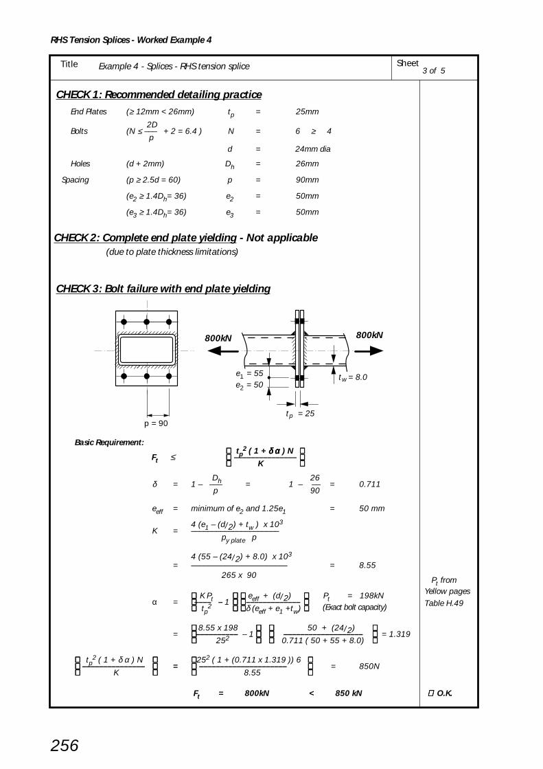
Example 4 - Splices - RHS tension splice SheetTitle
RHS Tension Splices - Worked Example 4
256
3 of 5
CHECK 1: Recommended detailing practice End Plates (≥ 12mm < 26mm) tp = 25mm
2D Bolts (N ≤ ––– + 2 = 6.4 ) N = 6 ≥ 4
pd = 24mm dia
Holes (d + 2mm) Dh = 26mm
Spacing (p ≥ 2.5d = 60) p = 90mm
(e2 ≥ 1.4Dh= 36) e2 = 50mm
(e3 ≥ 1.4Dh= 36) e3 = 50mm
CHECK 2: Complete end plate yielding - Not applicable (due to plate thickness limitations)
CHECK 3: Bolt failure with end plate yielding
Basic Requirement: tp
2 ( 1 + δ α δ α δ α δ α δ α ) N Ft ≤ –––––––––––––––
K
Dh 26δ = 1 – ––– = 1 – –– = 0.711 p 90
eeff = minimum of e2 and 1.25e1 = 50 mm
4 (e1 – (d/2) + tw ) x 103K = –––––––––––––––––––––
py plate p
4 (55 – (24/2) + 8.0) x 103
= ––––––––––––––––––––––– = 8.55 265 x 90
K Pt eeff + (d/2) Pt = 198kNα = –––– – 1 –––––––––––––
(Exact bolt capacity) tp2 δ (eeff + e1 +tw)
8.55 x 198 50 + (24/2) = –––––––––– – 1 ––––––––––––––––––– = 1.319
252 0.711 ( 50 + 55 + 8.0)
tp2 ( 1 + δ α ) N 252 ( 1 + (0.711 x 1.319 )) 6
––––––––––––––– = ––––––––––––––––––––– = 850N K 8.55
Ft = 800kN < 850 kN ∴∴∴∴∴ O.K.
p = 90
800kN 800kN
e = 55
2e = 50 1 t = 8.0 w
t = 25 p
Pt fromYellow pagesTable H.49

Example 4 - Splices - RHS tension splice SheetTitle
RHS Tension Splices - Worked Example 4
257
CHECK 4: Bolt failure
Basic Requirement for bolt tensile capacity:
Ft ≤ N Pt
N Pt = 6 x 198
= 1188 kN
Ft = 800kN ≤ 1188kN ∴ ∴ ∴ ∴ ∴ O.K
4 of 5
Pt fromYellow pagesTable H.49
800kN 800kN

Example 4 - Splices - RHS tension splice SheetTitle
RHS Tension Splices - Worked Example 4
258
5 of 5
CHECK 5: Welds
Basic Requirement for weld tensile capacity:(i) tw ≤ a (continuous full strenghth weld )
or
(ii) Ft ≤ 2 D a pw x 1.25
pw = design strength of weld = 220N/mm2
weld throat a = 0.7 s = 0.7 x 12mm = 8.4mm
(i) tw = 8.0mm ≤ 8.4mm
2 x 200 x 8.4 x 220 x 1.25 2 D a pw x 1.25 = –––––––––––––––––––––– = 924kN
103
(ii) Ft = 800kN < 924kN
CHECK 6: Member Capacity
Basic Requirement:
Ft ≤ A py
A = 44.8 cm2
py = 275 N/mm2
44.8 x 102 x 275A py = –––––––––––––––– = 1232kN
103
Ft = 800kN < 1232kN
s = 12mm FW
D = 200
B = 100
continuous weld
800kN 800kN
pw fromBS 5950 -1Table 37
∴∴∴∴∴O.K
∴∴∴∴∴O.K
py fromBS 5950 -1Table 9
∴∴∴∴∴O.K
Yellow pages
Table H.72
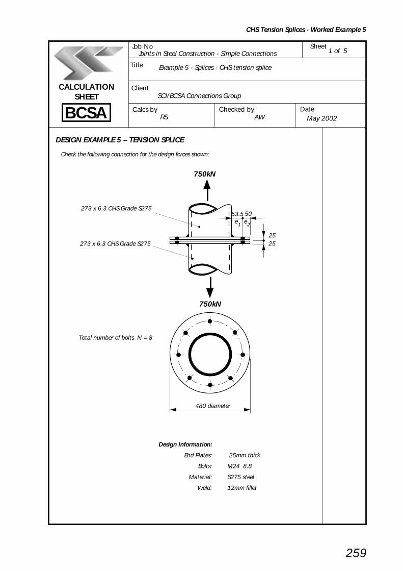
Example 5 - Splices - CHS tension splice SheetTitle
CHS Tension Splices - Worked Example 5
259
BCSA
CALCULATIONSHEET
Calcs by
Title
Client
Checked by Date
Job No SheetJoints in Steel Construction - Simple Connections
SCI/BCSA Connections Group
RS AW May 2002
1 of 5
DESIGN EXAMPLE 5 – TENSION SPLICE
Check the following connection for the design forces shown:
Design Information:
End Plates: 25mm thick
Bolts: M24 8.8
Material: S275 steel
Weld: 12mm fillet
Example 5 - Splices - CHS tension splice
750kN
750kN
25 25
480 diameter
273 x 6.3 CHS Grade S275
273 x 6.3 CHS Grade S275
50 e 1 e 2
53.5
Total number of bolts N = 8
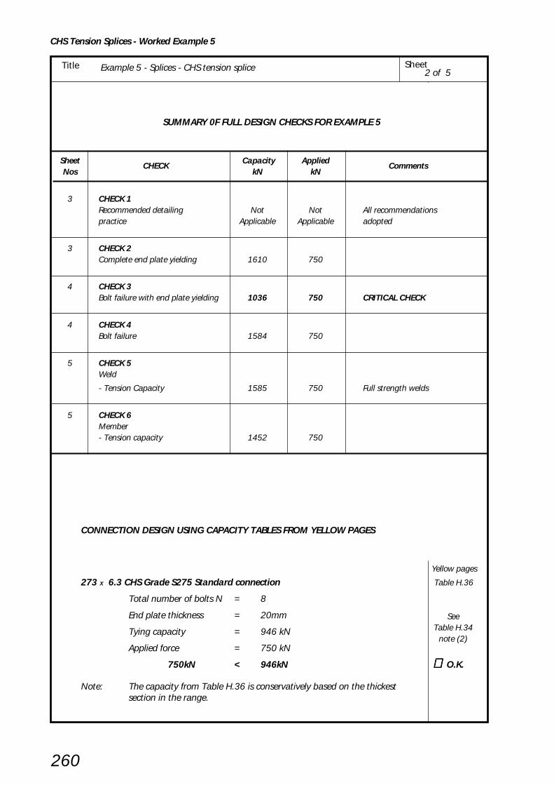
Example 5 - Splices - CHS tension splice SheetTitle
CHS Tension Splices - Worked Example 5
260
SUMMARY 0F FULL DESIGN CHECKS FOR EXAMPLE 5
Sheet CHECK
Capacity Applied Comments
Nos kN kN
3 CHECK 1 Recommended detailing Not Not All recommendations practice Applicable Applicable adopted
3 CHECK 2 Complete end plate yielding 1610 750
4 CHECK 3 Bolt failure with end plate yielding 1036 750 CRITICAL CHECK
4 CHECK 4 Bolt failure 1584 750
5 CHECK 5 Weld
- Tension Capacity 1585 750 Full strength welds
5 CHECK 6 Member - Tension capacity 1452 750
2 of 5
CONNECTION DESIGN USING CAPACITY TABLES FROM YELLOW PAGES
Yellow pages
273 X 6.3 CHS Grade S275 Standard connection Table H.36
Total number of bolts N = 8
End plate thickness = 20mm
Tying capacity = 946 kN
Applied force = 750 kN
750kN < 946kN ∴ ∴ ∴ ∴ ∴ O.K.
Note: The capacity from Table H.36 is conservatively based on the thickestsection in the range.
SeeTable H.34
note (2)

Example 5 - Splices - CHS tension splice SheetTitle
CHS Tension Splices - Worked Example 5
261
3 of 5
CHECK 1: Recommended detailing practice
End Plates tp = 25mm
Bolts d = 24mm dia
Holes Dh = 26mm
Spacing (≥ 2.5d = 60) p = 380 x π /8 (< 10d =240) = 149mm
Edge distance ( ≥ 1.4Dh = 36) e2 = 50mm
CHECK 2: Complete end plate yielding
Basic requirement:
tp2 py plate π f3Ft ≤ –––––––––––––
2
1 f3 = –– ( k3 + (k3
2 – 4 k1)0.5)
2k1
k1 = ln (r2 /r3) [ln = natural loge]
D 273r2 = –– + e1 = –––– + 53.5 = 190
2 2
D – tw 273 – 6.3r3 = ––––– = ––––––––– = 133.4
2 2
190k1 = ln ––––– = ln1.42 = 0.354
133.4
k3 = k1 + 2 = 0.354 + 2 = 2.354
1∴ f3 = –––––––– ( 2.354 + (2.3542 – 4 x 0.354)0.5)
2 x 0.354
= 6.19
252 x 265 x π x 6.19∴ Plate capacity = ––––––––––––––––– = 1610kN 2 x 10³
Ft = 750kN ≤ 1610 kN ∴ ∴ ∴ ∴ ∴ O.K.
750kN 750kN
t = 6.3 w
t = 25 p
e = 53.5 1
D = 273

Example 5 - Splices - CHS tension splice SheetTitle
CHS Tension Splices - Worked Example 5
262
CHECK 3: Bolt failure with end plate yielding
Basic requirement:
NPt Ft ≤ –––––––––––––––––––––––––––– 1 1 1 – –––– + ––––––––– [ln = natural loge] f3 f3 ln(r1/r2
)
Pt = Exact bolt capacity = 198kN
f3 = 6.19 CHECK 2
eeff = minimum of e2 and 1.25e1 = 50 mm
D 273r1 = –– + e1+ eeff = ––––– + 53.5 + 50 = 240mm
2 2
D 273r2 = ––– + e1 = ––––– + 53.5 = 190mm
2 2
240ln(r1/r2) = ln ––––– = ln 1.263 = 0.234
190
8 x 198∴ Bolt group capacity = ––––––––––––––––––––––––––––– = 1036kN 1 1 1 – –––– + ––––––––––– 6.19 6.19 x 0.234
Ft = 750kN < 1036 kN ∴ ∴ ∴ ∴ ∴ O.K.
CHECK 4: Bolt failure
Basic requirement for bolt tensile capacity:
Ft ≤ N Pt
N Pt = 8 x 198
= 1584 kN
Ft = 750kN ≤ 1584kN ∴ ∴ ∴ ∴ ∴ O.K
4 of 5
750kN
e = 53.5 1e = 50 2
t = 6.3 w
p = 139
750kN
Pt fromYellow pagesTable H.49
Pt fromYellow pagesTable H.49

Example 5 - Splices - CHS tension splice SheetTitle
CHS Tension Splices - Worked Example 5
263
5 of 5
CHECK 5: Welds
Basic requirement for weld tensile capacity:
(i) tw ≤ a (continuous full strenghth weld )
or
(ii) Ft ≤ π D a pw
pw = design strength of weld = 220N/mm2
weld throat a = 0.7 s = 0.7 x 12mm = 8.4mm
(i) tw = 6.3mm ≤ 8.4mm
π x 273 x 8.4 x 220 π D a pw = ––––––––––––––––– = 1585kN
103
(ii) Ft = 750kN < 1585kN
CHECK 6: Member Capacity
Basic requirement:
Ft ≤ A py
A = 52.8 cm2
py = 275 N/mm2
52.8 x 102 x 275A py = –––––––––––––––– = 1452kN
103
Ft = 750kN < 1452kN
e = 53.5 1 t = 6.3 w
D = 273mm
continuous weld
750kN750kN
pw fromBS 5950 -1 Table 37
∴∴∴∴∴O.K
∴∴∴∴∴O.K
py fromBS 5950 -1
Table 9
∴∴∴∴∴O.K
Yellow pagesTable H.70

264
8. COLUMN BASES
8. 1 INTRODUCTION
Typical column bases as shown in Figure 8.1 consist of asingle plate fillet welded to the end of the column andattached to the foundation with four holding down bolts.The bolts are cast into the concrete base in location tubesor cones and are fitted with anchor plates to prevent pull-out. Bedding material is inserted in the space below theplate (see Figure 8.2).
Such column bases are usually assumed to be subject toaxial compression and shear only. However, uplift shouldbe considered for column bases in braced bays.
The base plate should be of sufficient size, stiffness andstrength to transmit the axial compressive force from thecolumn to the foundation through the bedding material,without exceeding the local bearing capacity of thefoundation.
Holding down systems are intended to meet the followingrequirements:
• In service they must transmit shear from the column tothe foundation;
• during erection they must be capable of stabilising thecolumn until other structural elements have beenerected;
• during construction they must resist uplift;
• in service they must resist uplift in braced bays.
For most columns in simple multistorey construction thistype of base is simple to fabricate and relatively inexpensive.Rarely will it be more economical to use thinner basesaugmented by stiffeners, an arrangement that has beenmore popular in the past.
As with column splices, column bases fall Into two maincategories:
• Bearing type: the loads are transferred in direct bearingfrom the column to the baseplate.
• Non-bearing type: the loads are transmitted via thewelds which have to be designed accordingly.
The bearing type is the normal connection used today.The non-bearing type often requires a large amount ofwelding.
There is no difference in the design procedure for thesetwo cases except that the weld between the column andthe base plate must be checked for the vertical loads in thenon-bearing case.
However, the two systems do have different implicationsfor the Steelwork Contractor. Ends prepared for contact inbearing can be achieved by providing a sawn cut end forthe column, and a base plate made from plates or wideflats up to 55mm thick. Such plates are normally assumedto have a flat surface and require no preparation for tightbearing. Material over this thickness may require machiningThe National Structural Steelwork Specificatlon[8] givesworkmanship details and all tolerances for both the bearingand non-bearing cases.
The way in which horizontal shear forces are transferred tothe foundation is uncertain. For further guidance see SCI-P207/95 [24] which suggests that generally, shear loadsless than 30% of the axial load may be resisted by friction.
Figure 8.1 Typical column bases

265
Column bases to braced bays may be required to dealwith relatively high shear loads. An attempt[34] to establisha design approach for holding down systems producedno general consensus, except strong statements that noreliance should be placed on the bedding material totransmit shear force. However, SCI-P207/95[24] givessome design guidance on the topic.
This publication does not present a design method fortransferring shear from the base plate to the foundation.It is noted however that it is common and successfulindustrial practice to use the holding down bolts of portalframes to resist the substantial shear forces that exist inthat structural form.
For bearing surfaces, shear between the column end andthe base plate can be transmitted by friction or thenominal weld between the column and the base plate.For non-bearing surfaces, the weld should be designed totransmit the shear.
8.2 PRACTICAL CONSIDERATIONS
Column shaftThe normal preparation for a bearing type connection isfor the column section to be sawn square to its axis. Agood quality saw in proper working order is adequate forthis purpose. It must be emphasised that direct bearingdoes not necessitate the machining or end milling of thecolumn ends. Guidance on the allowable tolerancebetween bearing surfaces can be found in BS 5950-2[1] orthe National Structural Steelwork Specification[8].
Base platesBase plates will usually be flame cut or sawn from S275rather than S355 plate.
The portion of base plate in contact with the column shaftshould be flat within a deviation of 0.75mm. It will befound that most plates have a sufficiently flat bearingsurface without machining or cold pressing.
WeldsFor bearing type bases the main function of the weld is tohold the column shaft securely in position on the baseplate.
This being the case, only 6mm or 8mm fillet welds aregenerally required, usually run along the outside of theflanges and for a short distance either side of the web. Fullprofile welds will usually only be used for non-bearingbases or if additional strength is needed during erectionor as an anti-corrosion measure.
Because of the thickness of the parts to be joined,consideration must be given to hydrogen cracking, whichcan be a problem during welding thick material. Table 8.1gives values for the maximum combined plate thicknessesusing a range of fillet welds and different types of electrode.As can be seen, as long as 8mm welds or low hydrogenelectrodes are used, then cracking can be avoided withouthaving to resort to the expense of pre-heating.
It should be noted that welding guidance rules given hererefer to single pass manual metal arc welding only.More guidance on other welding procedures is given inBS EN 1011[13].
Holding down boltsHolding down bolts are normally manufacturerd inaccordance with BS 7419[35] which covers:
• bolts with square head and neck, and
• bolts with hexagon head and round neck.
For the square head type, bolt rotation during tighteningis prevented by placing the square neck in a square holein the anchor plate. For the hexagon head type, a small‘keep’ flat is usually welded to the underside of the plateto bear against one of the hexagonal head flats.
The embedded length of the bolt in the concrete willusually be in the region of 16 to 18 bolt diameters. Thethread length must allow for tolerances and should be100mm plus the bolt diameter.
Holding down bolts are usually provided in grade 4.6material. For lighter construction, M20 H.D bolts are oftenused, although M24 bolts are recommended for bases upto 50mm thick, increasing to M36 for plates over 50mmthick.
Although bolts are normally used in the non-coatedcondition, they can be supplied:
• electroplated to BS 7371-3[36];
• galvanized to BS 7371-6[37];
• sherardized to BS 7371-8[38].
Dimensions of holding down bolts to BS 7419[35] areIncluded with the detailing information in the yellowpages, table H.63
Column Bases - Practical Considerations

266
Figure 8.2 Column base holding down bolts
Column Bases - Practical Considerations
Notes: 1 The table covers fillet welds made using single run welds.
2 Electrodes are to BS EN 499: 1995[39] coating types R and B only.
3 For other Carbon Equivalent Values (CEV) and other processes refer to BS EN 1011[13].
4 If combined thickness is greater than given in the table, preheat will be required in accordance with BS EN 1011.
5 ∞ Signifies that there is no limit on the combined thickness.
Table 8.1 Maximum combined thicknesses for manual metal arc welding to avoid preheating
tp = Base plate thickness
tw = Column web thickness
T = Column flange thickness
Combined thickness = 2tp + tw or
= 2tp + T
Fillet Max combined thickness (mm)
Steel Maxweld
to avoid preheat relative
grade* C E V
size hydrogen scale (see BS EN 1011)[13]
A B C D
S275 0.40 6 70 ∞ ∞ ∞8 ∞ ∞ ∞ ∞
S355 0.45 6 50 60 70 ∞8 70 ∞ ∞ ∞
* the higher grade of the base plate and the column
t T
t ptp
w
Base plate
Bedding space
Holding down bolts Anchor plates
Location tubeor equivalent
Top of concretefoundation
Optional grout hole
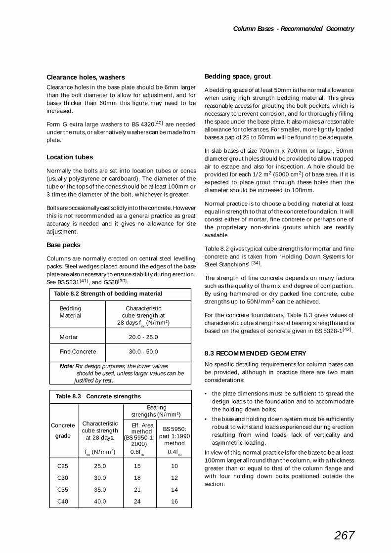
267
Clearance holes, washersClearance holes in the base plate should be 6mm largerthan the bolt diameter to allow for adjustment, and forbases thicker than 60mm this figure may need to beincreased.
Form G extra large washers to BS 4320[40] are neededunder the nuts, or alternatively washers can be made fromplate.
Location tubes
Normally the bolts are set into location tubes or cones(usually polystyrene or cardboard). The diameter of thetube or the tops of the cones should be at least 100mm or3 times the diameter of the bolt, whichever is greater.
Bolts are occasionally cast solidly into the concrete. Howeverthis is not recommended as a general practice as greataccuracy is needed and it gives no allowance for siteadjustment.
Base packs
Columns are normally erected on central steel levellingpacks. Steel wedges placed around the edges of the baseplate are also necessary to ensure stability during erection.See BS 5531[41], and GS28[30].
Table 8.2 Strength of bedding material
Bedding CharacteristicMaterial cube strength at
28 days fcu (N/mm2)
Mortar 20.0 - 25.0
Fine Concrete 30.0 - 50.0
Note: For design purposes, the lower valuesshould be used, unless larger values can be
justified by test.
Bedding space, grout
A bedding space of at least 50mm is the normal allowancewhen using high strength bedding material. This givesreasonable access for grouting the bolt pockets, which isnecessary to prevent corrosion, and for thoroughly fillingthe space under the base plate. It also makes a reasonableallowance for tolerances. For smaller, more lightly loadedbases a gap of 25 to 50mm will be found to be adequate.
In slab bases of size 700mm x 700mm or larger, 50mmdiameter grout holes should be provided to allow trappedair to escape and also for inspection. A hole should beprovided for each 1/2 m2 (5000 cm2) of base area. If it isexpected to place grout through these holes then thediameter should be increased to 100mm.
Normal practice is to choose a bedding material at leastequal in strength to that of the concrete foundation. It willconsist either of mortar, fine concrete or perhaps one ofthe proprietary non-shrink grouts which are readilyavailable.
Table 8.2 gives typical cube strengths for mortar and fineconcrete and is taken from ‘Holding Down Systems forSteel Stanchions’ [34].
The strength of fine concrete depends on many factorssuch as the quality of the mix and degree of compaction.By using hammered or dry packed fine concrete, cubestrengths up to 50N/mm2 can be achieved.
For the concrete foundations, Table 8.3 gives values ofcharacteristic cube strengths and bearing strengths and isbased on the grades of concrete given in BS 5328-1[42].
8.3 RECOMMENDED GEOMETRY
No specific detailing requirements for column bases canbe provided, although in practice there are two mainconsiderations:
• the plate dimensions must be sufficient to spread thedesign loads to the foundation and to accommodatethe holding down bolts;
• the base and holding down system must be sufficientlyrobust to withstand loads experienced during erectionresulting from wind loads, lack of verticality andasymmetric loading.
In view of this, normal practice is for the base to be at least100mm larger all round than the column, with a thicknessgreater than or equal to that of the column flange andwith four holding down bolts positioned outside thesection.
Column Bases - Recommended Geometry
Table 8.3 Concrete strengths
Bearingstrengths (N/mm2)
Concrete Characteristic Eff. AreaBS 5950:cube strength method
part 1:1990grade at 28 days. (BS 5950-1:method2000)
fcu (N/mm2) 0.6fcu 0.4fcu
C25 25.0 15 10
C30 30.0 18 12
C35 35.0 21 14
C40 40.0 24 16

268
8.4 DESIGN
Two design procedures are given for slab column bases:
• the effective area method. (BS5950-1:2000)
• the BS 5950: Part 1:1990 method
The effective area method is marginally more efficientover the full range of rolled sections used as columns andthe design procedure is fully described in Section 8.5.
Although not in the current standards, the BS 5950: Part1:1990 method is dealt with in Appendix E. This methodshould only be used to obtain the initial plate dimensions.
Column bases subject to both axial load and an overturningmoment have to take into account the effect of tension onone side of the base. This treatment can be found inMoment Connections[24] which is another design guide inthis series.
Effective area methodIn this method it is assumed that the bearing pressure onthe effective area is uniform and that the plate acts as asimple cantilever around the perimeter of the section. Theeffective area is illustrated in Figure 8.3 with respect to arolled I section.
(i) Effective area (ii) Effective area with overlap (iii) Revised effective area
Figure 8.3 Calculated effective area for a rolled section
Figure 8.4 Calculated effective area for RHS & CHS sections
The projection width c, shown in (i) is the minimum thatis needed to keep the base pressure below the limitingbearing strength which in this case is taken as 0.6 fcu,where fcu is the characteristic cube strength of theconcrete base or the bedding material, whichever is less(See Tables 8.2 and 8.3).
In some circumstances, it can be found that the projection,c becomes so large that the strips overlap between thecolumn flanges as shown in (ii).
i.e. c > (D-2T)/2
This clearly can not be allowed to happen and c must betherefore recalculated on the basis of the effective areashown in (iii).
The design is similar for the slab bases for tubular columnsand is illustrated for RHS and CHS columns in Figure 8.4.Of course, if the internal projection overlaps the centre ofthe plate, a readjusted effective area must be recalculatedin a similar manner to that for the rolled section.
Column Bases - Design
2c + t
2c + t
Outstand, c
t = Wall thickness
2c + t
t = Wall thickness
Overlap
2c + T
2c + t
Projection, c
T = Flange thickness
t = Web thickness
c
Overlap
D – 2T
D = depth of column
c
c
c
B +
2c
D + 2c
B = width of column
2c + t
t = Wall thickness
Square or circularbase plate

269
The effective area method, does not have the limitations ofBS 5950: Part 1:1990 on plate thickness ≥ column flangethickness and plate design strength pyp ≤ 270 N/mm2.The bearing strengths for the two methods are 0.6 fcu and0.4 fcu. Typical values for grout and concrete strengths aregiven in Tables 8.2 and 8.3.
Although the shaded area represents the size of the baseplate theoretically required, the overall size of the platecan be made larger, e.g. to utilize rounded dimensions, toaccommodate holding down bolts etc. or square plates.
Worked examplesFour design examples are provided in section 8.6 toillustrate the design checks for the effective area method.
Baseplate capacity tablesFour sets of capacity tables for S275 base plates which arefor UC columns, CHS columns, Square and rectangularhollow section columns are provided in the yellow pages(Tables H.41, H.42, H.43 and H.44). They are based onthe effective area method, as described in Section 8.5.
8.5 DESIGN PROCEDURES
The design models shown in Figure 8.3 are appropriatefor I sections, and Figure 8.4 are appropriate for RHS andCHS sections. Detail design checks are as follows:
CHECK 1 - Effective area method - base plate size
CHECK 2 - Effective area method - base plate thickness
CHECK 3 - Base plate weld
Column Bases - Design Procedures

270
Column Bases - Design Procedures
Note: Aeff is the effective area of base plate developing the load
Basic requirement:
Ap ≥ Areq
Ap = area of base plate = Bp Dp for rectangular plate
π Dp2
= ––––––– for circular plate 4
FcAreq = required area of base plate = –––––0.6 fcu
Where
Fc = compressive force due to factored loads
0.6 fcu = bearing strength
fcu = the smaller of the characteristic cube strength at 28 days of thebedding material or the concrete base
Effective area method - Base plate size
2c+t
2c+t
Projection, c
t = Wall thickness
Dp
B p
effA
2c+t
t = Wall thickness
Dp
Square or circular plate
effA
CHECK 1
2c + t
2c + T
Projection, cT = Flange thickness
t = Web thickness
c
Dp
B p
Aeff

271
Column Bases- Design Procedures
Basic requirement:
3 (0.6fcu ) 1/2tp ≥ c ––––––––– pyp
tp = thickness of the base plate
Where:
pyp = design strength of base plate
0.6 fcu = bearing strength
fcu = the smaller of the characteristic cube strength at 28 days of the bedding
material or the concrete base
The projection c is determined by equating Areq to Aeff and solving a quadratic equation.Provided there is no "overlap", c may be calculated from the following equations.
For UC, UB Aeff = 4c2 + c (Percol) + Acol
For RHS column Aeff = (mean wall perimeter length) x (t + 2c)
For CHS column Aeff = π (D – t) x (t + 2c)
Where:Areq = required area of base plate (from Check 1)
Acol = cross sectional area of the column
Percol = column perimeter
Fc = compressive force due to factored loads
0.6 fcu = bearing strength
fcu = the smaller of the characteristic cube strength at 28 days of thebedding material or the concrete base
D = outside diameter of CHS
Note: The effective area must be checked for overlap and any necessary adjustment made.
CHECK 2 Effective area method - Base plate thickness
2c+tA
eff2c+T
c
Aeff
t p
2c+t
Aeff
t p
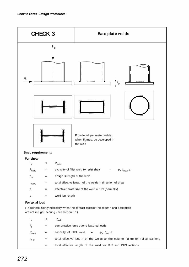
272
Column Bases - Design Procedures
Basic requirement:
For shearFv ≤ Pweld
Pweld = capacity of fillet weld to resist shear = pw lwew a
pw = design strength of the weld
lwew = total effective length of the welds in direction of shear
a = effective throat size of the weld = 0.7s (normally)
s = weld leg length
For axial load
(This check is only necessary when the contact faces of the column and base plate
are not in tight bearing - see section 8.1).
Fc ≤ Pweld
Fc = compressive force due to factored loads
Pweld = capacity of fillet weld = pw lwef a
lwef = total effective length of the welds to the column flange for rolled sections
= total effective length of the weld for RHS and CHS sections
Provide full perimeter welds
when Fc must be developed in
the weld
CHECK 3 Base plate welds
Fc
F t p
v

Column Bases - Worked Examples
Example 1: The design of a UC column base, using theeffective area method, where the columnis in direct bearing but welds must developthe shear force at the base. In this designthe effective area does not cause overlap.
Example 2: A connection similar to Example 1 butwith a higher axial load where the effectivearea calculation produces overlap and arecalculation of outstand 'c' has to bemade.
Example 3: The design of a RHS column base, usingthe effective area method, where thecolumn is in direct bearing but welds mustdevelop the shear force at the base.
Example 4: The design of a CHS column base, usingthe effective area method, where thecolumn is in direct bearing but welds mustdevelop the shear force at the base.
8.6 WORKED EXAMPLES
The four worked examples for column bases illustrate the design checks required for the most commonly used details:
273

Example 1 - Column Base - UC, no overlap SheetTitle
274
BCSA
CALCULATIONSHEET
Calcs by
Title
Client
Checked by Date
Job No Sheet
Example 1 - Column Base - UC, no overlap
SCI/BCSA Connections Group
RS AM May 2002
1 of 4
DESIGN EXAMPLE 1
Check the column base for the design forces shown.
Joints in Steel Construction - Simple Connections
100
600
600
50
F = 4300kNc
F = 100kN
305 x 305 x 137 UCGrade S355
600 x 600 x 50 Base plateGrade S275
8mm fillet welds
M24 grade 4.6holding down bolts
f = 30N/mmcu
2
Contact faces of the columnand the base plate are indirect bearing
v
Column Bases - Worked Example 1

Example 1 - Column Base - UC, no overlap SheetTitle
275
2 of 4
CAPACITY USING TABLES FROM THE YELLOW PAGES
For a 600 x 600 x 50 baseplate with C30 concrete,
Capacity given in tables = 4620kN > 4300kN ∴∴∴∴∴ O.K.
Therefore the base is adequate.
CHECK 1: Effective area method - base plate size.
Basic requirement: Ap ≥ Areq
Area of baseplate Ap = Bp Dp = 600 x 600 = 360000mm2
FcArea required, Areq = –––––– 0.6 fcu
4300 x 103= –––––––––– 0.6 x 30
= 238900mm2
Ap = 360000mm2 > 238900mm2 ∴∴∴∴∴ O.K.
Yellow pagesTable H.41
Column Bases - Worked Example 1
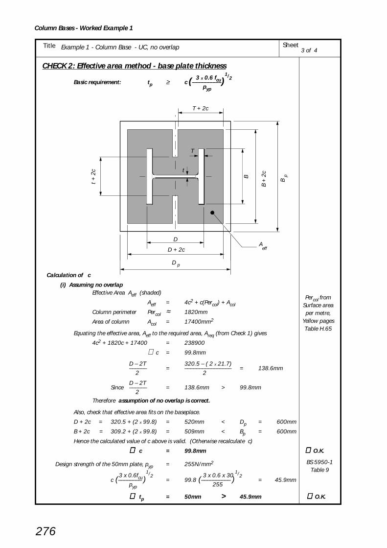
Example 1 - Column Base - UC, no overlap SheetTitle
276
CHECK 2: Effective area method - base plate thickness 3 x 0.6 fcu
1/2Basic requirement: tp ≥ c (––––––––––)
pyp
Calculation of c
(i) Assuming no overlapEffective Area Aeff (shaded)
Aeff = 4c2 + c(Percol) + Acol
Column perimeter Percol ≈ 1820mm
Area of column Acol = 17400mm2
Equating the effective area, Aeff to the required area, Areq (from Check 1) gives
4c2 + 1820c + 17400 = 238900
∴ c = 99.8mm
D – 2T 320.5 – ( 2 x 21.7)–––––– = –––––––––––––––– = 138.6mm 2 2
D – 2TSince –––––– = 138.6mm > 99.8mm
2Therefore assumption of no overlap is correct.
Also, check that effective area fits on the baseplace.
D + 2c = 320.5 + (2 x 99.8) = 520mm < Dp = 600mm
B + 2c = 309.2 + (2 x 99.8) = 509mm < Bp = 600mm
Hence the calculated value of c above is valid. (Otherwise recalculate c)
∴∴∴∴∴ c = 99.8mm ∴∴∴∴∴ O.K.
Design strength of the 50mm plate, pyp = 255N/mm2
3 x 0.6fcu 1/2 3 x 0.6 x 30
1/2c (–––––––– ) = 99.8 (–––––––––– ) = 45.9mm
pyp 255
∴∴∴∴∴ tp = 50mm > 45.9mm ∴∴∴∴∴ O.K.
3 of 4
BS 5950-1Table 9
B +
2c
BD + 2c
D
t +
2c
T
t
T + 2c
Bp
D p
Aeff
Percol fromSurface areaper metre,
Yellow pagesTable H.65
Column Bases - Worked Example 1

Example 1 - Column Base - UC, no overlap SheetTitle
277
CHECK 3 : Baseplate welds (Shear capacity of column-to-base weld )
Basic requirement: Fv ≤ Pweld
Shear capacity of fillet welds, Pweld = pw lwew a
Effective length of welds to column web, lwew (i.e. in direction of shear)
lwew = 2 (l – 2s)
= 2 (100 – (2 x 8))
= 168mm
Design strength of the weld pw
pw = 220 N/mm2
Throat size, a
a = 0.7s
= 0.7 x 8
= 5.6mm
220 x 168 x 5.6 Pweld = –––––––––––––– = 207kN
103
Fv = 100kN < 207kN ∴ ∴ ∴ ∴ ∴ O.K.
4 of 4
BS 5950-1Table 37
Column Bases - Worked Example 1

Example 1 - Column Base - UC, no overlap SheetTitle
278
BCSA
CALCULATIONSHEET
Calcs by
Title
Client
Checked by Date
Job No Sheet
Example 2 - Base Plates - UC, overlap
SCI/BCSA Connections Group
RS AM May 2002
1 of 4
DESIGN EXAMPLE 2
Check the column base for the design forces shown.
Joints in Steel Construction - Simple Connections
150
800
800
90
F = 9000kNc
F = 115kN
305 x 305 x 283 UC(Grade S355)
800 x 800 x 90 Baseplate(Grade S275)
8mm fillet welds
M36 grade 4.6holding down bolts
f = 30N/mmcu2
Contact faces of the columnand the base plate are indirect bearing
v
Column Bases - Worked Example 2

Example 1 - Column Base - UC, no overlap SheetTitle
279
CAPACITY USING TABLES FROM THE YELLOW PAGES
For a 800 x 800 x 90 baseplate with C30 concrete,
Capacity given in tables = 8370kN >| 9000kN ∴ ∴ ∴ ∴ ∴ Fails
The capacity tables indicate that the base is inadequate for the design load given.However, the table values are calculated using the smallest section within a serial size andare therefore conservative for larger weight columns. Thus, a higher capacity may beobtained if the design is carried out manually for the particular column size in question.
CHECK 1: Effective area method – base plate size.
Basic requirement, Ap ≥ Areq
Area of baseplate Ap = Bp Dp = 800 x 800 = 640000mm2
FcArea required, Areq = ––––––0.6 fcu
9000 x 103= ––––––––––
0.6 x 30
= 500000mm2
Ap = 640000mm2 > 500000mm2 ∴∴∴∴∴ O.K.
2 of 4Example 2 - Base Plates - UC, overlap
Yellow pagesTable H.41
Table H.39note (2)
Column Bases - Worked Example 2

Example 1 - Column Base - UC, no overlap SheetTitle
280
Check 2: Effective area method – baseplate thickness 3 x 0.6fcu
1/2Basic requirement: tp ≥ c ( –––––––––)
pyp
Calculation of c
(i) Assuming no overlap
Aeff = 4c2 + c(Percol) + Acol
Column perimeter Percol ≈ 1940mm
Area of column Acol = 36000mm2
Equating the effective area, Aeff to the required area, Areq (from Check 1) gives
4c2 + 1940c + 36000 = 500000
∴ c = 175.6mm
D – 2T 365.3 – ( 2 x 44.1)–––––– = –––––––––––––––– = 138.6mm 2 2
D – 2TSince –––––– = 138.6mm >| 175.6mm
2
Therefore assumption of no overlap is INCORRECT
(ii) Assuming overlap
Recalculate c on the basis of a revised effective area as shown in Figure 8.3(iii)
Aeff = (D + 2c) (B + 2c)
= 4c2 + 2(D + B)c + DB
Equating the effective area, Aeff to the required area, Areq (from Check 1) gives
4c2 + 2(365.3 + 322.2)c + 365.3 x 322.2 = 500000
∴ c = 182mm
Also check that effective area fits on the baseplate
D + 2c = 365.3 + (2 x 182) = 729.3mm < Dp = 800mm
B + 2c = 322.2 + (2 x 182) = 686.2mm < Bp = 800mm
hence the calculated value of c in (ii) above is valid.
∴∴∴∴∴ c = 182mm ∴∴∴∴∴ O.K.
Design strength of the 90mm plate
pyp = 235N/mm2
3 x 0.6fcu1/2 3 x 0.6 x 30
1/2c ( –––––––– ) = 182 ( –––––––––– ) = 87.2mm
pyp 235
tp = 90mm > 87.2mm ∴∴∴∴∴ O.K.
3 of 4
BS 5950-1Table 9
Example 2 - Base Plates - UC, overlap
See Example 1(Figure incheck 2)
Yellow pagesTable H.65
Column Bases - Worked Example 2

Example 1 - Column Base - UC, no overlap SheetTitle
281
4 of 4
CHECK 3: Baseplate welds (Shear capacity of column-to-baseplate weld)
Basic requirement: Fv ≤ Pweld
Shear capacity of fillet welds, Pweld = pw lwew a
Effective length of welds to column web, lwew (i.e. in direction of shear)
lwew = 2 (l – 2s)
= 2 (150 – (2 x 8))
= 268mm
Design strength of the weld, pw
pw = 220 N/mm2
Throat size, a
a = 0.7s
= 0.7 x 8
= 5.6mm
220 x 268 x 5.6 Pweld = –––––––––––––– = 330kN
103
Fv = 115kN < 330kN ∴ ∴ ∴ ∴ ∴ O.K.
Example 2 - Base Plates - UC, overlap
BS 5950-1Table 37
Column Bases - Worked Example 2

Example 1 - Column Base - UC, no overlap SheetTitle
282
BCSA
CALCULATIONSHEET
Calcs by
Title
Client
Checked by Date
Job No Sheet
Example 3 - Column Base - RHS
SCI/BCSA Connections Group
RS AM May 2002
1 of 4Joints in Steel Construction - Simple Connections
DESIGN EXAMPLE 3
Check the RHS column base for the design forces shown.
20
F = 900kNc
F = 100kN
200 x 100 x 10mm RHS(Grade S355)
400 x 300 x 20 Base plate(Grade S275)
M20 grade 4.6holding down bolts
f = 30N/mmcu
2
Contact faces of the columnand the base plate are indirect bearing
6mm fillet welds
300
400
100
v
Column Bases - Worked Example 3
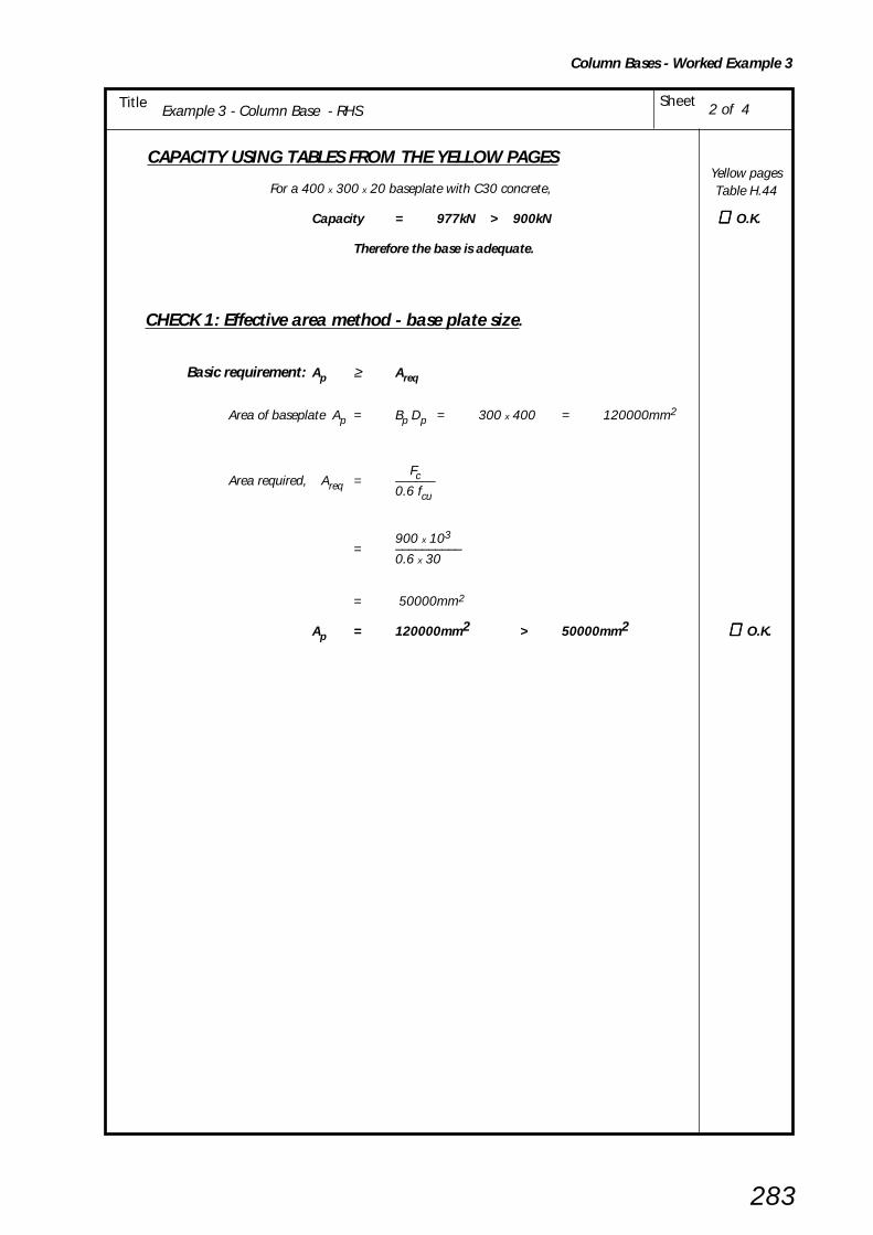
Example 1 - Column Base - UC, no overlap SheetTitle
283
2 of 4
CAPACITY USING TABLES FROM THE YELLOW PAGES
For a 400 x 300 x 20 baseplate with C30 concrete,
Capacity = 977kN > 900kN ∴ ∴ ∴ ∴ ∴ O.K.
Therefore the base is adequate.
CHECK 1: Effective area method - base plate size.
Basic requirement: Ap ≥ Areq
Area of baseplate Ap = Bp Dp = 300 x 400 = 120000mm2
FcArea required, Areq = ––––––0.6 fcu
900 x 103= ––––––––––
0.6 x 30
= 50000mm2
Ap = 120000mm2 > 50000mm2 ∴∴∴∴∴ O.K.
Example 3 - Column Base - RHS
Yellow pagesTable H.44
Column Bases - Worked Example 3

Example 1 - Column Base - UC, no overlap SheetTitle
284
CHECK 2: Effective area method - base plate thickness. 3 x 0.6fcu
1/2Basic requirement: tp ≥≥≥≥≥ c ( –––––––– )
pyp
Calculation of c
(i) Assuming no overlap
Effective Area Aeff (shaded)
Aeff = (mean perimeter of RHS) x (t + 2c)
= 2(D + B - 2t) x (t + 2c)
Equating the effective area, Aeff to the required area, Areq (from Check 1) gives
2(200 + 100 - 20) x (10 + 2c) = 50000
5600 + 1120c = 50000
∴ c = 39.6mm
B – 2t 100 – ( 2 x 10⁷)––––– = ––––––––––––– = 40mm 2 2
B – 2TSince –––––– = 40mm > 39.6mm
2Therefore assumption of no overlap is correct.
Also, check that effective area fits on the baseplate.
D + 2c = 200 + (2 x 39.6) = 279.2mm < Dp = 400mm
B + 2c = 100 + (2 x 39.6) = 179.2mm < Bp = 300mm
Hence the calculated value of c above is valid. (Otherwise recalculate c)
∴∴∴∴∴ c = 39.6mm ∴∴∴∴∴ O.K.
Design strength of the 20mm plate, pyp = 265N/mm2
3 x 0.6fcu1/2 3 x 0.6 x 30
1/2c (–––––––– ) = 39.6 (–––––––––– ) = 17.9mm
pyp 265
∴∴∴∴∴ tp = 20mm > 17.9mm ∴∴∴∴∴ O.K.
3 of 4Example 3 - Column Base - RHS
2c+t
2c+t
Outstand, c t = 10
B = 300p
Aeff
D = 400p
t = 20p
BS 5950-1Table 9
Column Bases - Worked Example 3
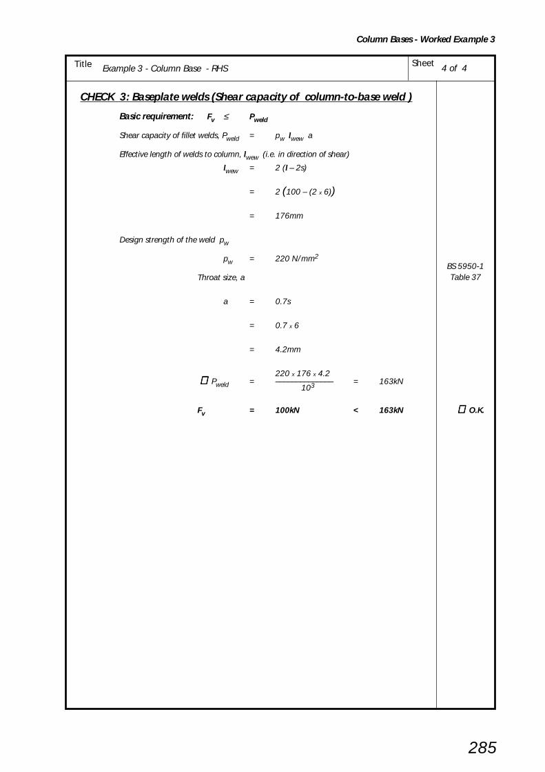
Example 1 - Column Base - UC, no overlap SheetTitle
285
CHECK 3: Baseplate welds (Shear capacity of column-to-base weld )
Basic requirement: Fv ≤ Pweld
Shear capacity of fillet welds, Pweld = pw lwew a
Effective length of welds to column, lwew (i.e. in direction of shear)
lwew = 2 (l – 2s)
= 2 (100 – (2 x 6))
= 176mm
Design strength of the weld pw
pw = 220 N/mm2
Throat size, a
a = 0.7s
= 0.7 x 6
= 4.2mm
220 x 176 x 4.2 ∴∴∴∴∴ Pweld = –––––––––––––– = 163kN
103
Fv = 100kN < 163kN ∴∴∴∴∴ O.K.
BS 5950-1Table 37
4 of 4Example 3 - Column Base - RHS
Column Bases - Worked Example 3

Example 1 - Column Base - UC, no overlap SheetTitle
286
DESIGN EXAMPLE 4
Check the CHS column base for the design forces shown.
BCSA
CALCULATIONSHEET
Calcs by
Title
Client
Checked by Date
Job No Sheet
Example 4 - Column Base - CHS
SCI/BCSA Connections Group
RS AM May 2002
1 of 4Joints in Steel Construction - Simple Connections
20
F = 1400kNc
F = 100kN
273 x 10mm CHS
400 x 400 x 20 Base plate(Grade S275)
M20 grade 4.6holding down bolts
f = 30N/mmcu
2
Contact faces of the columnand the base plate are indirect bearing
6mm fillet welds
400
400
v
Column Bases - Worked Example 4

Example 1 - Column Base - UC, no overlap SheetTitle
287
CAPACITY USING TABLES FROM THE YELLOW PAGES
For a 400 x 400 x 20 baseplate with C30 concrete,
Capacity = 1420kN > 1400kN
Therefore the base is adequate. ∴∴∴∴∴ O.K.
CHECK 1: Effective area method - base plate size.
Basic requirement: Ap ≥ Areq
Area of baseplate Ap = Bp Dp = 400 x 400 = 160000mm2
FcArea required, Areq = ––––––0.6 fcu
1400 x 103= ––––––––––
0.6 x 30
= 77778mm2
Ap
= 160000mm2
> 77778mm2
∴∴∴∴∴ O.K.
2 of 4Example 4 - Column Base - CHS
Yellow pagesTable H.42
Column Bases - Worked Example 4
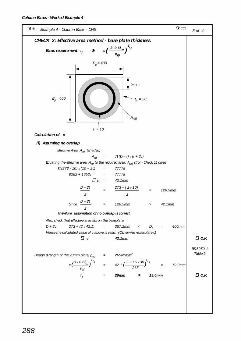
Example 1 - Column Base - UC, no overlap SheetTitle
288
3 of 44
CHECK 2: Effective area method - base plate thickness. 3 0.6fcu
1/2Basic requirement: tp ≥≥≥≥≥ c ( –––––––– )
pyp
Calculation of c
(i) Assuming no overlap
Effective Area Aeff (shaded)
Aeff = π (D – t) x (t + 2c)
Equating the effective area, Aeff to the required area, Areq (from Check 1) gives
π (273 - 10) x (10 + 2c) = 77778
8262 + 1652c = 77778
∴ c = 42.1mm
D – 2t 273 – ( 2 x 10)––––– = ––––––––––––– = 126.5mm 2 2
D – 2tSince –––––– = 126.5mm > 42.1mm
2Therefore assumption of no overlap is correct.
Also, check that effective area fits on the baseplate.
D + 2c = 273 + (2 x 42.1) = 357.2mm < Dp = 400mm
Hence the calculated value of c above is valid. (Otherwise recalculate c)
∴∴∴∴∴ c = 42.1mm ∴∴∴∴∴ O.K.
Design strength of the 20mm plate, pyp = 265N/mm2
3 x 0.6fcu 1/2 3 x 0.6 x 30
1/2c (–––––––– ) = 42.1 (–––––––––– ) = 19.0mm
pyp 265
tp = 20mm > 19.0mm ∴∴∴∴∴ O.K.
Example 4 - Column Base - CHS
t = 10
D = 400p
2c + t
A eff
t = 20pB = 400p
BS 5950-1Table 9
Column Bases - Worked Example 4
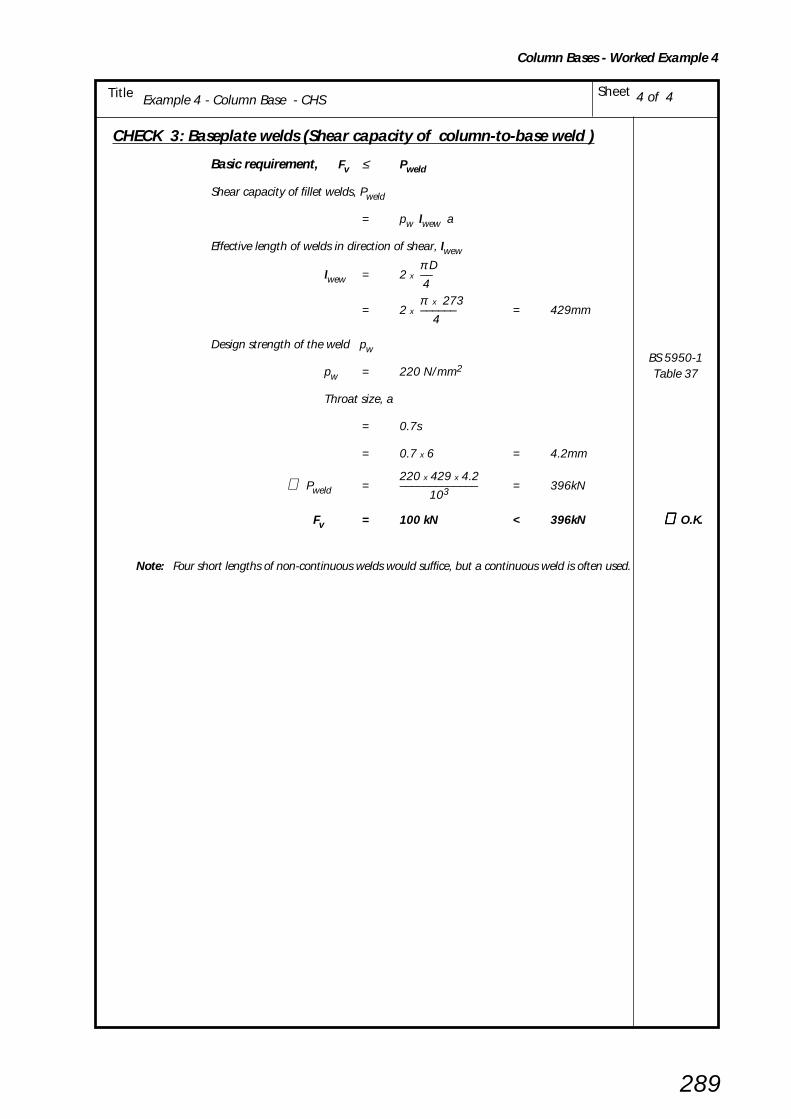
Example 1 - Column Base - UC, no overlap SheetTitle
289
CHECK 3: Baseplate welds (Shear capacity of column-to-base weld )
Basic requirement, Fv ≤ Pweld
Shear capacity of fillet welds, Pweld
= pw lwew a
Effective length of welds in direction of shear, lwew
π Dlwew = 2 x ––
4 π x 273
= 2 x –––––– = 429mm 4
Design strength of the weld pw
pw = 220 N/mm2
Throat size, a
= 0.7s
= 0.7 x 6 = 4.2mm
220 x 429 x 4.2∴ Pweld = ––––––––––––– = 396kN 103
Fv = 100 kN < 396kN ∴∴∴∴∴ O.K.
Note: Four short lengths of non-continuous welds would suffice, but a continuous weld is often used.
BS 5950-1Table 37
4 of 4Example 4 - Column Base - CHS
Column Bases - Worked Example 4
290
9. BRACING CONNECTIONS
9. 1 INTRODUCTION
This Section gives general guidance on bracingconnections and, where appropriate, refers to otherpublications for comprehensive detailed design.
Connections for bracing members comprising flats, angles,channels, I-sections, RHS and CHS are included. Gussetplates incorporating kidney shaped slots are sometimesused in bracing connections for single and multi-storeyframes; they are described in Section 9.3.
Bracing is usually designed assuming that all forces intersecton member centroids but if this assumption is carried outin the connection design then this may produce a largeconnection. It is often more convenient to arrange themember intersections to make a more compact joint andcheck locally for the effects of eccentricities.
Single angle bracing with welded gusset plates to beamsor columns and bolted site connections are simple tofabricate. CHS bracing is also economical, being effectivein both tension and compression, the connection usuallybeing made with a 'T' shaped element welded at each endof the member for site bolting to gusset plates. Fabricationcosts are generally higher for the other types of connectionsshown which have either, more elements to fabricate, ora greater weld content.
The components in the structure that attach to bracingare often the first parts to be erected since stability is thenavailable for erection of further components. Connectionsshould therefore be made such that erection can be madeswiftly and, as far as possible, without the need oftemporary supports. Care should also be taken to ensurethat there are no encumbrances built into the connectionwhich make erection difficult.
Bracing systems may include beams acting as horizontalmembers in bracing systems; the beams may be providedwith double angle cleats, flexible end plates or fin plateconnections as decribed in Sections 4, 5 or 6. It isnecessary to allow for in the connection design any axialforce present in the beams and induced shear forces, inaddition to the normal end reactions.
9. 2 DESIGN CONSIDERATIONS
Table 9.1 shows possible solutions for bracing connectionsand indicates matters relevant to each type of connection.The design method is to decide on a force path to beadopted that provides equilibrium at the joint and checkeach element for shear, tension, bearing, or buckling asappropriate.
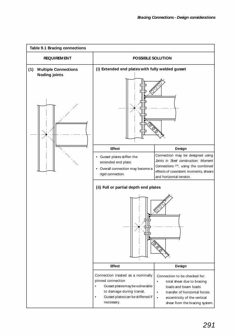
291
(1) Multiple ConnectionsNoding joints
(i) Extended end plates with fully welded gusset
Effect Design
(ii) Full or partial depth end plates
Effect Design
Connection may be designed using
Joints in Steel construction: Moment
Connections [24], using the combined
effects of coexistent moments, shears
and horizontal tension.
• Gusset plates stiffen the
extended end plate.
• Overall connection may become a
rigid connection.
Connection to be checked for:
• total shear due to bracing
loads and beam loads
• transfer of horizontal forces
• eccentricity of the vertical
shear from the bracing system.
Connection treated as a nominally
pinned connection
• Gusset plates may be vulnerable
to damage during transit.
• Gusset plates can be stiffened if
necessary.
Table 9.1 Bracing connections
REQUIREMENT POSSIBLE SOLUTION
Bracing Connections - Design considerations

292
(2) Multiple ConnectionsNon-noding joints
Effect
• Additional moments are induced
in members.
• Gusset plates may be vulnerable
to damage during transit.
Case 1
e 1
Case 2
e 2
Case 2Case 1
e 1
e 2
Individual bracing plates
Design
Check for:
• Additional moment due to
eccentricity e1 or e2.
• total shear due to bracing
components and beam loads
• horizontal forces due to bracing
Effect
• Some gusset plates that are in
compression may be prone to
buckling between the first bolt
and the connecting member.
• Single sided gusset connections
are by their nature out of
alignment
Design
• Plate buckling may be checked using
strut curve C Table 24 of BS 5950-1[1].
For further design guidance see
reference: CIMsteel Engineering
Basis [43], Cidect Guides[28] [29]
• Moments due to force eccentricity 'e'
can be ignored. Angle, channel and
T-section struts to be designed in
accordance with BS 5950-1 cl. 4.7.10
(3) Gusset Plates in compressionand axial alignment
Table 9.1 Bracing connections (continued)
REQUIREMENT POSSIBLE SOLUTION
LE
Buckling
Buckling
LE
Eccentricity
e
Eccentricity
e
Bracing Connections - Design considerations

293
(4) Bracing MembersHollow section (CHS, RHS)
Design guidance for all types of CHS and RHS connections isgiven in Cidect Guides[28] [29]
(i) Rolled or fabricated 'T'
(ii) Slotted tube
(iii) Flattened end CHS
(iv) Fork plates
(v) Castings
Stalks of standard rolled T sections arerelatively thin and therefore bolt bearingmay control capacity.
Sealing plates may be required. This typeof connection involves a relatively highamount of fabrication.
During cold flattening longitudinalcracks/splitting may apear on the edgesof the flattened CHS. Usually this has noeffect on the performance of theconnection.
Both fork plate types make more effectiveuse of bolts (double shear) but are moreexpensive to fabricate. May be requiredfor architectural reasons for single pinconnections .
Sealing plates may be required.
Castings can be economical if sufficientnumbers are required. Refer tomanufacturers.
Not used in orthodox buildings. Forfurther guidance see SCI-P172[44].
Table 9.1 Bracing connections (continued)
REQUIREMENT POSSIBLE SOLUTION
sealing plate
sealing plate
Bracing Connections - Design considerations

294
(5) Bracing MembersFlats, angles, channel, UB/UC Simple tension bracing but lacks
compression capability.
Susceptible to distortion during transport
and erection.
Double angle bracing can be ‘back-to-
back’, separated by division plates spaced
at intervals along the length (of same
thickness as the gusset) or 'starred’
formation with battens in both directions
spaced at intervals along the length.
Double channel bracing can be ‘back-to-
back', separated by division plates spaced
at intervals along the length of same
thickness as the gusset.
UB/UC The flanges on one side can be
removed to allow the gusset plate to be
bolted to the web. A web reinforcing plate
can be used if it is necessary to increase
connection capacity.
(i) Flat plate
(ii) Double Angle
(iii) Double Channel
(iv) UB/UC
Table 9.1 Bracing connections (continued)
REQUIREMENT POSSIBLE SOLUTION
Bracing Connections - Design considerations

295
9.3 KIDNEY SHAPED SLOT CONNECTIONSKidney shaped slots used in bracing connections providea practical solution for connecting members of varyinglengths and angles with standardised components. Thekidney shaped slot is generally formed in the gusset platerather than at the end of the bracing member, as shownin Figure 9.1.
Non-preloaded bolts (ordinary “bearing” bolts) are usedrather than preloaded (friction grip) bolts.
Practical ConsiderationsThe three common methods of forming the kidney shapedslot are:
• Punching full size, in one operation, using a die thatmatches the slot dimensions.
• Drilling two holes and completed by cutting.
• Machine operated plasma or flame cutting.
The advantages of a connection incorporating a kidneyshaped slot are that:
• A standard end connection can be used for bracingmembers.
• Standard gusset plates which accommodate a rangeof bracing member may be used.
• A two bolt connection allows one bolt to be insertedin the connection whilst locating and maintainingalignment with a podger spanner through the otherhole.
Standard details encourage a batch production approachto the fabrication of the connection components, andsave time in design, detailing, checking and fabrication.
Recommended GeometryThe recommended geometry for the single circular holeand the kidney shaped slot is as shown in Figure 9.2 andgiven in tables 9.2 and 9.3.
Table 9.2 Hole and slot dimensions (see Figure 9.2)
Bolt Diameter Circular Hole Kidney Shaped SlotDiameter Maximum dimensions
mm mm mm
Width Length
≤ 24 d + 2 d +2 3dsee Note 1
>24 d + 3 d +3 3dsee Note 1
Note 1: but angle θ should not exceed 30°
Table 9.3 Spacing dimensions (see Figure 9.2)
Minimum Maximum
Spacing "s” between circular hole and 2.5 d
Lesser of 14t
kidney slot:and 200 mm
End and edge distances “e” 2 d Lesser of 11tε
and 40 mm + 4t
where: 275 0.5
ε = [–––––] py
d = bolt diameter
t = thickness of gusset plate
py = design strength of gusset plate
Figure 9.1 Gusset plate with kidney shaped slot
s
s
θe
ee
hneL of slotgt
width of s
lot
Figure 9.2 Recommended geometryfor gusset plate with kidney shaped slot
Bracing Connections - Kidney shaped slot connections
296
Design RulesFor a two-bolt connection where one of the holes is kidneyshaped, the following rules are recommended,in accordance with BS 5950-1:2000:[1] clause 6.3.2.4and 6.3.3.3.
Connection CapacityTotal shear capacity = 1.6Ps
Ps = shear capacity of a single boltin standard clearance hole.
Total bearing capacity = 1.5Pbs
Pbs = bearing capacity of a gussetplate for a single bolt instandard clearance hole.
Effective Length of Bracing MemberSince the kidney shaped slot allows rotation of theconnection, the connection detail cannot be assumed toprovide directional restraint equivalent to that of two boltsin standard clearence holes.
When effective lengths for hollow section bracing membersare determined from Table 22 of BS 5950-1[1], a connectionincorporating a kidney shaped slot should not be assumedto provide any directional restraint in the plane of the gusset.
When angles are used as bracing members and theconnections incorporate kidney shaped slots, the provisionsfor single bolt connections in Table 25 of BS 5950-1[1]
should be adopted, though the reduction to 80% incompression resistance stated in Note 3 to Table 25 neednot be applied.
Provision of WashersClause 6.1.5(ii) of the National Structural SteelworkSpecification (NSSS)[8] specifies that a plate washer orheavy duty washer be used under the bolt head and nutwhen bolts are used to assemble components with oversizeor slotted holes. The origin of this clause concerned slotswhich were provided to permit movement in service.Shouldered bolts would normally be used in such joints.
The use of kidney shaped slots in bracing connections is adifferent situation to the one intended to be addressed byClause 6.1.5(ii) of the NSSS[8]. Ordinary washers areconsidered to be satisfactory for use in bracing connectionswith kidney shaped slots.
Further informationFurther information can be found in the, SCI Publication 249Design Capacity of Kidney Shaped Slotted Connections(1998)[45].
Bracing Connections - Kidney shaped slot connections
REQUIREMENT POSSIBLE SPECIALSOLUTION CONSIDERATIONS
Special Connections - Introduction
297
10. SPECIAL CONNECTIONS
10.1 INTRODUCTION
Steelwork connections for simple construction, illustratedin Sections 1 to 9 of this Guide, will generally producethe most economic steel frame. A departure from theseconnections will inevitably result in an increase in overallcost. The increase in detail drawing, fabrication anderection costs can be more than 100% if non-standardconnections form the majority of the connections used.
It is therefore good economic practice to ensure thatsteelwork can be placed with centrelines on establishedgrids. The top flanges of beams should where possiblebe at a constant level, but this is less critical to cost thaneccentric connections.
The need for special connections can often be avoidedby the judicious selection of member sizes. A minimumweight structure is unlikely to be the most cost effective.Some elegant structures employing several thousandtonnes of structural steelwork have been economicallybuilt using only six or eight sections for the whole of thedesign.
The frame design is best conducted in two stages:
1st Stage:
Obtain a satisfactory component design inaccordance with the Code of Practice.
2nd Stage:
Rationalize these components into groups toachieve a practical arrangement andreasonable range of member sizes.
Steelwork is a versatile material and a design solutioncan be found for any connection, but this may be at ahigh cost.
Quite often the solution is to use a slightly modifiedversion of one of the standardised connections, subjectto a few additional design checks. Such connectionsshould incorporate, as far as possible, the componentsizes given in Section 2 and the design principles adoptedin this Guide.
Some typical examples of situations where specialconnections are required are presented on the followingpages, together with possible configurations and anyspecial considerations affecting the design or detailing.It should be kept in mind that such connections shouldbe avoided if an alternative standard detail is possible.
Table 10.1 deals with cases where connecting beamsare at different levels. Table 10.2 considers beams whichconnect members not intersecting at 90o.
Tables 10.3 and 10.4 show connections to RHS columnswhere welding and conventional bolting are adoptedand which provide (a more expensive) alternative to theuse of Flowdrill and Hollo-Bolt connectors.
Table 10.5 takes account of eccentric connectionsnecessary for off-grid beams. Suitable connections forthese conditions must be introduced. These are oftenthe single greatest cause of the increased costs indetailing, fabrication and erection of beam/columnstructures.
A case where different size columns are spliced such thatthe outer faces are aligned is shown in Table 10.6. Thespecial requirements for a column base in a braced bayis covered in Table 10.7.

REQUIREMENT POSSIBLE SPECIALSOLUTION CONSIDERATIONS
Special Connections - Introduction
298
(1) Beam to Beam (i) If level difference is small • Reduced local shear and bendingcapacity of supported beam.
• Unrestrained top flange.
• Reduced number of bolts.
(ii) If level difference is large • To avoid the effects of torsion onthe supporting beam, design boltgroup, tees and end plates toresist moment of Fv x e.
• Expensive to fabricate.
• Pre-set to ensure alignment/levelof supported beam (especially forcantilevers).
(2) Beam to Beam (i) Increase depth of supportingmember
• Envisage ease of connection atconceptual design stage.
(ii) Notched supported beam • Reduced shear and bendingcapacity of supported beam.
• Lateral torsional buckling ofsupported beam if not laterallyrestrained.
(iii) Extended fin plate • Stability of fin plate.
• Torsional and positional restraintto supported beam.
Difference in levels
Supported beam
Supporting beam
Difference in levels
Supported beam
Supporting beam
Flexible end plate or doubleangle cleats
e
Fitted plates or structural tees
F v
Table 10.1 Beams at different levels
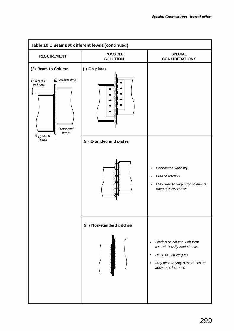
REQUIREMENT POSSIBLE SPECIALSOLUTION CONSIDERATIONS
Special Connections - Introduction
299
(3) Beam to Column (i) Fin plates
(ii) Extended end plates
• Connection flexibility.
• Ease of erection.
• May need to vary pitch to ensureadequate clearance.
(iii) Non-standard pitches
• Bearing on column web fromcentral, heavily loaded bolts.
• Different bolt lengths.
• May need to vary pitch to ensureadequate clearance.
Difference in levels
Supported beam
Supported beam
CL Column web
Table 10.1 Beams at different levels (continued)

REQUIREMENT POSSIBLE SPECIALSOLUTION CONSIDERATIONS
Special Connections - Introduction
300
(ii)Supported beam depth greaterthan supporting beam depth
End Plate
• Reduced local shear and bendingcapacity of supported beam due tolong top and bottom notch.
• Non-standard end plate may berequired.
• Weld to end plate.See BS 5950-1: 2000[1] clause 6.8.1.
(iii) Beams of same depth
Extend face of connection to toes ofsupporting beam.
• To avoid the effects of torsion on thesupporting beam, design bolt group,tees and end plates to resist momentof Fv x e.
• Expensive to fabricate.
• Clearance for bolts.
• Weld to end plate.See BS 5950-1: 2000[1] clause 6.8.1.
Table 10.2 Skewed connections
(1) Beam to Beam (i) Supported beam depth lessthan supporting beam depth
Fin Plate
• Reduced local shear and bendingcapacity of supported beam due tolong top notch.
• Non-standard fin plate may berequired due to bolt clearances.
• Weld to fin plate.See BS 5950-1: 2000[1] clause 6.8.1.
Supporting beam
Supported beam
e

REQUIREMENT POSSIBLE SPECIALSOLUTION CONSIDERATIONS
Special Connections - Introduction
301
(2) Beam to Column (i) Extended end plate
• Bolt group and end plate designedto resist moment of Fv x e.
• Weld to end plate.See BS 5950-1: 2000[1] clause 6.8.1.
• Structural integrity - large bolttensions developed.
• Structural integrity - thick end platerequired.
• Structural integrity - check columnflange for bending.
(ii)Plate across UC toes • Large shear force on one-sided filletweld to UC toe.
• Weld to end plate.See BS 5950-1: 2000[1] clause 6.8.1.
• Structural integrity - Large tensionsdeveloped in weld.
• Structural integrity - thick platesmay be required.
Beam
Column
e
Table 10.2 Skewed connections (continued)

REQUIREMENT POSSIBLE SPECIALSOLUTION CONSIDERATIONS
Special Connections - Introduction
302
(i) Channel Bracket
(ii)Tee connection
• Provides alternative to direct boltingby Flowdrill or Hollo-bolt.
• Bracket transmits load direct tocolumn side wall welds.
• Bracket and welds to resistmoment due to eccentricity.
• Tee stiffens column wall and can beused where a fin plate is insufficient.
Supportedbeam
F v
RHScolumn
(i) Side plates
(ii) Bracket
• Bolts and welds to resist Fv andany moment due to out of balanceloading.
• Bracket transmits loads direct tocolumn side wall welds.
• Bracket and welds to resistmoment due to eccentricity.
Table 10.3 I -Beam to RHS column
REQUIREMENT POSSIBLE SPECIALSOLUTION CONSIDERATIONS
e
weld details
2 to 3 mm gap
50°
2 mm nosing
50°
2 to 3 mm gap
2 mm nosing
e
Table 10.4 Parallel Beams to RHS column
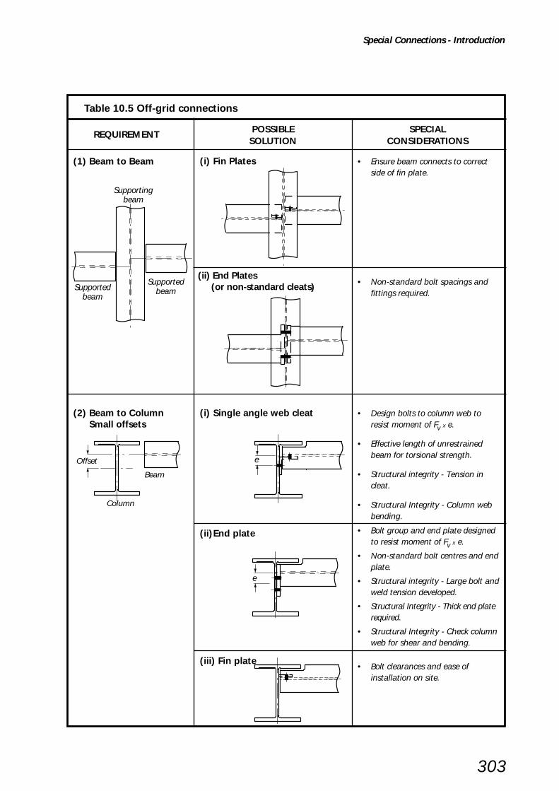
REQUIREMENT POSSIBLE SPECIALSOLUTION CONSIDERATIONS
Special Connections - Introduction
303
(1) Beam to Beam (i) Fin Plates • Ensure beam connects to correctside of fin plate.
(ii) End Plates(or non-standard cleats) • Non-standard bolt spacings and
fittings required.
(i) Single angle web cleat • Design bolts to column web toresist moment of Fv x e.
• Effective length of unrestrainedbeam for torsional strength.
• Structural integrity - Tension incleat.
• Structural Integrity - Column webbending.
(2) Beam to Column Small offsets
(ii)End plate • Bolt group and end plate designedto resist moment of Fv x e.
• Non-standard bolt centres and endplate.
• Structural integrity - Large bolt andweld tension developed.
• Structural Integrity - Thick end platerequired.
• Structural Integrity - Check columnweb for shear and bending.
(iii) Fin plate• Bolt clearances and ease of
installation on site.
Offset
Beam
Column
e
Table 10.5 Off-grid connections
Supportingbeam
SupportedbeamSupported
beam
e
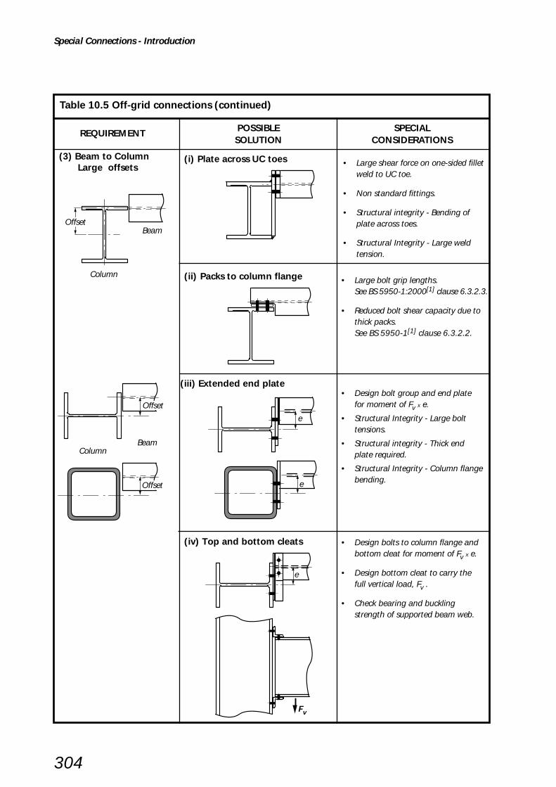
REQUIREMENT POSSIBLE SPECIALSOLUTION CONSIDERATIONS
Special Connections - Introduction
304
(i) Plate across UC toes • Large shear force on one-sided filletweld to UC toe.
• Non standard fittings.
• Structural integrity - Bending ofplate across toes.
• Structural Integrity - Large weldtension.
(3) Beam to Column Large offsets
(ii) Packs to column flange • Large bolt grip lengths.See BS 5950-1:2000[1] clause 6.3.2.3.
• Reduced bolt shear capacity due tothick packs.See BS 5950-1[1] clause 6.3.2.2.
(iii) Extended end plate• Design bolt group and end plate
for moment of Fv x e.
• Structural Integrity - Large bolttensions.
• Structural integrity - Thick endplate required.
• Structural Integrity - Column flangebending.
(iv) Top and bottom cleats • Design bolts to column flange andbottom cleat for moment of Fv x e.
• Design bottom cleat to carry thefull vertical load, Fv .
• Check bearing and bucklingstrength of supported beam web.
e
Fv
Table 10.5 Off-grid connections (continued)
Offset
Offset
ColumnBeam
Offset
Column
Beam
e
e
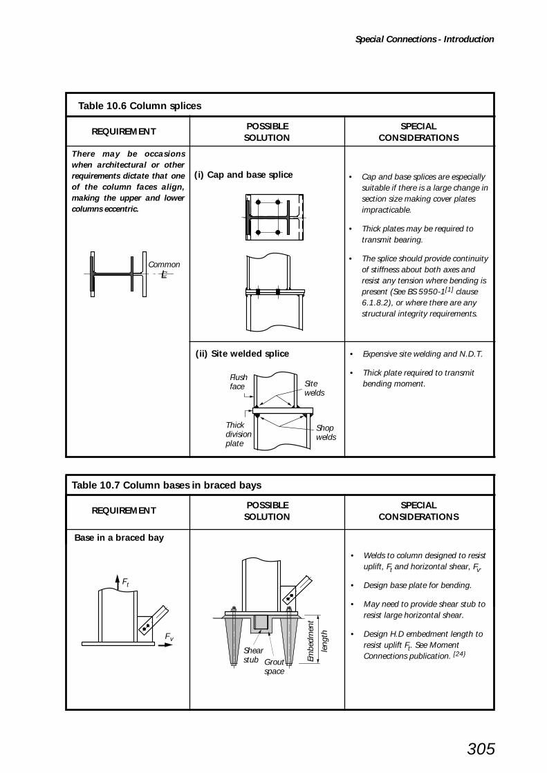
REQUIREMENT POSSIBLE SPECIALSOLUTION CONSIDERATIONS
Special Connections - Introduction
305
There may be occasionswhen architectural or otherrequirements dictate that oneof the column faces align,making the upper and lowercolumns eccentric.
(i) Cap and base splice • Cap and base splices are especiallysuitable if there is a large change insection size making cover platesimpracticable.
• Thick plates may be required totransmit bearing.
• The splice should provide continuityof stiffness about both axes andresist any tension where bending ispresent (See BS 5950-1[1] clause6.1.8.2), or where there are anystructural integrity requirements.
(ii) Site welded splice • Expensive site welding and N.D.T.
• Thick plate required to transmitbending moment.
Base in a braced bay
• Welds to column designed to resistuplift, Ft and horizontal shear, Fv.
• Design base plate for bending.
• May need to provide shear stub toresist large horizontal shear.
• Design H.D embedment length toresist uplift Ft. See MomentConnections publication. [24}
REQUIREMENT POSSIBLE SPECIALSOLUTION CONSIDERATIONS
Table 10.7 Column bases in braced bays
Table 10.6 Column splices
CommonLc
Flushface
Thickdivisionplate
Site welds
Shop welds
F
F
t
v
Shear stub Grout
space
Embe
dmen
t
leng
th

306
References
11. REFERENCES
1. BRITISH STANDARDS INSTITUTION
BS 5950: Structural use of steelwork in building.
BS 5950-1: 2000 Code of practice for design - Rolled and welded sections
BS 5950-2: 2001 Specification for materials, fabrication and erection - Rolled and welded sections
2. BRITISH STANDARDS INSTITUTION
BS4 Structural steel sections
BS4-1: 1993 Specification for hot rolled sections
(Including amendment 2001)
3. BRITISH STANDARDS INSTITUTION
BS EN 10210 Hot finished structural hollow sections of non-alloy and fine grain structural
steels
BS EN 10210-1: 1994 Technical delivery requirements
BS EN 10210-2: 1997 Tolerances and sectional properties. (Replaces BS 4848: 1991)
4. BRITISH STANDARDS INSTITUTION
BS EN 10219 Cold formed welded structural sections of non-alloy and fine grain steels
BS EN 10219-1: 1997 Technical delivery requirements
BS EN 10219-2: 1997 Tolerances and sectional properties. (Replaces BS 6363: 1983)
5. JARRETT, N.D.
Axial tests on beam/column connections
BRE Client Report CR 55/90
Building Research Establishment 1990.
6. M.R. WILLFORD and A.C. ALLSOP
Design Guide for Wind Loads on Unclad Frames
Building Structures During Construction, (Report BR173)
Building Research Establishment 1990.
7. Joints in Steel Construction - Composite Connections (SCI-P213)
The Steel Construction Institute and
The British Constructional Steelwork Association Ltd, 1998
8. NATIONAL STRUCTURAL STEELWORK SPECIFICATION FOR BUILDING CONSTRUCTION
4th Edition. - BCSA & SCI Publication No. 203/02
British Constructural Steelwork Association Ltd & The Steel Construction Institute, 2002
9. CIMsteel
Design for Manufacture Guidelines (SCI-P150)
The Steel Construction Institute, 1995
10. BRITISH STANDARDS INSTITUTION
BS 4190: 2001 ISO metric black hexagon bolts, screws and nuts - Specification
11. BRITISH STANDARDS INSTITUTION
BS 4395 Specification for high strength friction grip bolts and associated nuts and washers for
structural engineering
BS 4395-1: 1969 General grade (including amendments 1, amendments 2: 1997)
BS 4395-2: 1969 Higher grade bolts and nuts and general grade washers (including
amendment 1, amendment 2: 1976)

307
References
12. OWENS, G.W.
Use of fully threaded bolts for connections in structural steelwork for buildings
Journal of the Institute of Structural Engineers 1st September 1992 pp297 - 300
13. BRITISH STANDARDS INSTITUTION
BS EN 1011 Welding - Recommendations for welding of metalic materials
BS EN 1011-1: 1998 General guidance for arc welding
BS EN 1011-2: 2001 Arc welding of ferritic steels
14. CHENG, J.J.R.and URA, J.A.
Local web buckling of coped beams
Journal of the Structural Division, ASCE, October 1986.
15. CHENG, J.J.R., YURA, J.A. and C.P. JOHNSON
Design and Behaviour of Coped Beams
PMFSEL Report No. 841, July 1984
Department of Civil Engineering, University of Texas at Austin
16. JARRETT, N.D.
Tests on beam/column web side plate connections
BRE Client Report CR 54/90
Building Research Establishment, Watford, September 1990.
17. HOGAN, T.J. and D THOMAS, I.R.
Design of structural connections 3rd edition
Australian Institute of Steel Construction, Milsons Point, 1988.
18. CHENG, J.J.R. and YURA, J.A.
Lateral buckling tests on coped steel beams
Journal of the Structural Division, ASCE, January 1988.
19. GUPTA, A.K.
Buckling of coped steel beams
Journal of the Structural Division, ASCE, September 1984.
20. CHENG, J.J.R., YURA, J.A. and JOHNSON, C.P.
Lateral buckling of coped steel beams
Journal of the Structural Division, ASCE, January 1988.
21. BRITISH STANDARDS INSTITUTION
BS EN 10025: 1993 Hot rolled products of non-alloy structural steels. Technical delivery
conditions (including amendment 1995)
22. GENT, A.R. and MILNER, H.R.
The ultimate load capacity of elastically restrained H-columns under biaxial bending
Proceedings of the Institute of Civil Engineers, London, December 1968
23. GIBBONS, C., NETHERCOT, D.A., KIRBY, P.A. and WANG, Y.C.
An appraisal of partially restrained column behaviour in non-sway steel frames
Preceedings of the Institute of Civil Engineers, Structures and Buildings, 1993. Volume 99, Feb
24. Joints in Steel Construction: Moment Connections (SCI-P207/95)
The Steel Construction Institute and
The British Constructional Steelwork Association Ltd. 1995
25. JARRETT, N.D.
An experimental investigation of the behaviour of fin plate connections to deep beams
Building Research Establishment, Watford, February 1994

308
References
26. Design of the Web-Side-Plate Steel Connection Design Booklet 5.1
BHP Structural Steel
Composite Structures Design Manual, December 1999
27. An Improved Method for Designing the Web-Side-Plate Steel Connection
(Supplement to DB 5.1)
BHP Structural Steel, December 1999
28. WARDENIER, J., KUROBANE, Y., PACKER, J.A., DUTTA, D. and YEOMANS, N.
Design Guide for Circular Hollow Section (CHS) Joints under predominently Static Loading
CIDECT, 1991
29. PACKER, J.A., WARDENIER, J., KUROBANE, Y., DUTTA, D. and YEOMANS, N.
Design Guide for Rectangular Hollow Section (RHS) Joints under predominently Static Loading
CIDECT, 1992
30. Safe Erection of Structures
Guidance Notes GS 28/1 to 4
Health and Safety Executive, 1986
31. BRITISH STANDARDS INSTITUTION
BS 4604 Specification for the use of high strength friction grip bolts in structural steelwork.
Metric series
BS 4604-1: 1970 General grade (including amendment 1, amendment 2 and amendment 3: 1982)
BS 4604-2: 1970 Higher grade (parallel shank) (including amendment 1, amendment 2: 1972)
32. YURA, J.A., HANSEN, M.A. and FRANK, K.H.
Bolted splice connections with undeveloped fillers
Journal of the Structural Division, ASCE, December 1982
33. "Slip Factors of Connections with HSFG Bolts"
ECCS Publication No. 37
European Convention for Constructional Steelwork, 1984
34. Holding down systems for steel stanchions
The Concrete Society, The British Constructional Steelwork Association Limited and
The Steel Construction Institute, Ascot, October 1980
35. BRITISH STANDARDS INSTITUTION
BS 7419: 1991 Specification for Holding down bolts
36. BRITISH STANDARDS INSTITUTION
BS 7371-3: 1993 Coatings on metal fasteners. Specification for electroplated zinc and cadmium coatings.
37. BRITISH STANDARDS INSTITUTION
BS 7371-6: 1988 Coatings on metal fasteners. Specification for hot dipped galvanized coatings.
38. BRITISH STANDARDS INSTITUTION
BS 7371-6: 1998 Coatings on metal fasteners. Specification for sherardized coatings.
39. BRITISH STANDARDS INSTITUTION
BS EN 499: 1995 Welding consumables. Covered electrodes for manuak metal arc welding
of non-alloy and fine grain. Classification
40. BRITISH STANDARDS INSTITUTION
BS 4320: 1968 Specifications for metal washers for general engineering purposes. Metric series
41. BRITISH STANDARDS INSTITUTION
BS 5531: 1988 Code of practice for safety in erecting structural frames

309
References
42. BRITISH STANDARDS INSTITUTION
BS 5328-1: 1997 Concrete. Guide to specifying concrete
43. CIMsteel
Connection design and detailing (Engineering basis documents) (SCI-P151)
The Steel Construction Institute, 1995
44. BADDOO, N.R.
Castings in construction (SCI-P172)
The Steel Construction Institute, 1996.
45. BROWN, D.G. and TIZANI, W.
Technical report: Design capacity of kidney shaped slotted connections (SCI-P249)
The Steel Construction Institute, 1998.
46. The Building Regulations Approved Document A - Structure, 1991
(as amended 2000)
Department for Transport, Local Government and the Regions
The Stationery Office, 2000.
47. VAN DALEN, K. and MACINTYRE, J.
The rotational behavoiur of clipped end plate connections
Canadian Journal of Civil Engineering, Volume 15, 1988.
48. BRITISH STANDARDS INSTITUTION
BS EN 440: 1995 Welding consumables. Wire electrodes and deposits for gas shielded metal
arc welding of non-alloy and fine grain steels. Classification
49. BRITISH STANDARDS INSTITUTION
BS EN 756: 1996 Welding consumables. Wire electrodes and wire-flux combinations for
submerged arc welding of non-alloy and fine grain steels. Classification
50. BRITISH STANDARDS INSTITUTION
BS EN 758: 1997 Welding consumables. Tubular cored electrodes for metal arc welding
with and without a gas shield of non-alloy and fine grain steels. Classification
51. BRITISH STANDARDS INSTITUTION
BS EN 1668: 1997 Welding consumables. Rods, wires and deposits for tungsten inert gas
welding of non-alloy and fine grain steels. Classification
52. BRITISH STANDARDS INSTITUTION
BS EN 4933: 1973 Specification for ISO metric black cup and countersunk head bolts and
screws with hexagon nuts

310
Bibliography
12. BIBLIOGRAPHY
ANDERSON, D., READINGS, S.J. and KAVIANPOUR, K.Wind-moment design for unbraced frames (SCI-P082)The Steel Construction Institute, 1991
BEUFOY, L.A. and MOHARRAM, A.Derived moment-angle curves for web-cleat connectionsPreliminary Publication, Third Congress IABSE Leige, 1948.
BIRKEMOE, P.C. and GILMOR, M.I.Behaviour of bearing critical double-angle beam connectionsEngineering Journal, AISC, 1978.
BRITISH STANDARDS INSTITUTIONBS EN ISO 4014:2001 Hexagon head bolts. Product grades A and B
BRITISH STANDARDS INSTITUTIONBS EN ISO 4016:2001 Hexagon head bolts. Product grade C
BRITISH STANDARDS INSTITUTIONBS EN ISO 4017:2001 Hexagon head screws. Product grades A and B
BRITISH STANDARDS INSTITUTIONBS EN ISO 4018:2001 Hexagon head screws. Product grade C
BRITISH STANDARDS INSTITUTIONBS EN ISO 4032:2001 Hexagon nuts, style 1. Product grades A and B
BRITISH STANDARDS INSTITUTIONBS EN ISO 4034:2001 Hexagon nuts. Product grade C
BRITISH STANDARDS INSTITUTIONBS EN ISO 7091:2000 Plain washers. Normal series. Product grade C
COUCHMAN, G.H.Design of semi-continuous braced frames (SCI-P183)The Steel Contruction Institute, 1997.
Engineering for steel construction, source book on connectionsAmerican Institute of Steel Construction, 1984.
GARASMI, S., WAKIYAMA, K., MATSUMOTO, T. and MURASE, Y.Limit design of high strength bolted tube flange joint, part 1 and 2.Journal of Structural & Construction Engineering Transactions of AIJ, Department of ArchitectureReports, Osaka University, Japan, August 1985.
GIRHAMMAR, U.A.Ultimate capacity of beam-column connections in damaged steel. Steel structures, advances, designand constructionProceedings of the International Conference on Steel and Aluminium Structures, Cardiff 1987.
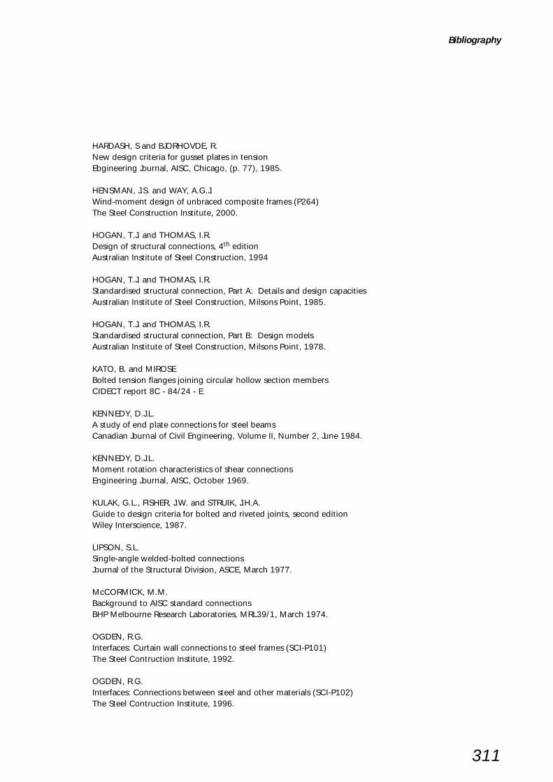
311
Bibliography
HARDASH, S and BJORHOVDE, R.New design criteria for gusset plates in tensionEbgineering Journal, AISC, Chicago, (p. 77), 1985.
HENSMAN, J.S. and WAY, A.G.J.Wind-moment design of unbraced composite frames (P264)The Steel Construction Institute, 2000.
HOGAN, T.J. and THOMAS, I.R.Design of structural connections, 4th editionAustralian Institute of Steel Construction, 1994
HOGAN, T.J. and THOMAS, I.R.Standardised structural connection, Part A: Details and design capacitiesAustralian Institute of Steel Construction, Milsons Point, 1985.
HOGAN, T.J. and THOMAS, I.R.Standardised structural connection, Part B: Design modelsAustralian Institute of Steel Construction, Milsons Point, 1978.
KATO, B. and MIROSEBolted tension flanges joining circular hollow section membersCIDECT report 8C - 84/24 - E
KENNEDY, D.J.L.A study of end plate connections for steel beamsCanadian Journal of Civil Engineering, Volume II, Number 2, June 1984.
KENNEDY, D.J.L.Moment rotation characteristics of shear connectionsEngineering Journal, AISC, October 1969.
KULAK, G.L., FISHER, J.W. and STRUIK, J.H.A.Guide to design criteria for bolted and riveted joints, second editionWiley Interscience, 1987.
LIPSON, S.L.Single-angle welded-bolted connectionsJournal of the Structural Division, ASCE, March 1977.
McCORMICK, M.M.Background to AISC standard connectionsBHP Melbourne Research Laboratories, MRL39/1, March 1974.
OGDEN, R.G.Interfaces: Curtain wall connections to steel frames (SCI-P101)The Steel Contruction Institute, 1992.
OGDEN, R.G.Interfaces: Connections between steel and other materials (SCI-P102)The Steel Contruction Institute, 1996.

312
Bibliography
OWENS, G.W. and CHEAL, B.D.Structural steelwork connectionsButterworths, London, 1989.
PACKER, J.A. and HENDERSON, J.E.Hollow structural section connections and trusses - a design guide, second editionCanadian Institute of Steel Construction, 1997.
PATRICK, M., THOMAS, I.R. and BENNETTS, I.D.Testing of the web side plate connectionAustralian Welding Research, December 1986.
Recommendations for the design and fabrication of tubular structures in steel, 3rd EditionArchitectural Institute of Japan, 1990.
RICHARD, R.M., GILLETT, P.E., KRIEGH, J.D. and LEWIS, B.A.The analysis and design of single plate framing connectionsEngineering Journal, AISC, Volume 17, No. 2, 1980.
RICHARD, R.M., KRIEGH, J.D. and HORMBY, D.E.Design of single plate framing connections with A307 boltsEngineering Journal, AISC, 1982.
RICLES, J.M. and YURA, J.A.Strength of double-row bolted web connectionsJournal of the Structural Division, ASCE, January 1983.
SALTER, P.R., COUCHMAN, G.H. and ANDERSON, D.Wind-moment design of low rise frames (SCI - P263)The Steel Construction Institute, 2000.
THE STEEL CONSTRUCTION INSTITUTE, and THE BRITISH CONSTRUCTIONAL STEELWORKASSOCIATION LTDJoints in simple constructionVolume 1: Design methods (2nd. Edition). 1993volume 2: Practical applications, 1992SCI, BCSA
Steel framed Commercial Buildings 1990-2000PETER BRETT ASSOCIATES(Private Report to British Steel and BCSA)
SYAM, A.A. and CHAPMAN, B.G.Design of structural steel hollow section connections, first edition, Volume 1: Design ModelsAustralian Institute of Steel Construction, 1996.
YOUNG, N.W. and DISQUE, R.O.Design aids for single plate framing connectionsEngineering Journal, AISC, Volume 18, No. 4, 1981.

313
APPENDICES
Appendix A STRUCTURAL INTEGRITY 314
Appendix B LARGE DISPLACEMENT ANALYSIS - DOUBLE ANGLE WEB CLEATS 317
Appendix C LARGE DISPLACEMENT ANALYSIS - FLEXIBLE END PLATES 322
Appendix D DESIGN FOR PRYING WHEN RESISTING TYING FORCES 325
Appendix E BASE PLATE DESIGN (BS 5950:Part1:1990 method) 327
Appendix F THERMAL DRILLING OF RHS 329
Appendix G HOLLO-BOLT JOINTING OF RHS 331
Appendix H CAPACITY TABLES, DIMENSIONS FOR DETAILING AND GENERAL DATA 333(YELLOW PAGES)

314
A.1 GENERAL
BS 5950-1:2000[1] clause 2.4.5 deals with structuralintegrity and the avoidance of disproportionate collapse.Compliance with this code is deemed to satisfy the BuildingRegulations Approved Document A[46].
The structural integrity requirements need to be satisfiedfor beam to column connections and for column splices.Design methods are given in Sections 4 to 7 for each of theconnection types within these headings. It has beenassumed that beam to beam connections are very rarelyrequired to meet the structural integrity clauses, and thusno design methods are offered. (Designers may adapt thebeam to column design methodology in situations wherebeam to beam connections are required to meet structuralintegrity requirements.)
There has also been a lack of data on the ultimate strengthof connections making it difficult to relate BS 5950-1[1] toultimate capacity with a high level of confidence. A testprogramme[5] completed in June 1990 determined theultimate capacities for a range of connections covered inthis design guide.
Appendices B, C, and D give a summary of the results ofthe test programme, and set out complete analyticalmodels. In some cases, simplified versions of these modelsare presented in the design methods for each type ofconnection. The simplified models give conservative values.
Although BS 5950-1[1] only relates to design of thesteelwork, the structural integrity requirements areintended to ensure robustness of the completed structure.Other structural elements may also be used to satisfy thetying force requirements. For example, with compositefloor systems, it is possible to design and detail thereinforcement, the concrete slab, and the shear connectorsto comply with BS 5950-1[1]. This will usually givesimpler design procedures and greater economy thancarrying the tying force through the connections.
The following subsections examine the resistance, underlarge displacements, of double angle web cleats, endplates and fin plates. Critical cases are identified which arelikely to be the weakest connections to be used in practice.
APPENDIX A STRUCTURAL INTEGRITY
A.2 DOUBLE ANGLE WEB CLEATS
Eleven cleats were tested to destruction to verify apostulated design procedure for the ultimate capacity ofsuch connections. Two specimens comprised the smallestcleats likely to be used in practice and which wouldsatisfy BS 5950-1[1] edge distance and other detailingrequirements, see Figure A.1; these failed at 178 and 210 kN.
Angle cleats: 2 no. 100 x 100 x 8 Grade S275 steel
Bolts: 4 no. M20 8.8in clearance holes
Critical case is:Maximum gauge, g = 140mmMinimum beam web thickness, tw = 6mmMinimum cleat thickness, tC = 6mmMinimum cleat length, l = 140mm
Figure A.1 Minimum practical double angle web cleat connection
Appendix B gives a complete design method fordetermining the ultimate capacity. The design checks inSection 4 give a simplified design method. These two designmethods are compared to the test results in Figure A.2.
BS 5950-1[1] clause 2.4.5.2 requires a minimum tie forceof 75 kN. The coefficients of regression listed in Figure A.2show that the ultimate capacities of the smallest cleatsare not isolated results, but are part of a family of results.
33
1
40
3
3
6363
51
55 45
6
35
70
35
140
336733 67
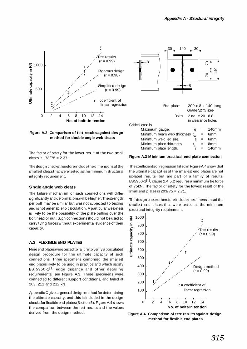
315
The factor of safety for the lower result of the two smallcleats is 178/75 = 2.37.
The design checks therefore include the dimensions of thesmallest cleats that were tested as the minimum structuralintegrity requirement.
Single angle web cleatsThe failure mechanism of such connections will differsignificantly and deformations will be higher. The strengthper bolt may be similar but was not subjected to testingand is not amenable to calculation. A particular weaknessis likely to be the possibility of the plate pulling over thebolt head or nut. Such connections should not be used tocarry tying forces without experimental evidence of theircapacity.
A.3 FLEXIBLE END PLATES
Nine end plates were tested to failure to verify a postulateddesign procedure for the ultimate capacity of suchconnections. Three specimens comprised the smallestend plates likely to be used in practice and which satisfyBS 5950-1[1] edge distance and other detailingrequirements, see Figure A.3. These specimens wereconnected to different support conditions, and failed at203, 211 and 212 kN.
Appendix C gives a general design method for determiningthe ultimate capacity, and this is included in the designchecks for flexible end plates (Section 5). Figure A.4 showsthe comparison between the test results and the valuesderived from the design method.
Appendix A - Structural integrity
Figure A.2 Comparison of test results against design method for double angle web cleats
Figure A.4 Comparison of test results against design method for flexible end plates
0 2 4 6 8 10 12 14No. of bolts in tension
500
1000
Ult
imat
e ca
pac
ity
in K
N
Test results (r = 0.99)
Rigorous design (r = 0.98)
Simplified design (r = 0.99)
r = coefficient of linear regression
30 140 30
6
140
70
7
08
r = coefficient of linear regression
0 2 4 6 8 10 12 14No. of bolts in tension
100
Ult
imat
e ca
pac
ity
in K
N
200
300
400
500
600
700
800
900
1000
Test results (r = 0.99)
Design method (r = 0.99)
End plate: 200 x 8 x 140 long Grade S275 steel
Bolts: 2 no. M20 8.8in clearance holes
Critical case is:Maximum gauge, g = 140mmMinimum beam web thickness, tw = 6mmMinimum weld leg size, s = 6mmMinimum plate thickness, tp = 8mmMinimum plate length, l = 140mm
Figure A.3 Minimum practical end plate connection
The coefficients of regression listed in Figure A.4 show thatthe ultimate capacities of the smallest end plates are notisolated results, but are part of a family of results.BS 5950-1[1], clause 2.4.5.2 requires a minimum tie forceof 75kN. The factor of safety for the lowest result of thesmall end plates is 203/75 = 2.71.
The design checks therefore include the dimensions of thesmallest end plates that were tested as the minimumstructural integrity requirement.

316
A.4 FIN PLATES
The ultimate capacity of fin plates can be determined bysimple structural analysis; the structural model is notcomplex. The design checks include the details of theminimum fin plate required to resist 75 kN tie force(BS 5950-1[1], clause 2.4.5.2). Checks are also given forresisting higher tie forces.
A.5 PRYING AND TIE FORCES
BS 5950-1[1], clause 2.4.5.1 accepts substantial permanentdeformations of members and their connections. Severalunusual features follow from taking account of the benefitsof large displacements and strains:
i) The gross deformations can reduce the localeccentricities within the connection.
ii) The local strains are so high that account can be taken of strain hardening, so that the design strength isbased on Us the minimum ultimate tensile strength,with a suitable value γm.
iii) Prying forces and bolt strains are so high that it is notappropriate to rely on nominal tension strength (0.8pt)of the bolts (see BS 5950-1[1] clause 6.3.4.2).
iv) Plate bearing strengths for ordinary bolts are setrelatively low in BS 5950-1[1] table 32 in order toensure that bearing deformations at working loads willnot lead to any unserviceability. For high strengthfriction grip bolts the bearing strengths (clause 6.4.4)are significantly higher since joint serviceability isprovided by the frictional resistance, so it is appropriateto use these higher values when designing to resisttying forces.
A reduced bolt design strength is derived in Appendix Dwhich takes prying forces into account when resistingtying forces.
Appendix A - Structural integrity

317
iii) There are four critical sections in each cleat, which aresubject to high plastic strains under the combinedaction of shear, tension and moment. Two are locatedat, or near, the bolt centrelines; two are located at thetips of the radiused portion of the heel of the cleat.(The heel itself is subject to higher moments but isreinforced by the radius.)
LARGE DISPLACEMENT ANALYSIS BASED ONULTIMATE LOAD TESTS
B.1 BehaviourFigure B.1 shows the deformed shape of a double anglecleat connection that has been subjected to high tension.The noteworthy features are:
i) The potential magnitude of the displacement ∆;ignoring second order effects, ∆ defines the displacedgeometry of the web cleats. (In the tests, the valuesof ∆ always exceeded 30mm prior to failure.)
ii) These displacements reduce the eccentricities on theweb cleats. Part of the tying force is carried bytension in the legs of the cleats. (There are also shearsassociated with the moments.)
APPENDIX B LARGE DISPLACEMENT ANALYSIS
DOUBLE ANGLE WEB CLEATS
Figure B.1 Double angle web cleats under tension
Eccentricity
Tie force
Critical sections
∆
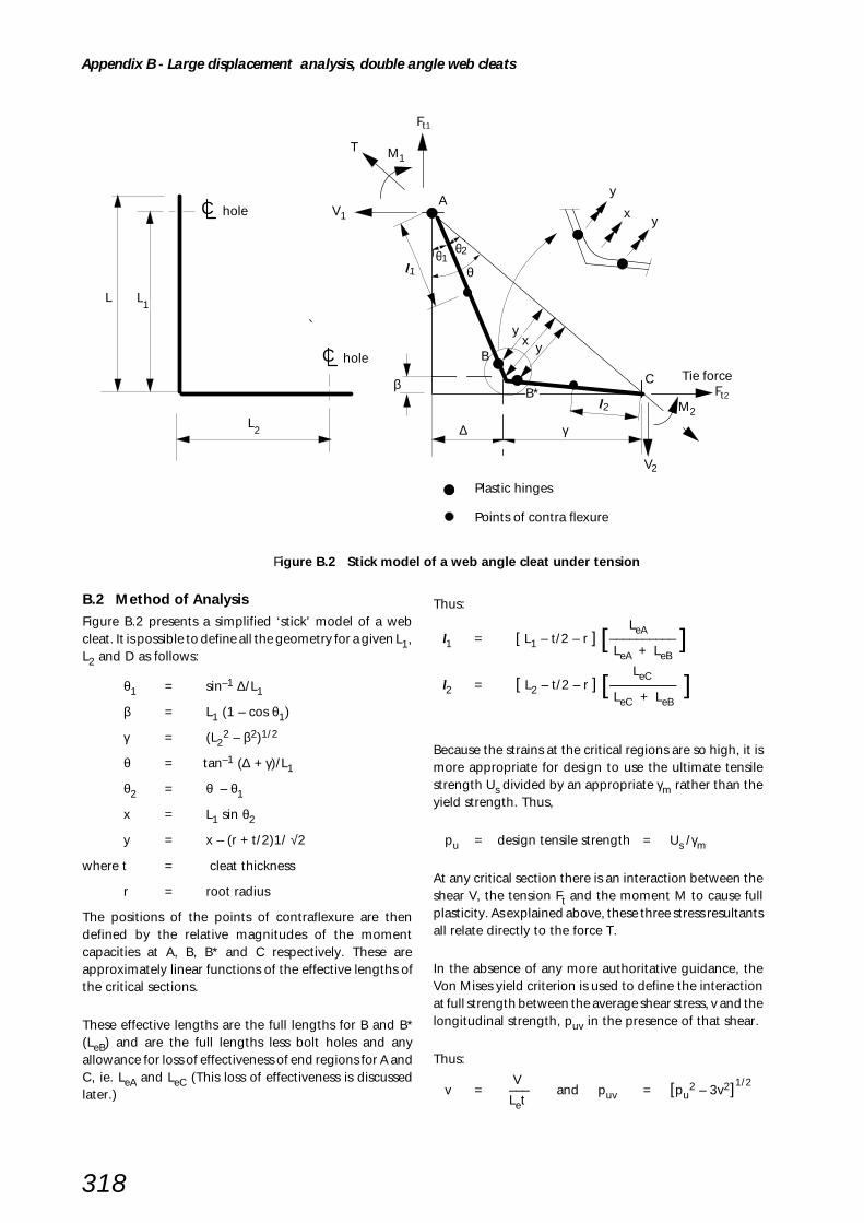
318
θ
θθ1
C
C
hole
hole
L L1
L2
y
xy
B
B*C
M2
Ft2
V2
Tie force
l2
∆ γ
β
yx y
A
M1
Ft1
l1
T
V1
2
Plastic hinges
Points of contra flexure
Figure B.2 Stick model of a web angle cleat under tension
B.2 Method of AnalysisFigure B.2 presents a simplified ‘stick’ model of a webcleat. It is possible to define all the geometry for a given L1,L2 and D as follows:
θ1 = sin–1 ∆/L1
β = L1 (1 – cos θ1)
γ = (L22 – β2)1/2
θ = tan–1 (∆ + γ)/L1
θ2 = θ – θ1
x = L1 sin θ2
y = x – (r + t/2)1/ √2
where t = cleat thickness
r = root radius
The positions of the points of contraflexure are thendefined by the relative magnitudes of the momentcapacities at A, B, B* and C respectively. These areapproximately linear functions of the effective lengths ofthe critical sections.
These effective lengths are the full lengths for B and B*(LeB) and are the full lengths less bolt holes and anyallowance for loss of effectiveness of end regions for A andC, ie. LeA and LeC (This loss of effectiveness is discussedlater.)
Thus:
LeA l1 = [ L1 – t/2 – r ] [–––––––––– ]
LeA + LeB
LeC l2 = [ L2 – t/2 – r ] [–––––––––– ]
LeC + LeB
Because the strains at the critical regions are so high, it ismore appropriate for design to use the ultimate tensilestrength Us divided by an appropriate γm rather than theyield strength. Thus,
pu = design tensile strength = Us /γm
At any critical section there is an interaction between theshear V, the tension Ft and the moment M to cause fullplasticity. As explained above, these three stress resultantsall relate directly to the force T.
In the absence of any more authoritative guidance, theVon Mises yield criterion is used to define the interactionat full strength between the average shear stress, v and thelongitudinal strength, puv in the presence of that shear.
Thus:
V v = ––– and puv = [pu
2 – 3v2]1/2
Let
Appendix B - Large displacement analysis, double angle web cleats
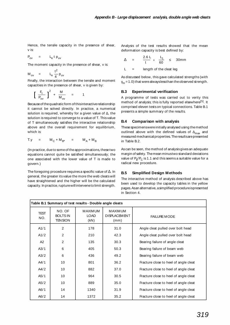
319
Analysis of the test results showed that the meandeformation capacity is best defined by:
2.6 L L1 ∆ = –––– x ––– ≤ 30mm t 60
L = length of the cleat leg
As discussed below, this gave calculated strengths (withγm = 1.0) that were always less than the observed strength.
B.3 Experimental verificationA programme of tests was carried out to verity thismethod of analysis; this is fully reported elsewhere[5]. Itcomprised eleven tests on typical connections. Table B.1presents a simple summary of the results.
B.4 Comparison with analysisThese specimens were initially analysed using the methodoutlined above with the defined values of ∆max andmeasured mechanical properties. The results are presentedin Table B.2.
As can be seen, the method of analysis gives an adequatemargin of safety. The mean minus two standard deviationsvalue of PE/PC is 1.1 and this seems a suitable value for aradical new procedure.
B.5 Simplified Design MethodsThe interactive method of analysis described above hasbeen used to develop the capacity tables in the yellowpages. As an alternative, a simplified procedure is presentedin Section 4.
Hence, the tensile capacity in the presence of shear,v is:
Pov = Le t puv
The moment capacity in the presence of shear, v is:
t2Mov = Le –– puv 4Finally, the interaction between the tensile and momentcapacities in the presence of shear, v is given by:
Ft 2 M
[ –––– ] + –––– = 1 Pov Mov
Because of the quadratic form of this interactive relationshipit cannot be solved directly. In practice, a numericalsolution is required, whereby for a given value of ∆, thesolution is required to converge to a value of T. This valueof T simultaneously satisfies the interactive relationshipabove and the overall requirement for equilibrium,which is:
T.y = MC + MB* = MA + MB
(In practice, due to some of the approximations, these twoequations cannot quite be satisfied simultaneously; theone associated with the lower value of T is made togovern.)
The foregoing procedure requires a specific value of ∆. Ingeneral, the greater its value the more the web cleats willhave straightened and the higher will be the calculatedcapacity. In practice, rupture will intervene to limit strength.
Table B.1 Summary of test results - Double angle cleats
TESTNO. OF MAXIMUM MAXIMUM
FAILURE MODENO.BOLTS IN LOAD DISPLACEMENTTENSION (kN) (mm)
A1/1 2 178 31.0 Angle cleat pulled over bolt head
A1/2 2 210 42.3 Angle cleat pulled over bolt head
A2 2 135 30.3 Bearing failure of angle cleat
A3/1 6 405 50.3 Bearing failure of beam web
A3/2 6 436 49.2 Bearing failure of beam web
A4/1 10 801 36.2 Fracture close to heel of angle cleat
A4/2 10 882 37.0 Fracture close to heel of angle cleat
A5/1 10 964 30.5 Fracture close to heel of angle cleat
A5/2 10 889 35.0 Fracture close to heel of angle cleat
A6/1 14 1340 31.9 Fracture close to heel of angle cleat
A6/2 14 1372 35.2 Fracture close to heel of angle cleat
Appendix B - Large displacement analysis, double angle web cleats

320
Table B.2 Comparison between experimental results and design model
TEST MAXIMUM LOAD CALC. CAPACITYPE/PCNO. PE (kN) PC (kN)
A1/1 178 123 1.45
A1/2 210 125 1.68
A2/1 135 93 1.45
A3/1 405 331 1.22
A3/2 436 325 1.34
A4/1 801 553 1.45
A4/2 882 550 1.60
A5/1 964 744 1.30
A5/2 889 728 1.22
A6/1 1340 1047 1.28
A6/2 1372 1059 1.30
Mean PE/PC = 1.39
Standard deviation PE/PC = 0.151
In the limit the cleats would pull out straight and all thetying forces would be carried by membrane action. Ittherefore seems appropriate to base this simple approachon the net section of the cleats in tension. A parametricstudy showed that a capacity of 0.6 x the yield capacity ofthe net section was always less than the design capacity(with γm = 1.25) determined by the large displacementanalysis above. This study covered all the specimenstested, together with representative standard connections.The results are summarised in Table B.3 in which thecalculations for the test specimens are based on measuredgeometry and properties; those for the standardconnections marked with an * are based on nominalgeometry and design strengths.
Because the simple tension capacity is based on yieldstrength while the design capacity is based on ultimatetensile strength, the empirical coefficient 0.6 may only beused for S275 steel. For S355 Steel it should be:
275 4900.6 x –––– x ––––– = 0.53
355 430
For simplicity 0.5 is therefore adopted for S355 steel
Table B.3 Comparison between design capacity and simple tension model
TEST DESIGN SIMPLE
NO.CAPACITY TENSION PD / PT
PD (= PC / 1.25) MODEL(kN) PT (kN)
A1/1 98 71 1.38
A1/2 100 71 1.41
A2 75 71 1.06
A3/1 265 215 1.23
A3/2 260 211 1.23
A4/1 443 348 1.27
A4/2 440 352 1.25
A5/1 595 546 1 .09
A5/2 583 535 1 .09
A6/1 838 752 1 .11
A6/2 848 763 1 .11
1 Bolt106 79 1 .34Standard*
4 Bolt429 317 1.35Standard*
7 Bolt750 554 1.35Standard*
* standard connections based on nominal geometry and design strengths
Appendix B - Large displacement analysis, double angle web cleats

321
B.6 Loss of effectiveness of outer hinges
As shown in Figure B.3 for the outer hinges the full lengthof the hinge is not developed where the bolt is a long wayfrom the end(s) of the cleat. In principle the same loss ofeffectiveness could occur between bolts with a largepitch, p. The shape of the yield lines actually formedsuggests that the limit for the hinge to be fully developedis that ec ≤ 2e for the ends of the cleat and p ≤ 2e for theregion between bolts. Since these limits are readily met formost practical connections they were adopted for thedesign model. It is recognised that these are moreconservative than conventional rules but are adoptednonetheless because the latter are not intended toaccommodate these gross deformations.
Figure B.3 Plastic hinge positionsin double angle web cleat under tension
e
Innerhinge
Effectivehinge
Outerhinge
ec
Appendix B - Large displacement analysis, double angle web cleats

322
APPENDIX CLARGE DISPLACEMENT ANALYSIS
FLEXIBLE END PLATES
Figure C.1 End plate under tension
LARGE DISPLACEMENT ANALYSIS BASED ONULTIMATE LOAD TESTS
C.1 Behaviour
Figure C.1 shows the deformed shape of an end platewhich has been subjected to large deformation. Thenoteworthy features are:
i) Considerable deformation can arise, but only if there isrotation of the hinges at the toes of the welds. Theseregions may well have suffered some embrittlement fromfast cooling after welding. The minimum deformationobserved in the test series was 8mm.
ii) These displacements do not reduce the eccentricitieswithin the connection but they do offer an alternativemembrane path for some of the tying force. However, thismembrane restraint is only available if the end plate isbolted to a more substantial plate or flange. For a generalsolution this membrane action therefore has to be ignored.
iii) There are four critical sections in the plate. Sincemembrane action is being discounted these need only beconsidered under moment. (Moment/shear interactionwill exist but need not be considered because the appliedshear is only a small proportion of shear capacity.)
∆
Tie force
C
C
Ultimate moment of platedeveloped at toe of filletweld and edge of hole

323
Figure C.2 Model of an end plate under tension
C.2 Method of Analysis
Figure C.2 presents a simple model that discounts anymembrane action. It was originally put forward as givingthe closest correlation with observed behaviour[47]. It isconfirmed by subsequent experimental studies[5].
L is the distance between the plastic hinges, given by
L = 1/2 (g – tw – 2 x weld size – Dh)
In recognition of the extremely large strains developed atthe plastic hinge locations it is appropriate that the plasticmoment capacity of the end plate (Mult) should be basedon the ultimate tensile strength of the plate material (Us)divided by an appropriate γm rather than on its yieldstrength. In this instance, the outer hinges form awayfrom the bolt centre line at the edges of the bolt hole.
It is therefore not necessary to make any deduction for boltholes. ‘The effective lengths of the hinges LeA and LeB aretherefore the full lengths less any allowance for loss ofeffectiveness due to excessive end distances or bolt pitch.[This is discussed In more detail in C.6].
Thus the moment capacity is given by
Us Letp2
Mu = ––– x –––– γm 4
Hence:
2( MuA + MuB)Tensile capacity = –––––––––––––
L
C.3 Experimental VerificationA programme of tests was carried out to verify this methodof analysis. It is fully reported elsewhere[5]. It comprisednine tests on typical connections. Table C.1 presents asimple summary of the results.
C.4 Comparison with Analysis
The specimens were initially analysed using the methodoutlined above with measured geometry and mechanicalproperties. The results are presented in Table C.2.
Although the coefficients PE/PC vary considerably it is clearthat the design procedure is conservative. The reason forthe variability is probably the unquantified and variablemembrane action discussed above.
C.5 Design Method
This design method is considerably simpler than theiterative approach that is necessary for web cleats. It maytherefore be adopted directly for design, with γm set to1.25, as is considered appropriate for a rupture condition.
C.6 Loss of effectiveness of hinges
As shown in Figure C.3, where end plates are resistingtying forces, both inner and outer hinges may loseeffectiveness. For the outer hinges the top and bottomextremities of the end plate may not be mobilised, withthe yield lines curling around and finishing along the longedges. With the inner hinges there is a concentration ofbending rotation opposite the bolts. In the presence ofpartial embrittlement from the welding this may limit thespread of bending action prior to rupture of the plate.
The shape of the outer yield lines suggests that the limit forthe hinge to be fully developed should be ep ≤ b for theends of the plate and p ≤ 2b for the region between boltswhere p is the bolt pitch, b is the distance from the outerhinge to the edge of the plate and ep is the end distance.Corresponding expressions for the inner hinges are ep ≤ Land p ≤ 2L respectively.
Tie force
C
C
A
B
B
A
Beam web
tw
LL
g
Appendix C - Large displacement analysis, flexible end plates

324
Table C.1 Summary of test results - Flexible end plate
TESTNO. OF MAXIMUM DEFORMATION
FAILURE MODENO.
BOLTS IN LOAD PRIOR TO FAILURETENSION (kN) (mm)
B1/1 2 211 41 Bearing failure in end plate
B1/2 2 203 39 Bearing failure in end plate
B2 2 212 Inst. failed Fracture of end plate at weld toe
B3/1 6 404 20 Fracture of end plate at weld toe
B3/2 6 420 19 Fracture of end plate at weld toe
B4/1 10 600 16 Fracture of end plate at weld toe
B4/2 10 575 17 Fracture of end plate at weld toe
B5/1 14 980 30 Fracture of end plate at weld toe
B5/2 14 937 21 Fracture of end plate at weld toe
Table C.2 Comparison between experimental results and design model
TEST MAXIMUM CALC.
NO. LOAD CAPACITY PE/PCPE (kN) PC (kN)
B1/1 211 73 2.89
B1/2 203 74 2.74
B2 212 130 1.63
B3/1 404 289 1.40
B3/2 420 312 1.35
B4/1 600 432 1.39
B4/2 575 407 1.41
B5/1 980 570 1.72
B5/2 937 555 1.69
b
Innerhinge
Effectivehinge
Outerhinge
L
ep
Effective length of rupture
Figure C.3 Plastic hinge positionsin end plate under tension
Appendix C - Large displacement analysis, flexible end plates

325
APPENDIX DDESIGN FOR PRYING
WHEN RESISTING TYING FORCES
Figure D.1 Web angle cleat under tension
BS 5950-1:2000[1] (clause 6.3.4) gives two methods forcalculating the tension capacity of a connection. Thesimple method (clause 6.3.4.2) ignores prying action anduses nominal bolt strength of 0.8pt. The more exactmethod (clause 6.3.4.3) takes account of prying actionand uses the full tension strength pt of the bolts. It is notappropriate to use the simple method for tying forcecalculations. This is because the bending checks are basedon the ultimate bending strength of the critical cross-sections and the analysis relies on gross deformationswhich will not permit any alleviation of prying action bybolt yielding.
Bolt tensions are not generally very high. What is requiredis an effective upper bound on prying forces, which can beused in conjunction with Pbult/γm. As with other aspects ofthis design approach, a γm of 1.25 is used for a rupturecondition.
Web cleats
For standard cross centres of 140mm, a minimum beamweb of 6mm, a minimum web cleat thickness of 8mm, aroot radius of 8mm and in accordance with Figure D.1,
140 6 l1 + l3 = ––– – –– – 8 – 8 = 51mm
2 2
For maximum prying ,l1/l3 should be a maximum. Thisratio is proportional to the relative bending strength atA and B respectively. Maximum prying occurs when bolts
are at their greatest practical spacing. This is taken as 4d,where d is the bolt diameter. Thus:
l1 : l3 = 80 – 22 : 80 = 58 : 80
58 Hence l1 = 51 x –––––––– = 21mm
58 + 80
The above ignores displaced geometry effects; these aretaken into account by assuming the displacement, ∆ = 30mm.(In the tests, ∆ always exceeded 30mm prior to failure.)The lever arm becomes, l1 cos ϕ, where:
ϕ = tan–130/51 hence, ϕ = 30.5° lever arm = 21 cos 30.5° = 18mm
The prying force will act at a lever arm of 2tc from the boltcentre line, ie. 16mm with tc = 8mm.
16 + 18Hence, prying ratio = ––––––– = 2.13
16
The ultimate tensile strength of 8.8 bolts is 784N/mm2,hence nominal bolt stress should not exceed,
784–––––––––– = 295N/mm2 for 8.8 bolts2.13 x 1.25
Tie force
C
C
Points of contraflexure
Plastic hinge
Plastic hinges
t
A
B
2t
l1
l3ϕ
Prying force
c
c

326
Figure D.2 End plate under tension
End plates
For standard cross-centres of 140mm, a minimum beamweb of 6mm, a minimum end plate thickness of 8mm, an8mm weld (also noting that these hinges form at the edgeof the hole), and in accordance with Figure D.2,
140 6l1 + l3 = –––– – –– – 8 –11 = 48mm
2 2
Since both capacities are based on gross sections, l1 = l3
48 Hence, l1 = –– = 24mm
2
The prying force may be considered to act at a lever armof (Dh/2 + 2tp) from the outer plastic hinge, ie. 27mm withtp = 8mm.
27 + 24 Hence, prying ratio = ––––––––– = 1.89
27
The ultimate tensile strength of 8.8 bolts is 784N/mm2,hence the nominal bolt stress should not exceed
784 –––––––––– = 332N/mm2 for Grade 8.8 bolts 1.89 x 1.25
Thus an appropriate simple design check for bothconnections is to ensure that the nominal tensile stress inbolts does not exceed 300 N/mm2.
Tie force
C
C
Point of contraflexure
Plastic hinges
Plastic hinges
2
Prying force
l1
l3
Prying force
Point of contraflexure
tp
tpD2h
Beam web
Appendix D - Design for prying when resisting tying forces

327
This semi-empirical method may be used to determine
initial plate dimensions. It assumes two way bending in
the plate at the corner of I and RHS. It ignores conditions
along the column web and flanges where, dependent
upon the column depth/width ratio, the moments can be
much greater due to cantilever action. The method can
therefore, in certain circumstances, produce plate
APPENDIX E BASE PLATE DESIGN
(BS 5950: Part 1: 1990 METHOD)
thicknesses less than would be obtained from the effective
area method.
The effective area method should always be used for final
design. It is described in Section 8.4. Full design procedures
are given in Section 8.5 of this design guide.
STEP 1 Base plate size - BS 5950: Part 1: 1990 method
Ap ≥ Areq
FcAreq = required area of baseplate = –––––– 0.4fcu
Ap = area of base plate = Bp Dp for UB, UC and RHS columns
π Dp2
= ––––– for CHS column 4
Fc = compressive force due to factored loads
0.4 fcu = bearing strength (BS 5950: Part 1: 1990, cl. 4.13.1)
fcu = the smaller of the characteristic cube strength at 28 days of the
bedding material or the concrete base
D p
B p
D p D p

328
STEP 2 Base plate thickness - BS 5950: Part 1: 1990 method
For UC, UB, RHS, channel and box columns
Note: This check should not be used when a < 5T
or with UB sections used as columns.
2.5 w 1/2
tp ≥ [ –––––––– (a2 – 0.3b2 )] pyp
but not less than the flange thickness of the supported column
a = the greater projection of the plate beyond the column
b = the lesser projection of the plate beyond the column
w = the pressure on the underside of the plate assuming a uniform distribution
pyp = design strength of the plate
≤ 270N/mm2
For CHS columns
w Dp
1/2tp ≥ [ –––––––– (Dp – 0.9D )]
2.4 pyp
Dp = length or diameter of base plate
D = diameter of the column
w
T
ww
t p t p
T
Appendix E - Base plate design (BS 5950: Part 1: 1990 method)

329
F.1 Introduction
Flowdrilling or Formdrilling is basically a thermal processwhich makes a hole through the wall of a structural hollowsection without the removal of metal normally associatedwith a drilling process. The formed hole is then threadedby the use of a roll thread forming tool, leaving a threadedhole that will accept a standard fully threaded bolt.
F.2 Drilling tool and Process(see Figure F.1 & F.2)
The initial hole is made by the thermal drilling tool whichconsists of a tungsten carbide bit held in a taper colletadaptor (Figure F.1). The tool can be used in a conventionaldrilling machine or CNC machine as found in steelworkcontractors works, provided that it has adequate powerand spindle speed.
The process is shown in Figure F.2. During the 1st stagethe tungsten carbide bit is brought into contact with theRHS wall where it generates sufficient heat to soften the
APPENDIX F THERMAL DRILLING OF RHS
steel. The bit is then advanced through the wall and in sodoing the metal is redistributed (or flows) to form aninternal bush. As well as drilling the initial hole, the tool isfitted with the means of removing any surplus materialwhich may arise on the outside of the RHS section (seeFigure F.2). The cycle time is similar to that for conventionaldrilling. However, if done on CNC machines the feed ratecan be slow at the beginning, rapidly increasing as thematerial softens to improve efficiency.
The 2nd and final stage is to tap the formed bush. This isdone by roll threading the bush with a Coldform tap. Thecomplete cycle is shown in Figure F.2
F.3 Application & limitations
Flowdrill or Formdrill connections to RHS columns can bemade using either double angle cleats or flexible end platesas shown in Figures F.3 and F.4.
Figure F.1 Thermal drilling tool
Figure F.2 The process
Figure F.3 Angle cleat and flexible end plateconnections
Tool holder
Collet
Flowdrill bit
2nd stage1st stage

330
Figure F.4 Examples of Flowdrill connectionsto an RHS column
When using Flowdrill or Formdrill connections it must benoted that:
• if used at locations exposed to the weather they shouldnot be considered as water tight unless special protectivemeasures are taken.
• they are not suitable for use with pre-galvanisedmaterials.
F.4 Further information
Further information on thermal drilling, including drillingmachine parameters and tool sizes can be obtained fromthe companies given below.
Flowdrill (U.K.) LimitedUnit 7, Hopewell Business Centre105 Hopewell DriveChathamKent. ME5 7NPTel: 01634 309422
FormdrillRobert Speck LtdLittle RidgeWhittlebury RoadSilverstoneNorthants. NN12 8UDTel: 01327 857307
For detailing requirements and tension capacity of boltssee Tables H.60 and H.55 of the yellow pages.
Appendix F - Thermal drilling of RHS

331
G.1 Introduction
The Lindapter Hollo-Bolt is a patented method of fixing toRHS or to steelwork where access is only available fromone side. The Hollo-Bolt is a pre-assembled three or fivepart fitting depending on the size of the Hollo-Bolt (seeTable G.1).
TABLE G.1 Hollo-Bolt Type
Bolt Size Hollo-bolt tpye
M8 3 Part
M10 3 Part
M12 3 Part
M16 5 Part
M20 5 Part
The pre-assembled Hollo-Bolt unit (Figure G.1) is insertedthrough normal tolerance holes in both the fixture and theRHS. As the bolt is tightened the cone is drawn into thebody, spreading the legs, and forming a secure fixing.Once installed only the Hollo-Bolt head and collar arevisible. Figures G.2 and G.3 show the Hollo-Bolt in theinstalled condition
The M16 and M20 Hollo-Bolts have a rubber collapsemechanism under the collar which maximises the clampingforce of the fastener.
Hollo-Bolt connections between universal beams and RHScolumns can be made using either double angle cleats orflexible end plates as shown in Figure G.4.
APPENDIX G HOLLO-BOLT - JOINTING OF RHS
Figure G.1 Pre-assembled Hollo-Bolt unit
������
Central bolt
Legs
Cone
RHS
Fixture
Collar
Hexagon head
Body
Location Flats
Cone knurling
Collapse mechanism
Central bolt
Legs
Cone
RHS
Fixture
Collar
Hexagon head
Body
Location Flats
Cone knurling
Figure G.3 Installed 5-part Hollo-Bolt (M16 & M20)
Figure G.2 Installed 3-part Hollo-Bolt (M8, M10 & M12)
Figure G.4 Hollo-Bolts used for angle cleat andflexible end plate connections

332
G.2 Installation
Hollo-Bolt uses a plain drilled hole which can be made onsite or in the fabrication shop using all normal drillingequipment.
The only tools required to fit Hollo-Bolt are two spanners- an open ended spanner to hold the collar and a torquewrench to tighten the central bolt. Alternatively a poweroperated electric hand tool can be used. The requiredtightening torques are given in Table G.2.
Should the steelwork need to be adjusted, the fixing cansimply be removed and the hole reused with anotherHollo-Bolt.
Table G.2 Required tightening torque
Bolt size Tightening torque (Nm)
M8 23
M10 45
M12 80
M16 190
M20 300
G.3 Material Options
The standard product is manufactured from mild steeland is electro-zinc plated with the addition of JS500 1000hour saltspray corrosion protection. The central fasteneris a grade 8.8 bolt.
For special applications, the Hollo-Bolt is availablemanufactured from 316 stainless steel, with a grade A4-80central bolt. This will not be a stocked item, and would bemanufactured to order.
Figure G.5 Installation of Hollo-Bolt
G.4 Sealing Options
In certain applications, it may be necessary to seal theHollo-Bolt to prevent ingress of water or other corrosiveagents. For details of sealing options available, pleasecontact Lindapter.Special Options (manufactured to order)• Stainless steel• Button head setscrew• Countersunk setscrew/body• Socket head capscrew• Special body length
Further information on Hollo-Bolt is available from:
Lindapter InternationalLindsay HouseBrackenbeck RoadBradfordWest YorkshireEnglandBD7 2NF.
Telephone: 01274 5214444
Fax: 01274 5211130.
For detailing requirements and capacity tables for theHollo-Bolt see Tables H.61 and H.56 of the yellow pages.
Appendix G - Hollo-Bolt jointing of RHS

333
APPENDIX H
Capacity Tables
Dimensions for Detailing
General Data

334
Table Contents Page
Standard Fittings (Marks, Details, Masses)
H.1 Standard Fittings - Marks 336H.2 Standard Fittings - Details -Double Angle Web Cleats 337H.3 Standard Fittings - Details -Flexible End Plates 338H.4 Standard Fittings - Details -Fin Plates 339H.5 Standard Fittings - Masses 340
Double angle web cleats (DAC) - Standard connection capacities
H.6 Explanatory notes - Double angle web cleats - use of capacity tables 341H.7 DAC - Standard Details used in capacity tables 342H.8 DAC - critical check description list 343H.9 DAC - S275 beams – 1 line of bolts (ordinary and flowdrill bolts) 344 - 348H.10 DAC - S275 beams – 2 lines of bolts (ordinary and flowdrill bolts) 349 - 353H.11 DAC - S355 beams – 1 line of bolts (ordinary and flowdrill bolts) 354 - 358H.12 DAC - S355 beams – 2 lines of bolts (ordinary and flowdrill bolts) 359 - 363H.13 DAC - S275 beams – 1 line of bolts (Hollo-Bolts) 364 - 368H.14 DAC - S275 beams – 2 lines of bolts (Hollo-Bolts) 369 - 373H.15 DAC - S355 beams – 1 line of bolts (Hollo-Bolts) 374 - 378H.16 DAC - S355 beams – 2 lines of bolts (Hollo-Bolts) 379 - 383
Flexible end plates (FEP) - Standard connection capacities
H.17 Explanatory notes - Flexible end plates - use of capacity tables 384H.18 FEP - Standard Details used in capacity tables 385H.19 FEP - critical check description list 386H.20 FEP - S275 beams – (ordinary and flowdrill bolts) 387 - 391H.21 FEP - S355 beams – (ordinary and flowdrill bolts) 392 - 396H.22 FEP - S275 beams – (Hollo-Bolts) 397 - 401H.23 FEP - S355 beams – (Hollo-Bolts) 402 - 406
Fin plates (FP) - Standard connection capacities
H.24 Explanatory notes - Fin plates - use of capacity tables 407H.25 FP - Standard Details used in capacity tables 408H.26 FP - critical check description list 409H.27 FP - 275 beams – 1 line of bolts 410 - 414H.28 FP - S275 beams – 2 lines of bolts 415 - 419H.29 FP - S355 beams – 1 line of bolts 420 - 424H.30 FP - S355 beams – 2 lines of bolts 425 - 429
Universal column splices - Standard connection capacities
H.31 Explanatory notes - Universal column splices - use of capacity tables 430H.32 Upper and lower UC of same serial size 431 - 436H.33 Upper and lower UC of one serial size different 437 - 440
Hollow section splices - Standard connection capacities
H.34 Explanatory notes - Hollow section tension splices - use of capacity tables 441H.35 Hollow section tension splices - Standard Details used in capacity tables 442H.36 Circular hollow sections - Tension splices 443H.37 Square hollow sections - Tension splices 444H.38 Rectangular hollow sections - Tension splices 445
APPENDIX H CAPACITY TABLES, DIMENSIONS FOR DETAILINGAND GENERAL DATA

335
Table Contents Page
Column base plates - Standard connection capacities
H.39 Explanatory notes - Column bases - use of capacity tables 446
H.40 Column bases - Standard Details used in capacity tables 447
H.41 UC Bases 448 - 450
H.42 Circular Hollow section bases 451 - 455
H.43 Square Hollow section bases 456 - 460
H.44 Rectangular Hollow section bases 461 - 464
Material strengths
H.45 Steel strengths 465
H.46 Weld strengths 465
H.47 Bolt strengths 465
H.48 Bearing strengths of connected parts 465
Fastener capacities
H.49 Non-preloaded Ordinary bolts in S275 466
H.50 Preloaded HSFG bolts in S275: Non slip in service 467
H.51 Preloaded HSFG bolts in S275: Non slip under factored loads 468
H.52 Non-preloaded Ordinary bolts in S355 469
H.53 Preloaded HSFG bolts in S355: Non slip in service 470
H.54 Preloaded HSFG bolts in S355: Non slip under factored loads 471
H.55 Flowdrill bolt capacities 472
H.56 Hollo-bolt capacities 473
H.57 Weld capacities 474
Dimensions for detailing
H.58 Dimensions of Ordinary bolt assemblies 475
H.59 Dimensions of HSFG bolt assemblies 476
H.60 Detailing of thermal drilling bolt assemblies 477
H.61 Detailing of Hollo-Bolt assemblies 478
H.62 Entering and tightening dimensions 479
H.63 Dimensions for holding down bolts 480
Section dimensions and properties
H.64 Universal beams (UB) 481 - 482
H.65 Universal columns (UC) 483
H.66 Joists (RSJ) 484
H.67 Parallel flange channels (PFC) 485
H.68 Equal angles 486
H.69 Unequal angles 487
H.70 Hot finished Circular hollow sections (HF-CHS) 488
H.71 Hot finished Square hollow sections (HF-SHS) 489
H.72 Hot finished Rectangular hollow sections (HF-RHS) 490

Standard Fittings
336
Table H.1
Standard Fittings - Marks
NUMBERCONNECTION
C = Double Angle Web cleat
E = Flexible End Plate
F = Fin Plate
Types: Rows of bolts
Size and Hole Dimensions
FITTING
The fitting range adopted in tables H.2 to H.5 and capacity tables H.6 to H.30 have
identification marks as follows:
E B n
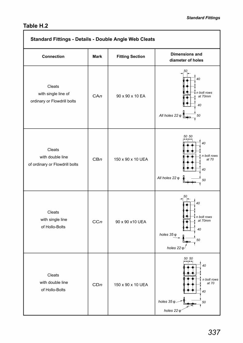
Standard Fittings
337
Table H.2
Standard Fittings - Details - Double Angle Web Cleats
Connection Mark Fitting SectionDimensions and
diameter of holes
Cleats
with single line ofCAn 90 x 90 x 10 EA
ordinary or Flowdrill bolts
Cleats
with double lineCBn 150 x 90 x 10 UEA
of ordinary or Flowdrill bolts
Cleats
with single lineCCn 90 x 90 x10 UEA
of Hollo-Bolts
Cleats
with double lineCDn 150 x 90 x 10 UEA
of Hollo-Bolts
holes 35 φ40
n bolt rows at 70mm
40
50
50
holes 22 φ
40
n bolt rows at 70
40
50
50 50
All holes 22 φ
40
n bolt rows at 70
40
50
holes 22 φ
holes 35 φ
50 50
40
n bolt rows at 70mm
40
50
50
All holes 22 φ

Standard Fittings
338
Table H.3
Standard Fittings - Details - Flexible End Plates
Connection Mark Fitting SectionDimensions and
diameter of holes
Flexible End Plate
with ordinary or
Flowdrill bolts EAn 150 x 8 Flat
For beams ≤ 457x191UB
Flexible End Plate
with ordinary or
Flowdrill boltsEBn 200 x 10 Flat
For beams > 457x191UB
Flexible End Plate
with Hollo-Bolts ECn 180 x 8 Flat
For beams ≤ 457x191UB
Flexible End Plate
with Hollo-Bolts EDn 200 x 10 Flat
For beams > 457x191UB
40
n bolt rows at 70
40
90
All holes 22 φ
140
40
n bolt rows at 70
40
All holes 22 φ
All holes 35 φ
120
40
n bolt rows at 70
40
40
n bolt rows at 70
40
90
All holes 35 φ
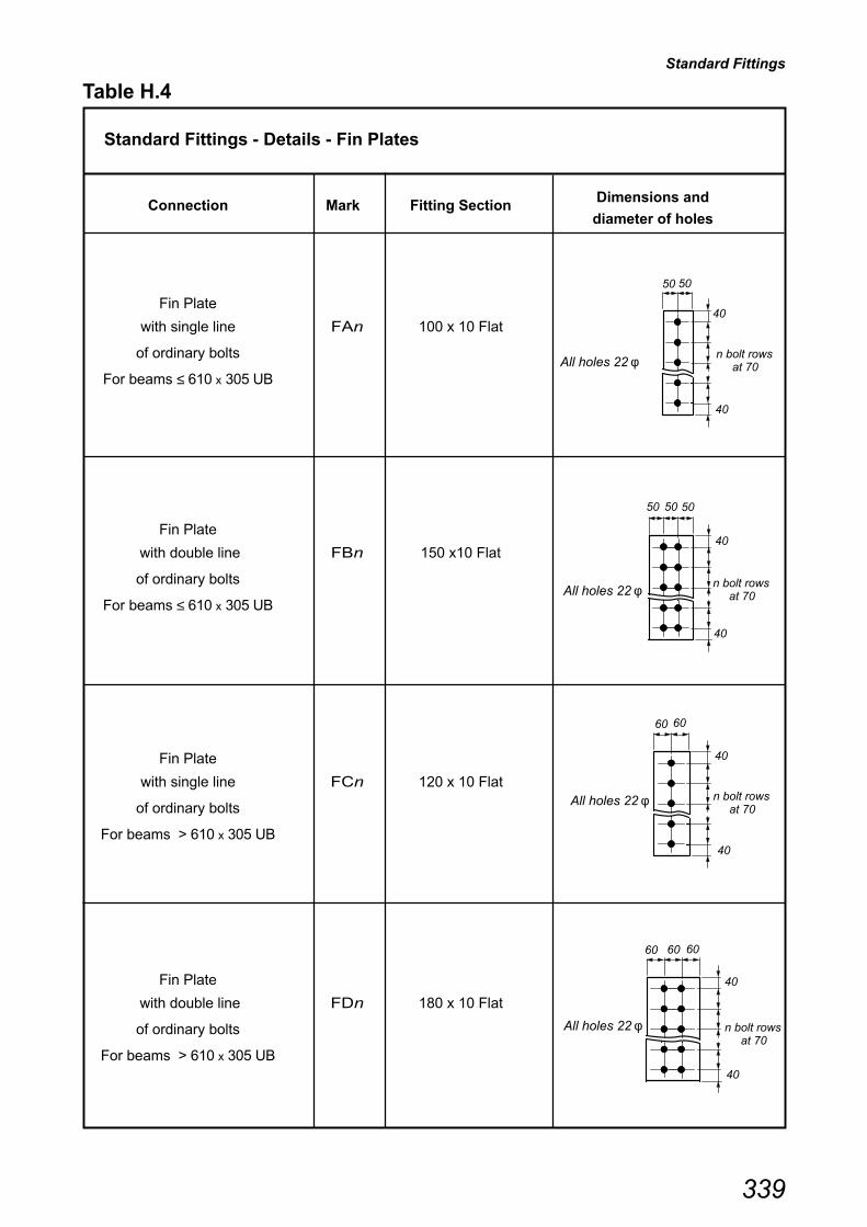
Standard Fittings
339
Table H.4
Standard Fittings - Details - Fin Plates
Connection Mark Fitting SectionDimensions and
diameter of holes
Fin Plate
with single line FAn 100 x 10 Flat
of ordinary bolts
For beams ≤ 610 x 305 UB
Fin Plate
with double line FBn 150 x10 Flat
of ordinary bolts
For beams ≤ 610 x 305 UB
Fin Plate
with single line FCn 120 x 10 Flat
of ordinary bolts
For beams > 610 x 305 UB
Fin Plate
with double line FDn 180 x 10 Flat
of ordinary bolts
For beams > 610 x 305 UB
40
n bolt rows at 70
40
50 50
All holes 22 φ
40
n bolt rows at 70
40
50 50 50
All holes 22 φ
40
n bolt rows at 70
40
60 60
All holes 22 φ
40
n bolt rows at 70
40
60 60 60
All holes 22 φ

Standard Fittings
340
Table H.5
Standard Fittings - Masses
Angle Web Cleats - Single vertical line of bolts (CA or CC)
Mark CA11 CA10 CA9 CA8 CA7 CA6 CA5 CA4 CA3 CA2
Size 90 x 90 x 10 Equal Angle (13.40 kg/m)
Length (mm) 780 710 640 570 500 430 360 290 220 150
Mass each (kg) 10.45 9.51 8.58 7.64 6.70 5.76 4.82 3.89 2.95 2.01
Angle Web Cleats - Double vertical line of bolts (CB or CD)
Mark CB11 CB10 CB9 CB8 CB7 CB6 CB5 CB4 CB3 CB2
Size 150 x 90 x 10 Unequal Angle (18.20 kg/m)
Length (mm) 780 710 640 570 500 430 360 290 220 150
Mass each (kg) 14.20 12.92 11.65 10.37 9.10 7.83 6.55 5.28 4.00 2.73
Flexible End Plates - Light
Mark EA5 EA4 EA3 EA2 EC5 EC4 EC3 EC2
Size 150 x 8 Flat (9.42 kg/m) 180 x 8 (11.30 kg/m)
Length (mm) 360 290 220 150 360 290 220 150
Mass each (kg) 3.39 2.73 2.07 1.41 4.07 3.28 2.48 1.70
Flexible End Plates - Heavy (EB or ED)
Mark EB11 EB10 EB9 EB8 EB7 EB6 EB5
Size 200 x 10 Flat (15.7 kg/m)
Length (mm) 780 710 640 570 500 430 360
Mass each (kg) 12.25 11.15 10.05 8.95 7.85 6.75 5.65
Fin Plates - Single vertical line of bolts
Mark FA7 FA6 FA5 FA4 FA3 FA2 FC11 FC10 FC9 FC8 FC7 FC6
Size 100 x 10 Flat (7.85 kg/m) 120 x 10 Flat (9.42 kg/m)
Length (mm) 500 430 360 290 220 150 780 710 640 570 500 430
Mass each (kg) 3.93 3.38 2.83 2.28 1.73 1.18 7.35 6.69 6.03 5.37 4.71 4.05
Fin Plates - Double vertical line of bolts
Mark FB7 FB6 FB5 FB4 FB3 FB2 FD11 FD10 FD9 FD8 FD7 FD6
Size 150 x 10 Flat (11.8 kg/m) 180 x 10 Flat (14.1 kg/m)
Length (mm) 500 430 360 290 220 150 780 710 640 570 500 430
Mass each (kg) 5.90 5.07 4.25 3.42 2.60 1.77 11.00 10.01 9.02 8.04 7.05 6.06
Double Angle Web Cleats
341
Table H.6
Explanatory notes - DOUBLE ANGLE WEB CLEATSUse of Capacity Tables
The following notes refer to the suffix numbers given at the top of the column descriptions for Tables H.9 to H.16.
The check numbers refer to those listed in Table H.8 and described in Section 4.5 Design procedures.
The capacity tables are based on the standard details given in Table H.7.
All universal beam sections which are suitable for the minimum standard fitting size and the standard notch sizeare shown in the tables (i.e. if T + r > 50 mm, section is not included).
(1) SHEAR CAPACITY OF THE BEAM
The value given in { } is the shear capacity of the beam, given by 0.6pytwD.
(2) SHEAR CAPACITY OF THE CONNECTION
This is the critical value of the design checks for the 'supported beam side' of the connection.i.e. the minimum capacity from CHECKS 2, 3(i), 3(ii), 4 (i), 4(ii), 4(iii), 8 and 9(ii).
For connections with Ordinary or Flowdrill bolts, Connection Shear Capacities are given for Un-notched orSingle notched and for Double notched beams.
For connections with Hollo-Bolts, connection shear capacities are tabulated for Un-notched beams only, asHollo-Bolts are used only with RHS columns and Un-notched beams.
(3) CRITICAL DESIGN CHECK
The check which gives the critical value of shear capacity. See Table H.8 for the description of the checks.
(4) FITTINGS
The length and type of Standard Double Angle fittings. See Tables H.1 and H.2 for details.
(5) MINIMUM SUPPORT THICKNESS
This is the minimum thickness of supporting column or beam element, that is needed to carry the givenSHEAR CAPACITY (Un-notched or Single Notched) of the connection. It is derived from CHECK 10 and ethas conservatively been taken as 90 mm.
For a symmetrical two sided connection, the minimum support thickness would be twice the tabulated value.
(6) MAXIMUM NOTCH LENGTH ( C + T1 )
These are maximum lengths of notches for single and double notched beams that can be accommodatedif the beam is to carry the tabulated corresponding SHEAR CAPACITY of the connection.
It is assumed that the beam is fully restrained against lateral torsional buckling, and the notched lengthsare derived from CHECKS 5 and 6.
To provide a simple check for double notched beams, it has been assumed that the remaining web depth,'y' (see Table H.7) is the same as the angle cleat length.
* Indicates that the condition from CHECK 6, i.e. dc2 ≤ D/5 is not satisfied.
For Hollo-Bolts,Tables H.13 to H.16, no values are tabulated for maximum notch lengths, since Hollo-Boltsare used only with RHS columns and un-notched beams.
(7) TYING CAPACITY
This is the critical value of the design checks for the 'supported beam' side of the connection,i.e. the minimum capacity from CHECKS 11, 12(i), 12(ii) and 13.
Values given in tables for CHECK 11 are those derived from the rigorous method of Appendix B and not theSimplified approach given in the design procedures. In CHECK 12 the supported beam is assumed to bedouble notched.
For Flowdrill connections, CHECK 13 will need to be carried out separately because the capacity isdependent on the thickness of the RHS.
Separate checks will have to be carried out on the supporting members (see CHECKS 14 and 15).
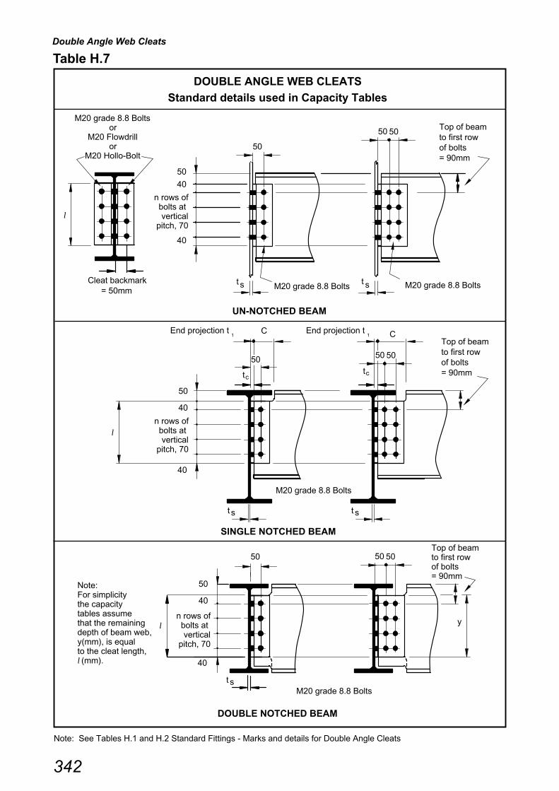
Double Angle Web Cleats
342
DOUBLE NOTCHED BEAM
UN-NOTCHED BEAM
SINGLE NOTCHED BEAM
Table H.7
DOUBLE ANGLE WEB CLEATS
Standard details used in Capacity Tables
Note: See Tables H.1 and H.2 Standard Fittings - Marks and details for Double Angle Cleats
st
y
Top of beamto first rowof bolts= 90mm
Cleat backmark
50
40
50
50
50
40
40
50
s
CEnd projection t1
= 50mm
l
50
40
40
40
Top of beam to first row of bolts = 90mm
Note: For simplicity the capacity tables assume that the remaining depth of beam web, y(mm), is equal to the cleat length, l (mm).
t
st
n rows of bolts at vertical
pitch, 70
n rows of bolts at vertical
pitch, 70
n rows of bolts at vertical
pitch, 70
M20 grade 8.8 Bolts
or M20 Flowdrill
or M20 Hollo-Bolt
M20 grade 8.8 Bolts M20 grade 8.8 Boltst s
M20 grade 8.8 Bolts
M20 grade 8.8 Bolts
= 90mmof boltsto first rowTop of beam
C
st
End projection t1
l
l
50 50
50 50
tctc
50 50

Double Angle Web Cleats
343
Check Number Description
2 Shear capacity of bolt group connected to supported beam
3(i) Shear capacity of angle cleats connected to supported beam
3(ii) Bearing capacity of angle cleats connected to supported beam
4(i) Shear capacity of supported beam at the connection
4(ii) Shear and bending interaction capacity of supported beam at the2nd bolt line connection
4(iii) Bearing capacity of supported beam web at the connection
8 Shear capacity of bolt group connected to supporting member
9(i) Shear capacity of angle cleats connected to supporting member
9(ii) Bearing capacity of angle cleats connected to supporting member
11 Tension capacity of angle cleats
(tables based on the rigorous approach of Appendix B)
12(i) Tension capacity of supported beam web at the connection
12(ii) Bearing capacity of supported beam web at the connection
13 Tension capacity of bolts in presence of extreme prying
SH
EA
R C
AP
AC
ITY
ST
RU
CT
UR
AL
INT
EG
RIT
Y
Su
pp
ort
ing
Su
pp
ort
ed
mem
ber
sid
e
b
eam
sid
e
Note: This table only lists the critical checks.
For a full list of design checks and further information, see Section 4.5.
Table H.8
DOUBLE ANGLE WEB CLEATS
Critical Check Description List

Double Angle Web Cleats
BEAM: S275 ANGLE CLEATS: S275
Table H.9 BOLTS: M20, 8.8
Beam SizeLength
�Mark S275 S355 Single Double Capacity
Critical Check
{ } (1)mm mm mm mm mm kN
914x305x253 11 1650 4 (iii) 1650 4 (iii) 780 CA11 8.1 6.8 517 155 1200 11
{2530 kN} 10 1480 4 (iii) 1480 4 (iii) 710 CA10 8.1 6.7 575 154 1090 11
9 1320 4 (iii) 1320 4 (iii) 640 CA9 8.0 6.6 648 152* 984 11
8 1150 4 (iii) 1150 4 (iii) 570 CA8 7.8 6.5 742 150* 877 11
914x305x224 11 1520 4 (iii) 1520 4 (iii) 780 CA11 7.5 6.3 505 155 1200 11
{2300 kN} 10 1360 4 (iii) 1360 4 (iii) 710 CA10 7.4 6.2 561 154 1090 11
9 1210 4 (iii) 1210 4 (iii) 640 CA9 7.3 6.1 632 152* 984 11
8 1060 4 (iii) 1060 4 (iii) 570 CA8 7.2 6.0 724 150* 877 11
914x305x201 11 1440 4 (iii) 1440 4 (iii) 780 CA11 7.1 5.9 489 155 1200 11
{2170 kN} 10 1290 4 (iii) 1290 4 (iii) 710 CA10 7.0 5.9 543 154 1090 11
9 1150 4 (iii) 1150 4 (iii) 640 CA9 6.9 5.8 612 152* 984 11
8 1000 4 (iii) 1000 4 (iii) 570 CA8 6.8 5.7 686 150* 877 11
838x292x226 10 1380 4 (iii) 1380 4 (iii) 710 CA10 7.5 6.3 495 154 1090 11
{2180 kN} 9 1230 4 (iii) 1230 4 (iii) 640 CA9 7.4 6.2 557 152 984 11
8 1070 4 (iii) 1070 4 (iii) 570 CA8 7.3 6.1 638 150* 877 11
838x292x194 10 1260 4 (iii) 1260 4 (iii) 710 CA10 6.8 5.7 476 154 1090 11
{1960 kN} 9 1120 4 (iii) 1120 4 (iii) 640 CA9 6.8 5.7 536 152 984 11
8 977 4 (iii) 977 4 (iii) 570 CA8 6.6 5.6 614 150* 877 11
838x292x176 10 1200 4 (iii) 1200 4 (iii) 710 CA10 6.5 5.5 464 154 1090 11
{1860 kN} 9 1070 4 (iii) 1070 4 (iii) 640 CA9 6.4 5.4 522 152 984 11
8 930 4 (iii) 930 4 (iii) 570 CA8 6.3 5.3 598 150* 877 11
762x267x197 9 1190 4 (iii) 1190 4 (iii) 640 CA9 7.2 6.0 449 152 984 11
{1910 kN} 8 1040 4 (iii) 1040 4 (iii) 570 CA8 7.0 5.9 514 150 877 11
7 886 4 (iii) 886 4 (iii) 500 CA7 6.9 5.8 602 148* 769 11
762x267x173 9 1090 4 (iii) 1090 4 (iii) 640 CA9 6.6 5.5 436 152 984 11
{1730 kN} 8 950 4 (iii) 950 4 (iii) 570 CA8 6.5 5.4 500 150 877 11
7 812 4 (iii) 812 4 (iii) 500 CA7 6.3 5.3 585 148* 769 11
762x267x147 9 974 4 (iii) 974 4 (iii) 640 CA9 5.9 4.9 422 152 984 11
{1530 kN} 8 851 4 (iii) 851 4 (iii) 570 CA8 5.8 4.8 484 150 877 11
7 727 4 (iii) 727 4 (iii) 500 CA7 5.6 4.7 566 148* 769 11
762x267x134 9 913 4 (iii) 913 4 (iii) 640 CA9 5.5 4.6 430 181 984 11
{1490 kN} 8 797 4 (iii) 797 4 (iii) 570 CA8 5.4 4.5 493 175 877 11
7 681 4 (iii) 681 4 (iii) 500 CA7 5.3 4.4 502 169* 769 11
For guidance on the use of tables see Explanatory notes in Table H.6
Shear(2)
Capacity kN
Double NotchMax Notch(6)
Length c+t1
Critical(3)
Design Check
DOUBLE ANGLE CLEATS, ORDINARY or FLOWDRILL BOLTS
Single line of bolts2 No. 90x90x10mm Equal Angles
Fitting(4)
Angle CleatsMin. Support(5)
ThicknessTying(7)
Bolt Rows
n
Un-notched or Single Notch
Shear(2)
Capacity kN
Critical(3)
Design Check
344

Double Angle Web Cleats
BEAM: S275 ANGLE CLEATS: S275
Table H.9 Continued BOLTS: M20, 8.8
Beam SizeLength
�Mark S275 S355 Single Double Capacity
Critical Check
{ } (1)mm mm mm mm mm kN
Shear(2)
Capacity kN
Double NotchMax Notch(6)
Length c+t1
Critical(3)
Design Check
DOUBLE ANGLE CLEATS, ORDINARY or FLOWDRILL BOLTS
Single line of bolts2 No. 90x90x10mm Equal Angles
Fitting(4)
Angle CleatsMin. Support(5)
ThicknessTying(7)
Bolt Rows
n
Un-notched or Single Notch
Shear(2)
Capacity kN
Critical(3)
Design Check
686x254x170 8 964 4 (iii) 964 4 (iii) 570 CA8 6.5 5.5 414 150 877 11
{1600 kN} 7 823 4 (iii) 823 4 (iii) 500 CA7 6.4 5.3 485 148* 769 11
6 683 4 (iii) 683 4 (iii) 430 CA6 6.2 5.2 584 145* 662 11
686x254x152 8 877 4 (iii) 877 4 (iii) 570 CA8 6.0 5.0 407 150 877 11
{1440 kN} 7 749 4 (iii) 749 4 (iii) 500 CA7 5.8 4.9 477 148 769 11
6 621 4 (iii) 621 4 (iii) 430 CA6 5.6 4.7 575 145* 662 11
686x254x140 8 824 4 (iii) 824 4 (iii) 570 CA8 5.6 4.7 401 150 877 11
{1350 kN} 7 704 4 (iii) 704 4 (iii) 500 CA7 5.5 4.6 469 148 769 11
6 584 4 (iii) 584 4 (iii) 430 CA6 5.3 4.4 566 145* 662 11
686x254x125 8 777 4 (iii) 777 4 (iii) 570 CA8 5.3 4.4 389 150 861 12 (ii)
{1260 kN} 7 664 4 (iii) 664 4 (iii) 500 CA7 5.2 4.3 456 148 753 12 (ii)
6 551 4 (iii) 551 4 (iii) 430 CA6 5.0 4.2 550 145* 646 12 (ii)
610x305x238 7 1040 4 (iii) 1040 4 (iii) 500 CA7 8.1 6.8 416 148 769 11
{1860 kN} 6 866 4 (iii) 866 4 (iii) 430 CA6 7.8 6.6 502 145* 662 11
610x305x179 7 800 4 (iii) 800 4 (iii) 500 CA7 6.2 5.2 399 148 769 11
{1390 kN} 6 664 4 (iii) 664 4 (iii) 430 CA6 6.0 5.0 481 145* 662 11
610x305x149 7 670 4 (iii) 670 4 (iii) 500 CA7 5.2 4.3 391 148 760 12 (ii)
{1150 kN} 6 556 4 (iii) 556 4 (iii) 430 CA6 5.0 4.2 471 145* 651 12 (ii)
610x229x140 7 744 4 (iii) 744 4 (iii) 500 CA7 5.8 4.8 380 148 769 11
{1290 kN} 6 617 4 (iii) 617 4 (iii) 430 CA6 5.6 4.7 458 145* 662 11
610x229x125 7 676 4 (iii) 676 4 (iii) 500 CA7 5.2 4.4 373 148 766 12 (ii)
{1160 kN} 6 560 4 (iii) 560 4 (iii) 430 CA6 5.1 4.2 450 145* 657 12 (ii)
610x229x113 7 630 4 (iii) 630 4 (iii) 500 CA7 4.9 4.1 366 148 715 12 (ii)
{1070 kN} 6 523 4 (iii) 523 4 (iii) 430 CA6 4.7 4.0 441 145* 613 12 (ii)
610x229x101 7 596 4 (iii) 596 4 (iii) 500 CA7 4.6 3.9 369 169 676 12 (ii)
{1040 kN} 6 494 4 (iii) 494 4 (iii) 430 CA6 4.5 3.7 444 162* 580 12 (ii)
For guidance on the use of tables see Explanatory notes in Table H.6
345

Double Angle Web Cleats
BEAM: S275 ANGLE CLEATS: S275
Table H.9 Continued BOLTS: M20, 8.8
Beam SizeLength
�Mark S275 S355 Single Double Capacity
Critical Check
{ } (1)mm mm mm mm mm kN
Shear(2)
Capacity kN
Double NotchMax Notch(6)
Length c+t1
Critical(3)
Design Check
DOUBLE ANGLE CLEATS, ORDINARY or FLOWDRILL BOLTS
Single line of bolts2 No. 90x90x10mm Equal Angles
Fitting(4)
Angle CleatsMin. Support(5)
ThicknessTying(7)
Bolt Rows
n
Un-notched or Single Notch
Shear(2)
Capacity kN
Critical(3)
Design Check
533x210x122 6 598 4 (iii) 598 4 (iii) 430 CA6 5.4 4.5 349 145 662 11
{1100 kN} 5 475 4 (iii) 475 4 (iii) 360 CA5 5.2 4.3 439 142* 555 11
533x210x109 6 546 4 (iii) 546 4 (iii) 430 CA6 4.9 4.1 342 145 640 12 (ii)
{995 kN} 5 434 4 (iii) 434 4 (iii) 360 CA5 4.7 3.9 430 142* 534 12 (ii)
533x210x101 6 508 4 (iii) 508 4 (iii) 430 CA6 4.6 3.9 339 145 596 12 (ii)
{922 kN} 5 404 4 (iii) 404 4 (iii) 360 CA5 4.4 3.7 426 142* 497 12 (ii)
533x210x92 6 475 4 (iii) 475 4 (iii) 430 CA6 4.3 3.6 346 162 558 12 (ii)
{888 kN} 5 378 4 (iii) 378 4 (iii) 360 CA5 4.1 3.4 435 155* 465 12 (ii)
533x210x82 6 452 4 (iii) 452 4 (iii) 430 CA6 4.1 3.4 334 162 530 12 (ii)
{837 kN} 5 359 4 (iii) 359 4 (iii) 360 CA5 3.9 3.3 421 155* 442 12 (ii)
457x191x98 5 427 4 (iii) 427 4 (iii) 360 CA5 4.6 3.9 316 142 524 12 (ii)
{847 kN} 4 319 4 (iii) 319 4 (iii) 290 CA4 4.3 3.6 424 133* 420 12 (ii)
457x191x89 5 393 4 (iii) 393 4 (iii) 360 CA5 4.3 3.6 311 142 483 12 (ii)
{774 kN} 4 293 4 (iii) 293 4 (iii) 290 CA4 4.0 3.3 417 133* 386 12 (ii)
457x191x82 5 371 4 (iii) 371 4 (iii) 360 CA5 4.0 3.4 317 155 455 12 (ii)
{751 kN} 4 277 4 (iii) 277 4 (iii) 290 CA4 3.8 3.1 424 138* 364 12 (ii)
457x191x74 5 337 4 (iii) 337 4 (iii) 360 CA5 3.7 3.1 313 155 414 12 (ii)
{679 kN} 4 251 4 (iii) 251 4 (iii) 290 CA4 3.4 2.9 420 138* 331 12 (ii)
457x191x67 5 318 4 (iii) 318 4 (iii) 360 CA5 3.5 2.9 306 155 391 12 (ii)
{636 kN} 4 237 4 (iii) 237 4 (iii) 290 CA4 3.2 2.7 410 138* 313 12 (ii)
For guidance on the use of tables see Explanatory notes in Table H.6
346

Double Angle Web Cleats
BEAM: S275 ANGLE CLEATS: S275
Table H.9 Continued BOLTS: M20, 8.8
Beam SizeLength
�Mark S275 S355 Single Double Capacity
Critical Check
{ } (1)mm mm mm mm mm kN
Shear(2)
Capacity kN
Double NotchMax Notch(6)
Length c+t1
Critical(3)
Design Check
DOUBLE ANGLE CLEATS, ORDINARY or FLOWDRILL BOLTS
Single line of bolts2 No. 90x90x10mm Equal Angles
Fitting(4)
Angle CleatsMin. Support(5)
ThicknessTying(7)
Bolt Rows
n
Un-notched or Single Notch
Shear(2)
Capacity kN
Critical(3)
Design Check
457x152x82 5 393 4 (iii) 393 4 (iii) 360 CA5 4.3 3.6 306 142 483 12 (ii)
{778 kN} 4 293 4 (iii) 293 4 (iii) 290 CA4 4.0 3.3 411 133* 386 12 (ii)
457x152x74 5 359 4 (iii) 359 4 (iii) 360 CA5 3.9 3.3 301 142 442 12 (ii)
{705 kN} 4 268 4 (iii) 268 4 (iii) 290 CA4 3.6 3.0 404 133* 353 12 (ii)
457x152x67 5 337 4 (iii) 337 4 (iii) 360 CA5 3.7 3.1 305 155 414 12 (ii)
{680 kN} 4 251 4 (iii) 251 4 (iii) 290 CA4 3.4 2.9 409 138* 331 12 (ii)
457x152x60 5 303 4 (iii) 303 4 (iii) 360 CA5 3.3 2.8 301 155 373 12 (ii)
{608 kN} 4 226 4 (iii) 226 4 (iii) 290 CA4 3.1 2.6 403 138* 298 12 (ii)
457x152x52 5 284 4 (iii) 284 4 (iii) 360 CA5 3.1 2.6 289 155 350 12 (ii)
{564 kN} 4 212 4 (iii) 212 4 (iii) 290 CA4 2.9 2.4 357 138* 280 12 (ii)
406x178x74 4 265 4 (iii) 265 4 (iii) 290 CA4 3.6 3.0 336 138 350 12 (ii)
{647 kN}
406x178x67 4 246 4 (iii) 246 4 (iii) 290 CA4 3.3 2.8 329 138 324 12 (ii)
{594 kN}
406x178x60 4 221 4 (iii) 221 4 (iii) 290 CA4 3.0 2.5 325 138 291 12 (ii)
{530 kN}
406x178x54 4 215 4 (iii) 215 4 (iii) 290 CA4 2.9 2.4 314 138 283 12 (ii)
{512 kN}
406x140x46 4 190 4 (iii) 190 4 (iii) 290 CA4 2.6 2.2 311 138 250 12 (ii)
{452 kN}
406x140x39 4 179 4 (iii) 179 4 (iii) 290 CA4 2.4 2.0 275 138 236 12 (ii)
{420 kN}
356x171x67 3 171 4 (iii) 171 4 (iii) 220 CA3 3.1 2.6 373 118* 251 12 (ii)
{546 kN}
356x171x57 3 153 4 (iii) 153 4 (iii) 220 CA3 2.8 2.3 364 118* 224 12 (ii)
{478 kN}
356x171x51 3 139 4 (iii) 139 4 (iii) 220 CA3 2.5 2.1 357 118* 204 12 (ii)
{433 kN}
356x171x45 3 132 4 (iii) 132 4 (iii) 220 CA3 2.4 2.0 345 118* 193 12 (ii)
{406 kN}
356x127x39 3 124 4 (iii) 124 4 (iii) 220 CA3 2.3 1.9 340 118* 182 12 (ii)
{385 kN}
356x127x33 3 113 4 (iii) 113 4 (iii) 220 CA3 2.0 1.7 294 118* 166 12 (ii)
{346 kN}
For guidance on the use of tables see Explanatory notes in Table H.6
347

Double Angle Web Cleats
BEAM: S275 ANGLE CLEATS: S275
Table H.9 Continued BOLTS: M20, 8.8
Beam SizeLength
�Mark S275 S355 Single Double Capacity
Critical Check
{ } (1)mm mm mm mm mm kN
Shear(2)
Capacity kN
Double NotchMax Notch(6)
Length c+t1
Critical(3)
Design Check
DOUBLE ANGLE CLEATS, ORDINARY or FLOWDRILL BOLTS
Single line of bolts2 No. 90x90x10mm Equal Angles
Fitting(4)
Angle CleatsMin. Support(5)
ThicknessTying(7)
Bolt Rows
n
Un-notched or Single Notch
Shear(2)
Capacity kN
Critical(3)
Design Check
305x165x54 3 149 4 (iii) 149 4 (iii) 220 CA3 2.7 2.3 265 118 218 12 (ii)
{405 kN}
305x165x46 3 126 4 (iii) 126 4 (iii) 220 CA3 2.3 1.9 260 118 185 12 (ii)
{339 kN}
305x165x40 3 113 4 (iii) 113 4 (iii) 220 CA3 2.0 1.7 254 118 166 12 (ii)
{300 kN}
305x127x48 3 169 4 (iii) 169 4 (iii) 220 CA3 3.1 2.6 251 118 248 12 (ii)
{462 kN}
305x127x42 3 151 4 (iii) 151 4 (iii) 220 CA3 2.7 2.3 245 118 221 12 (ii)
{406 kN}
305x127x37 3 134 4 (iii) 134 4 (iii) 220 CA3 2.4 2.0 241 118 196 12 (ii)
{357 kN}
305x102x33 3 124 4 (iii) 124 4 (iii) 220 CA3 2.3 1.9 251 118 182 12 (ii)
{341 kN}
305x102x28 3 113 4 (iii) 113 4 (iii) 220 CA3 2.0 1.7 241 118 166 12 (ii)
{306 kN}
305x102x25 3 109 4 (iii) 109 4 (iii) 220 CA3 2.0 1.7 229 118 160 12 (ii)
{292 kN}
254x146x43 2 76 4 (iii) 76 4 (iii) 150 CA2 2.1 1.7 270 98* 132 12 (ii)
{308 kN}
254x146x37 2 66 4 (iii) 66 4 (iii) 150 CA2 1.8 1.5 266 98* 116 12 (ii)
{266 kN}
254x146x31 2 63 4 (iii) 63 4 (iii) 150 CA2 1.7 1.4 261 98* 110 12 (ii)
{249 kN}
254x102x28 2 66 4 (iii) 66 4 (iii) 150 CA2 1.8 1.5 270 98* 116 12 (ii)
{271 kN}
254x102x25 2 63 4 (iii) 63 4 (iii) 150 CA2 1.7 1.4 267 98* 110 12 (ii)
{255 kN}
254x102x22 2 60 4 (iii) 60 4 (iii) 150 CA2 1.6 1.4 264 98* 105 12 (ii)
{239 kN}
For guidance on the use of tables see Explanatory notes in Table H.6
348
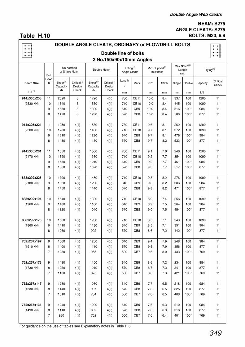
Double Angle Web Cleats
BEAM: S275 ANGLE CLEATS: S275
Table H.10 BOLTS: M20, 8.8
Beam SizeLength
�Mark S275 S355 Single Double Capacity
Critical Check
{ } (1)mm mm mm mm mm kN
914x305x253 11 2020 8 1720 4(ii) 780 CB11 10.0 8.4 337 100 1200 11
{2530 kN} 10 1840 8 1550 4(ii) 710 CB10 10.0 8.4 445 100 1090 11
9 1650 8 1390 4(ii) 640 CB9 10.0 8.4 516 100* 984 11
8 1470 8 1230 4(ii) 570 CB8 10.0 8.4 580 100* 877 11
914x305x224 11 1950 4(ii) 1580 4(ii) 780 CB11 9.6 8.1 262 100 1200 11
{2300 kN} 10 1780 4(ii) 1430 4(ii) 710 CB10 9.7 8.1 372 100 1090 11
9 1610 4(ii) 1280 4(ii) 640 CB9 9.7 8.1 476 100* 984 11
8 1430 4(ii) 1130 4(ii) 570 CB8 9.7 8.2 533 100* 877 11
914x305x201 11 1850 4(ii) 1500 4(ii) 780 CB11 9.1 7.6 246 100 1200 11
{2170 kN} 10 1690 4(ii) 1360 4(ii) 710 CB10 9.2 7.7 354 100 1090 11
9 1530 4(ii) 1210 4(ii) 640 CB9 9.2 7.7 461 100* 984 11
8 1360 4(ii) 1070 4(ii) 570 CB8 9.3 7.7 517 100* 877 11
838x292x226 10 1790 4(ii) 1450 4(ii) 710 CB10 9.8 8.2 276 100 1090 11
{2180 kN} 9 1620 4(ii) 1290 4(ii) 640 CB9 9.8 8.2 386 100 984 11
8 1450 4(ii) 1140 4(ii) 570 CB8 9.8 8.2 471 100* 877 11
838x292x194 10 1640 4(ii) 1320 4(ii) 710 CB10 8.9 7.4 256 100 1090 11
{1960 kN} 9 1480 4(ii) 1180 4(ii) 640 CB9 8.9 7.5 364 100 984 11
8 1320 4(ii) 1040 4(ii) 570 CB8 9.0 7.5 454 100* 877 11
838x292x176 10 1560 4(ii) 1260 4(ii) 710 CB10 8.5 7.1 243 100 1090 11
{1860 kN} 9 1410 4(ii) 1130 4(ii) 640 CB9 8.5 7.1 351 100 984 11
8 1260 4(ii) 992 4(ii) 570 CB8 8.6 7.2 442 100* 877 11
762x267x197 9 1560 4(ii) 1250 4(ii) 640 CB9 9.4 7.9 248 100 984 11
{1910 kN} 8 1400 4(ii) 1110 4(ii) 570 CB8 9.5 7.9 356 100 877 11
7 1230 4(ii) 955 4(ii) 500 CB7 9.6 8.0 433 100* 769 11
762x267x173 9 1430 4(ii) 1150 4(ii) 640 CB9 8.6 7.2 234 100 984 11
{1730 kN} 8 1280 4(ii) 1010 4(ii) 570 CB8 8.7 7.3 341 100 877 11
7 1130 4(ii) 875 4(ii) 500 CB7 8.8 7.3 421 100* 769 11
762x267x147 9 1280 4(ii) 1030 4(ii) 640 CB9 7.7 6.5 218 100 984 11
{1530 kN} 8 1140 4(ii) 907 4(ii) 570 CB8 7.8 6.5 325 100 877 11
7 1010 4(ii) 784 4(ii) 500 CB7 7.8 6.5 408 100* 769 11
762x267x134 9 1240 4(ii) 1000 4(ii) 640 CB9 7.5 6.3 210 100 984 11
{1490 kN} 8 1110 4(ii) 882 4(ii) 570 CB8 7.6 6.3 316 100 877 11
7 980 4(ii) 762 4(ii) 500 CB7 7.6 6.4 401 100* 769 11
For guidance on the use of tables see Explanatory notes in Table H.6
Shear(2)
Capacity kN
Double NotchMax Notch(6)
Length c+t1
Critical(3)
Design Check
DOUBLE ANGLE CLEATS, ORDINARY or FLOWDRILL BOLTS
Double line of bolts2 No.150x90x10mm Angles
Fitting(4)
Angle CleatsMin. Support(5)
ThicknessTying(7)
Bolt Rows
n
Un-notched or Single Notch
Shear(2)
Capacity kN
Critical(3)
Design Check
349

Double Angle Web Cleats
BEAM: S275 ANGLE CLEATS: S275
Table H.10 Continued BOLTS: M20, 8.8
Beam SizeLength
�Mark S275 S355 Single Double Capacity
Critical Check
{ } (1)mm mm mm mm mm kN
Shear(2)
Capacity kN
Double NotchMax Notch(6)
Length c+t1
Critical(3)
Design Check
DOUBLE ANGLE CLEATS, ORDINARY or FLOWDRILL BOLTS
Double line of bolts2 No.150x90x10mm Angles
Fitting(4)
Angle CleatsMin. Support(5)
ThicknessTying(7)
Bolt Rows
n
Un-notched or Single Notch
Shear(2)
Capacity kN
Critical(3)
Design Check
686x254x170 8 1290 4(ii) 1030 4(ii) 570 CB8 8.7 7.3 230 100 877 11
{1600 kN} 7 1140 4(ii) 888 4(ii) 500 CB7 8.8 7.4 338 100* 769 11
6 982 4(ii) 747 4(ii) 430 CB6 8.9 7.4 406 100* 662 11
686x254x152 8 1170 4(ii) 935 4(ii) 570 CB8 8.0 6.7 221 100 877 11
{1440 kN} 7 1030 4(ii) 808 4(ii) 500 CB7 8.0 6.7 329 100 769 11
6 894 4(ii) 680 4(ii) 430 CB6 8.1 6.8 399 100* 662 11
686x254x140 8 1100 4(ii) 878 4(ii) 570 CB8 7.5 6.2 214 100 877 11
{1350 kN} 7 971 4(ii) 759 4(ii) 500 CB7 7.5 6.3 321 100 769 11
6 839 4(ii) 639 4(ii) 430 CB6 7.6 6.4 394 100* 662 11
686x254x125 8 1040 4(ii) 829 4(ii) 570 CB8 7.0 5.9 202 100 877 11
{1260 kN} 7 915 4(ii) 716 4(ii) 500 CB7 7.1 5.9 309 100 769 11
6 791 4(ii) 603 4(ii) 430 CB6 7.2 6.0 383 100* 662 11
610x305x238 7 1290 8 1130 4(ii) 500 CB7 10.0 8.4 335 100 769 11
{1860 kN} 6 1100 8 948 4(ii) 430 CB6 10.0 8.4 395 100* 662 11
610x305x179 7 1100 4(ii) 863 4(ii) 500 CB7 8.5 7.1 225 100 769 11
{1390 kN} 6 949 4(ii) 726 4(ii) 430 CB6 8.6 7.2 336 100* 662 11
610x305x149 7 916 4(ii) 722 4(ii) 500 CB7 7.1 5.9 213 100 769 11
{1150 kN} 6 794 4(ii) 608 4(ii) 430 CB6 7.2 6.0 326 100* 662 11
610x229x140 7 1020 4(ii) 802 4(ii) 500 CB7 7.9 6.6 213 100 769 11
{1290 kN} 6 880 4(ii) 675 4(ii) 430 CB6 8.0 6.7 321 100* 662 11
610x229x125 7 921 4(ii) 729 4(ii) 500 CB7 7.2 6.0 205 100 769 11
{1160 kN} 6 799 4(ii) 613 4(ii) 430 CB6 7.2 6.1 313 100* 662 11
610x229x113 7 858 4(ii) 680 4(ii) 500 CB7 6.7 5.6 197 100 769 11
{1070 kN} 6 745 4(ii) 572 4(ii) 430 CB6 6.7 5.6 303 100* 662 11
610x229x101 7 841 4(ii) 667 4(ii) 500 CB7 6.5 5.5 187 100 769 11
{1040 kN} 6 730 4(ii) 561 4(ii) 430 CB6 6.6 5.5 292 100* 662 11
For guidance on the use of tables see Explanatory notes in Table H.6
350

Double Angle Web Cleats
BEAM: S275 ANGLE CLEATS: S275
Table H.10 Continued BOLTS: M20, 8.8
Beam SizeLength
�Mark S275 S355 Single Double Capacity
Critical Check
{ } (1)mm mm mm mm mm kN
Shear(2)
Capacity kN
Double NotchMax Notch(6)
Length c+t1
Critical(3)
Design Check
DOUBLE ANGLE CLEATS, ORDINARY or FLOWDRILL BOLTS
Double line of bolts2 No.150x90x10mm Angles
Fitting(4)
Angle CleatsMin. Support(5)
ThicknessTying(7)
Bolt Rows
n
Un-notched or Single Notch
Shear(2)
Capacity kN
Critical(3)
Design Check
533x210x122 6 840 4(ii) 654 4(ii) 430 CB6 7.6 6.4 201 100 662 11
{1100 kN} 5 712 4(ii) 529 4(ii) 360 CB5 7.7 6.5 293 100* 555 11
533x210x109 6 766 4(ii) 597 4(ii) 430 CB6 6.9 5.8 193 100 662 11
{995 kN} 5 649 4(ii) 483 4(ii) 360 CB5 7.1 5.9 288 100* 555 11
533x210x101 6 713 4(ii) 556 4(ii) 430 CB6 6.5 5.4 189 100 662 11
{922 kN} 5 604 4(ii) 450 4(ii) 360 CB5 6.6 5.5 285 100* 555 11
533x210x92 6 691 4(ii) 540 4(ii) 430 CB6 6.3 5.2 183 100 662 11
{888 kN} 5 586 4(ii) 437 4(ii) 360 CB5 6.4 5.3 280 100* 555 11
533x210x82 6 655 4(ii) 513 4(ii) 430 CB6 5.9 5.0 174 100 662 11
{837 kN} 5 556 4(ii) 415 4(ii) 360 CB5 6.0 5.1 272 100* 555 11
457x191x98 5 624 4(ii) 475 4(ii) 360 CB5 6.8 5.7 183 100 555 11
{847 kN} 4 485 4 (iii) 361 4(ii) 290 CB4 6.6 5.5 278 100* 448 11
457x191x89 5 574 4(ii) 437 4(ii) 360 CB5 6.2 5.2 177 100 555 11
{774 kN} 4 447 4 (iii) 333 4(ii) 290 CB4 6.1 5.1 274 100* 448 11
457x191x82 5 561 4(ii) 428 4(ii) 360 CB5 6.1 5.1 172 100 555 11
{751 kN} 4 421 4 (iii) 325 4(ii) 290 CB4 5.7 4.8 279 100* 448 11
457x191x74 5 509 4(ii) 389 4(ii) 360 CB5 5.5 4.6 168 100 555 11
{679 kN} 4 383 4 (iii) 296 4(ii) 290 CB4 5.2 4.4 276 100* 448 11
457x191x67 5 480 4(ii) 367 4(ii) 360 CB5 5.2 4.4 162 100 555 11
{636 kN} 4 362 4 (iii) 279 4(ii) 290 CB4 4.9 4.1 269 100* 448 11
For guidance on the use of tables see Explanatory notes in Table H.6
351

Double Angle Web Cleats
BEAM: S275 ANGLE CLEATS: S275
Table H.10 Continued BOLTS: M20, 8.8
Beam SizeLength
�Mark S275 S355 Single Double Capacity
Critical Check
{ } (1)mm mm mm mm mm kN
Shear(2)
Capacity kN
Double NotchMax Notch(6)
Length c+t1
Critical(3)
Design Check
DOUBLE ANGLE CLEATS, ORDINARY or FLOWDRILL BOLTS
Double line of bolts2 No.150x90x10mm Angles
Fitting(4)
Angle CleatsMin. Support(5)
ThicknessTying(7)
Bolt Rows
n
Un-notched or Single Notch
Shear(2)
Capacity kN
Critical(3)
Design Check
457x152x82 5 573 4(ii) 437 4(ii) 360 CB5 6.2 5.2 178 100 555 11
{778 kN} 4 447 4 (iii) 333 4(ii) 290 CB4 6.1 5.1 270 100* 448 11
457x152x74 5 523 4(ii) 400 4(ii) 360 CB5 5.7 4.8 172 100 555 11
{705 kN} 4 408 4 (iii) 304 4(ii) 290 CB4 5.5 4.6 265 100* 448 11
457x152x67 5 508 4(ii) 389 4(ii) 360 CB5 5.5 4.6 166 100 555 11
{680 kN} 4 383 4 (iii) 296 4(ii) 290 CB4 5.2 4.4 269 100* 448 11
457x152x60 5 456 4(ii) 350 4(ii) 360 CB5 5.0 4.1 161 100 555 11
{608 kN} 4 345 4 (iii) 266 4(ii) 290 CB4 4.7 3.9 265 100* 448 11
457x152x52 5 426 4(ii) 329 4(ii) 360 CB5 4.6 3.9 153 100 555 11
{564 kN} 4 323 4 (iii) 250 4(ii) 290 CB4 4.4 3.7 255 100* 448 11
406x178x74 4 404 4 (iii) 312 4(ii) 290 CB4 5.5 4.6 221 100 448 11
{647 kN}
406x178x67 4 374 4 (iii) 289 4(ii) 290 CB4 5.1 4.3 216 100 448 11
{594 kN}
406x178x60 4 336 4 (iii) 260 4(ii) 290 CB4 4.6 3.8 214 100 448 11
{530 kN}
406x178x54 4 328 4 (iii) 253 4(ii) 290 CB4 4.5 3.7 206 100 448 11
{512 kN}
406x140x46 4 289 4 (iii) 224 4(ii) 290 CB4 3.9 3.3 204 100 415 12 (i)
{452 kN}
406x140x39 4 272 4 (iii) 210 4(ii) 290 CB4 3.7 3.1 194 100 391 12 (i)
{420 kN}
356x171x67 3 251 4 (iii) 202 4(ii) 220 CB3 4.5 3.8 258 100* 340 11
{546 kN}
356x171x57 3 223 4 (iii) 180 4(ii) 220 CB3 4.0 3.4 249 100* 340 11
{478 kN}
356x171x51 3 204 4 (iii) 164 4(ii) 220 CB3 3.7 3.1 244 100* 340 11
{433 kN}
356x171x45 3 193 4 (iii) 155 4(ii) 220 CB3 3.5 2.9 236 100* 335 12 (i)
{406 kN}
356x127x39 3 182 4 (iii) 146 4(ii) 220 CB3 3.3 2.8 232 100* 316 12 (i)
{385 kN}
356x127x33 3 165 4 (iii) 133 4(ii) 220 CB3 3.0 2.5 223 100* 287 12 (i)
{346 kN}
For guidance on the use of tables see Explanatory notes in Table H.6
352

Double Angle Web Cleats
BEAM: S275 ANGLE CLEATS: S275
Table H.10 Continued BOLTS: M20, 8.8
Beam SizeLength
�Mark S275 S355 Single Double Capacity
Critical Check
{ } (1)mm mm mm mm mm kN
Shear(2)
Capacity kN
Double NotchMax Notch(6)
Length c+t1
Critical(3)
Design Check
DOUBLE ANGLE CLEATS, ORDINARY or FLOWDRILL BOLTS
Double line of bolts2 No.150x90x10mm Angles
Fitting(4)
Angle CleatsMin. Support(5)
ThicknessTying(7)
Bolt Rows
n
Un-notched or Single Notch
Shear(2)
Capacity kN
Critical(3)
Design Check
305x165x54 3 218 4 (iii) 175 4(ii) 220 CB3 3.9 3.3 181 100 340 11
{405 kN}
305x165x46 3 185 4 (iii) 149 4(ii) 220 CB3 3.3 2.8 178 100 321 12 (i)
{339 kN}
305x165x40 3 165 4 (iii) 133 4(ii) 220 CB3 3.0 2.5 173 100 287 12 (i)
{300 kN}
305x127x48 3 248 4 (iii) 200 4(ii) 220 CB3 4.5 3.8 172 100 340 11
{462 kN}
305x127x42 3 220 4 (iii) 177 4(ii) 220 CB3 4.0 3.3 167 100 340 11
{406 kN}
305x127x37 3 196 4 (iii) 158 4(ii) 220 CB3 3.5 3.0 164 100 340 12 (i)
{357 kN}
305x102x33 3 182 4 (iii) 146 4(ii) 220 CB3 3.3 2.8 172 100 316 12 (i)
{341 kN}
305x102x28 3 165 4 (iii) 133 4(ii) 220 CB3 3.0 2.5 165 100 287 12 (i)
{306 kN}
305x102x25 3 160 4 (iii) 129 4(ii) 220 CB3 2.9 2.4 157 100 278 12 (i)
{292 kN}
254x146x43 2 108 4 (iii) 74 4(ii) 150 CB2 2.9 2.4 218 100* 233 11
{308 kN}
254x146x37 2 94 4 (iii) 65 4(ii) 150 CB2 2.6 2.1 212 100* 218 12 (i)
{266 kN}
254x146x31 2 90 4 (iii) 62 4(ii) 150 CB2 2.4 2.0 200 100* 208 12 (i)
{249 kN}
254x102x28 2 94 4 (iii) 65 4(ii) 150 CB2 2.6 2.1 208 100* 218 12 (i)
{271 kN}
254x102x25 2 90 4 (iii) 62 4(ii) 150 CB2 2.4 2.0 200 100* 208 12 (i)
{255 kN}
254x102x22 2 85 4 (iii) 59 4(ii) 150 CB2 2.3 1.9 190 100* 198 12 (i)
{239 kN}
For guidance on the use of tables see Explanatory notes in Table H.6
353

Double Angle Web Cleats
BEAM: S355 ANGLE CLEATS: S275
Table H.11 BOLTS: M20, 8.8
Beam SizeLength
�Mark S275 S355 Single Double Capacity
Critical Check
{ } (1)mm mm mm mm mm kN
914x305x253 11 1900 2 1900 2 780 CA11 9.4 7.9 584 207 1200 11
{3290 kN} 10 1710 2 1710 2 710 CA10 9.3 7.8 649 201 1090 11
9 1520 2 1520 2 640 CA9 9.2 7.7 685 195* 984 11
8 1330 2 1330 2 570 CA8 9.0 7.5 685 188* 877 11
914x305x224 11 1810 4 (iii) 1810 4 (iii) 780 CA11 9.0 7.5 543 166 1200 11
{3000 kN} 10 1630 4 (iii) 1630 4 (iii) 710 CA10 8.9 7.4 543 165 1090 11
9 1450 4 (iii) 1450 4 (iii) 640 CA9 8.7 7.3 543 164* 984 11
8 1260 4 (iii) 1260 4 (iii) 570 CA8 8.6 7.2 543 163* 877 11
914x305x201 11 1720 4 (iii) 1720 4 (iii) 780 CA11 8.5 7.1 474 166 1200 11
{2820 kN} 10 1550 4 (iii) 1550 4 (iii) 710 CA10 8.4 7.0 474 165 1090 11
9 1370 4 (iii) 1370 4 (iii) 640 CA9 8.3 6.9 474 164* 984 11
8 1200 4 (iii) 1200 4 (iii) 570 CA8 8.2 6.8 474 163* 877 11
838x292x226 10 1650 4 (iii) 1650 4 (iii) 710 CA10 9.0 7.5 539 165 1090 11
{2840 kN} 9 1470 4 (iii) 1470 4 (iii) 640 CA9 8.8 7.4 607 164 984 11
8 1280 4 (iii) 1280 4 (iii) 570 CA8 8.7 7.3 644 163* 877 11
838x292x194 10 1510 4 (iii) 1510 4 (iii) 710 CA10 8.2 6.8 504 165 1090 11
{2560 kN} 9 1340 4 (iii) 1340 4 (iii) 640 CA9 8.1 6.8 504 164 984 11
8 1170 4 (iii) 1170 4 (iii) 570 CA8 7.9 6.6 504 163* 877 11
838x292x176 10 1430 4 (iii) 1430 4 (iii) 710 CA10 7.8 6.5 443 165 1090 11
{2420 kN} 9 1270 4 (iii) 1270 4 (iii) 640 CA9 7.7 6.4 443 164 984 11
8 1110 4 (iii) 1110 4 (iii) 570 CA8 7.6 6.3 443 163* 877 11
762x267x197 9 1420 4 (iii) 1420 4 (iii) 640 CA9 8.6 7.2 489 164 984 11
{2490 kN} 8 1240 4 (iii) 1240 4 (iii) 570 CA8 8.4 7.0 560 163 877 11
7 1060 4 (iii) 1060 4 (iii) 500 CA7 8.2 6.9 655 160* 769 11
762x267x173 9 1300 4 (iii) 1300 4 (iii) 640 CA9 7.9 6.6 475 164 984 11
{2260 kN} 8 1140 4 (iii) 1140 4 (iii) 570 CA8 7.7 6.5 544 163 877 11
7 971 4 (iii) 971 4 (iii) 500 CA7 7.5 6.3 564 160* 769 11
762x267x147 9 1160 4 (iii) 1160 4 (iii) 640 CA9 7.0 5.9 416 164 984 11
{2000 kN} 8 1020 4 (iii) 1020 4 (iii) 570 CA8 6.9 5.8 416 163 877 11
7 869 4 (iii) 869 4 (iii) 500 CA7 6.7 5.6 416 160* 769 11
762x267x134 9 1090 4 (iii) 1090 4 (iii) 640 CA9 6.6 5.5 348 189 984 11
{1920 kN} 8 953 4 (iii) 953 4 (iii) 570 CA8 6.5 5.4 348 184 877 11
7 814 4 (iii) 814 4 (iii) 500 CA7 6.3 5.3 348 178* 769 11
For guidance on the use of tables see Explanatory notes in Table H.6
Shear(2)
Capacity kN
Double NotchMax Notch(6)
Length c+t1
Critical(3)
Design Check
DOUBLE ANGLE CLEATS, ORDINARY or FLOWDRILL BOLTS
Single line of bolts2 No. 90x90x10mm Equal Angles
Fitting(4)
Angle CleatsMin. Support(5)
ThicknessTying(7)
Bolt Rows
n
Un-notched or Single Notch
Shear(2)
Capacity kN
Critical(3)
Design Check
354

Double Angle Web Cleats
BEAM: S355 ANGLE CLEATS: S275
Table H.11 Continued BOLTS: M20, 8.8
Beam SizeLength
�Mark S275 S355 Single Double Capacity
Critical Check
{ } (1)mm mm mm mm mm kN
Shear(2)
Capacity kN
Double NotchMax Notch(6)
Length c+t1
Critical(3)
Design Check
DOUBLE ANGLE CLEATS, ORDINARY or FLOWDRILL BOLTS
Single line of bolts2 No. 90x90x10mm Equal Angles
Fitting(4)
Angle CleatsMin. Support(5)
ThicknessTying(7)
Bolt Rows
n
Un-notched or Single Notch
Shear(2)
Capacity kN
Critical(3)
Design Check
686x254x170 8 1150 4 (iii) 1150 4 (iii) 570 CA8 7.8 6.5 451 163 877 11
{2080 kN} 7 984 4 (iii) 984 4 (iii) 500 CA7 7.6 6.4 528 160* 769 11
6 816 4 (iii) 816 4 (iii) 430 CA6 7.4 6.2 636 158* 662 11
686x254x152 8 1050 4 (iii) 1050 4 (iii) 570 CA8 7.1 6.0 443 163 877 11
{1880 kN} 7 896 4 (iii) 896 4 (iii) 500 CA7 7.0 5.8 519 160 769 11
6 743 4 (iii) 743 4 (iii) 430 CA6 6.7 5.6 545 158* 662 11
686x254x140 8 985 4 (iii) 985 4 (iii) 570 CA8 6.7 5.6 437 163 877 11
{1750 kN} 7 842 4 (iii) 842 4 (iii) 500 CA7 6.5 5.5 459 160 769 11
6 698 4 (iii) 698 4 (iii) 430 CA6 6.3 5.3 459 158* 662 11
686x254x125 8 930 4 (iii) 930 4 (iii) 570 CA8 6.3 5.3 393 163 877 11
{1640 kN} 7 794 4 (iii) 794 4 (iii) 500 CA7 6.2 5.2 393 160 769 11
6 659 4 (iii) 659 4 (iii) 430 CA6 6.0 5.0 393 158* 662 11
610x305x238 7 1130 2 1130 2 500 CA7 8.8 7.4 500 217 769 11
{2420 kN} 6 940 2 940 2 430 CA6 8.5 7.1 602 205* 662 11
610x305x179 7 957 4 (iii) 957 4 (iii) 500 CA7 7.4 6.2 434 160 769 11
{1810 kN} 6 794 4 (iii) 794 4 (iii) 430 CA6 7.2 6.0 524 158* 662 11
610x305x149 7 801 4 (iii) 801 4 (iii) 500 CA7 6.2 5.2 425 160 769 11
{1500 kN} 6 664 4 (iii) 664 4 (iii) 430 CA6 6.0 5.0 492 158* 662 11
610x229x140 7 889 4 (iii) 889 4 (iii) 500 CA7 6.9 5.8 413 160 769 11
{1670 kN} 6 737 4 (iii) 737 4 (iii) 430 CA6 6.7 5.6 498 158* 662 11
610x229x125 7 808 4 (iii) 808 4 (iii) 500 CA7 6.3 5.2 406 160 769 11
{1510 kN} 6 670 4 (iii) 670 4 (iii) 430 CA6 6.1 5.1 490 158* 662 11
610x229x113 7 753 4 (iii) 753 4 (iii) 500 CA7 5.8 4.9 398 160 769 11
{1400 kN} 6 625 4 (iii) 625 4 (iii) 430 CA6 5.7 4.7 417 158* 662 11
610x229x101 7 713 4 (iii) 713 4 (iii) 500 CA7 5.5 4.6 361 178 769 11
{1350 kN} 6 591 4 (iii) 591 4 (iii) 430 CA6 5.4 4.5 361 172* 662 11
For guidance on the use of tables see Explanatory notes in Table H.6
355

Double Angle Web Cleats
BEAM: S355 ANGLE CLEATS: S275
Table H.11 Continued BOLTS: M20, 8.8
Beam SizeLength
�Mark S275 S355 Single Double Capacity
Critical Check
{ } (1)mm mm mm mm mm kN
Shear(2)
Capacity kN
Double NotchMax Notch(6)
Length c+t1
Critical(3)
Design Check
DOUBLE ANGLE CLEATS, ORDINARY or FLOWDRILL BOLTS
Single line of bolts2 No. 90x90x10mm Equal Angles
Fitting(4)
Angle CleatsMin. Support(5)
ThicknessTying(7)
Bolt Rows
n
Un-notched or Single Notch
Shear(2)
Capacity kN
Critical(3)
Design Check
533x210x122 6 715 4 (iii) 715 4 (iii) 430 CA6 6.5 5.4 380 158 662 11
{1430 kN} 5 568 4 (iii) 568 4 (iii) 360 CA5 6.2 5.2 478 154* 555 11
533x210x109 6 653 4 (iii) 653 4 (iii) 430 CA6 5.9 4.9 372 158 662 11
{1300 kN} 5 519 4 (iii) 519 4 (iii) 360 CA5 5.6 4.7 468 154* 555 11
533x210x101 6 608 4 (iii) 608 4 (iii) 430 CA6 5.5 4.6 369 158 662 11
{1200 kN} 5 483 4 (iii) 483 4 (iii) 360 CA5 5.3 4.4 464 154* 555 11
533x210x92 6 569 4 (iii) 569 4 (iii) 430 CA6 5.1 4.3 373 172 662 11
{1150 kN} 5 452 4 (iii) 452 4 (iii) 360 CA5 4.9 4.1 409 165* 555 11
533x210x82 6 540 4 (iii) 540 4 (iii) 430 CA6 4.9 4.1 359 172 634 12 (ii)
{1080 kN} 5 430 4 (iii) 430 4 (iii) 360 CA5 4.7 3.9 359 165* 528 12 (ii)
457x191x98 5 510 4 (iii) 510 4 (iii) 360 CA5 5.5 4.6 344 154 555 11
{1100 kN} 4 381 4 (iii) 381 4 (iii) 290 CA4 5.2 4.3 461 145* 448 11
457x191x89 5 470 4 (iii) 470 4 (iii) 360 CA5 5.1 4.3 339 154 555 11
{1010 kN} 4 351 4 (iii) 351 4 (iii) 290 CA4 4.8 4.0 454 145* 448 11
457x191x82 5 443 4 (iii) 443 4 (iii) 360 CA5 4.8 4.0 342 165 545 12 (ii)
{970 kN} 4 331 4 (iii) 331 4 (iii) 290 CA4 4.5 3.8 458 149* 436 12 (ii)
457x191x74 5 403 4 (iii) 403 4 (iii) 360 CA5 4.4 3.7 338 165 495 12 (ii)
{876 kN} 4 301 4 (iii) 301 4 (iii) 290 CA4 4.1 3.4 394 149* 396 12 (ii)
457x191x67 5 380 4 (iii) 380 4 (iii) 360 CA5 4.1 3.5 330 165 468 12 (ii)
{821 kN} 4 284 4 (iii) 284 4 (iii) 290 CA4 3.9 3.2 339 149* 374 12 (ii)
For guidance on the use of tables see Explanatory notes in Table H.6
356
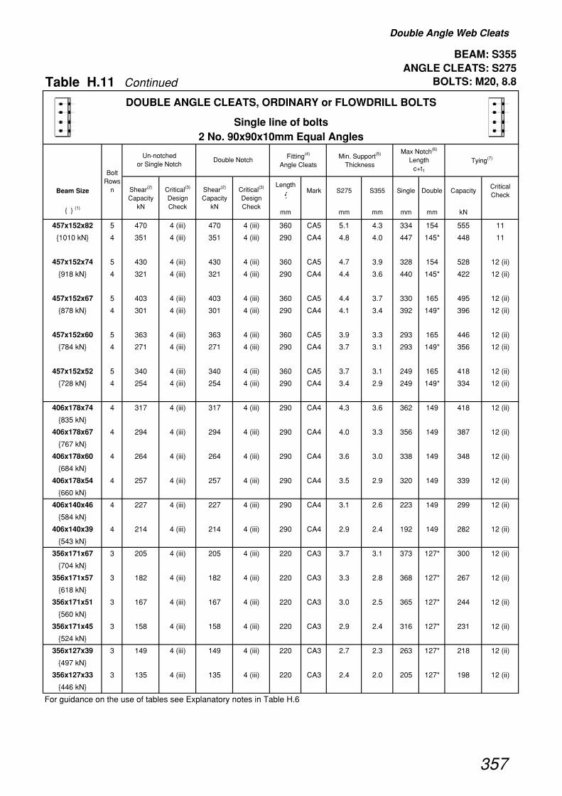
Double Angle Web Cleats
BEAM: S355 ANGLE CLEATS: S275
Table H.11 Continued BOLTS: M20, 8.8
Beam SizeLength
�Mark S275 S355 Single Double Capacity
Critical Check
{ } (1)mm mm mm mm mm kN
Shear(2)
Capacity kN
Double NotchMax Notch(6)
Length c+t1
Critical(3)
Design Check
DOUBLE ANGLE CLEATS, ORDINARY or FLOWDRILL BOLTS
Single line of bolts2 No. 90x90x10mm Equal Angles
Fitting(4)
Angle CleatsMin. Support(5)
ThicknessTying(7)
Bolt Rows
n
Un-notched or Single Notch
Shear(2)
Capacity kN
Critical(3)
Design Check
457x152x82 5 470 4 (iii) 470 4 (iii) 360 CA5 5.1 4.3 334 154 555 11
{1010 kN} 4 351 4 (iii) 351 4 (iii) 290 CA4 4.8 4.0 447 145* 448 11
457x152x74 5 430 4 (iii) 430 4 (iii) 360 CA5 4.7 3.9 328 154 528 12 (ii)
{918 kN} 4 321 4 (iii) 321 4 (iii) 290 CA4 4.4 3.6 440 145* 422 12 (ii)
457x152x67 5 403 4 (iii) 403 4 (iii) 360 CA5 4.4 3.7 330 165 495 12 (ii)
{878 kN} 4 301 4 (iii) 301 4 (iii) 290 CA4 4.1 3.4 392 149* 396 12 (ii)
457x152x60 5 363 4 (iii) 363 4 (iii) 360 CA5 3.9 3.3 293 165 446 12 (ii)
{784 kN} 4 271 4 (iii) 271 4 (iii) 290 CA4 3.7 3.1 293 149* 356 12 (ii)
457x152x52 5 340 4 (iii) 340 4 (iii) 360 CA5 3.7 3.1 249 165 418 12 (ii)
{728 kN} 4 254 4 (iii) 254 4 (iii) 290 CA4 3.4 2.9 249 149* 334 12 (ii)
406x178x74 4 317 4 (iii) 317 4 (iii) 290 CA4 4.3 3.6 362 149 418 12 (ii)
{835 kN}
406x178x67 4 294 4 (iii) 294 4 (iii) 290 CA4 4.0 3.3 356 149 387 12 (ii)
{767 kN}
406x178x60 4 264 4 (iii) 264 4 (iii) 290 CA4 3.6 3.0 338 149 348 12 (ii)
{684 kN}
406x178x54 4 257 4 (iii) 257 4 (iii) 290 CA4 3.5 2.9 320 149 339 12 (ii)
{660 kN}
406x140x46 4 227 4 (iii) 227 4 (iii) 290 CA4 3.1 2.6 223 149 299 12 (ii)
{584 kN}
406x140x39 4 214 4 (iii) 214 4 (iii) 290 CA4 2.9 2.4 192 149 282 12 (ii)
{543 kN}
356x171x67 3 205 4 (iii) 205 4 (iii) 220 CA3 3.7 3.1 373 127* 300 12 (ii)
{704 kN}
356x171x57 3 182 4 (iii) 182 4 (iii) 220 CA3 3.3 2.8 368 127* 267 12 (ii)
{618 kN}
356x171x51 3 167 4 (iii) 167 4 (iii) 220 CA3 3.0 2.5 365 127* 244 12 (ii)
{560 kN}
356x171x45 3 158 4 (iii) 158 4 (iii) 220 CA3 2.9 2.4 316 127* 231 12 (ii)
{524 kN}
356x127x39 3 149 4 (iii) 149 4 (iii) 220 CA3 2.7 2.3 263 127* 218 12 (ii)
{497 kN}
356x127x33 3 135 4 (iii) 135 4 (iii) 220 CA3 2.4 2.0 205 127* 198 12 (ii)
{446 kN}
For guidance on the use of tables see Explanatory notes in Table H.6
357

Double Angle Web Cleats
BEAM: S355 ANGLE CLEATS: S275
Table H.11 Continued BOLTS: M20, 8.8
Beam SizeLength
�Mark S275 S355 Single Double Capacity
Critical Check
{ } (1)mm mm mm mm mm kN
Shear(2)
Capacity kN
Double NotchMax Notch(6)
Length c+t1
Critical(3)
Design Check
DOUBLE ANGLE CLEATS, ORDINARY or FLOWDRILL BOLTS
Single line of bolts2 No. 90x90x10mm Equal Angles
Fitting(4)
Angle CleatsMin. Support(5)
ThicknessTying(7)
Bolt Rows
n
Un-notched or Single Notch
Shear(2)
Capacity kN
Critical(3)
Design Check
305x165x54 3 178 4 (iii) 178 4 (iii) 220 CA3 3.2 2.7 286 127 261 12 (ii)
{522 kN}
305x165x46 3 151 4 (iii) 151 4 (iii) 220 CA3 2.7 2.3 280 127 221 12 (ii)
{438 kN}
305x165x40 3 135 4 (iii) 135 4 (iii) 220 CA3 2.4 2.0 268 127 198 12 (ii)
{388 kN}
305x127x48 3 203 4 (iii) 203 4 (iii) 220 CA3 3.7 3.1 271 127 297 12 (ii)
{596 kN}
305x127x42 3 180 4 (iii) 180 4 (iii) 220 CA3 3.3 2.7 264 127 264 12 (ii)
{523 kN}
305x127x37 3 160 4 (iii) 160 4 (iii) 220 CA3 2.9 2.4 260 127 234 12 (ii)
{460 kN}
305x102x33 3 149 4 (iii) 149 4 (iii) 220 CA3 2.7 2.3 271 127 218 12 (ii)
{440 kN}
305x102x28 3 135 4 (iii) 135 4 (iii) 220 CA3 2.4 2.0 259 127 198 12 (ii)
{395 kN}
305x102x25 3 131 4 (iii) 131 4 (iii) 220 CA3 2.4 2.0 241 127 191 12 (ii)
{377 kN}
254x146x43 2 91 4 (iii) 91 4 (iii) 150 CA2 2.5 2.1 270 106* 158 12 (ii)
{398 kN}
254x146x37 2 79 4 (iii) 79 4 (iii) 150 CA2 2.2 1.8 266 106* 139 12 (ii)
{344 kN}
254x146x31 2 76 4 (iii) 76 4 (iii) 150 CA2 2.1 1.7 261 106* 132 12 (ii)
{321 kN}
254x102x28 2 79 4 (iii) 79 4 (iii) 150 CA2 2.2 1.8 270 106* 139 12 (ii)
{349 kN}
254x102x25 2 76 4 (iii) 76 4 (iii) 150 CA2 2.1 1.7 267 106* 132 12 (ii)
{329 kN}
254x102x22 2 72 4 (iii) 72 4 (iii) 150 CA2 2.0 1.6 264 106* 125 12 (ii)
{308 kN}
For guidance on the use of tables see Explanatory notes in Table H.6
358

Double Angle Web Cleats
BEAM: S355 ANGLE CLEATS: S275
Table H.12 BOLTS: M20, 8.8
Beam SizeLength
�Mark S275 S355 Single Double Capacity
Critical Check
{ } (1)mm mm mm mm mm kN
914x305x253 11 2020 8 2020 8 780 CB11 10.0 8.4 550 132 1200 11
{3290 kN} 10 1840 8 1840 8 710 CB10 10.0 8.4 604 122 1090 11
9 1650 8 1650 8 640 CB9 10.0 8.4 672 113* 984 11
8 1470 8 1470 8 570 CB8 10.0 8.4 685 104* 877 11
914x305x224 11 2020 8 1890 4(ii) 780 CB11 10.0 8.4 468 100 1200 11
{3000 kN} 10 1840 8 1710 4(ii) 710 CB10 10.0 8.4 542 100 1090 11
9 1650 8 1540 4(ii) 640 CB9 10.0 8.4 543 100* 984 11
8 1470 8 1360 4(ii) 570 CB8 10.0 8.4 543 100* 877 11
914x305x201 11 2020 8 1800 4(ii) 780 CB11 10.0 8.4 384 100 1200 11
{2820 kN} 10 1840 8 1630 4(ii) 710 CB10 10.0 8.4 474 100 1090 11
9 1650 8 1460 4(ii) 640 CB9 10.0 8.4 474 100* 984 11
8 1470 8 1290 4(ii) 570 CB8 10.0 8.4 474 100* 877 11
838x292x226 10 1840 8 1740 4(ii) 710 CB10 10.0 8.4 484 100 1090 11
{2840 kN} 9 1650 8 1560 4(ii) 640 CB9 10.0 8.4 537 100 984 11
8 1470 8 1370 4(ii) 570 CB8 10.0 8.4 605 100* 877 11
838x292x194 10 1840 8 1590 4(ii) 710 CB10 10.0 8.4 361 100 1090 11
{2560 kN} 9 1650 8 1420 4(ii) 640 CB9 10.0 8.4 472 100 984 11
8 1470 8 1250 4(ii) 570 CB8 10.0 8.4 504 100* 877 11
838x292x176 10 1840 8 1510 4(ii) 710 CB10 10.0 8.4 287 100 1090 11
{2420 kN} 9 1650 8 1350 4(ii) 640 CB9 10.0 8.4 429 100 984 11
8 1470 8 1190 4(ii) 570 CB8 10.0 8.4 443 100* 877 11
762x267x197 9 1650 8 1510 4(ii) 640 CB9 10.0 8.4 405 100 984 11
{2490 kN} 8 1470 8 1330 4(ii) 570 CB8 10.0 8.4 472 100 877 11
7 1290 8 1150 4(ii) 500 CB7 10.0 8.4 539 100* 769 11
762x267x173 9 1650 8 1380 4(ii) 640 CB9 10.0 8.4 299 100 984 11
{2260 kN} 8 1470 8 1220 4(ii) 570 CB8 10.0 8.4 421 100 877 11
7 1290 8 1060 4(ii) 500 CB7 10.0 8.4 481 100* 769 11
762x267x147 9 1650 8 1240 4(ii) 640 CB9 10.0 8.4 134 100 984 11
{2000 kN} 8 1470 8 1090 4(ii) 570 CB8 10.0 8.4 314 100 877 11
7 1290 8 946 4(ii) 500 CB7 10.0 8.4 416 100* 769 11
762x267x134 9 1600 4(ii) 1190 4(ii) 640 CB9 9.6 8.1 118 100 984 11
{1920 kN} 8 1430 4(ii) 1050 4(ii) 570 CB8 9.7 8.1 297 100 877 11
7 1260 4(ii) 912 4(ii) 500 CB7 9.8 8.2 348 100* 769 11
For guidance on the use of tables see Explanatory notes in Table H.6
Shear(2)
Capacity kN
Double NotchMax Notch(6)
Length c+t1
Critical(3)
Design Check
DOUBLE ANGLE CLEATS, ORDINARY or FLOWDRILL BOLTS
Double line of bolts2 No.150x90x10mm Angles
Fitting(4)
Angle CleatsMin. Support(5)
ThicknessTying(7)
Bolt Rows
n
Un-notched or Single Notch
Shear(2)
Capacity kN
Critical(3)
Design Check
359

Double Angle Web Cleats
BEAM: S355 ANGLE CLEATS: S275
Table H.12 Continued BOLTS: M20, 8.8
Beam SizeLength
�Mark S275 S355 Single Double Capacity
Critical Check
{ } (1)mm mm mm mm mm kN
Shear(2)
Capacity kN
Double NotchMax Notch(6)
Length c+t1
Critical(3)
Design Check
DOUBLE ANGLE CLEATS, ORDINARY or FLOWDRILL BOLTS
Double line of bolts2 No.150x90x10mm Angles
Fitting(4)
Angle CleatsMin. Support(5)
ThicknessTying(7)
Bolt Rows
n
Un-notched or Single Notch
Shear(2)
Capacity kN
Critical(3)
Design Check
686x254x170 8 1470 8 1240 4(ii) 570 CB8 10.0 8.4 305 100 877 11
{2080 kN} 7 1290 8 1070 4(ii) 500 CB7 10.0 8.4 404 100* 769 11
6 1100 8 904 4(ii) 430 CB6 10.0 8.4 471 100* 662 11
686x254x152 8 1470 8 1130 4(ii) 570 CB8 10.0 8.4 198 100 877 11
{1880 kN} 7 1290 8 975 4(ii) 500 CB7 10.0 8.4 353 100 769 11
6 1100 8 823 4(ii) 430 CB6 10.0 8.4 422 100* 662 11
686x254x140 8 1420 4(ii) 1060 4(ii) 570 CB8 9.7 8.1 149 100 877 11
{1750 kN} 7 1260 4(ii) 916 4(ii) 500 CB7 9.7 8.2 312 100 769 11
6 1080 4(ii) 773 4(ii) 430 CB6 9.8 8.2 397 100* 662 11
686x254x125 8 1340 4(ii) 998 4(ii) 570 CB8 9.1 7.6 131 100 877 11
{1640 kN} 7 1180 4(ii) 864 4(ii) 500 CB7 9.2 7.7 298 100 769 11
6 1020 4(ii) 729 4(ii) 430 CB6 9.3 7.7 386 100* 662 11
610x305x238 7 1290 8 1290 8 500 CB7 10.0 8.4 440 141 769 11
{2420 kN} 6 1100 8 1100 8 430 CB6 10.0 8.4 514 124* 662 11
610x305x179 7 1290 8 1040 4(ii) 500 CB7 10.0 8.4 274 100 769 11
{1810 kN} 6 1100 8 879 4(ii) 430 CB6 10.0 8.4 377 100* 662 11
610x305x149 7 1180 4(ii) 872 4(ii) 500 CB7 9.2 7.7 164 100 769 11
{1500 kN} 6 1030 4(ii) 736 4(ii) 430 CB6 9.3 7.8 324 100* 662 11
610x229x140 7 1290 8 968 4(ii) 500 CB7 10.0 8.4 192 100 769 11
{1670 kN} 6 1100 8 817 4(ii) 430 CB6 10.0 8.4 333 100* 662 11
610x229x125 7 1190 4(ii) 879 4(ii) 500 CB7 9.3 7.7 159 100 769 11
{1510 kN} 6 1030 4(ii) 742 4(ii) 430 CB6 9.3 7.8 311 100* 662 11
610x229x113 7 1110 4(ii) 820 4(ii) 500 CB7 8.6 7.2 146 100 769 11
{1400 kN} 6 962 4(ii) 692 4(ii) 430 CB6 8.7 7.3 300 100* 662 11
610x229x101 7 1080 4(ii) 798 4(ii) 500 CB7 8.4 7.0 132 100 769 11
{1350 kN} 6 935 4(ii) 674 4(ii) 430 CB6 8.5 7.1 288 100* 662 11
For guidance on the use of tables see Explanatory notes in Table H.6
360

Double Angle Web Cleats
BEAM: S355 ANGLE CLEATS: S275
Table H.12 Continued BOLTS: M20, 8.8
Beam SizeLength
�Mark S275 S355 Single Double Capacity
Critical Check
{ } (1)mm mm mm mm mm kN
Shear(2)
Capacity kN
Double NotchMax Notch(6)
Length c+t1
Critical(3)
Design Check
DOUBLE ANGLE CLEATS, ORDINARY or FLOWDRILL BOLTS
Double line of bolts2 No.150x90x10mm Angles
Fitting(4)
Angle CleatsMin. Support(5)
ThicknessTying(7)
Bolt Rows
n
Un-notched or Single Notch
Shear(2)
Capacity kN
Critical(3)
Design Check
533x210x122 6 1090 4(ii) 792 4(ii) 430 CB6 9.8 8.2 173 100 662 11
{1430 kN} 5 901 4 (iii) 644 4(ii) 360 CB5 9.8 8.2 302 100* 555 11
533x210x109 6 990 4(ii) 723 4(ii) 430 CB6 9.0 7.5 161 100 662 11
{1300 kN} 5 823 4 (iii) 588 4(ii) 360 CB5 8.9 7.5 296 100* 555 11
533x210x101 6 921 4(ii) 673 4(ii) 430 CB6 8.3 7.0 155 100 662 11
{1200 kN} 5 766 4 (iii) 547 4(ii) 360 CB5 8.3 7.0 293 100* 555 11
533x210x92 6 885 4(ii) 648 4(ii) 430 CB6 8.0 6.7 146 100 662 11
{1150 kN} 5 716 4 (iii) 527 4(ii) 360 CB5 7.8 6.5 296 100* 555 11
533x210x82 6 839 4(ii) 616 4(ii) 430 CB6 7.6 6.4 134 100 662 11
{1080 kN} 5 681 4 (iii) 501 4(ii) 360 CB5 7.4 6.2 287 100* 555 11
457x191x98 5 805 4(ii) 578 4(ii) 360 CB5 8.8 7.3 164 100 555 11
{1100 kN} 4 580 4 (iii) 443 4(ii) 290 CB4 7.9 6.6 303 100* 448 11
457x191x89 5 741 4(ii) 532 4(ii) 360 CB5 8.1 6.7 156 100 555 11
{1010 kN} 4 534 4 (iii) 408 4(ii) 290 CB4 7.3 6.1 298 100* 448 11
457x191x82 5 702 4 (iii) 516 4(ii) 360 CB5 7.6 6.4 163 100 555 11
{970 kN} 4 504 4 (iii) 395 4(ii) 290 CB4 6.8 5.7 301 100* 448 11
457x191x74 5 638 4 (iii) 469 4(ii) 360 CB5 6.9 5.8 156 100 555 11
{876 kN} 4 458 4 (iii) 360 4(ii) 290 CB4 6.2 5.2 298 100* 448 11
457x191x67 5 603 4 (iii) 443 4(ii) 360 CB5 6.6 5.5 146 100 555 11
{821 kN} 4 432 4 (iii) 340 4(ii) 290 CB4 5.9 4.9 290 100* 448 11
For guidance on the use of tables see Explanatory notes in Table H.6
361

Double Angle Web Cleats
BEAM: S355 ANGLE CLEATS: S275
Table H.12 Continued BOLTS: M20, 8.8
Beam SizeLength
�Mark S275 S355 Single Double Capacity
Critical Check
{ } (1)mm mm mm mm mm kN
Shear(2)
Capacity kN
Double NotchMax Notch(6)
Length c+t1
Critical(3)
Design Check
DOUBLE ANGLE CLEATS, ORDINARY or FLOWDRILL BOLTS
Double line of bolts2 No.150x90x10mm Angles
Fitting(4)
Angle CleatsMin. Support(5)
ThicknessTying(7)
Bolt Rows
n
Un-notched or Single Notch
Shear(2)
Capacity kN
Critical(3)
Design Check
457x152x82 5 740 4(ii) 532 4(ii) 360 CB5 8.0 6.7 158 100 555 11
{1010 kN} 4 534 4 (iii) 408 4(ii) 290 CB4 7.3 6.1 294 100* 448 11
457x152x74 5 675 4(ii) 486 4(ii) 360 CB5 7.3 6.1 151 100 555 11
{918 kN} 4 488 4 (iii) 373 4(ii) 290 CB4 6.6 5.5 289 100* 448 11
457x152x67 5 638 4 (iii) 469 4(ii) 360 CB5 6.9 5.8 154 100 555 11
{878 kN} 4 458 4 (iii) 360 4(ii) 290 CB4 6.2 5.2 290 100* 448 11
457x152x60 5 574 4 (iii) 422 4(ii) 360 CB5 6.2 5.2 146 100 555 11
{784 kN} 4 412 4 (iii) 324 4(ii) 290 CB4 5.6 4.7 286 100* 448 11
457x152x52 5 539 4 (iii) 396 4(ii) 360 CB5 5.9 4.9 132 100 555 11
{728 kN} 4 387 4 (iii) 304 4(ii) 290 CB4 5.3 4.4 249 100* 448 11
406x178x74 4 483 4 (iii) 379 4(ii) 290 CB4 6.6 5.5 238 100 448 11
{835 kN}
406x178x67 4 448 4 (iii) 352 4(ii) 290 CB4 6.1 5.1 234 100 448 11
{767 kN}
406x178x60 4 402 4 (iii) 316 4(ii) 290 CB4 5.5 4.6 231 100 448 11
{684 kN}
406x178x54 4 392 4 (iii) 308 4(ii) 290 CB4 5.3 4.5 223 100 448 11
{660 kN}
406x140x46 4 346 4 (iii) 272 4(ii) 290 CB4 4.7 3.9 221 100 448 11
{584 kN}
406x140x39 4 325 4 (iii) 256 4(ii) 290 CB4 4.4 3.7 192 100 448 11
{543 kN}
356x171x67 3 300 4 (iii) 251 4(ii) 220 CB3 5.4 4.5 278 100* 340 11
{704 kN}
356x171x57 3 267 4 (iii) 224 4(ii) 220 CB3 4.8 4.0 268 100* 340 11
{618 kN}
356x171x51 3 244 4 (iii) 204 4(ii) 220 CB3 4.4 3.7 263 100* 340 11
{560 kN}
356x171x45 3 231 4 (iii) 193 4(ii) 220 CB3 4.2 3.5 255 100* 340 11
{524 kN}
356x127x39 3 217 4 (iii) 182 4(ii) 220 CB3 3.9 3.3 251 100* 340 11
{497 kN}
356x127x33 3 198 4 (iii) 166 4(ii) 220 CB3 3.6 3.0 205 100* 340 11
{446 kN}
For guidance on the use of tables see Explanatory notes in Table H.6
362

Double Angle Web Cleats
BEAM: S355 ANGLE CLEATS: S275
Table H.12 Continued BOLTS: M20, 8.8
Beam SizeLength
�Mark S275 S355 Single Double Capacity
Critical Check
{ } (1)mm mm mm mm mm kN
Shear(2)
Capacity kN
Double NotchMax Notch(6)
Length c+t1
Critical(3)
Design Check
DOUBLE ANGLE CLEATS, ORDINARY or FLOWDRILL BOLTS
Double line of bolts2 No.150x90x10mm Angles
Fitting(4)
Angle CleatsMin. Support(5)
ThicknessTying(7)
Bolt Rows
n
Un-notched or Single Notch
Shear(2)
Capacity kN
Critical(3)
Design Check
305x165x54 3 260 4 (iii) 218 4(ii) 220 CB3 4.7 3.9 196 100 340 11
{522 kN}
305x165x46 3 221 4 (iii) 185 4(ii) 220 CB3 4.0 3.3 192 100 340 11
{438 kN}
305x165x40 3 198 4 (iii) 166 4(ii) 220 CB3 3.6 3.0 187 100 340 11
{388 kN}
305x127x48 3 296 4 (iii) 249 4(ii) 220 CB3 5.4 4.5 185 100 340 11
{596 kN}
305x127x42 3 263 4 (iii) 221 4(ii) 220 CB3 4.8 4.0 181 100 340 11
{523 kN}
305x127x37 3 234 4 (iii) 196 4(ii) 220 CB3 4.2 3.5 178 100 340 11
{460 kN}
305x102x33 3 217 4 (iii) 182 4(ii) 220 CB3 3.9 3.3 185 100 340 11
{440 kN}
305x102x28 3 198 4 (iii) 166 4(ii) 220 CB3 3.6 3.0 178 100 340 11
{395 kN}
305x102x25 3 191 4 (iii) 160 4(ii) 220 CB3 3.5 2.9 169 100 340 11
{377 kN}
254x146x43 2 129 4 (iii) 96 4(ii) 150 CB2 3.5 2.9 235 100* 233 11
{398 kN}
254x146x37 2 113 4 (iii) 84 4(ii) 150 CB2 3.1 2.6 229 100* 233 11
{344 kN}
254x146x31 2 107 4 (iii) 80 4(ii) 150 CB2 2.9 2.4 216 100* 233 11
{321 kN}
254x102x28 2 113 4 (iii) 84 4(ii) 150 CB2 3.1 2.6 225 100* 233 11
{349 kN}
254x102x25 2 107 4 (iii) 80 4(ii) 150 CB2 2.9 2.4 215 100* 233 11
{329 kN}
254x102x22 2 102 4 (iii) 76 4(ii) 150 CB2 2.8 2.3 205 100* 233 11
{308 kN}
For guidance on the use of tables see Explanatory notes in Table H.6
363
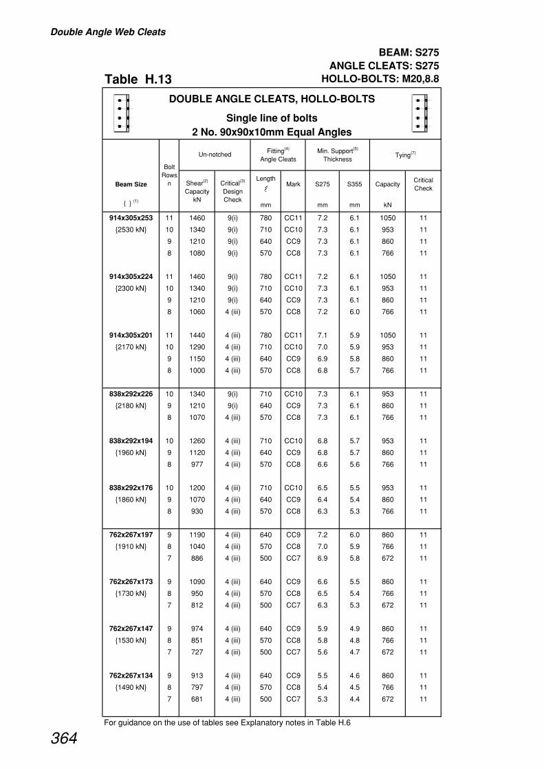
Double Angle Web Cleats
BEAM: S275 ANGLE CLEATS: S275
Table H.13 HOLLO-BOLTS: M20,8.8
Beam SizeLength
�Mark S275 S355 Capacity
Critical Check
{ } (1)mm mm mm kN
914x305x253 11 1460 9(i) 780 CC11 7.2 6.1 1050 11
{2530 kN} 10 1340 9(i) 710 CC10 7.3 6.1 953 11
9 1210 9(i) 640 CC9 7.3 6.1 860 11
8 1080 9(i) 570 CC8 7.3 6.1 766 11
914x305x224 11 1460 9(i) 780 CC11 7.2 6.1 1050 11
{2300 kN} 10 1340 9(i) 710 CC10 7.3 6.1 953 11
9 1210 9(i) 640 CC9 7.3 6.1 860 11
8 1060 4 (iii) 570 CC8 7.2 6.0 766 11
914x305x201 11 1440 4 (iii) 780 CC11 7.1 5.9 1050 11
{2170 kN} 10 1290 4 (iii) 710 CC10 7.0 5.9 953 11
9 1150 4 (iii) 640 CC9 6.9 5.8 860 11
8 1000 4 (iii) 570 CC8 6.8 5.7 766 11
838x292x226 10 1340 9(i) 710 CC10 7.3 6.1 953 11
{2180 kN} 9 1210 9(i) 640 CC9 7.3 6.1 860 11
8 1070 4 (iii) 570 CC8 7.3 6.1 766 11
838x292x194 10 1260 4 (iii) 710 CC10 6.8 5.7 953 11
{1960 kN} 9 1120 4 (iii) 640 CC9 6.8 5.7 860 11
8 977 4 (iii) 570 CC8 6.6 5.6 766 11
838x292x176 10 1200 4 (iii) 710 CC10 6.5 5.5 953 11
{1860 kN} 9 1070 4 (iii) 640 CC9 6.4 5.4 860 11
8 930 4 (iii) 570 CC8 6.3 5.3 766 11
762x267x197 9 1190 4 (iii) 640 CC9 7.2 6.0 860 11
{1910 kN} 8 1040 4 (iii) 570 CC8 7.0 5.9 766 11
7 886 4 (iii) 500 CC7 6.9 5.8 672 11
762x267x173 9 1090 4 (iii) 640 CC9 6.6 5.5 860 11
{1730 kN} 8 950 4 (iii) 570 CC8 6.5 5.4 766 11
7 812 4 (iii) 500 CC7 6.3 5.3 672 11
762x267x147 9 974 4 (iii) 640 CC9 5.9 4.9 860 11
{1530 kN} 8 851 4 (iii) 570 CC8 5.8 4.8 766 11
7 727 4 (iii) 500 CC7 5.6 4.7 672 11
762x267x134 9 913 4 (iii) 640 CC9 5.5 4.6 860 11
{1490 kN} 8 797 4 (iii) 570 CC8 5.4 4.5 766 11
7 681 4 (iii) 500 CC7 5.3 4.4 672 11
For guidance on the use of tables see Explanatory notes in Table H.6
DOUBLE ANGLE CLEATS, HOLLO-BOLTS
Single line of bolts2 No. 90x90x10mm Equal Angles
Fitting(4)
Angle CleatsMin. Support(5)
ThicknessTying(7)
Bolt Rows
n
Un-notched
Shear(2)
Capacity kN
Critical(3)
Design Check
364

Double Angle Web Cleats
BEAM: S275 ANGLE CLEATS: S275
Table H.13 Continued HOLLO-BOLTS: M20,8.8
Beam SizeLength
�Mark S275 S355 Capacity
Critical Check
{ } (1)mm mm mm kN
DOUBLE ANGLE CLEATS, HOLLO-BOLTS
Single line of bolts2 No. 90x90x10mm Equal Angles
Fitting(4)
Angle CleatsMin. Support(5)
ThicknessTying(7)
Bolt Rows
n
Un-notched
Shear(2)
Capacity kN
Critical(3)
Design Check
686x254x170 8 964 4 (iii) 570 CC8 6.5 5.5 766 11
{1600 kN} 7 823 4 (iii) 500 CC7 6.4 5.3 672 11
6 683 4 (iii) 430 CC6 6.2 5.2 580 11
686x254x152 8 877 4 (iii) 570 CC8 6.0 5.0 766 11
{1440 kN} 7 749 4 (iii) 500 CC7 5.8 4.9 672 11
6 621 4 (iii) 430 CC6 5.6 4.7 580 11
686x254x140 8 824 4 (iii) 570 CC8 5.6 4.7 766 11
{1350 kN} 7 704 4 (iii) 500 CC7 5.5 4.6 672 11
6 584 4 (iii) 430 CC6 5.3 4.4 580 11
686x254x125 8 777 4 (iii) 570 CC8 5.3 4.4 766 11
{1260 kN} 7 664 4 (iii) 500 CC7 5.2 4.3 672 11
6 551 4 (iii) 430 CC6 5.0 4.2 580 11
610x305x238 7 947 9(i) 500 CC7 7.4 6.2 672 11
{1860 kN} 6 818 9(i) 430 CC6 7.4 6.2 580 11
610x305x179 7 800 4 (iii) 500 CC7 6.2 5.2 672 11
{1390 kN} 6 664 4 (iii) 430 CC6 6.0 5.0 580 11
610x305x149 7 670 4 (iii) 500 CC7 5.2 4.3 672 11
{1150 kN} 6 556 4 (iii) 430 CC6 5.0 4.2 580 11
610x229x140 7 744 4 (iii) 500 CC7 5.8 4.8 672 11
{1290 kN} 6 617 4 (iii) 430 CC6 5.6 4.7 580 11
610x229x125 7 676 4 (iii) 500 CC7 5.2 4.4 672 11
{1160 kN} 6 560 4 (iii) 430 CC6 5.1 4.2 580 11
610x229x113 7 630 4 (iii) 500 CC7 4.9 4.1 672 11
{1070 kN} 6 523 4 (iii) 430 CC6 4.7 4.0 580 11
610x229x101 7 596 4 (iii) 500 CC7 4.6 3.9 672 11
{1040 kN} 6 494 4 (iii) 430 CC6 4.5 3.7 580 12 (ii)
For guidance on the use of tables see Explanatory notes in Table H.6
365

Double Angle Web Cleats
BEAM: S275 ANGLE CLEATS: S275
Table H.13 Continued HOLLO-BOLTS: M20,8.8
Beam SizeLength
�Mark S275 S355 Capacity
Critical Check
{ } (1)mm mm mm kN
DOUBLE ANGLE CLEATS, HOLLO-BOLTS
Single line of bolts2 No. 90x90x10mm Equal Angles
Fitting(4)
Angle CleatsMin. Support(5)
ThicknessTying(7)
Bolt Rows
n
Un-notched
Shear(2)
Capacity kN
Critical(3)
Design Check
533x210x122 6 598 4 (iii) 430 CC6 5.4 4.5 580 11
{1100 kN} 5 475 4 (iii) 360 CC5 5.2 4.3 486 11
533x210x109 6 546 4 (iii) 430 CC6 4.9 4.1 580 11
{995 kN} 5 434 4 (iii) 360 CC5 4.7 3.9 486 11
533x210x101 6 508 4 (iii) 430 CC6 4.6 3.9 580 11
{922 kN} 5 404 4 (iii) 360 CC5 4.4 3.7 486 11
533x210x92 6 475 4 (iii) 430 CC6 4.3 3.6 558 12 (ii)
{888 kN} 5 378 4 (iii) 360 CC5 4.1 3.4 465 12 (ii)
533x210x82 6 452 4 (iii) 430 CC6 4.1 3.4 530 12 (ii)
{837 kN} 5 359 4 (iii) 360 CC5 3.9 3.3 442 12 (ii)
457x191x98 5 427 4 (iii) 360 CC5 4.6 3.9 486 11
{847 kN} 4 319 4 (iii) 290 CC4 4.3 3.6 393 11
457x191x89 5 393 4 (iii) 360 CC5 4.3 3.6 483 12 (ii)
{774 kN} 4 293 4 (iii) 290 CC4 4.0 3.3 386 12 (ii)
457x191x82 5 371 4 (iii) 360 CC5 4.0 3.4 455 12 (ii)
{751 kN} 4 277 4 (iii) 290 CC4 3.8 3.1 364 12 (ii)
457x191x74 5 337 4 (iii) 360 CC5 3.7 3.1 414 12 (ii)
{679 kN} 4 251 4 (iii) 290 CC4 3.4 2.9 331 12 (ii)
457x191x67 5 318 4 (iii) 360 CC5 3.5 2.9 391 12 (ii)
{636 kN} 4 237 4 (iii) 290 CC4 3.2 2.7 313 12 (ii)
For guidance on the use of tables see Explanatory notes in Table H.6
366

Double Angle Web Cleats
BEAM: S275 ANGLE CLEATS: S275
Table H.13 Continued HOLLO-BOLTS: M20,8.8
Beam SizeLength
�Mark S275 S355 Capacity
Critical Check
{ } (1)mm mm mm kN
DOUBLE ANGLE CLEATS, HOLLO-BOLTS
Single line of bolts2 No. 90x90x10mm Equal Angles
Fitting(4)
Angle CleatsMin. Support(5)
ThicknessTying(7)
Bolt Rows
n
Un-notched
Shear(2)
Capacity kN
Critical(3)
Design Check
457x152x82 5 393 4 (iii) 360 CC5 4.3 3.6 483 12 (ii)
{778 kN} 4 293 4 (iii) 290 CC4 4.0 3.3 386 12 (ii)
457x152x74 5 359 4 (iii) 360 CC5 3.9 3.3 442 12 (ii)
{705 kN} 4 268 4 (iii) 290 CC4 3.6 3.0 353 12 (ii)
457x152x67 5 337 4 (iii) 360 CC5 3.7 3.1 414 12 (ii)
{680 kN} 4 251 4 (iii) 290 CC4 3.4 2.9 331 12 (ii)
457x152x60 5 303 4 (iii) 360 CC5 3.3 2.8 373 12 (ii)
{608 kN} 4 226 4 (iii) 290 CC4 3.1 2.6 298 12 (ii)
457x152x52 5 284 4 (iii) 360 CC5 3.1 2.6 350 12 (ii)
{564 kN} 4 212 4 (iii) 290 CC4 2.9 2.4 280 12 (ii)
406x178x74 4 265 4 (iii) 290 CC4 3.6 3.0 350 12 (ii)
{647 kN}
406x178x67 4 246 4 (iii) 290 CC4 3.3 2.8 324 12 (ii)
{594 kN}
406x178x60 4 221 4 (iii) 290 CC4 3.0 2.5 291 12 (ii)
{530 kN}
406x178x54 4 215 4 (iii) 290 CC4 2.9 2.4 283 12 (ii)
{512 kN}
406x140x46 4 190 4 (iii) 290 CC4 2.6 2.2 250 12 (ii)
{452 kN}
406x140x39 4 179 4 (iii) 290 CC4 2.4 2.0 236 12 (ii)
{420 kN}
356x171x67 3 171 4 (iii) 220 CC3 3.1 2.6 251 12 (ii)
{546 kN}
356x171x57 3 153 4 (iii) 220 CC3 2.8 2.3 224 12 (ii)
{478 kN}
356x171x51 3 139 4 (iii) 220 CC3 2.5 2.1 204 12 (ii)
{433 kN}
356x171x45 3 132 4 (iii) 220 CC3 2.4 2.0 193 12 (ii)
{406 kN}
356x127x39 3 124 4 (iii) 220 CC3 2.3 1.9 182 12 (ii)
{385 kN}
356x127x33 3 113 4 (iii) 220 CC3 2.0 1.7 166 12 (ii)
{346 kN}
For guidance on the use of tables see Explanatory notes in Table H.6
367

Double Angle Web Cleats
BEAM: S275 ANGLE CLEATS: S275
Table H.13 Continued HOLLO-BOLTS: M20,8.8
Beam SizeLength
�Mark S275 S355 Capacity
Critical Check
{ } (1)mm mm mm kN
DOUBLE ANGLE CLEATS, HOLLO-BOLTS
Single line of bolts2 No. 90x90x10mm Equal Angles
Fitting(4)
Angle CleatsMin. Support(5)
ThicknessTying(7)
Bolt Rows
n
Un-notched
Shear(2)
Capacity kN
Critical(3)
Design Check
305x165x54 3 149 4 (iii) 220 CC3 2.7 2.3 218 12 (ii)
{405 kN}
305x165x46 3 126 4 (iii) 220 CC3 2.3 1.9 185 12 (ii)
{339 kN}
305x165x40 3 113 4 (iii) 220 CC3 2.0 1.7 166 12 (ii)
{300 kN}
305x127x48 3 169 4 (iii) 220 CC3 3.1 2.6 248 12 (ii)
{462 kN}
305x127x42 3 151 4 (iii) 220 CC3 2.7 2.3 221 12 (ii)
{406 kN}
305x127x37 3 134 4 (iii) 220 CC3 2.4 2.0 196 12 (ii)
{357 kN}
305x102x33 3 124 4 (iii) 220 CC3 2.3 1.9 182 12 (ii)
{341 kN}
305x102x28 3 113 4 (iii) 220 CC3 2.0 1.7 166 12 (ii)
{306 kN}
305x102x25 3 109 4 (iii) 220 CC3 2.0 1.7 160 12 (ii)
{292 kN}
254x146x43 2 76 4 (iii) 150 CC2 2.1 1.7 132 12 (ii)
{308 kN}
254x146x37 2 66 4 (iii) 150 CC2 1.8 1.5 116 12 (ii)
{266 kN}
254x146x31 2 63 4 (iii) 150 CC2 1.7 1.4 110 12 (ii)
{249 kN}
254x102x28 2 66 4 (iii) 150 CC2 1.8 1.5 116 12 (ii)
{271 kN}
254x102x25 2 63 4 (iii) 150 CC2 1.7 1.4 110 12 (ii)
{255 kN}
254x102x22 2 60 4 (iii) 150 CC2 1.6 1.4 105 12 (ii)
{239 kN}
For guidance on the use of tables see Explanatory notes in Table H.6
368

Double Angle Web Cleats
BEAM: S275 ANGLE CLEATS: S275
Table H.14 HOLLO-BOLTS: M20,8.8
Beam SizeLength
�Mark S275 S355 Capacity
Critical Check
{ } (1)mm mm mm kN
914x305x253 11 1460 9(i) 780 CD11 7.2 6.1 1050 11
{2530 kN} 10 1340 9(i) 710 CD10 7.3 6.1 953 11
9 1210 9(i) 640 CD9 7.3 6.1 860 11
8 1080 9(i) 570 CD8 7.3 6.1 766 11
914x305x224 11 1460 9(i) 780 CD11 7.2 6.1 1050 11
{2300 kN} 10 1340 9(i) 710 CD10 7.3 6.1 953 11
9 1210 9(i) 640 CD9 7.3 6.1 860 11
8 1080 9(i) 570 CD8 7.3 6.1 766 11
914x305x201 11 1460 9(i) 780 CD11 7.2 6.1 1050 11
{2170 kN} 10 1340 9(i) 710 CD10 7.3 6.1 953 11
9 1210 9(i) 640 CD9 7.3 6.1 860 11
8 1080 9(i) 570 CD8 7.3 6.1 766 11
838x292x226 10 1340 9(i) 710 CD10 7.3 6.1 953 11
{2180 kN} 9 1210 9(i) 640 CD9 7.3 6.1 860 11
8 1080 9(i) 570 CD8 7.3 6.1 766 11
838x292x194 10 1340 9(i) 710 CD10 7.3 6.1 953 11
{1960 kN} 9 1210 9(i) 640 CD9 7.3 6.1 860 11
8 1080 9(i) 570 CD8 7.3 6.1 766 11
838x292x176 10 1340 9(i) 710 CD10 7.3 6.1 953 11
{1860 kN} 9 1210 9(i) 640 CD9 7.3 6.1 860 11
8 1080 9(i) 570 CD8 7.3 6.1 766 11
762x267x197 9 1210 9(i) 640 CD9 7.3 6.1 860 11
{1910 kN} 8 1080 9(i) 570 CD8 7.3 6.1 766 11
7 947 9(i) 500 CD7 7.4 6.2 672 11
762x267x173 9 1210 9(i) 640 CD9 7.3 6.1 860 11
{1730 kN} 8 1080 9(i) 570 CD8 7.3 6.1 766 11
7 947 9(i) 500 CD7 7.4 6.2 672 11
762x267x147 9 1210 9(i) 640 CD9 7.3 6.1 860 11
{1530 kN} 8 1080 9(i) 570 CD8 7.3 6.1 766 11
7 947 9(i) 500 CD7 7.4 6.2 672 11
762x267x134 9 1210 9(i) 640 CD9 7.3 6.1 860 11
{1490 kN} 8 1080 9(i) 570 CD8 7.3 6.1 766 11
7 947 9(i) 500 CD7 7.4 6.2 672 11
For guidance on the use of tables see Explanatory notes in Table H.6
DOUBLE ANGLE CLEATS, HOLLO-BOLTS
Double line of bolts2 No.150x90x10mm Angles
Fitting(4)
Angle CleatsMin. Support(5)
ThicknessTying(7)
Bolt Rows
n
Un-notched
Shear(2)
Capacity kN
Critical(3)
Design Check
369
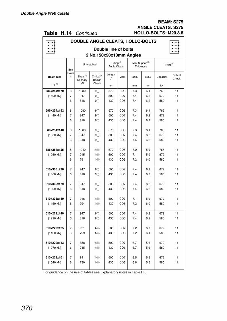
Double Angle Web Cleats
BEAM: S275 ANGLE CLEATS: S275
Table H.14 Continued HOLLO-BOLTS: M20,8.8
Beam SizeLength
�Mark S275 S355 Capacity
Critical Check
{ } (1)mm mm mm kN
DOUBLE ANGLE CLEATS, HOLLO-BOLTS
Double line of bolts2 No.150x90x10mm Angles
Fitting(4)
Angle CleatsMin. Support(5)
ThicknessTying(7)
Bolt Rows
n
Un-notched
Shear(2)
Capacity kN
Critical(3)
Design Check
686x254x170 8 1080 9(i) 570 CD8 7.3 6.1 766 11
{1600 kN} 7 947 9(i) 500 CD7 7.4 6.2 672 11
6 818 9(i) 430 CD6 7.4 6.2 580 11
686x254x152 8 1080 9(i) 570 CD8 7.3 6.1 766 11
{1440 kN} 7 947 9(i) 500 CD7 7.4 6.2 672 11
6 818 9(i) 430 CD6 7.4 6.2 580 11
686x254x140 8 1080 9(i) 570 CD8 7.3 6.1 766 11
{1350 kN} 7 947 9(i) 500 CD7 7.4 6.2 672 11
6 818 9(i) 430 CD6 7.4 6.2 580 11
686x254x125 8 1040 4(ii) 570 CD8 7.0 5.9 766 11
{1260 kN} 7 915 4(ii) 500 CD7 7.1 5.9 672 11
6 791 4(ii) 430 CD6 7.2 6.0 580 11
610x305x238 7 947 9(i) 500 CD7 7.4 6.2 672 11
{1860 kN} 6 818 9(i) 430 CD6 7.4 6.2 580 11
610x305x179 7 947 9(i) 500 CD7 7.4 6.2 672 11
{1390 kN} 6 818 9(i) 430 CD6 7.4 6.2 580 11
610x305x149 7 916 4(ii) 500 CD7 7.1 5.9 672 11
{1150 kN} 6 794 4(ii) 430 CD6 7.2 6.0 580 11
610x229x140 7 947 9(i) 500 CD7 7.4 6.2 672 11
{1290 kN} 6 818 9(i) 430 CD6 7.4 6.2 580 11
610x229x125 7 921 4(ii) 500 CD7 7.2 6.0 672 11
{1160 kN} 6 799 4(ii) 430 CD6 7.2 6.1 580 11
610x229x113 7 858 4(ii) 500 CD7 6.7 5.6 672 11
{1070 kN} 6 745 4(ii) 430 CD6 6.7 5.6 580 11
610x229x101 7 841 4(ii) 500 CD7 6.5 5.5 672 11
{1040 kN} 6 730 4(ii) 430 CD6 6.6 5.5 580 11
For guidance on the use of tables see Explanatory notes in Table H.6
370

Double Angle Web Cleats
BEAM: S275 ANGLE CLEATS: S275
Table H.14 Continued HOLLO-BOLTS: M20,8.8
Beam SizeLength
�Mark S275 S355 Capacity
Critical Check
{ } (1)mm mm mm kN
DOUBLE ANGLE CLEATS, HOLLO-BOLTS
Double line of bolts2 No.150x90x10mm Angles
Fitting(4)
Angle CleatsMin. Support(5)
ThicknessTying(7)
Bolt Rows
n
Un-notched
Shear(2)
Capacity kN
Critical(3)
Design Check
533x210x122 6 818 9(i) 430 CD6 7.4 6.2 580 11
{1100 kN} 5 688 9(i) 360 CD5 7.5 6.3 486 11
533x210x109 6 766 4(ii) 430 CD6 6.9 5.8 580 11
{995 kN} 5 649 4(ii) 360 CD5 7.1 5.9 486 11
533x210x101 6 713 4(ii) 430 CD6 6.5 5.4 580 11
{922 kN} 5 604 4(ii) 360 CD5 6.6 5.5 486 11
533x210x92 6 691 4(ii) 430 CD6 6.3 5.2 580 11
{888 kN} 5 586 4(ii) 360 CD5 6.4 5.3 486 11
533x210x82 6 655 4(ii) 430 CD6 5.9 5.0 580 11
{837 kN} 5 556 4(ii) 360 CD5 6.0 5.1 486 11
457x191x98 5 624 4(ii) 360 CD5 6.8 5.7 486 11
{847 kN} 4 485 4 (iii) 290 CD4 6.6 5.5 393 11
457x191x89 5 574 4(ii) 360 CD5 6.2 5.2 486 11
{774 kN} 4 447 4 (iii) 290 CD4 6.1 5.1 393 11
457x191x82 5 561 4(ii) 360 CD5 6.1 5.1 486 11
{751 kN} 4 421 4 (iii) 290 CD4 5.7 4.8 393 11
457x191x74 5 509 4(ii) 360 CD5 5.5 4.6 486 11
{679 kN} 4 383 4 (iii) 290 CD4 5.2 4.4 393 11
457x191x67 5 480 4(ii) 360 CD5 5.2 4.4 486 11
{636 kN} 4 362 4 (iii) 290 CD4 4.9 4.1 393 11
For guidance on the use of tables see Explanatory notes in Table H.6
371
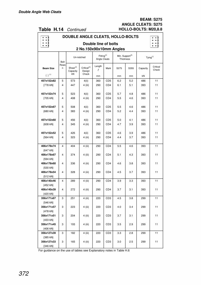
Double Angle Web Cleats
BEAM: S275 ANGLE CLEATS: S275
Table H.14 Continued HOLLO-BOLTS: M20,8.8
Beam SizeLength
�Mark S275 S355 Capacity
Critical Check
{ } (1)mm mm mm kN
DOUBLE ANGLE CLEATS, HOLLO-BOLTS
Double line of bolts2 No.150x90x10mm Angles
Fitting(4)
Angle CleatsMin. Support(5)
ThicknessTying(7)
Bolt Rows
n
Un-notched
Shear(2)
Capacity kN
Critical(3)
Design Check
457x152x82 5 573 4(ii) 360 CD5 6.2 5.2 486 11
{778 kN} 4 447 4 (iii) 290 CD4 6.1 5.1 393 11
457x152x74 5 523 4(ii) 360 CD5 5.7 4.8 486 11
{705 kN} 4 408 4 (iii) 290 CD4 5.5 4.6 393 11
457x152x67 5 508 4(ii) 360 CD5 5.5 4.6 486 11
{680 kN} 4 383 4 (iii) 290 CD4 5.2 4.4 393 11
457x152x60 5 456 4(ii) 360 CD5 5.0 4.1 486 11
{608 kN} 4 345 4 (iii) 290 CD4 4.7 3.9 393 11
457x152x52 5 426 4(ii) 360 CD5 4.6 3.9 486 11
{564 kN} 4 323 4 (iii) 290 CD4 4.4 3.7 393 11
406x178x74 4 404 4 (iii) 290 CD4 5.5 4.6 393 11
{647 kN}
406x178x67 4 374 4 (iii) 290 CD4 5.1 4.3 393 11
{594 kN}
406x178x60 4 336 4 (iii) 290 CD4 4.6 3.8 393 11
{530 kN}
406x178x54 4 328 4 (iii) 290 CD4 4.5 3.7 393 11
{512 kN}
406x140x46 4 289 4 (iii) 290 CD4 3.9 3.3 393 11
{452 kN}
406x140x39 4 272 4 (iii) 290 CD4 3.7 3.1 393 11
{420 kN}
356x171x67 3 251 4 (iii) 220 CD3 4.5 3.8 299 11
{546 kN}
356x171x57 3 223 4 (iii) 220 CD3 4.0 3.4 299 11
{478 kN}
356x171x51 3 204 4 (iii) 220 CD3 3.7 3.1 299 11
{433 kN}
356x171x45 3 193 4 (iii) 220 CD3 3.5 2.9 299 11
{406 kN}
356x127x39 3 182 4 (iii) 220 CD3 3.3 2.8 299 11
{385 kN}
356x127x33 3 165 4 (iii) 220 CD3 3.0 2.5 299 11
{346 kN}
For guidance on the use of tables see Explanatory notes in Table H.6
372

Double Angle Web Cleats
BEAM: S275 ANGLE CLEATS: S275
Table H.14 Continued HOLLO-BOLTS: M20,8.8
Beam SizeLength
�Mark S275 S355 Capacity
Critical Check
{ } (1)mm mm mm kN
DOUBLE ANGLE CLEATS, HOLLO-BOLTS
Double line of bolts2 No.150x90x10mm Angles
Fitting(4)
Angle CleatsMin. Support(5)
ThicknessTying(7)
Bolt Rows
n
Un-notched
Shear(2)
Capacity kN
Critical(3)
Design Check
305x165x54 3 218 4 (iii) 220 CD3 3.9 3.3 299 11
{405 kN}
305x165x46 3 185 4 (iii) 220 CD3 3.3 2.8 299 11
{339 kN}
305x165x40 3 165 4 (iii) 220 CD3 3.0 2.5 299 11
{300 kN}
305x127x48 3 248 4 (iii) 220 CD3 4.5 3.8 299 11
{462 kN}
305x127x42 3 220 4 (iii) 220 CD3 4.0 3.3 299 11
{406 kN}
305x127x37 3 196 4 (iii) 220 CD3 3.5 3.0 299 11
{357 kN}
305x102x33 3 182 4 (iii) 220 CD3 3.3 2.8 299 11
{341 kN}
305x102x28 3 165 4 (iii) 220 CD3 3.0 2.5 299 11
{306 kN}
305x102x25 3 160 4 (iii) 220 CD3 2.9 2.4 299 11
{292 kN}
254x146x43 2 108 4 (iii) 150 CD2 2.9 2.4 206 11
{308 kN}
254x146x37 2 94 4 (iii) 150 CD2 2.6 2.1 206 11
{266 kN}
254x146x31 2 90 4 (iii) 150 CD2 2.4 2.0 206 11
{249 kN}
254x102x28 2 94 4 (iii) 150 CD2 2.6 2.1 206 11
{271 kN}
254x102x25 2 90 4 (iii) 150 CD2 2.4 2.0 206 11
{255 kN}
254x102x22 2 85 4 (iii) 150 CD2 2.3 1.9 206 11
{239 kN}
For guidance on the use of tables see Explanatory notes in Table H.6
373
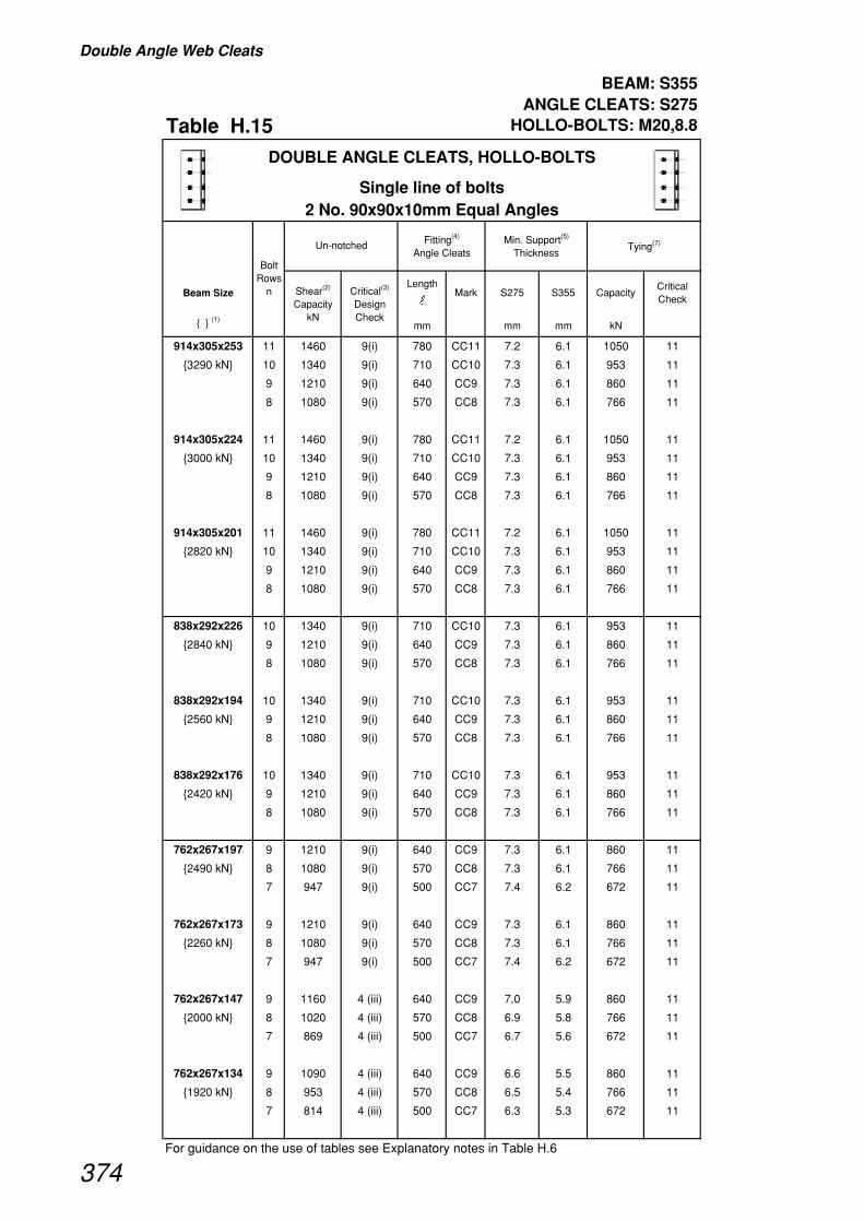
Double Angle Web Cleats
BEAM: S355 ANGLE CLEATS: S275
Table H.15 HOLLO-BOLTS: M20,8.8
Beam SizeLength
�Mark S275 S355 Capacity
Critical Check
{ } (1)mm mm mm kN
914x305x253 11 1460 9(i) 780 CC11 7.2 6.1 1050 11
{3290 kN} 10 1340 9(i) 710 CC10 7.3 6.1 953 11
9 1210 9(i) 640 CC9 7.3 6.1 860 11
8 1080 9(i) 570 CC8 7.3 6.1 766 11
914x305x224 11 1460 9(i) 780 CC11 7.2 6.1 1050 11
{3000 kN} 10 1340 9(i) 710 CC10 7.3 6.1 953 11
9 1210 9(i) 640 CC9 7.3 6.1 860 11
8 1080 9(i) 570 CC8 7.3 6.1 766 11
914x305x201 11 1460 9(i) 780 CC11 7.2 6.1 1050 11
{2820 kN} 10 1340 9(i) 710 CC10 7.3 6.1 953 11
9 1210 9(i) 640 CC9 7.3 6.1 860 11
8 1080 9(i) 570 CC8 7.3 6.1 766 11
838x292x226 10 1340 9(i) 710 CC10 7.3 6.1 953 11
{2840 kN} 9 1210 9(i) 640 CC9 7.3 6.1 860 11
8 1080 9(i) 570 CC8 7.3 6.1 766 11
838x292x194 10 1340 9(i) 710 CC10 7.3 6.1 953 11
{2560 kN} 9 1210 9(i) 640 CC9 7.3 6.1 860 11
8 1080 9(i) 570 CC8 7.3 6.1 766 11
838x292x176 10 1340 9(i) 710 CC10 7.3 6.1 953 11
{2420 kN} 9 1210 9(i) 640 CC9 7.3 6.1 860 11
8 1080 9(i) 570 CC8 7.3 6.1 766 11
762x267x197 9 1210 9(i) 640 CC9 7.3 6.1 860 11
{2490 kN} 8 1080 9(i) 570 CC8 7.3 6.1 766 11
7 947 9(i) 500 CC7 7.4 6.2 672 11
762x267x173 9 1210 9(i) 640 CC9 7.3 6.1 860 11
{2260 kN} 8 1080 9(i) 570 CC8 7.3 6.1 766 11
7 947 9(i) 500 CC7 7.4 6.2 672 11
762x267x147 9 1160 4 (iii) 640 CC9 7.0 5.9 860 11
{2000 kN} 8 1020 4 (iii) 570 CC8 6.9 5.8 766 11
7 869 4 (iii) 500 CC7 6.7 5.6 672 11
762x267x134 9 1090 4 (iii) 640 CC9 6.6 5.5 860 11
{1920 kN} 8 953 4 (iii) 570 CC8 6.5 5.4 766 11
7 814 4 (iii) 500 CC7 6.3 5.3 672 11
For guidance on the use of tables see Explanatory notes in Table H.6
DOUBLE ANGLE CLEATS, HOLLO-BOLTS
Single line of bolts2 No. 90x90x10mm Equal Angles
Fitting(4)
Angle CleatsMin. Support(5)
ThicknessTying(7)
Bolt Rows
n
Un-notched
Shear(2)
Capacity kN
Critical(3)
Design Check
374
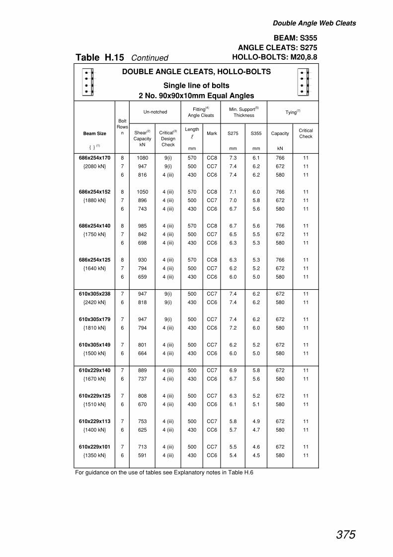
Double Angle Web Cleats
BEAM: S355 ANGLE CLEATS: S275
Table H.15 Continued HOLLO-BOLTS: M20,8.8
Beam SizeLength
�Mark S275 S355 Capacity
Critical Check
{ } (1)mm mm mm kN
DOUBLE ANGLE CLEATS, HOLLO-BOLTS
Single line of bolts2 No. 90x90x10mm Equal Angles
Fitting(4)
Angle CleatsMin. Support(5)
ThicknessTying(7)
Bolt Rows
n
Un-notched
Shear(2)
Capacity kN
Critical(3)
Design Check
686x254x170 8 1080 9(i) 570 CC8 7.3 6.1 766 11
{2080 kN} 7 947 9(i) 500 CC7 7.4 6.2 672 11
6 816 4 (iii) 430 CC6 7.4 6.2 580 11
686x254x152 8 1050 4 (iii) 570 CC8 7.1 6.0 766 11
{1880 kN} 7 896 4 (iii) 500 CC7 7.0 5.8 672 11
6 743 4 (iii) 430 CC6 6.7 5.6 580 11
686x254x140 8 985 4 (iii) 570 CC8 6.7 5.6 766 11
{1750 kN} 7 842 4 (iii) 500 CC7 6.5 5.5 672 11
6 698 4 (iii) 430 CC6 6.3 5.3 580 11
686x254x125 8 930 4 (iii) 570 CC8 6.3 5.3 766 11
{1640 kN} 7 794 4 (iii) 500 CC7 6.2 5.2 672 11
6 659 4 (iii) 430 CC6 6.0 5.0 580 11
610x305x238 7 947 9(i) 500 CC7 7.4 6.2 672 11
{2420 kN} 6 818 9(i) 430 CC6 7.4 6.2 580 11
610x305x179 7 947 9(i) 500 CC7 7.4 6.2 672 11
{1810 kN} 6 794 4 (iii) 430 CC6 7.2 6.0 580 11
610x305x149 7 801 4 (iii) 500 CC7 6.2 5.2 672 11
{1500 kN} 6 664 4 (iii) 430 CC6 6.0 5.0 580 11
610x229x140 7 889 4 (iii) 500 CC7 6.9 5.8 672 11
{1670 kN} 6 737 4 (iii) 430 CC6 6.7 5.6 580 11
610x229x125 7 808 4 (iii) 500 CC7 6.3 5.2 672 11
{1510 kN} 6 670 4 (iii) 430 CC6 6.1 5.1 580 11
610x229x113 7 753 4 (iii) 500 CC7 5.8 4.9 672 11
{1400 kN} 6 625 4 (iii) 430 CC6 5.7 4.7 580 11
610x229x101 7 713 4 (iii) 500 CC7 5.5 4.6 672 11
{1350 kN} 6 591 4 (iii) 430 CC6 5.4 4.5 580 11
For guidance on the use of tables see Explanatory notes in Table H.6
375

Double Angle Web Cleats
BEAM: S355 ANGLE CLEATS: S275
Table H.15 Continued HOLLO-BOLTS: M20,8.8
Beam SizeLength
�Mark S275 S355 Capacity
Critical Check
{ } (1)mm mm mm kN
DOUBLE ANGLE CLEATS, HOLLO-BOLTS
Single line of bolts2 No. 90x90x10mm Equal Angles
Fitting(4)
Angle CleatsMin. Support(5)
ThicknessTying(7)
Bolt Rows
n
Un-notched
Shear(2)
Capacity kN
Critical(3)
Design Check
533x210x122 6 715 4 (iii) 430 CC6 6.5 5.4 580 11
{1430 kN} 5 568 4 (iii) 360 CC5 6.2 5.2 486 11
533x210x109 6 653 4 (iii) 430 CC6 5.9 4.9 580 11
{1300 kN} 5 519 4 (iii) 360 CC5 5.6 4.7 486 11
533x210x101 6 608 4 (iii) 430 CC6 5.5 4.6 580 11
{1200 kN} 5 483 4 (iii) 360 CC5 5.3 4.4 486 11
533x210x92 6 569 4 (iii) 430 CC6 5.1 4.3 580 11
{1150 kN} 5 452 4 (iii) 360 CC5 4.9 4.1 486 11
533x210x82 6 540 4 (iii) 430 CC6 4.9 4.1 580 11
{1080 kN} 5 430 4 (iii) 360 CC5 4.7 3.9 486 11
457x191x98 5 510 4 (iii) 360 CC5 5.5 4.6 486 11
{1100 kN} 4 381 4 (iii) 290 CC4 5.2 4.3 393 11
457x191x89 5 470 4 (iii) 360 CC5 5.1 4.3 486 11
{1010 kN} 4 351 4 (iii) 290 CC4 4.8 4.0 393 11
457x191x82 5 443 4 (iii) 360 CC5 4.8 4.0 486 11
{970 kN} 4 331 4 (iii) 290 CC4 4.5 3.8 393 11
457x191x74 5 403 4 (iii) 360 CC5 4.4 3.7 486 11
{876 kN} 4 301 4 (iii) 290 CC4 4.1 3.4 393 11
457x191x67 5 380 4 (iii) 360 CC5 4.1 3.5 468 12 (ii)
{821 kN} 4 284 4 (iii) 290 CC4 3.9 3.2 374 12 (ii)
For guidance on the use of tables see Explanatory notes in Table H.6
376
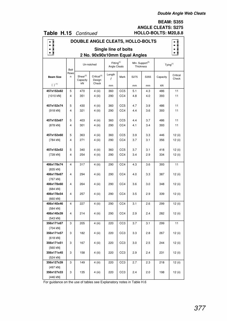
Double Angle Web Cleats
BEAM: S355 ANGLE CLEATS: S275
Table H.15 Continued HOLLO-BOLTS: M20,8.8
Beam SizeLength
�Mark S275 S355 Capacity
Critical Check
{ } (1)mm mm mm kN
DOUBLE ANGLE CLEATS, HOLLO-BOLTS
Single line of bolts2 No. 90x90x10mm Equal Angles
Fitting(4)
Angle CleatsMin. Support(5)
ThicknessTying(7)
Bolt Rows
n
Un-notched
Shear(2)
Capacity kN
Critical(3)
Design Check
457x152x82 5 470 4 (iii) 360 CC5 5.1 4.3 486 11
{1010 kN} 4 351 4 (iii) 290 CC4 4.8 4.0 393 11
457x152x74 5 430 4 (iii) 360 CC5 4.7 3.9 486 11
{918 kN} 4 321 4 (iii) 290 CC4 4.4 3.6 393 11
457x152x67 5 403 4 (iii) 360 CC5 4.4 3.7 486 11
{878 kN} 4 301 4 (iii) 290 CC4 4.1 3.4 393 11
457x152x60 5 363 4 (iii) 360 CC5 3.9 3.3 446 12 (ii)
{784 kN} 4 271 4 (iii) 290 CC4 3.7 3.1 356 12 (ii)
457x152x52 5 340 4 (iii) 360 CC5 3.7 3.1 418 12 (ii)
{728 kN} 4 254 4 (iii) 290 CC4 3.4 2.9 334 12 (ii)
406x178x74 4 317 4 (iii) 290 CC4 4.3 3.6 393 11
{835 kN}
406x178x67 4 294 4 (iii) 290 CC4 4.0 3.3 387 12 (ii)
{767 kN}
406x178x60 4 264 4 (iii) 290 CC4 3.6 3.0 348 12 (ii)
{684 kN}
406x178x54 4 257 4 (iii) 290 CC4 3.5 2.9 339 12 (ii)
{660 kN}
406x140x46 4 227 4 (iii) 290 CC4 3.1 2.6 299 12 (ii)
{584 kN}
406x140x39 4 214 4 (iii) 290 CC4 2.9 2.4 282 12 (ii)
{543 kN}
356x171x67 3 205 4 (iii) 220 CC3 3.7 3.1 299 11
{704 kN}
356x171x57 3 182 4 (iii) 220 CC3 3.3 2.8 267 12 (ii)
{618 kN}
356x171x51 3 167 4 (iii) 220 CC3 3.0 2.5 244 12 (ii)
{560 kN}
356x171x45 3 158 4 (iii) 220 CC3 2.9 2.4 231 12 (ii)
{524 kN}
356x127x39 3 149 4 (iii) 220 CC3 2.7 2.3 218 12 (ii)
{497 kN}
356x127x33 3 135 4 (iii) 220 CC3 2.4 2.0 198 12 (ii)
{446 kN}
For guidance on the use of tables see Explanatory notes in Table H.6
377

Double Angle Web Cleats
BEAM: S355 ANGLE CLEATS: S275
Table H.15 Continued HOLLO-BOLTS: M20,8.8
Beam SizeLength
�Mark S275 S355 Capacity
Critical Check
{ } (1)mm mm mm kN
DOUBLE ANGLE CLEATS, HOLLO-BOLTS
Single line of bolts2 No. 90x90x10mm Equal Angles
Fitting(4)
Angle CleatsMin. Support(5)
ThicknessTying(7)
Bolt Rows
n
Un-notched
Shear(2)
Capacity kN
Critical(3)
Design Check
305x165x54 3 178 4 (iii) 220 CC3 3.2 2.7 261 12 (ii)
{522 kN}
305x165x46 3 151 4 (iii) 220 CC3 2.7 2.3 221 12 (ii)
{438 kN}
305x165x40 3 135 4 (iii) 220 CC3 2.4 2.0 198 12 (ii)
{388 kN}
305x127x48 3 203 4 (iii) 220 CC3 3.7 3.1 297 12 (ii)
{596 kN}
305x127x42 3 180 4 (iii) 220 CC3 3.3 2.7 264 12 (ii)
{523 kN}
305x127x37 3 160 4 (iii) 220 CC3 2.9 2.4 234 12 (ii)
{460 kN}
305x102x33 3 149 4 (iii) 220 CC3 2.7 2.3 218 12 (ii)
{440 kN}
305x102x28 3 135 4 (iii) 220 CC3 2.4 2.0 198 12 (ii)
{395 kN}
305x102x25 3 131 4 (iii) 220 CC3 2.4 2.0 191 12 (ii)
{377 kN}
254x146x43 2 91 4 (iii) 150 CC2 2.5 2.1 158 12 (ii)
{398 kN}
254x146x37 2 79 4 (iii) 150 CC2 2.2 1.8 139 12 (ii)
{344 kN}
254x146x31 2 76 4 (iii) 150 CC2 2.1 1.7 132 12 (ii)
{321 kN}
254x102x28 2 79 4 (iii) 150 CC2 2.2 1.8 139 12 (ii)
{349 kN}
254x102x25 2 76 4 (iii) 150 CC2 2.1 1.7 132 12 (ii)
{329 kN}
254x102x22 2 72 4 (iii) 150 CC2 2.0 1.6 125 12 (ii)
{308 kN}
For guidance on the use of tables see Explanatory notes in Table H.6
378
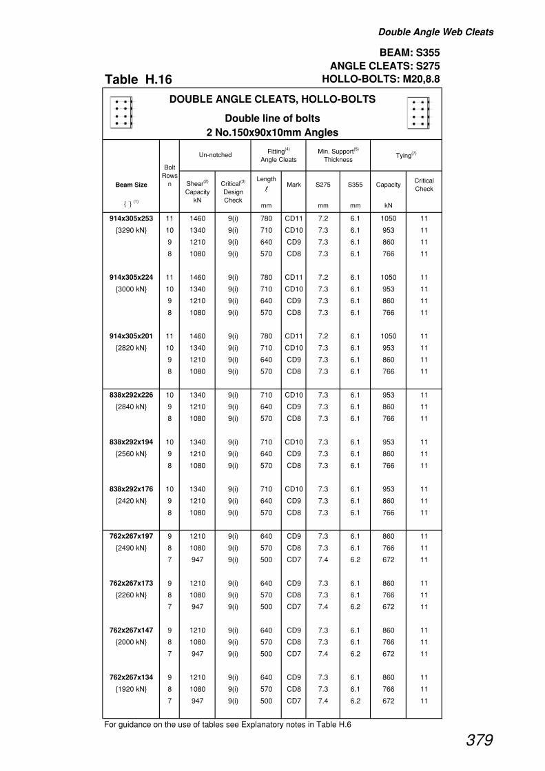
Double Angle Web Cleats
BEAM: S355 ANGLE CLEATS: S275
Table H.16 HOLLO-BOLTS: M20,8.8
Beam SizeLength
�Mark S275 S355 Capacity
Critical Check
{ } (1)mm mm mm kN
914x305x253 11 1460 9(i) 780 CD11 7.2 6.1 1050 11
{3290 kN} 10 1340 9(i) 710 CD10 7.3 6.1 953 11
9 1210 9(i) 640 CD9 7.3 6.1 860 11
8 1080 9(i) 570 CD8 7.3 6.1 766 11
914x305x224 11 1460 9(i) 780 CD11 7.2 6.1 1050 11
{3000 kN} 10 1340 9(i) 710 CD10 7.3 6.1 953 11
9 1210 9(i) 640 CD9 7.3 6.1 860 11
8 1080 9(i) 570 CD8 7.3 6.1 766 11
914x305x201 11 1460 9(i) 780 CD11 7.2 6.1 1050 11
{2820 kN} 10 1340 9(i) 710 CD10 7.3 6.1 953 11
9 1210 9(i) 640 CD9 7.3 6.1 860 11
8 1080 9(i) 570 CD8 7.3 6.1 766 11
838x292x226 10 1340 9(i) 710 CD10 7.3 6.1 953 11
{2840 kN} 9 1210 9(i) 640 CD9 7.3 6.1 860 11
8 1080 9(i) 570 CD8 7.3 6.1 766 11
838x292x194 10 1340 9(i) 710 CD10 7.3 6.1 953 11
{2560 kN} 9 1210 9(i) 640 CD9 7.3 6.1 860 11
8 1080 9(i) 570 CD8 7.3 6.1 766 11
838x292x176 10 1340 9(i) 710 CD10 7.3 6.1 953 11
{2420 kN} 9 1210 9(i) 640 CD9 7.3 6.1 860 11
8 1080 9(i) 570 CD8 7.3 6.1 766 11
762x267x197 9 1210 9(i) 640 CD9 7.3 6.1 860 11
{2490 kN} 8 1080 9(i) 570 CD8 7.3 6.1 766 11
7 947 9(i) 500 CD7 7.4 6.2 672 11
762x267x173 9 1210 9(i) 640 CD9 7.3 6.1 860 11
{2260 kN} 8 1080 9(i) 570 CD8 7.3 6.1 766 11
7 947 9(i) 500 CD7 7.4 6.2 672 11
762x267x147 9 1210 9(i) 640 CD9 7.3 6.1 860 11
{2000 kN} 8 1080 9(i) 570 CD8 7.3 6.1 766 11
7 947 9(i) 500 CD7 7.4 6.2 672 11
762x267x134 9 1210 9(i) 640 CD9 7.3 6.1 860 11
{1920 kN} 8 1080 9(i) 570 CD8 7.3 6.1 766 11
7 947 9(i) 500 CD7 7.4 6.2 672 11
For guidance on the use of tables see Explanatory notes in Table H.6
DOUBLE ANGLE CLEATS, HOLLO-BOLTS
Double line of bolts2 No.150x90x10mm Angles
Fitting(4)
Angle CleatsMin. Support(5)
ThicknessTying(7)
Bolt Rows
n
Un-notched
Shear(2)
Capacity kN
Critical(3)
Design Check
379

Double Angle Web Cleats
BEAM: S355 ANGLE CLEATS: S275
Table H.16 Continued HOLLO-BOLTS: M20,8.8
Beam SizeLength
�Mark S275 S355 Capacity
Critical Check
{ } (1)mm mm mm kN
DOUBLE ANGLE CLEATS, HOLLO-BOLTS
Double line of bolts2 No.150x90x10mm Angles
Fitting(4)
Angle CleatsMin. Support(5)
ThicknessTying(7)
Bolt Rows
n
Un-notched
Shear(2)
Capacity kN
Critical(3)
Design Check
686x254x170 8 1080 9(i) 570 CD8 7.3 6.1 766 11
{2080 kN} 7 947 9(i) 500 CD7 7.4 6.2 672 11
6 818 9(i) 430 CD6 7.4 6.2 580 11
686x254x152 8 1080 9(i) 570 CD8 7.3 6.1 766 11
{1880 kN} 7 947 9(i) 500 CD7 7.4 6.2 672 11
6 818 9(i) 430 CD6 7.4 6.2 580 11
686x254x140 8 1080 9(i) 570 CD8 7.3 6.1 766 11
{1750 kN} 7 947 9(i) 500 CD7 7.4 6.2 672 11
6 818 9(i) 430 CD6 7.4 6.2 580 11
686x254x125 8 1080 9(i) 570 CD8 7.3 6.1 766 11
{1640 kN} 7 947 9(i) 500 CD7 7.4 6.2 672 11
6 818 9(i) 430 CD6 7.4 6.2 580 11
610x305x238 7 947 9(i) 500 CD7 7.4 6.2 672 11
{2420 kN} 6 818 9(i) 430 CD6 7.4 6.2 580 11
610x305x179 7 947 9(i) 500 CD7 7.4 6.2 672 11
{1810 kN} 6 818 9(i) 430 CD6 7.4 6.2 580 11
610x305x149 7 947 9(i) 500 CD7 7.4 6.2 672 11
{1500 kN} 6 818 9(i) 430 CD6 7.4 6.2 580 11
610x229x140 7 947 9(i) 500 CD7 7.4 6.2 672 11
{1670 kN} 6 818 9(i) 430 CD6 7.4 6.2 580 11
610x229x125 7 947 9(i) 500 CD7 7.4 6.2 672 11
{1510 kN} 6 818 9(i) 430 CD6 7.4 6.2 580 11
610x229x113 7 947 9(i) 500 CD7 7.4 6.2 672 11
{1400 kN} 6 818 9(i) 430 CD6 7.4 6.2 580 11
610x229x101 7 947 9(i) 500 CD7 7.4 6.2 672 11
{1350 kN} 6 818 9(i) 430 CD6 7.4 6.2 580 11
For guidance on the use of tables see Explanatory notes in Table H.6
380
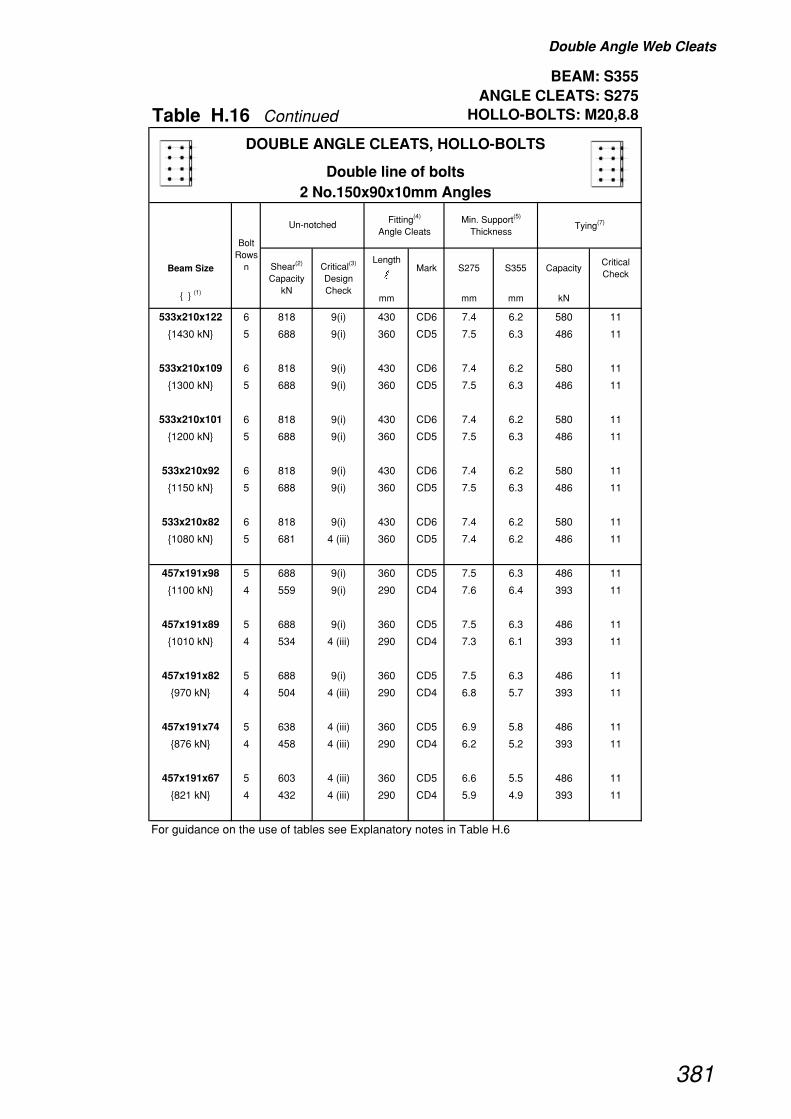
Double Angle Web Cleats
BEAM: S355 ANGLE CLEATS: S275
Table H.16 Continued HOLLO-BOLTS: M20,8.8
Beam SizeLength
�Mark S275 S355 Capacity
Critical Check
{ } (1)mm mm mm kN
DOUBLE ANGLE CLEATS, HOLLO-BOLTS
Double line of bolts2 No.150x90x10mm Angles
Fitting(4)
Angle CleatsMin. Support(5)
ThicknessTying(7)
Bolt Rows
n
Un-notched
Shear(2)
Capacity kN
Critical(3)
Design Check
533x210x122 6 818 9(i) 430 CD6 7.4 6.2 580 11
{1430 kN} 5 688 9(i) 360 CD5 7.5 6.3 486 11
533x210x109 6 818 9(i) 430 CD6 7.4 6.2 580 11
{1300 kN} 5 688 9(i) 360 CD5 7.5 6.3 486 11
533x210x101 6 818 9(i) 430 CD6 7.4 6.2 580 11
{1200 kN} 5 688 9(i) 360 CD5 7.5 6.3 486 11
533x210x92 6 818 9(i) 430 CD6 7.4 6.2 580 11
{1150 kN} 5 688 9(i) 360 CD5 7.5 6.3 486 11
533x210x82 6 818 9(i) 430 CD6 7.4 6.2 580 11
{1080 kN} 5 681 4 (iii) 360 CD5 7.4 6.2 486 11
457x191x98 5 688 9(i) 360 CD5 7.5 6.3 486 11
{1100 kN} 4 559 9(i) 290 CD4 7.6 6.4 393 11
457x191x89 5 688 9(i) 360 CD5 7.5 6.3 486 11
{1010 kN} 4 534 4 (iii) 290 CD4 7.3 6.1 393 11
457x191x82 5 688 9(i) 360 CD5 7.5 6.3 486 11
{970 kN} 4 504 4 (iii) 290 CD4 6.8 5.7 393 11
457x191x74 5 638 4 (iii) 360 CD5 6.9 5.8 486 11
{876 kN} 4 458 4 (iii) 290 CD4 6.2 5.2 393 11
457x191x67 5 603 4 (iii) 360 CD5 6.6 5.5 486 11
{821 kN} 4 432 4 (iii) 290 CD4 5.9 4.9 393 11
For guidance on the use of tables see Explanatory notes in Table H.6
381

Double Angle Web Cleats
BEAM: S355 ANGLE CLEATS: S275
Table H.16 Continued HOLLO-BOLTS: M20,8.8
Beam SizeLength
�Mark S275 S355 Capacity
Critical Check
{ } (1)mm mm mm kN
DOUBLE ANGLE CLEATS, HOLLO-BOLTS
Double line of bolts2 No.150x90x10mm Angles
Fitting(4)
Angle CleatsMin. Support(5)
ThicknessTying(7)
Bolt Rows
n
Un-notched
Shear(2)
Capacity kN
Critical(3)
Design Check
457x152x82 5 688 9(i) 360 CD5 7.5 6.3 486 11
{1010 kN} 4 534 4 (iii) 290 CD4 7.3 6.1 393 11
457x152x74 5 675 4(ii) 360 CD5 7.3 6.1 486 11
{918 kN} 4 488 4 (iii) 290 CD4 6.6 5.5 393 11
457x152x67 5 638 4 (iii) 360 CD5 6.9 5.8 486 11
{878 kN} 4 458 4 (iii) 290 CD4 6.2 5.2 393 11
457x152x60 5 574 4 (iii) 360 CD5 6.2 5.2 486 11
{784 kN} 4 412 4 (iii) 290 CD4 5.6 4.7 393 11
457x152x52 5 539 4 (iii) 360 CD5 5.9 4.9 486 11
{728 kN} 4 387 4 (iii) 290 CD4 5.3 4.4 393 11
406x178x74 4 483 4 (iii) 290 CD4 6.6 5.5 393 11
{835 kN}
406x178x67 4 448 4 (iii) 290 CD4 6.1 5.1 393 11
{767 kN}
406x178x60 4 402 4 (iii) 290 CD4 5.5 4.6 393 11
{684 kN}
406x178x54 4 392 4 (iii) 290 CD4 5.3 4.5 393 11
{660 kN}
406x140x46 4 346 4 (iii) 290 CD4 4.7 3.9 393 11
{584 kN}
406x140x39 4 325 4 (iii) 290 CD4 4.4 3.7 393 11
{543 kN}
356x171x67 3 300 4 (iii) 220 CD3 5.4 4.5 299 11
{704 kN}
356x171x57 3 267 4 (iii) 220 CD3 4.8 4.0 299 11
{618 kN}
356x171x51 3 244 4 (iii) 220 CD3 4.4 3.7 299 11
{560 kN}
356x171x45 3 231 4 (iii) 220 CD3 4.2 3.5 299 11
{524 kN}
356x127x39 3 217 4 (iii) 220 CD3 3.9 3.3 299 11
{497 kN}
356x127x33 3 198 4 (iii) 220 CD3 3.6 3.0 299 11
{446 kN}
For guidance on the use of tables see Explanatory notes in Table H.6
382
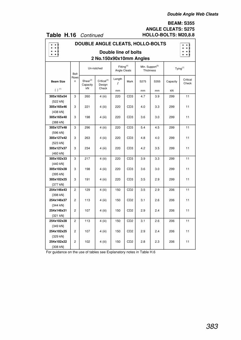
Double Angle Web Cleats
BEAM: S355 ANGLE CLEATS: S275
Table H.16 Continued HOLLO-BOLTS: M20,8.8
Beam SizeLength
�Mark S275 S355 Capacity
Critical Check
{ } (1)mm mm mm kN
DOUBLE ANGLE CLEATS, HOLLO-BOLTS
Double line of bolts2 No.150x90x10mm Angles
Fitting(4)
Angle CleatsMin. Support(5)
ThicknessTying(7)
Bolt Rows
n
Un-notched
Shear(2)
Capacity kN
Critical(3)
Design Check
305x165x54 3 260 4 (iii) 220 CD3 4.7 3.9 299 11
{522 kN}
305x165x46 3 221 4 (iii) 220 CD3 4.0 3.3 299 11
{438 kN}
305x165x40 3 198 4 (iii) 220 CD3 3.6 3.0 299 11
{388 kN}
305x127x48 3 296 4 (iii) 220 CD3 5.4 4.5 299 11
{596 kN}
305x127x42 3 263 4 (iii) 220 CD3 4.8 4.0 299 11
{523 kN}
305x127x37 3 234 4 (iii) 220 CD3 4.2 3.5 299 11
{460 kN}
305x102x33 3 217 4 (iii) 220 CD3 3.9 3.3 299 11
{440 kN}
305x102x28 3 198 4 (iii) 220 CD3 3.6 3.0 299 11
{395 kN}
305x102x25 3 191 4 (iii) 220 CD3 3.5 2.9 299 11
{377 kN}
254x146x43 2 129 4 (iii) 150 CD2 3.5 2.9 206 11
{398 kN}
254x146x37 2 113 4 (iii) 150 CD2 3.1 2.6 206 11
{344 kN}
254x146x31 2 107 4 (iii) 150 CD2 2.9 2.4 206 11
{321 kN}
254x102x28 2 113 4 (iii) 150 CD2 3.1 2.6 206 11
{349 kN}
254x102x25 2 107 4 (iii) 150 CD2 2.9 2.4 206 11
{329 kN}
254x102x22 2 102 4 (iii) 150 CD2 2.8 2.3 206 11
{308 kN}
For guidance on the use of tables see Explanatory notes in Table H.6
383
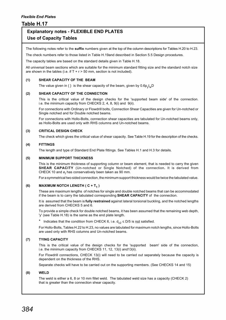
Flexible End Plates
384
Table H.17 Explanatory notes - FLEXIBLE END PLATES
Use of Capacity Tables
The following notes refer to the suffix numbers given at the top of the column descriptions for Tables H.20 to H.23.
The check numbers refer to those listed in Table H.19and described in Section 5.5 Design procedures.
The capacity tables are based on the standard details given in Table H.18.
All universal beam sections which are suitable for the minimum standard fitting size and the standard notch sizeare shown in the tables (i.e. if T + r > 50 mm, section is not included).
(1) SHEAR CAPACITY OF THE BEAM
The value given in { } is the shear capacity of the beam, given by 0.6pytwD
(2) SHEAR CAPACITY OF THE CONNECTION
This is the critical value of the design checks for the 'supported beam side' of the connection.i.e. the minimum capacity from CHECKS 2, 4, 8, 9(i) and 9(ii).
For connections with Ordinary or Flowdrill bolts, Connection Shear Capacities are given for Un-notched orSingle notched and for Double notched beams.
For connections with Hollo-Bolts, connection shear capacities are tabulated for Un-notched beams only,as Hollo-Bolts are used only with RHS columns and Un-notched beams.
(3) CRITICAL DESIGN CHECK
The check which gives the critical value of shear capacity. See Table H.19 for the description of the checks.
(4) FITTINGS
The length and type of Standard End Plate fittings. See Tables H.1 and H.3 for details.
(5) MINIMUM SUPPORT THICKNESS
This is the minimum thickness of supporting column or beam element, that is needed to carry the givenSHEAR CAPACITY (Un-notched or Single Notched) of the connection. It is derived fromCHECK 10 and et has conservatively been taken as 90 mm.
For a symmetrical two sided connection, the minimum support thickness would be twice the tabulated value.
(6) MAXIMUM NOTCH LENGTH ( C + T1 )
These are maximum lengths of notches for single and double notched beams that can be accommodatedif the beam is to carry the tabulated corresponding SHEAR CAPACITY of the connection.
It is assumed that the beam is fully restrained against lateral torsional buckling, and the notched lengthsare derived from CHECKS 5 and 6.
To provide a simple check for double notched beams, it has been assumed that the remaining web depth,'y' (see Table H.18) is the same as the end plate length.
* Indicates that the condition from CHECK 6, i.e. dc2 ≤ D/5 is not satisfied.
For Hollo-Bolts, Tables H.22 to H.23, no values are tabulated for maximum notch lengths, since Hollo-Boltsare used only with RHS columns and Un-notched beams.
(7) TYING CAPACITY
This is the critical value of the design checks for the 'supported beam' side of the connection,i.e. the minimum capacity from CHECKS 11, 12, 13(i) and13(ii).
For Flowdrill connections, CHECK 13(i) will need to be carried out separately because the capacity isdependent on the thickness of the RHS.
Separate checks will have to be carried out on the supporting members. (See CHECKS 14 and 15)
(8) WELD
The weld is either a 6, 8 or 10 mm fillet weld. The tabulated weld size has a capacity (CHECK 2)that is greater than the connection shear capacity.
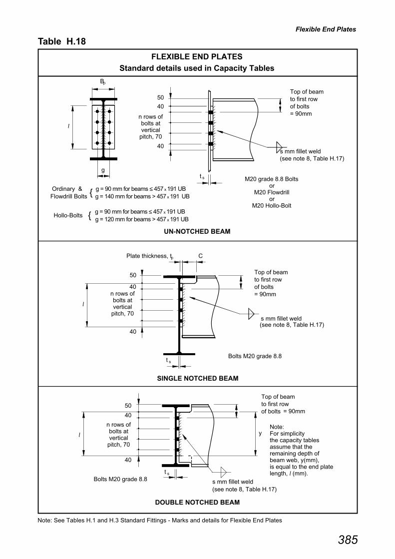
Flexible End Plates
385
Table H.18
FLEXIBLE END PLATES
Standard details used in Capacity Tables
Note: See Tables H.1 and H.3 Standard Fittings - Marks and details for Flexible End Plates
Ordinary & { g = 90 mm for beams ≤ 457 x 191 UBFlowdrill Bolts g = 140 mm for beams > 457 x 191 UB
Hollo-Bolts { g = 90 mm for beams ≤ 457 x 191 UB
g = 120 mm for beams > 457 x 191 UB
DOUBLE NOTCHED BEAM
UN-NOTCHED BEAM
SINGLE NOTCHED BEAM
p
g
Top of beamto first rowof bolts= 90mm
50
40
40s mm fillet weld
Top of beamto first rowof bolts= 90mm
Top of beamto first rowof bolts = 90mm
50
40
40
50
40
40
st
s mm fillet weld
s mm fillet weld
Bolts M20 grade 8.8
Bolts M20 grade 8.8
(see note 8, Table H.17)
(see note 8, Table H.17)
CPlate thickness, t
(see note 8, Table H.17)
B
n rows of bolts at vertical
pitch, 70
t s
n rows of bolts at vertical
pitch, 70
p
n rows of bolts at vertical
pitch, 70
st
Note: For simplicity the capacity tables assume that the remaining depth of beam web, y(mm), is equal to the end plate length, l (mm).
y
M20 grade 8.8 Bolts
or M20 Flowdrill
or M20 Hollo-Bolt
l
l
l
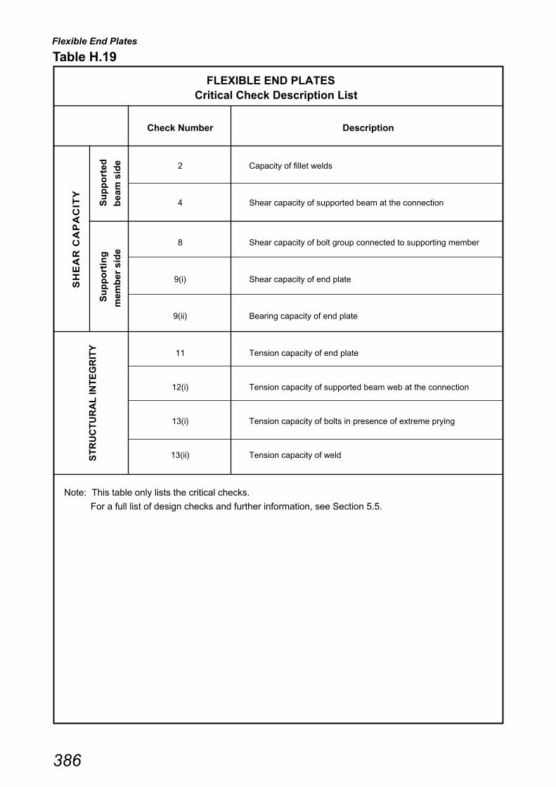
Flexible End Plates
386
Check Number Description
2 Capacity of fillet welds
4 Shear capacity of supported beam at the connection
8 Shear capacity of bolt group connected to supporting member
9(i) Shear capacity of end plate
9(ii) Bearing capacity of end plate
11 Tension capacity of end plate
12(i) Tension capacity of supported beam web at the connection
13(i) Tension capacity of bolts in presence of extreme prying
13(ii) Tension capacity of weld
SH
EA
R C
AP
AC
ITY
ST
RU
CT
UR
AL
INT
EG
RIT
Y
S
up
po
rtin
g
Su
pp
ort
ed
mem
ber
sid
e
bea
m s
ide
Table H.19
FLEXIBLE END PLATESCritical Check Description List
Note: This table only lists the critical checks.
For a full list of design checks and further information, see Section 5.5.

Flexible End Plates
BEAM: S275END PLATE: S275
Table H.20 BOLTS: M20, 8.8
Beam Size Width tpLength
�
Bolt(4)
Gauge g
Mark(4) S275 S355 Single Double CapacityCritical Check
{ } (1)mm mm mm mm mm mm mm mm mm kN
914x305x253 11 1930 4 1930 4 200 10 780 140 EB11 10 9.5 8.0 390 0 585 11
{2530 kN} 10 1760 4 1760 4 200 10 710 140 EB10 10 9.6 8.0 485 0 532 11
9 1580 4 1580 4 200 10 640 140 EB9 10 9.6 8.0 538 0 480 11
8 1410 4 1410 4 200 10 570 140 EB8 10 9.6 8.0 605 0 427 11
914x305x224 11 1770 4 1770 4 200 10 780 140 EB11 8 8.8 7.3 374 0 549 11
{2300 kN} 10 1620 4 1620 4 200 10 710 140 EB10 8 8.8 7.3 473 0 499 11
9 1460 4 1460 4 200 10 640 140 EB9 8 8.8 7.4 525 0 450 11
8 1300 4 1300 4 200 10 570 140 EB8 8 8.8 7.4 590 0 400 11
914x305x201 11 1690 4 1690 4 200 10 780 140 EB11 8 8.3 7.0 356 0 544 11
{2170 kN} 10 1530 4 1530 4 200 10 710 140 EB10 8 8.3 7.0 459 0 494 11
9 1380 4 1380 4 200 10 640 140 EB9 8 8.4 7.0 509 0 445 11
8 1230 4 1230 4 200 10 570 140 EB8 8 8.4 7.0 571 0 396 11
838x292x226 10 1640 4 1640 4 200 10 710 140 EB10 8 8.9 7.4 377 0 500 11
{2180 kN} 9 1470 4 1470 4 200 10 640 140 EB9 8 8.9 7.4 463 0 451 11
8 1310 4 1310 4 200 10 570 140 EB8 8 8.9 7.5 520 0 401 11
838x292x194 10 1490 4 1490 4 200 10 710 140 EB10 8 8.1 6.8 355 0 492 11
{1960 kN} 9 1350 4 1350 4 200 10 640 140 EB9 8 8.1 6.8 446 0 443 11
8 1200 4 1200 4 200 10 570 140 EB8 8 8.1 6.8 500 0 395 11
838x292x176 10 1420 4 1420 4 200 10 710 140 EB10 8 7.7 6.5 341 0 488 11
{1860 kN} 9 1280 4 1280 4 200 10 640 140 EB9 8 7.7 6.5 434 0 440 11
8 1140 4 1140 4 200 10 570 140 EB8 8 7.8 6.5 487 0 391 11
762x267x197 9 1430 4 1430 4 200 10 640 140 EB9 8 8.6 7.2 335 0 448 11
{1910 kN} 8 1270 4 1270 4 200 10 570 140 EB8 8 8.6 7.2 419 0 399 11
7 1120 4 1120 4 200 10 500 140 EB7 8 8.7 7.2 477 0 349 11
762x267x173 9 1310 4 1310 4 200 10 640 140 EB9 8 7.9 6.6 320 0 441 11
{1730 kN} 8 1170 4 1170 4 200 10 570 140 EB8 8 7.9 6.6 407 0 393 11
7 1020 4 1020 4 200 10 500 140 EB7 8 7.9 6.6 464 0 344 11
762x267x147 9 1170 4 1170 4 200 10 640 140 EB9 8 7.1 5.9 303 0 434 11
{1530 kN} 8 1040 4 1040 4 200 10 570 140 EB8 8 7.1 5.9 394 0 386 11
7 916 4 916 4 200 10 500 140 EB7 8 7.1 5.9 449 0 338 11
762x267x134 9 1140 4 1140 4 200 10 640 140 EB9 6 6.9 5.8 294 0 412 11
{1490 kN} 8 1020 4 1020 4 200 10 570 140 EB8 6 6.9 5.8 387 0 366 11
7 891 4 891 4 200 10 500 140 EB7 6 6.9 5.8 441 0 321 11
For guidance on the use of tables see Explanatory notes in Table H.17
Bolt Rows
n
Tying(7)
Shear(2)
Capacity kN
Fitting(4)
End PlateUn-notched
or Single Notch
Critical(3)
Design Check
Min.
Support(5)
Thickness
Shear(2)
Capacity kN
Critical(3)
Design Check
Max. Notch
Length(6)
c+tpFillet(8)
weld s
Double Notch
FLEXIBLE END PLATES, ORDINARY or FLOWDRILL BOLTS
200x10 or 150x8 mm End Plate
387

Flexible End Plates
BEAM: S275END PLATE: S275
Table H.20 Continued BOLTS: M20, 8.8
Beam Size Width tpLength
�
Bolt(4)
Gauge g
Mark(4) S275 S355 Single Double CapacityCritical Check
{ } (1)mm mm mm mm mm mm mm mm mm kN
Bolt Rows
n
Tying(7)
Shear(2)
Capacity kN
Fitting(4)
End PlateUn-notched
or Single Notch
Critical(3)
Design Check
Min.
Support(5)
Thickness
Shear(2)
Capacity kN
Critical(3)
Design Check
Max. Notch
Length(6)
c+tpFillet(8)
weld s
Double Notch
FLEXIBLE END PLATES, ORDINARY or FLOWDRILL BOLTS
200x10 or 150x8 mm End Plate
686x254x170 8 1180 4 1180 4 200 10 570 140 EB8 8 8.0 6.7 305 0 394 11
{1600 kN} 7 1040 4 1040 4 200 10 500 140 EB7 8 8.1 6.7 385 0 345 11
6 892 4 892 4 200 10 430 140 EB6 8 8.1 6.8 447 0 296 11
686x254x152 8 1080 4 1080 4 200 10 570 140 EB8 8 7.3 6.1 295 0 388 11
{1440 kN} 7 944 4 944 4 200 10 500 140 EB7 8 7.3 6.1 378 0 340 11
6 812 4 812 4 200 10 430 140 EB6 8 7.4 6.2 440 0 292 11
686x254x140 8 1010 4 1010 4 200 10 570 140 EB8 6 6.9 5.7 288 0 368 11
{1350 kN} 7 887 4 887 4 200 10 500 140 EB7 6 6.9 5.8 372 0 322 11
6 763 4 763 4 200 10 430 140 EB6 6 6.9 5.8 433 0 277 11
686x254x125 8 954 4 954 4 200 10 570 140 EB8 6 6.5 5.4 274 0 365 11
{1260 kN} 7 837 4 837 4 200 10 500 140 EB7 6 6.5 5.4 362 0 320 11
6 720 4 720 4 200 10 430 140 EB6 6 6.5 5.5 421 0 275 11
610x305x238 7 1290 8 1290 8 200 10 500 140 EB7 10 10.0 8.4 335 51 379 11
{1860 kN} 6 1100 8 1100 8 200 10 430 140 EB6 10 10.0 8.4 395 47* 326 11
610x305x179 7 1010 4 1010 4 200 10 500 140 EB7 8 7.8 6.6 292 0 343 11
{1390 kN} 6 868 4 868 4 200 10 430 140 EB6 8 7.9 6.6 368 0 295 11
610x305x149 7 844 4 844 4 200 10 500 140 EB7 6 6.6 5.5 279 0 320 11
{1150 kN} 6 726 4 726 4 200 10 430 140 EB6 6 6.6 5.5 360 0 275 11
610x229x140 7 937 4 937 4 200 10 500 140 EB7 8 7.3 6.1 275 0 339 11
{1290 kN} 6 806 4 806 4 200 10 430 140 EB6 8 7.3 6.1 350 0 291 11
610x229x125 7 851 4 851 4 200 10 500 140 EB7 6 6.6 5.5 266 0 321 11
{1160 kN} 6 732 4 732 4 200 10 430 140 EB6 6 6.6 5.5 344 0 275 11
610x229x113 7 794 4 794 4 200 10 500 140 EB7 6 6.2 5.2 257 0 318 11
{1070 kN} 6 683 4 683 4 200 10 430 140 EB6 6 6.2 5.2 337 0 273 11
610x229x101 7 780 4 780 4 200 10 500 140 EB7 6 6.1 5.1 245 0 316 11
{1040 kN} 6 670 4 670 4 200 10 430 140 EB6 6 6.1 5.1 328 0 271 11
For guidance on the use of tables see Explanatory notes in Table H.17
388

Flexible End Plates
BEAM: S275END PLATE: S275
Table H.20 Continued BOLTS: M20, 8.8
Beam Size Width tpLength
�
Bolt(4)
Gauge g
Mark(4) S275 S355 Single Double CapacityCritical Check
{ } (1)mm mm mm mm mm mm mm mm mm kN
Bolt Rows
n
Tying(7)
Shear(2)
Capacity kN
Fitting(4)
End PlateUn-notched
or Single Notch
Critical(3)
Design Check
Min.
Support(5)
Thickness
Shear(2)
Capacity kN
Critical(3)
Design Check
Max. Notch
Length(6)
c+tpFillet(8)
weld s
Double Notch
FLEXIBLE END PLATES, ORDINARY or FLOWDRILL BOLTS
200x10 or 150x8 mm End Plate
533x210x122 6 781 4 781 4 200 10 430 140 EB6 8 7.1 5.9 249 0 290 11
{1100 kN} 5 654 4 654 4 200 10 360 140 EB5 8 7.1 5.9 319 0 242 11
533x210x109 6 714 4 714 4 200 10 430 140 EB6 6 6.5 5.4 240 0 274 11
{995 kN} 5 598 4 598 4 200 10 360 140 EB5 6 6.5 5.4 313 0 229 11
533x210x101 6 665 4 665 4 200 10 430 140 EB6 6 6.0 5.0 236 0 272 11
{922 kN} 5 556 4 556 4 200 10 360 140 EB5 6 6.0 5.1 310 0 227 11
533x210x92 6 645 4 645 4 200 10 430 140 EB6 6 5.8 4.9 229 0 270 11
{888 kN} 5 540 4 540 4 200 10 360 140 EB5 6 5.9 4.9 304 0 226 11
533x210x82 6 613 4 613 4 200 10 430 140 EB6 6 5.6 4.6 217 0 269 11
{837 kN} 5 513 4 513 4 200 10 360 140 EB5 6 5.6 4.7 295 0 225 11
457x191x98 5 587 4 587 4 150 8 360 90 EA5 6 6.4 5.3 217 0 311 11
{847 kN} 4 473 4 473 4 150 8 290 90 EA4 6 6.4 5.4 285 0 249 11
457x191x89 5 541 4 541 4 150 8 360 90 EA5 6 5.9 4.9 211 0 304 11
{774 kN} 4 436 4 436 4 150 8 290 90 EA4 6 5.9 5.0 281 0 245 11
457x191x82 5 529 4 529 4 150 8 360 90 EA5 6 5.8 4.8 204 0 301 11
{751 kN} 4 426 4 426 4 150 8 290 90 EA4 6 5.8 4.8 275 0 241 11
457x191x74 5 481 4 481 4 150 8 360 90 EA5 6 5.2 4.4 199 0 295 11
{679 kN} 4 388 4 388 4 150 8 290 90 EA4 6 5.3 4.4 272 0 237 11
457x191x67 5 454 4 454 4 150 8 360 90 EA5 6 4.9 4.1 191 0 292 11
{636 kN} 4 366 4 366 4 150 8 290 90 EA4 6 5.0 4.2 266 0 234 11
For guidance on the use of tables see Explanatory notes in Table H.17
389

Flexible End Plates
BEAM: S275END PLATE: S275
Table H.20 Continued BOLTS: M20, 8.8
Beam Size Width tpLength
�
Bolt(4)
Gauge g
Mark(4) S275 S355 Single Double CapacityCritical Check
{ } (1)mm mm mm mm mm mm mm mm mm kN
Bolt Rows
n
Tying(7)
Shear(2)
Capacity kN
Fitting(4)
End PlateUn-notched
or Single Notch
Critical(3)
Design Check
Min.
Support(5)
Thickness
Shear(2)
Capacity kN
Critical(3)
Design Check
Max. Notch
Length(6)
c+tpFillet(8)
weld s
Double Notch
FLEXIBLE END PLATES, ORDINARY or FLOWDRILL BOLTS
200x10 or 150x8 mm End Plate
457x152x82 5 541 4 541 4 150 8 360 90 EA5 6 5.9 4.9 209 0 304 11
{778 kN} 4 436 4 436 4 150 8 290 90 EA4 6 5.9 5.0 276 0 245 11
457x152x74 5 495 4 495 4 150 8 360 90 EA5 6 5.4 4.5 203 0 299 11
{705 kN} 4 398 4 398 4 150 8 290 90 EA4 6 5.4 4.5 272 0 240 11
457x152x67 5 481 4 481 4 150 8 360 90 EA5 6 5.2 4.4 195 0 295 11
{680 kN} 4 388 4 388 4 150 8 290 90 EA4 6 5.3 4.4 266 0 237 11
457x152x60 5 433 4 433 4 150 8 360 90 EA5 6 4.7 3.9 189 0 289 11
{608 kN} 4 349 4 349 4 150 8 290 90 EA4 6 4.7 4.0 262 0 232 11
457x152x52 5 406 4 406 4 150 8 360 90 EA5 6 4.4 3.7 178 0 286 11
{564 kN} 4 327 4 327 4 150 8 290 90 EA4 6 4.4 3.7 252 0 230 11
406x178x74 4 409 4 409 4 150 8 290 90 EA4 6 5.6 4.6 218 0 239 11
{647 kN}
406x178x67 4 379 4 379 4 150 8 290 90 EA4 6 5.1 4.3 214 0 236 11
{594 kN}
406x178x60 4 340 4 340 4 150 8 290 90 EA4 6 4.6 3.9 211 0 231 11
{530 kN}
406x178x54 4 332 4 332 4 150 8 290 90 EA4 6 4.5 3.8 204 0 230 11
{512 kN}
406x140x46 4 293 4 293 4 150 8 290 90 EA4 6 4.0 3.3 202 0 226 11
{452 kN}
406x140x39 4 276 4 276 4 150 8 290 90 EA4 6 3.7 3.1 191 0 224 11
{420 kN}
356x171x67 3 297 4 297 4 150 8 220 90 EA3 6 5.4 4.5 217 0 179 11
{546 kN}
356x171x57 3 265 4 265 4 150 8 220 90 EA3 6 4.8 4.0 210 0 175 11
{478 kN}
356x171x51 3 242 4 242 4 150 8 220 90 EA3 6 4.4 3.7 206 0 173 11
{433 kN}
356x171x45 3 229 4 229 4 150 8 220 90 EA3 6 4.1 3.5 199 0 171 11
{406 kN}
356x127x39 3 216 4 216 4 150 8 220 90 EA3 6 3.9 3.3 196 0 170 11
{385 kN}
356x127x33 3 196 4 196 4 150 8 220 90 EA3 6 3.6 3.0 188 0 168 11
{346 kN}
For guidance on the use of tables see Explanatory notes in Table H.17
390
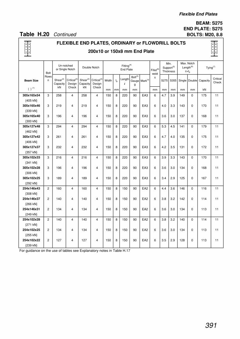
Flexible End Plates
BEAM: S275END PLATE: S275
Table H.20 Continued BOLTS: M20, 8.8
Beam Size Width tpLength
�
Bolt(4)
Gauge g
Mark(4) S275 S355 Single Double CapacityCritical Check
{ } (1)mm mm mm mm mm mm mm mm mm kN
Bolt Rows
n
Tying(7)
Shear(2)
Capacity kN
Fitting(4)
End PlateUn-notched
or Single Notch
Critical(3)
Design Check
Min.
Support(5)
Thickness
Shear(2)
Capacity kN
Critical(3)
Design Check
Max. Notch
Length(6)
c+tpFillet(8)
weld s
Double Notch
FLEXIBLE END PLATES, ORDINARY or FLOWDRILL BOLTS
200x10 or 150x8 mm End Plate
305x165x54 3 258 4 258 4 150 8 220 90 EA3 6 4.7 3.9 149 0 175 11
{405 kN}
305x165x46 3 219 4 219 4 150 8 220 90 EA3 6 4.0 3.3 143 0 170 11
{339 kN}
305x165x40 3 196 4 196 4 150 8 220 90 EA3 6 3.6 3.0 137 0 168 11
{300 kN}
305x127x48 3 294 4 294 4 150 8 220 90 EA3 6 5.3 4.5 141 0 179 11
{462 kN}
305x127x42 3 261 4 261 4 150 8 220 90 EA3 6 4.7 4.0 135 0 175 11
{406 kN}
305x127x37 3 232 4 232 4 150 8 220 90 EA3 6 4.2 3.5 131 0 172 11
{357 kN}
305x102x33 3 216 4 216 4 150 8 220 90 EA3 6 3.9 3.3 143 0 170 11
{341 kN}
305x102x28 3 196 4 196 4 150 8 220 90 EA3 6 3.6 3.0 134 0 168 11
{306 kN}
305x102x25 3 189 4 189 4 150 8 220 90 EA3 6 3.4 2.9 125 0 167 11
{292 kN}
254x146x43 2 160 4 160 4 150 8 150 90 EA2 6 4.4 3.6 146 0 116 11
{308 kN}
254x146x37 2 140 4 140 4 150 8 150 90 EA2 6 3.8 3.2 142 0 114 11
{266 kN}
254x146x31 2 134 4 134 4 150 8 150 90 EA2 6 3.6 3.0 134 0 113 11
{249 kN}
254x102x28 2 140 4 140 4 150 8 150 90 EA2 6 3.8 3.2 140 0 114 11
{271 kN}
254x102x25 2 134 4 134 4 150 8 150 90 EA2 6 3.6 3.0 134 0 113 11
{255 kN}
254x102x22 2 127 4 127 4 150 8 150 90 EA2 6 3.5 2.9 128 0 113 11
{239 kN}
For guidance on the use of tables see Explanatory notes in Table H.17
391

Flexible End Plates
BEAM: S355END PLATE: S275
Table H.21 BOLTS: M20, 8.8
Beam Size Width tpLength
�
Bolt(4)
Gauge g
Mark(4) S275 S355 Single Double CapacityCritical Check
{ } (1)mm mm mm mm mm mm mm mm mm kN
914x305x253 11 2020 8 2020 8 200 10 780 140 EB11 10 10.0 8.4 550 267 585 11
{3290 kN} 10 1840 8 1840 8 200 10 710 140 EB10 10 10.0 8.4 604 244 532 11
9 1650 8 1650 8 200 10 640 140 EB9 10 10.0 8.4 672 221* 480 11
8 1470 8 1470 8 200 10 570 140 EB8 10 10.0 8.4 685 198* 427 11
914x305x224 11 2020 8 2020 8 200 10 780 140 EB11 10 10.0 8.4 493 200 575 11
{3000 kN} 10 1840 8 1840 8 200 10 710 140 EB10 10 10.0 8.4 542 183 523 11
9 1650 8 1650 8 200 10 640 140 EB9 10 10.0 8.4 543 166* 471 11
8 1470 8 1470 8 200 10 570 140 EB8 10 10.0 8.4 543 149* 419 11
914x305x201 11 2020 8 2020 8 200 10 780 140 EB11 10 10.0 8.4 443 153 570 11
{2820 kN} 10 1840 8 1840 8 200 10 710 140 EB10 10 10.0 8.4 474 140 518 11
9 1650 8 1650 8 200 10 640 140 EB9 10 10.0 8.4 474 128* 467 11
8 1470 8 1470 8 200 10 570 140 EB8 10 10.0 8.4 474 115* 415 11
838x292x226 10 1840 8 1840 8 200 10 710 140 EB10 10 10.0 8.4 484 193 525 11
{2840 kN} 9 1650 8 1650 8 200 10 640 140 EB9 10 10.0 8.4 537 175 473 11
8 1470 8 1470 8 200 10 570 140 EB8 10 10.0 8.4 605 157* 421 11
838x292x194 10 1840 8 1840 8 200 10 710 140 EB10 10 10.0 8.4 412 114 516 11
{2560 kN} 9 1650 8 1650 8 200 10 640 140 EB9 10 10.0 8.4 472 104 465 11
8 1470 8 1470 8 200 10 570 140 EB8 10 10.0 8.4 504 94* 413 11
838x292x176 10 1840 8 1840 8 200 10 710 140 EB10 10 10.0 8.4 349 41 512 11
{2420 kN} 9 1650 8 1650 8 200 10 640 140 EB9 10 10.0 8.4 438 41 461 11
8 1470 8 1470 8 200 10 570 140 EB8 10 10.0 8.4 443 40* 410 11
762x267x197 9 1650 8 1650 8 200 10 640 140 EB9 10 10.0 8.4 419 153 470 11
{2490 kN} 8 1470 8 1470 8 200 10 570 140 EB8 10 10.0 8.4 472 137 418 11
7 1290 8 1290 8 200 10 500 140 EB7 10 10.0 8.4 539 122* 366 11
762x267x173 9 1650 8 1650 8 200 10 640 140 EB9 10 10.0 8.4 348 74 462 11
{2260 kN} 8 1470 8 1470 8 200 10 570 140 EB8 10 10.0 8.4 421 68 411 11
7 1290 8 1290 8 200 10 500 140 EB7 10 10.0 8.4 481 62* 361 11
762x267x147 9 1530 4 1530 4 200 10 640 140 EB9 8 9.2 7.7 303 0 434 11
{2000 kN} 8 1360 4 1360 4 200 10 570 140 EB8 8 9.2 7.7 394 0 386 11
7 1190 4 1190 4 200 10 500 140 EB7 8 9.3 7.7 416 0 338 11
762x267x134 9 1470 4 1470 4 200 10 640 140 EB9 8 8.9 7.4 294 0 430 11
{1920 kN} 8 1310 4 1310 4 200 10 570 140 EB8 8 8.9 7.5 348 0 383 11
7 1150 4 1150 4 200 10 500 140 EB7 8 8.9 7.5 348 0 335 11
For guidance on the use of tables see Explanatory notes in Table H.17
Bolt Rows
n
Tying(7)
Shear(2)
Capacity kN
Fitting(4)
End PlateUn-notched
or Single Notch
Critical(3)
Design Check
Min.
Support(5)
Thickness
Shear(2)
Capacity kN
Critical(3)
Design Check
Max. Notch
Length(6)
c+tpFillet(8)
weld s
Double Notch
FLEXIBLE END PLATES, ORDINARY or FLOWDRILL BOLTS
200x10 or 150x8 mm End Plate
392
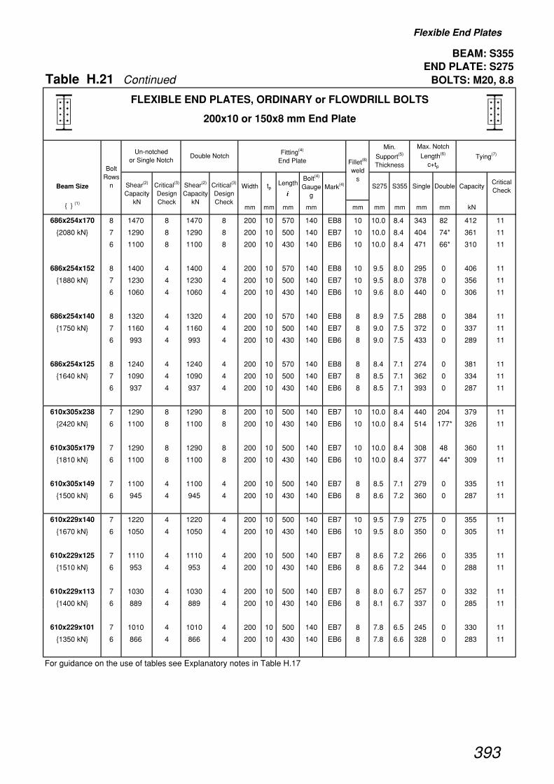
Flexible End Plates
BEAM: S355END PLATE: S275
Table H.21 Continued BOLTS: M20, 8.8
Beam Size Width tpLength
�
Bolt(4)
Gauge g
Mark(4) S275 S355 Single Double CapacityCritical Check
{ } (1)mm mm mm mm mm mm mm mm mm kN
Bolt Rows
n
Tying(7)
Shear(2)
Capacity kN
Fitting(4)
End PlateUn-notched
or Single Notch
Critical(3)
Design Check
Min.
Support(5)
Thickness
Shear(2)
Capacity kN
Critical(3)
Design Check
Max. Notch
Length(6)
c+tpFillet(8)
weld s
Double Notch
FLEXIBLE END PLATES, ORDINARY or FLOWDRILL BOLTS
200x10 or 150x8 mm End Plate
686x254x170 8 1470 8 1470 8 200 10 570 140 EB8 10 10.0 8.4 343 82 412 11
{2080 kN} 7 1290 8 1290 8 200 10 500 140 EB7 10 10.0 8.4 404 74* 361 11
6 1100 8 1100 8 200 10 430 140 EB6 10 10.0 8.4 471 66* 310 11
686x254x152 8 1400 4 1400 4 200 10 570 140 EB8 10 9.5 8.0 295 0 406 11
{1880 kN} 7 1230 4 1230 4 200 10 500 140 EB7 10 9.5 8.0 378 0 356 11
6 1060 4 1060 4 200 10 430 140 EB6 10 9.6 8.0 440 0 306 11
686x254x140 8 1320 4 1320 4 200 10 570 140 EB8 8 8.9 7.5 288 0 384 11
{1750 kN} 7 1160 4 1160 4 200 10 500 140 EB7 8 9.0 7.5 372 0 337 11
6 993 4 993 4 200 10 430 140 EB6 8 9.0 7.5 433 0 289 11
686x254x125 8 1240 4 1240 4 200 10 570 140 EB8 8 8.4 7.1 274 0 381 11
{1640 kN} 7 1090 4 1090 4 200 10 500 140 EB7 8 8.5 7.1 362 0 334 11
6 937 4 937 4 200 10 430 140 EB6 8 8.5 7.1 393 0 287 11
610x305x238 7 1290 8 1290 8 200 10 500 140 EB7 10 10.0 8.4 440 204 379 11
{2420 kN} 6 1100 8 1100 8 200 10 430 140 EB6 10 10.0 8.4 514 177* 326 11
610x305x179 7 1290 8 1290 8 200 10 500 140 EB7 10 10.0 8.4 308 48 360 11
{1810 kN} 6 1100 8 1100 8 200 10 430 140 EB6 10 10.0 8.4 377 44* 309 11
610x305x149 7 1100 4 1100 4 200 10 500 140 EB7 8 8.5 7.1 279 0 335 11
{1500 kN} 6 945 4 945 4 200 10 430 140 EB6 8 8.6 7.2 360 0 287 11
610x229x140 7 1220 4 1220 4 200 10 500 140 EB7 10 9.5 7.9 275 0 355 11
{1670 kN} 6 1050 4 1050 4 200 10 430 140 EB6 10 9.5 8.0 350 0 305 11
610x229x125 7 1110 4 1110 4 200 10 500 140 EB7 8 8.6 7.2 266 0 335 11
{1510 kN} 6 953 4 953 4 200 10 430 140 EB6 8 8.6 7.2 344 0 288 11
610x229x113 7 1030 4 1030 4 200 10 500 140 EB7 8 8.0 6.7 257 0 332 11
{1400 kN} 6 889 4 889 4 200 10 430 140 EB6 8 8.1 6.7 337 0 285 11
610x229x101 7 1010 4 1010 4 200 10 500 140 EB7 8 7.8 6.5 245 0 330 11
{1350 kN} 6 866 4 866 4 200 10 430 140 EB6 8 7.8 6.6 328 0 283 11
For guidance on the use of tables see Explanatory notes in Table H.17
393

Flexible End Plates
BEAM: S355END PLATE: S275
Table H.21 Continued BOLTS: M20, 8.8
Beam Size Width tpLength
�
Bolt(4)
Gauge g
Mark(4) S275 S355 Single Double CapacityCritical Check
{ } (1)mm mm mm mm mm mm mm mm mm kN
Bolt Rows
n
Tying(7)
Shear(2)
Capacity kN
Fitting(4)
End PlateUn-notched
or Single Notch
Critical(3)
Design Check
Min.
Support(5)
Thickness
Shear(2)
Capacity kN
Critical(3)
Design Check
Max. Notch
Length(6)
c+tpFillet(8)
weld s
Double Notch
FLEXIBLE END PLATES, ORDINARY or FLOWDRILL BOLTS
200x10 or 150x8 mm End Plate
533x210x122 6 1020 4 1020 4 200 10 430 140 EB6 8 9.2 7.7 249 0 290 11
{1430 kN} 5 852 4 852 4 200 10 360 140 EB5 10 9.3 7.7 319 0 254 11
533x210x109 6 929 4 929 4 200 10 430 140 EB6 8 8.4 7.0 240 0 287 11
{1300 kN} 5 778 4 778 4 200 10 360 140 EB5 8 8.5 7.1 313 0 239 11
533x210x101 6 865 4 865 4 200 10 430 140 EB6 8 7.8 6.6 236 0 284 11
{1200 kN} 5 724 4 724 4 200 10 360 140 EB5 8 7.9 6.6 310 0 237 11
533x210x92 6 833 4 833 4 200 10 430 140 EB6 8 7.5 6.3 229 0 282 11
{1150 kN} 5 697 4 697 4 200 10 360 140 EB5 8 7.6 6.3 304 0 236 11
533x210x82 6 791 4 791 4 200 10 430 140 EB6 8 7.2 6.0 217 0 280 11
{1080 kN} 5 663 4 663 4 200 10 360 140 EB5 8 7.2 6.0 295 0 234 11
457x191x98 5 736 9(ii) 736 9(ii) 150 8 360 90 EA5 8 8.0 6.7 239 47 341 11
{1100 kN} 4 589 9(ii) 589 9(ii) 150 8 290 90 EA4 8 8.0 6.7 298 41* 274 11
457x191x89 5 704 4 704 4 150 8 360 90 EA5 8 7.7 6.4 211 0 334 11
{1010 kN} 4 567 4 567 4 150 8 290 90 EA4 8 7.7 6.4 281 0 268 11
457x191x82 5 683 4 683 4 150 8 360 90 EA5 8 7.4 6.2 204 0 329 11
{970 kN} 4 550 4 550 4 150 8 290 90 EA4 8 7.5 6.3 275 0 264 11
457x191x74 5 621 4 621 4 150 8 360 90 EA5 6 6.8 5.6 199 0 295 11
{876 kN} 4 500 4 500 4 150 8 290 90 EA4 6 6.8 5.7 272 0 237 11
457x191x67 5 587 4 587 4 150 8 360 90 EA5 6 6.4 5.3 191 0 292 11
{821 kN} 4 473 4 473 4 150 8 290 90 EA4 6 6.4 5.4 266 0 234 11
For guidance on the use of tables see Explanatory notes in Table H.17
394
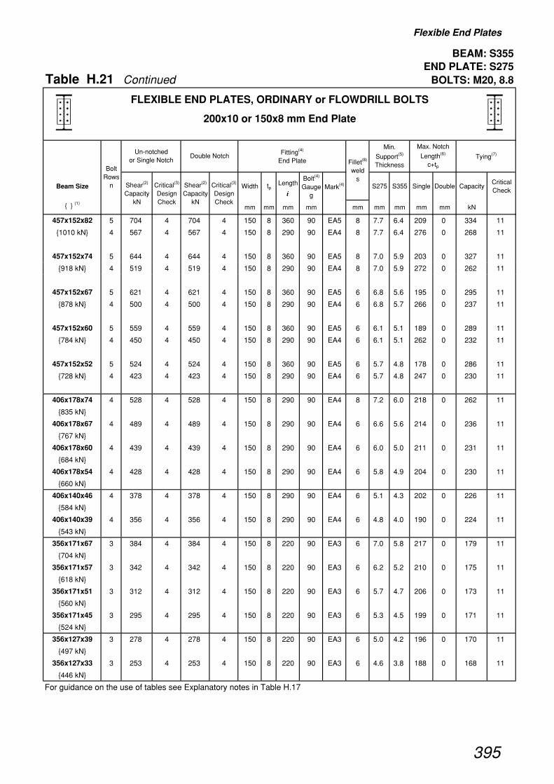
Flexible End Plates
BEAM: S355END PLATE: S275
Table H.21 Continued BOLTS: M20, 8.8
Beam Size Width tpLength
�
Bolt(4)
Gauge g
Mark(4) S275 S355 Single Double CapacityCritical Check
{ } (1)mm mm mm mm mm mm mm mm mm kN
Bolt Rows
n
Tying(7)
Shear(2)
Capacity kN
Fitting(4)
End PlateUn-notched
or Single Notch
Critical(3)
Design Check
Min.
Support(5)
Thickness
Shear(2)
Capacity kN
Critical(3)
Design Check
Max. Notch
Length(6)
c+tpFillet(8)
weld s
Double Notch
FLEXIBLE END PLATES, ORDINARY or FLOWDRILL BOLTS
200x10 or 150x8 mm End Plate
457x152x82 5 704 4 704 4 150 8 360 90 EA5 8 7.7 6.4 209 0 334 11
{1010 kN} 4 567 4 567 4 150 8 290 90 EA4 8 7.7 6.4 276 0 268 11
457x152x74 5 644 4 644 4 150 8 360 90 EA5 8 7.0 5.9 203 0 327 11
{918 kN} 4 519 4 519 4 150 8 290 90 EA4 8 7.0 5.9 272 0 262 11
457x152x67 5 621 4 621 4 150 8 360 90 EA5 6 6.8 5.6 195 0 295 11
{878 kN} 4 500 4 500 4 150 8 290 90 EA4 6 6.8 5.7 266 0 237 11
457x152x60 5 559 4 559 4 150 8 360 90 EA5 6 6.1 5.1 189 0 289 11
{784 kN} 4 450 4 450 4 150 8 290 90 EA4 6 6.1 5.1 262 0 232 11
457x152x52 5 524 4 524 4 150 8 360 90 EA5 6 5.7 4.8 178 0 286 11
{728 kN} 4 423 4 423 4 150 8 290 90 EA4 6 5.7 4.8 247 0 230 11
406x178x74 4 528 4 528 4 150 8 290 90 EA4 8 7.2 6.0 218 0 262 11
{835 kN}
406x178x67 4 489 4 489 4 150 8 290 90 EA4 6 6.6 5.6 214 0 236 11
{767 kN}
406x178x60 4 439 4 439 4 150 8 290 90 EA4 6 6.0 5.0 211 0 231 11
{684 kN}
406x178x54 4 428 4 428 4 150 8 290 90 EA4 6 5.8 4.9 204 0 230 11
{660 kN}
406x140x46 4 378 4 378 4 150 8 290 90 EA4 6 5.1 4.3 202 0 226 11
{584 kN}
406x140x39 4 356 4 356 4 150 8 290 90 EA4 6 4.8 4.0 190 0 224 11
{543 kN}
356x171x67 3 384 4 384 4 150 8 220 90 EA3 6 7.0 5.8 217 0 179 11
{704 kN}
356x171x57 3 342 4 342 4 150 8 220 90 EA3 6 6.2 5.2 210 0 175 11
{618 kN}
356x171x51 3 312 4 312 4 150 8 220 90 EA3 6 5.7 4.7 206 0 173 11
{560 kN}
356x171x45 3 295 4 295 4 150 8 220 90 EA3 6 5.3 4.5 199 0 171 11
{524 kN}
356x127x39 3 278 4 278 4 150 8 220 90 EA3 6 5.0 4.2 196 0 170 11
{497 kN}
356x127x33 3 253 4 253 4 150 8 220 90 EA3 6 4.6 3.8 188 0 168 11
{446 kN}
For guidance on the use of tables see Explanatory notes in Table H.17
395
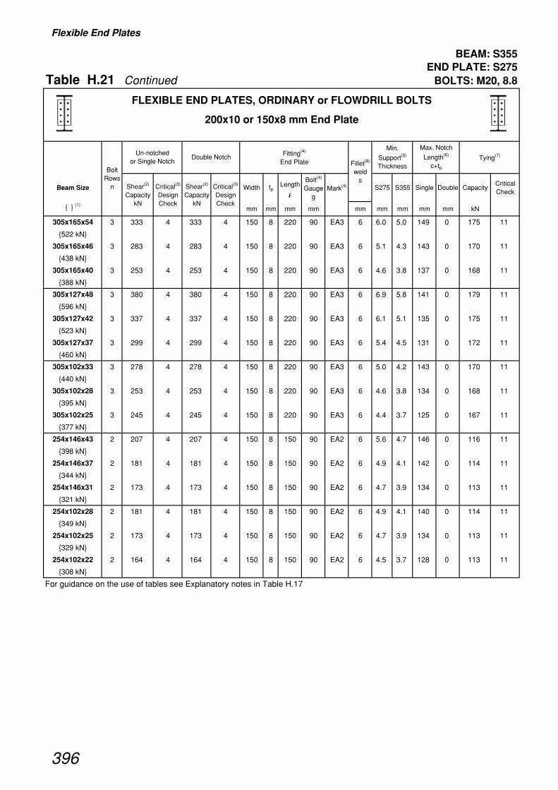
Flexible End Plates
BEAM: S355END PLATE: S275
Table H.21 Continued BOLTS: M20, 8.8
Beam Size Width tpLength
�
Bolt(4)
Gauge g
Mark(4) S275 S355 Single Double CapacityCritical Check
{ } (1)mm mm mm mm mm mm mm mm mm kN
Bolt Rows
n
Tying(7)
Shear(2)
Capacity kN
Fitting(4)
End PlateUn-notched
or Single Notch
Critical(3)
Design Check
Min.
Support(5)
Thickness
Shear(2)
Capacity kN
Critical(3)
Design Check
Max. Notch
Length(6)
c+tpFillet(8)
weld s
Double Notch
FLEXIBLE END PLATES, ORDINARY or FLOWDRILL BOLTS
200x10 or 150x8 mm End Plate
305x165x54 3 333 4 333 4 150 8 220 90 EA3 6 6.0 5.0 149 0 175 11
{522 kN}
305x165x46 3 283 4 283 4 150 8 220 90 EA3 6 5.1 4.3 143 0 170 11
{438 kN}
305x165x40 3 253 4 253 4 150 8 220 90 EA3 6 4.6 3.8 137 0 168 11
{388 kN}
305x127x48 3 380 4 380 4 150 8 220 90 EA3 6 6.9 5.8 141 0 179 11
{596 kN}
305x127x42 3 337 4 337 4 150 8 220 90 EA3 6 6.1 5.1 135 0 175 11
{523 kN}
305x127x37 3 299 4 299 4 150 8 220 90 EA3 6 5.4 4.5 131 0 172 11
{460 kN}
305x102x33 3 278 4 278 4 150 8 220 90 EA3 6 5.0 4.2 143 0 170 11
{440 kN}
305x102x28 3 253 4 253 4 150 8 220 90 EA3 6 4.6 3.8 134 0 168 11
{395 kN}
305x102x25 3 245 4 245 4 150 8 220 90 EA3 6 4.4 3.7 125 0 167 11
{377 kN}
254x146x43 2 207 4 207 4 150 8 150 90 EA2 6 5.6 4.7 146 0 116 11
{398 kN}
254x146x37 2 181 4 181 4 150 8 150 90 EA2 6 4.9 4.1 142 0 114 11
{344 kN}
254x146x31 2 173 4 173 4 150 8 150 90 EA2 6 4.7 3.9 134 0 113 11
{321 kN}
254x102x28 2 181 4 181 4 150 8 150 90 EA2 6 4.9 4.1 140 0 114 11
{349 kN}
254x102x25 2 173 4 173 4 150 8 150 90 EA2 6 4.7 3.9 134 0 113 11
{329 kN}
254x102x22 2 164 4 164 4 150 8 150 90 EA2 6 4.5 3.7 128 0 113 11
{308 kN}
For guidance on the use of tables see Explanatory notes in Table H.17
396
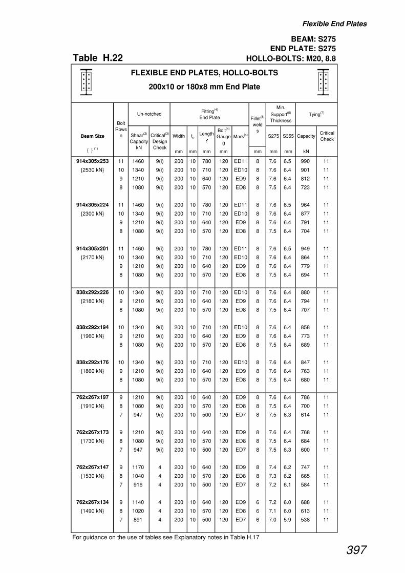
Flexible End Plates
BEAM: S275END PLATE: S275
Table H.22 HOLLO-BOLTS: M20, 8.8
Beam Size Width tpLength
�
Bolt(4)
Gauge g
Mark(4) S275 S355 CapacityCritical Check
{ } (1)mm mm mm mm mm mm mm kN
914x305x253 11 1460 9(i) 200 10 780 120 ED11 8 7.6 6.5 990 11
{2530 kN} 10 1340 9(i) 200 10 710 120 ED10 8 7.6 6.4 901 11
9 1210 9(i) 200 10 640 120 ED9 8 7.6 6.4 812 11
8 1080 9(i) 200 10 570 120 ED8 8 7.5 6.4 723 11
914x305x224 11 1460 9(i) 200 10 780 120 ED11 8 7.6 6.5 964 11
{2300 kN} 10 1340 9(i) 200 10 710 120 ED10 8 7.6 6.4 877 11
9 1210 9(i) 200 10 640 120 ED9 8 7.6 6.4 791 11
8 1080 9(i) 200 10 570 120 ED8 8 7.5 6.4 704 11
914x305x201 11 1460 9(i) 200 10 780 120 ED11 8 7.6 6.5 949 11
{2170 kN} 10 1340 9(i) 200 10 710 120 ED10 8 7.6 6.4 864 11
9 1210 9(i) 200 10 640 120 ED9 8 7.6 6.4 779 11
8 1080 9(i) 200 10 570 120 ED8 8 7.5 6.4 694 11
838x292x226 10 1340 9(i) 200 10 710 120 ED10 8 7.6 6.4 880 11
{2180 kN} 9 1210 9(i) 200 10 640 120 ED9 8 7.6 6.4 794 11
8 1080 9(i) 200 10 570 120 ED8 8 7.5 6.4 707 11
838x292x194 10 1340 9(i) 200 10 710 120 ED10 8 7.6 6.4 858 11
{1960 kN} 9 1210 9(i) 200 10 640 120 ED9 8 7.6 6.4 773 11
8 1080 9(i) 200 10 570 120 ED8 8 7.5 6.4 689 11
838x292x176 10 1340 9(i) 200 10 710 120 ED10 8 7.6 6.4 847 11
{1860 kN} 9 1210 9(i) 200 10 640 120 ED9 8 7.6 6.4 763 11
8 1080 9(i) 200 10 570 120 ED8 8 7.5 6.4 680 11
762x267x197 9 1210 9(i) 200 10 640 120 ED9 8 7.6 6.4 786 11
{1910 kN} 8 1080 9(i) 200 10 570 120 ED8 8 7.5 6.4 700 11
7 947 9(i) 200 10 500 120 ED7 8 7.5 6.3 614 11
762x267x173 9 1210 9(i) 200 10 640 120 ED9 8 7.6 6.4 768 11
{1730 kN} 8 1080 9(i) 200 10 570 120 ED8 8 7.5 6.4 684 11
7 947 9(i) 200 10 500 120 ED7 8 7.5 6.3 600 11
762x267x147 9 1170 4 200 10 640 120 ED9 8 7.4 6.2 747 11
{1530 kN} 8 1040 4 200 10 570 120 ED8 8 7.3 6.2 665 11
7 916 4 200 10 500 120 ED7 8 7.2 6.1 584 11
762x267x134 9 1140 4 200 10 640 120 ED9 6 7.2 6.0 688 11
{1490 kN} 8 1020 4 200 10 570 120 ED8 6 7.1 6.0 613 11
7 891 4 200 10 500 120 ED7 6 7.0 5.9 538 11
For guidance on the use of tables see Explanatory notes in Table H.17
Bolt Rows
n
Tying(7)Fitting(4)
End PlateUn-notched
Min.
Support(5)
Thickness
Shear(2)
Capacity kN
Critical(3)
Design Check
Fillet(8)
weld s
FLEXIBLE END PLATES, HOLLO-BOLTS
200x10 or 180x8 mm End Plate
397
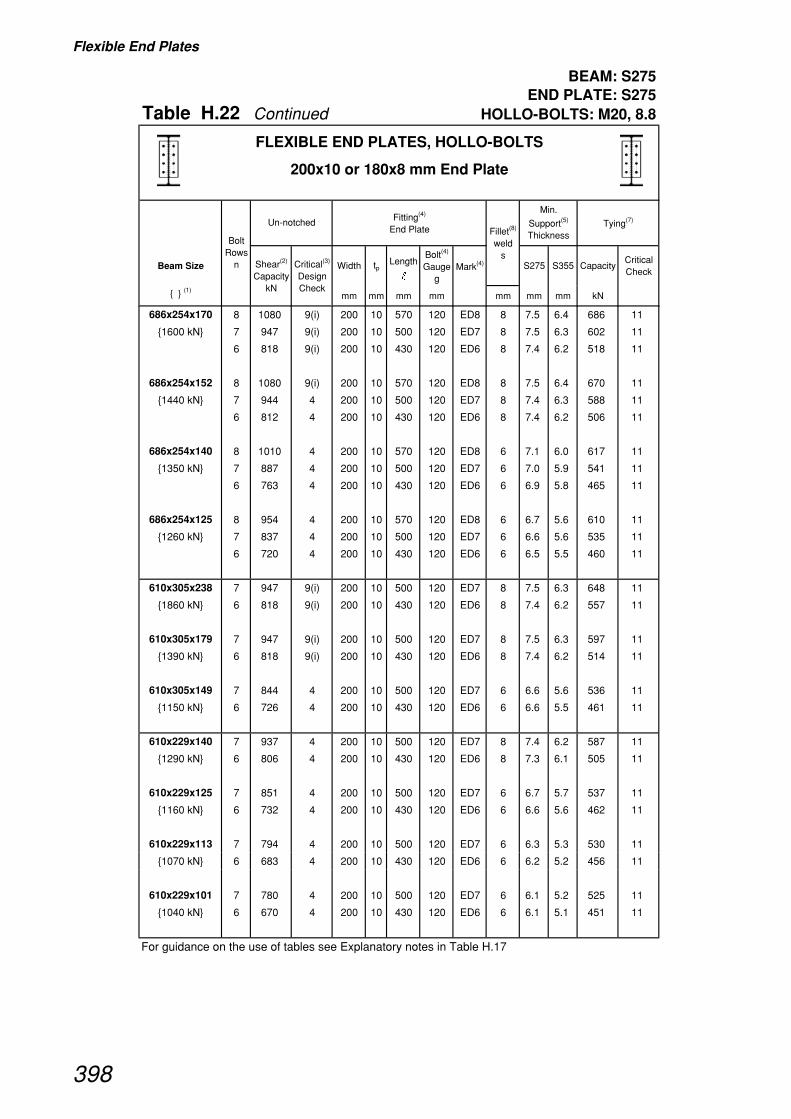
Flexible End Plates
BEAM: S275END PLATE: S275
Table H.22 Continued HOLLO-BOLTS: M20, 8.8
Beam Size Width tpLength
�
Bolt(4)
Gauge g
Mark(4) S275 S355 CapacityCritical Check
{ } (1)mm mm mm mm mm mm mm kN
Bolt Rows
n
Tying(7)Fitting(4)
End PlateUn-notched
Min.
Support(5)
Thickness
Shear(2)
Capacity kN
Critical(3)
Design Check
Fillet(8)
weld s
FLEXIBLE END PLATES, HOLLO-BOLTS
200x10 or 180x8 mm End Plate
686x254x170 8 1080 9(i) 200 10 570 120 ED8 8 7.5 6.4 686 11
{1600 kN} 7 947 9(i) 200 10 500 120 ED7 8 7.5 6.3 602 11
6 818 9(i) 200 10 430 120 ED6 8 7.4 6.2 518 11
686x254x152 8 1080 9(i) 200 10 570 120 ED8 8 7.5 6.4 670 11
{1440 kN} 7 944 4 200 10 500 120 ED7 8 7.4 6.3 588 11
6 812 4 200 10 430 120 ED6 8 7.4 6.2 506 11
686x254x140 8 1010 4 200 10 570 120 ED8 6 7.1 6.0 617 11
{1350 kN} 7 887 4 200 10 500 120 ED7 6 7.0 5.9 541 11
6 763 4 200 10 430 120 ED6 6 6.9 5.8 465 11
686x254x125 8 954 4 200 10 570 120 ED8 6 6.7 5.6 610 11
{1260 kN} 7 837 4 200 10 500 120 ED7 6 6.6 5.6 535 11
6 720 4 200 10 430 120 ED6 6 6.5 5.5 460 11
610x305x238 7 947 9(i) 200 10 500 120 ED7 8 7.5 6.3 648 11
{1860 kN} 6 818 9(i) 200 10 430 120 ED6 8 7.4 6.2 557 11
610x305x179 7 947 9(i) 200 10 500 120 ED7 8 7.5 6.3 597 11
{1390 kN} 6 818 9(i) 200 10 430 120 ED6 8 7.4 6.2 514 11
610x305x149 7 844 4 200 10 500 120 ED7 6 6.6 5.6 536 11
{1150 kN} 6 726 4 200 10 430 120 ED6 6 6.6 5.5 461 11
610x229x140 7 937 4 200 10 500 120 ED7 8 7.4 6.2 587 11
{1290 kN} 6 806 4 200 10 430 120 ED6 8 7.3 6.1 505 11
610x229x125 7 851 4 200 10 500 120 ED7 6 6.7 5.7 537 11
{1160 kN} 6 732 4 200 10 430 120 ED6 6 6.6 5.6 462 11
610x229x113 7 794 4 200 10 500 120 ED7 6 6.3 5.3 530 11
{1070 kN} 6 683 4 200 10 430 120 ED6 6 6.2 5.2 456 11
610x229x101 7 780 4 200 10 500 120 ED7 6 6.1 5.2 525 11
{1040 kN} 6 670 4 200 10 430 120 ED6 6 6.1 5.1 451 11
For guidance on the use of tables see Explanatory notes in Table H.17
398

Flexible End Plates
BEAM: S275END PLATE: S275
Table H.22 Continued HOLLO-BOLTS: M20, 8.8
Beam Size Width tpLength
�
Bolt(4)
Gauge g
Mark(4) S275 S355 CapacityCritical Check
{ } (1)mm mm mm mm mm mm mm kN
Bolt Rows
n
Tying(7)Fitting(4)
End PlateUn-notched
Min.
Support(5)
Thickness
Shear(2)
Capacity kN
Critical(3)
Design Check
Fillet(8)
weld s
FLEXIBLE END PLATES, HOLLO-BOLTS
200x10 or 180x8 mm End Plate
533x210x122 6 781 4 200 10 430 120 ED6 8 7.1 6.0 501 11
{1100 kN} 5 654 4 200 10 360 120 ED5 8 7.1 5.9 419 11
533x210x109 6 714 4 200 10 430 120 ED6 6 6.5 5.4 459 11
{995 kN} 5 598 4 200 10 360 120 ED5 6 6.5 5.4 385 11
533x210x101 6 665 4 200 10 430 120 ED6 6 6.0 5.1 454 11
{922 kN} 5 556 4 200 10 360 120 ED5 6 6.0 5.1 380 11
533x210x92 6 645 4 200 10 430 120 ED6 6 5.8 4.9 448 11
{888 kN} 5 540 4 200 10 360 120 ED5 6 5.9 4.9 375 11
533x210x82 6 613 4 200 10 430 120 ED6 6 5.6 4.7 445 11
{837 kN} 5 513 4 200 10 360 120 ED5 6 5.6 4.7 372 11
457x191x98 5 551 9(i) 180 8 360 90 EC5 6 6.3 5.3 478 11
{847 kN} 4 447 9(i) 180 8 290 90 EC4 6 6.2 5.3 385 11
457x191x89 5 541 4 180 8 360 90 EC5 6 6.2 5.2 465 11
{774 kN} 4 436 4 180 8 290 90 EC4 6 6.1 5.1 375 11
457x191x82 5 529 4 180 8 360 90 EC5 6 6.0 5.1 457 11
{751 kN} 4 426 4 180 8 290 90 EC4 6 6.0 5.0 368 11
457x191x74 5 481 4 180 8 360 90 EC5 6 5.5 4.6 445 11
{679 kN} 4 388 4 180 8 290 90 EC4 6 5.4 4.6 358 11
457x191x67 5 454 4 180 8 360 90 EC5 6 5.2 4.4 438 11
{636 kN} 4 366 4 180 8 290 90 EC4 6 5.1 4.3 353 11
For guidance on the use of tables see Explanatory notes in Table H.17
399

Flexible End Plates
BEAM: S275END PLATE: S275
Table H.22 Continued HOLLO-BOLTS: M20, 8.8
Beam Size Width tpLength
�
Bolt(4)
Gauge g
Mark(4) S275 S355 CapacityCritical Check
{ } (1)mm mm mm mm mm mm mm kN
Bolt Rows
n
Tying(7)Fitting(4)
End PlateUn-notched
Min.
Support(5)
Thickness
Shear(2)
Capacity kN
Critical(3)
Design Check
Fillet(8)
weld s
FLEXIBLE END PLATES, HOLLO-BOLTS
200x10 or 180x8 mm End Plate
457x152x82 5 541 4 180 8 360 90 EC5 6 6.2 5.2 465 11
{778 kN} 4 436 4 180 8 290 90 EC4 6 6.1 5.1 375 11
457x152x74 5 495 4 180 8 360 90 EC5 6 5.6 4.8 453 11
{705 kN} 4 398 4 180 8 290 90 EC4 6 5.6 4.7 365 11
457x152x67 5 481 4 180 8 360 90 EC5 6 5.5 4.6 445 11
{680 kN} 4 388 4 180 8 290 90 EC4 6 5.4 4.6 358 11
457x152x60 5 433 4 180 8 360 90 EC5 6 4.9 4.2 433 11
{608 kN} 4 349 4 180 8 290 90 EC4 6 4.9 4.1 349 11
457x152x52 5 406 4 180 8 360 90 EC5 6 4.6 3.9 427 11
{564 kN} 4 327 4 180 8 290 90 EC4 6 4.6 3.9 344 11
406x178x74 4 409 4 180 8 290 90 EC4 6 5.7 4.8 363 11
{647 kN}
406x178x67 4 379 4 180 8 290 90 EC4 6 5.3 4.5 356 11
{594 kN}
406x178x60 4 340 4 180 8 290 90 EC4 6 4.8 4.0 347 11
{530 kN}
406x178x54 4 332 4 180 8 290 90 EC4 6 4.6 3.9 345 11
{512 kN}
406x140x46 4 293 4 180 8 290 90 EC4 6 4.1 3.5 336 11
{452 kN}
406x140x39 4 276 4 180 8 290 90 EC4 6 3.8 3.3 333 11
{420 kN}
356x171x67 3 297 4 180 8 220 90 EC3 6 5.4 4.5 272 11
{546 kN}
356x171x57 3 265 4 180 8 220 90 EC3 6 4.8 4.0 265 11
{478 kN}
356x171x51 3 242 4 180 8 220 90 EC3 6 4.4 3.7 259 11
{433 kN}
356x171x45 3 229 4 180 8 220 90 EC3 6 4.1 3.5 257 11
{406 kN}
356x127x39 3 216 4 180 8 220 90 EC3 6 3.9 3.3 254 11
{385 kN}
356x127x33 3 196 4 180 8 220 90 EC3 6 3.6 3.0 250 11
{346 kN}
For guidance on the use of tables see Explanatory notes in Table H.17
400

Flexible End Plates
BEAM: S275END PLATE: S275
Table H.22 Continued HOLLO-BOLTS: M20, 8.8
Beam Size Width tpLength
�
Bolt(4)
Gauge g
Mark(4) S275 S355 CapacityCritical Check
{ } (1)mm mm mm mm mm mm mm kN
Bolt Rows
n
Tying(7)Fitting(4)
End PlateUn-notched
Min.
Support(5)
Thickness
Shear(2)
Capacity kN
Critical(3)
Design Check
Fillet(8)
weld s
FLEXIBLE END PLATES, HOLLO-BOLTS
200x10 or 180x8 mm End Plate
305x165x54 3 258 4 180 8 220 90 EC3 6 4.7 3.9 263 11
{405 kN}
305x165x46 3 219 4 180 8 220 90 EC3 6 4.0 3.3 254 11
{339 kN}
305x165x40 3 196 4 180 8 220 90 EC3 6 3.6 3.0 250 11
{300 kN}
305x127x48 3 294 4 180 8 220 90 EC3 6 5.3 4.5 272 11
{462 kN}
305x127x42 3 261 4 180 8 220 90 EC3 6 4.7 4.0 264 11
{406 kN}
305x127x37 3 232 4 180 8 220 90 EC3 6 4.2 3.5 257 11
{357 kN}
305x102x33 3 216 4 180 8 220 90 EC3 6 3.9 3.3 254 11
{341 kN}
305x102x28 3 196 4 180 8 220 90 EC3 6 3.6 3.0 250 11
{306 kN}
305x102x25 3 189 4 180 8 220 90 EC3 6 3.4 2.9 248 11
{292 kN}
254x146x43 2 160 4 180 8 150 90 EC2 6 4.4 3.6 176 11
{308 kN}
254x146x37 2 140 4 180 8 150 90 EC2 6 3.8 3.2 172 11
{266 kN}
254x146x31 2 134 4 180 8 150 90 EC2 6 3.6 3.0 170 11
{249 kN}
254x102x28 2 140 4 180 8 150 90 EC2 6 3.8 3.2 172 11
{271 kN}
254x102x25 2 134 4 180 8 150 90 EC2 6 3.6 3.0 170 11
{255 kN}
254x102x22 2 127 4 180 8 150 90 EC2 6 3.5 2.9 169 11
{239 kN}
For guidance on the use of tables see Explanatory notes in Table H.17
401

Flexible End Plates
BEAM: S355END PLATE: S275
Table H.23 HOLLO-BOLTS: M20, 8.8
Beam Size Width tpLength
�
Bolt(4)
Gauge g
Mark(4) S275 S355 CapacityCritical Check
{ } (1)mm mm mm mm mm mm mm kN
914x305x253 11 1460 9(i) 200 10 780 120 ED11 8 7.6 6.5 990 11
{3290 kN} 10 1340 9(i) 200 10 710 120 ED10 8 7.6 6.4 901 11
9 1210 9(i) 200 10 640 120 ED9 8 7.6 6.4 812 11
8 1080 9(i) 200 10 570 120 ED8 8 7.5 6.4 723 11
914x305x224 11 1460 9(i) 200 10 780 120 ED11 8 7.6 6.5 964 11
{3000 kN} 10 1340 9(i) 200 10 710 120 ED10 8 7.6 6.4 877 11
9 1210 9(i) 200 10 640 120 ED9 8 7.6 6.4 791 11
8 1080 9(i) 200 10 570 120 ED8 8 7.5 6.4 704 11
914x305x201 11 1460 9(i) 200 10 780 120 ED11 8 7.6 6.5 949 11
{2820 kN} 10 1340 9(i) 200 10 710 120 ED10 8 7.6 6.4 864 11
9 1210 9(i) 200 10 640 120 ED9 8 7.6 6.4 779 11
8 1080 9(i) 200 10 570 120 ED8 8 7.5 6.4 694 11
838x292x226 10 1340 9(i) 200 10 710 120 ED10 8 7.6 6.4 880 11
{2840 kN} 9 1210 9(i) 200 10 640 120 ED9 8 7.6 6.4 794 11
8 1080 9(i) 200 10 570 120 ED8 8 7.5 6.4 707 11
838x292x194 10 1340 9(i) 200 10 710 120 ED10 8 7.6 6.4 858 11
{2560 kN} 9 1210 9(i) 200 10 640 120 ED9 8 7.6 6.4 773 11
8 1080 9(i) 200 10 570 120 ED8 8 7.5 6.4 689 11
838x292x176 10 1340 9(i) 200 10 710 120 ED10 8 7.6 6.4 847 11
{2420 kN} 9 1210 9(i) 200 10 640 120 ED9 8 7.6 6.4 763 11
8 1080 9(i) 200 10 570 120 ED8 8 7.5 6.4 680 11
762x267x197 9 1210 9(i) 200 10 640 120 ED9 8 7.6 6.4 786 11
{2490 kN} 8 1080 9(i) 200 10 570 120 ED8 8 7.5 6.4 700 11
7 947 9(i) 200 10 500 120 ED7 8 7.5 6.3 614 11
762x267x173 9 1210 9(i) 200 10 640 120 ED9 8 7.6 6.4 768 11
{2260 kN} 8 1080 9(i) 200 10 570 120 ED8 8 7.5 6.4 684 11
7 947 9(i) 200 10 500 120 ED7 8 7.5 6.3 600 11
762x267x147 9 1210 9(i) 200 10 640 120 ED9 8 7.6 6.4 747 11
{2000 kN} 8 1080 9(i) 200 10 570 120 ED8 8 7.5 6.4 665 11
7 947 9(i) 200 10 500 120 ED7 8 7.5 6.3 584 11
762x267x134 9 1210 9(i) 200 10 640 120 ED9 8 7.6 6.4 737 11
{1920 kN} 8 1080 9(i) 200 10 570 120 ED8 8 7.5 6.4 656 11
7 947 9(i) 200 10 500 120 ED7 8 7.5 6.3 575 11
For guidance on the use of tables see Explanatory notes in Table H.17
Bolt Rows
n
Tying(7)Fitting(4)
End PlateUn-notched
Min.
Support(5)
Thickness
Shear(2)
Capacity kN
Critical(3)
Design Check
Fillet(8)
weld s
FLEXIBLE END PLATES, HOLLO-BOLTS
200x10 or 180x8 mm End Plate
402

Flexible End Plates
BEAM: S355END PLATE: S275
Table H.23 Continued HOLLO-BOLTS: M20, 8.8
Beam Size Width tpLength
�
Bolt(4)
Gauge g
Mark(4) S275 S355 CapacityCritical Check
{ } (1)mm mm mm mm mm mm mm kN
Bolt Rows
n
Tying(7)Fitting(4)
End PlateUn-notched
Min.
Support(5)
Thickness
Shear(2)
Capacity kN
Critical(3)
Design Check
Fillet(8)
weld s
FLEXIBLE END PLATES, HOLLO-BOLTS
200x10 or 180x8 mm End Plate
686x254x170 8 1080 9(i) 200 10 570 120 ED8 8 7.5 6.4 686 11
{2080 kN} 7 947 9(i) 200 10 500 120 ED7 8 7.5 6.3 602 11
6 818 9(i) 200 10 430 120 ED6 8 7.4 6.2 518 11
686x254x152 8 1080 9(i) 200 10 570 120 ED8 8 7.5 6.4 670 11
{1880 kN} 7 947 9(i) 200 10 500 120 ED7 8 7.5 6.3 588 11
6 818 9(i) 200 10 430 120 ED6 8 7.4 6.2 506 11
686x254x140 8 1080 9(i) 200 10 570 120 ED8 8 7.5 6.4 661 11
{1750 kN} 7 947 9(i) 200 10 500 120 ED7 8 7.5 6.3 580 11
6 818 9(i) 200 10 430 120 ED6 8 7.4 6.2 498 11
686x254x125 8 1080 9(i) 200 10 570 120 ED8 8 7.5 6.4 653 11
{1640 kN} 7 947 9(i) 200 10 500 120 ED7 8 7.5 6.3 572 11
6 818 9(i) 200 10 430 120 ED6 8 7.4 6.2 492 11
610x305x238 7 947 9(i) 200 10 500 120 ED7 8 7.5 6.3 648 11
{2420 kN} 6 818 9(i) 200 10 430 120 ED6 8 7.4 6.2 557 11
610x305x179 7 947 9(i) 200 10 500 120 ED7 8 7.5 6.3 597 11
{1810 kN} 6 818 9(i) 200 10 430 120 ED6 8 7.4 6.2 514 11
610x305x149 7 947 9(i) 200 10 500 120 ED7 8 7.5 6.3 573 11
{1500 kN} 6 818 9(i) 200 10 430 120 ED6 8 7.4 6.2 493 11
610x229x140 7 947 9(i) 200 10 500 120 ED7 8 7.5 6.3 587 11
{1670 kN} 6 818 9(i) 200 10 430 120 ED6 8 7.4 6.2 505 11
610x229x125 7 947 9(i) 200 10 500 120 ED7 8 7.5 6.3 574 11
{1510 kN} 6 818 9(i) 200 10 430 120 ED6 8 7.4 6.2 494 11
610x229x113 7 947 9(i) 200 10 500 120 ED7 8 7.5 6.3 566 11
{1400 kN} 6 818 9(i) 200 10 430 120 ED6 8 7.4 6.2 487 11
610x229x101 7 947 9(i) 200 10 500 120 ED7 8 7.5 6.3 561 11
{1350 kN} 6 818 9(i) 200 10 430 120 ED6 8 7.4 6.2 482 11
For guidance on the use of tables see Explanatory notes in Table H.17
403

Flexible End Plates
BEAM: S355END PLATE: S275
Table H.23 Continued HOLLO-BOLTS: M20, 8.8
Beam Size Width tpLength
�
Bolt(4)
Gauge g
Mark(4) S275 S355 CapacityCritical Check
{ } (1)mm mm mm mm mm mm mm kN
Bolt Rows
n
Tying(7)Fitting(4)
End PlateUn-notched
Min.
Support(5)
Thickness
Shear(2)
Capacity kN
Critical(3)
Design Check
Fillet(8)
weld s
FLEXIBLE END PLATES, HOLLO-BOLTS
200x10 or 180x8 mm End Plate
533x210x122 6 818 9(i) 200 10 430 120 ED6 8 7.4 6.2 501 11
{1430 kN} 5 688 9(i) 200 10 360 120 ED5 8 7.5 6.3 419 11
533x210x109 6 818 9(i) 200 10 430 120 ED6 8 7.4 6.2 491 11
{1300 kN} 5 688 9(i) 200 10 360 120 ED5 8 7.5 6.3 411 11
533x210x101 6 818 9(i) 200 10 430 120 ED6 8 7.4 6.2 485 11
{1200 kN} 5 688 9(i) 200 10 360 120 ED5 8 7.5 6.3 406 11
533x210x92 6 818 9(i) 200 10 430 120 ED6 8 7.4 6.2 479 11
{1150 kN} 5 688 9(i) 200 10 360 120 ED5 8 7.5 6.3 401 11
533x210x82 6 791 4 200 10 430 120 ED6 8 7.2 6.0 475 11
{1080 kN} 5 663 4 200 10 360 120 ED5 8 7.2 6.0 398 11
457x191x98 5 551 9(i) 180 8 360 90 EC5 6 6.3 5.3 478 11
{1100 kN} 4 447 9(i) 180 8 290 90 EC4 6 6.2 5.3 385 11
457x191x89 5 551 9(i) 180 8 360 90 EC5 6 6.3 5.3 465 11
{1010 kN} 4 447 9(i) 180 8 290 90 EC4 6 6.2 5.3 375 11
457x191x82 5 551 9(i) 180 8 360 90 EC5 6 6.3 5.3 457 11
{970 kN} 4 447 9(i) 180 8 290 90 EC4 6 6.2 5.3 368 11
457x191x74 5 551 9(i) 180 8 360 90 EC5 6 6.3 5.3 445 11
{876 kN} 4 447 9(i) 180 8 290 90 EC4 6 6.2 5.3 358 11
457x191x67 5 551 9(i) 180 8 360 90 EC5 6 6.3 5.3 438 11
{821 kN} 4 447 9(i) 180 8 290 90 EC4 6 6.2 5.3 353 11
For guidance on the use of tables see Explanatory notes in Table H.17
404

Flexible End Plates
BEAM: S355END PLATE: S275
Table H.23 Continued HOLLO-BOLTS: M20, 8.8
Beam Size Width tpLength
�
Bolt(4)
Gauge g
Mark(4) S275 S355 CapacityCritical Check
{ } (1)mm mm mm mm mm mm mm kN
Bolt Rows
n
Tying(7)Fitting(4)
End PlateUn-notched
Min.
Support(5)
Thickness
Shear(2)
Capacity kN
Critical(3)
Design Check
Fillet(8)
weld s
FLEXIBLE END PLATES, HOLLO-BOLTS
200x10 or 180x8 mm End Plate
457x152x82 5 551 9(i) 180 8 360 90 EC5 6 6.3 5.3 465 11
{1010 kN} 4 447 9(i) 180 8 290 90 EC4 6 6.2 5.3 375 11
457x152x74 5 551 9(i) 180 8 360 90 EC5 6 6.3 5.3 453 11
{918 kN} 4 447 9(i) 180 8 290 90 EC4 6 6.2 5.3 365 11
457x152x67 5 551 9(i) 180 8 360 90 EC5 6 6.3 5.3 445 11
{878 kN} 4 447 9(i) 180 8 290 90 EC4 6 6.2 5.3 358 11
457x152x60 5 551 9(i) 180 8 360 90 EC5 6 6.3 5.3 433 11
{784 kN} 4 447 9(i) 180 8 290 90 EC4 6 6.2 5.3 349 11
457x152x52 5 524 4 180 8 360 90 EC5 6 6.0 5.0 427 11
{728 kN} 4 423 4 180 8 290 90 EC4 6 5.9 5.0 344 11
406x178x74 4 447 9(i) 180 8 290 90 EC4 6 6.2 5.3 363 11
{835 kN}
406x178x67 4 447 9(i) 180 8 290 90 EC4 6 6.2 5.3 356 11
{767 kN}
406x178x60 4 439 4 180 8 290 90 EC4 6 6.1 5.2 347 11
{684 kN}
406x178x54 4 428 4 180 8 290 90 EC4 6 6.0 5.1 345 11
{660 kN}
406x140x46 4 378 4 180 8 290 90 EC4 6 5.3 4.5 336 11
{584 kN}
406x140x39 4 356 4 180 8 290 90 EC4 6 5.0 4.2 333 11
{543 kN}
356x171x67 3 344 9(i) 180 8 220 90 EC3 6 6.2 5.2 272 11
{704 kN}
356x171x57 3 342 4 180 8 220 90 EC3 6 6.2 5.2 265 11
{618 kN}
356x171x51 3 312 4 180 8 220 90 EC3 6 5.7 4.8 259 11
{560 kN}
356x171x45 3 295 4 180 8 220 90 EC3 6 5.3 4.5 257 11
{524 kN}
356x127x39 3 278 4 180 8 220 90 EC3 6 5.0 4.2 254 11
{497 kN}
356x127x33 3 253 4 180 8 220 90 EC3 6 4.6 3.9 250 11
{446 kN}
For guidance on the use of tables see Explanatory notes in Table H.17
405

Flexible End Plates
BEAM: S355END PLATE: S275
Table H.23 Continued HOLLO-BOLTS: M20, 8.8
Beam Size Width tpLength
�
Bolt(4)
Gauge g
Mark(4) S275 S355 CapacityCritical Check
{ } (1)mm mm mm mm mm mm mm kN
Bolt Rows
n
Tying(7)Fitting(4)
End PlateUn-notched
Min.
Support(5)
Thickness
Shear(2)
Capacity kN
Critical(3)
Design Check
Fillet(8)
weld s
FLEXIBLE END PLATES, HOLLO-BOLTS
200x10 or 180x8 mm End Plate
305x165x54 3 333 4 180 8 220 90 EC3 6 6.0 5.1 263 11
{522 kN}
305x165x46 3 283 4 180 8 220 90 EC3 6 5.1 4.3 254 11
{438 kN}
305x165x40 3 253 4 180 8 220 90 EC3 6 4.6 3.9 250 11
{388 kN}
305x127x48 3 344 9(i) 180 8 220 90 EC3 6 6.2 5.2 272 11
{596 kN}
305x127x42 3 337 4 180 8 220 90 EC3 6 6.1 5.1 264 11
{523 kN}
305x127x37 3 299 4 180 8 220 90 EC3 6 5.4 4.6 257 11
{460 kN}
305x102x33 3 278 4 180 8 220 90 EC3 6 5.0 4.2 254 11
{440 kN}
305x102x28 3 253 4 180 8 220 90 EC3 6 4.6 3.9 250 11
{395 kN}
305x102x25 3 245 4 180 8 220 90 EC3 6 4.4 3.7 248 11
{377 kN}
254x146x43 2 207 4 180 8 150 90 EC2 6 5.6 4.7 176 11
{398 kN}
254x146x37 2 181 4 180 8 150 90 EC2 6 4.9 4.1 172 11
{344 kN}
254x146x31 2 173 4 180 8 150 90 EC2 6 4.7 3.9 170 11
{321 kN}
254x102x28 2 181 4 180 8 150 90 EC2 6 4.9 4.1 172 11
{349 kN}
254x102x25 2 173 4 180 8 150 90 EC2 6 4.7 3.9 170 11
{329 kN}
254x102x22 2 164 4 180 8 150 90 EC2 6 4.5 3.7 169 11
{308 kN}
For guidance on the use of tables see Explanatory notes in Table H.17
406
Fin Plates
407
Table H.24
Explanatory notes - FIN PLATES
Use of Capacity Tables
The following notes refer to the suffix numbers given at the top of the column descriptions for Tables H.27 to H.30.
The check numbers refer to those listed in Table H.26 and described in Section 6.5 Design procedures.
The capacity tables are based on the standard details given in Table H.25.
All universal beam sections which are suitable for the minimum standard fitting size and the standard notch sizeare shown in the tables (i.e. if T + r > 50 mm, section is not included).
SHADED PORTION OF TABLES:
Connections for beams in the shaded portion of the tables may only be used when:
• the supported beam span/depth ratio ≤ 20
• the gap between the supported beam end and the supporting element = 20 mm
• the maximum number of bolt rows = 8 (i.e. (n – 1)p = 490 mm, which does not exceed the limit of 530 mm).
(1) SHEAR CAPACITY OF THE BEAM
The value given in { } is the shear capacity of the beam, given by 0.6pytwD.
(2) SHEAR CAPACITY OF THE CONNECTION
This is the critical value of the design checks for the 'supported beam side' of the connection. i.e. theminimum capacity from CHECKS 2, 3(i), 3(ii), 4(i), 4(ii) and 8.
(3) CRITICAL DESIGN CHECK
The check which gives the critical value of shear capacity. See Table H.26 for the description of the checks.
(4) FITTINGS
The length and type of Standard Fin Plate fittings. See Tables H.1 and H.4 for details
(5) MINIMUM SUPPORT THICKNESS
This is the minimum thickness of supporting column or beam element, that is needed to carry the givenSHEAR CAPACITY (Un-notched or Single Notched) of the connection. It is derived fromCHECK 10.
For a symmetrical two sided connection, the minimum support thickness would be twice the tabulated value.
(6) MAXIMUM NOTCH LENGTH ( C + T1 )
These are maximum lengths of notches for single and double notched beams that can be accommodatedif the beam is to carry the tabulated corresponding SHEAR CAPACITY of the connection.
It is assumed that the beam is fully restrained against lateral torsional buckling, and the notched lengthsare derived from CHECKS 5 and 6.
To provide a simple check for double notched beams, it has been assumed that the remaining web depth,'y' (see Table H.25) is the same as the end plate length.
* Indicates that the condition from CHECK 6, i.e. dc2 ≤ D/5 is not satisfied.
(7) TYING CAPACITY
This is the critical value of the design checks for the 'supported beam' side of the connection,i.e. the minimum capacity from CHECKS 11(i), 11(ii), 12(i) and12(ii).
In CHECK 12 the supported beam is assumed to be a double notched member.
Separate checks will have to be carried out on the supporting member. (See CHECKS 14, 15 and 16).

Fin Plates
408
t1 = 10 mm for supported beams ≤ 610 x 305 UB
t1 = 20 mm for supported beams > 610 x 305 UB
Table H.25
FIN PLATES
Standard details used in Capacity Tables
Note: See Tables H.1 and H.4 Standard Fittings, Marks and details for Fin Plates
l
l
l
t 1
t 1
t 1 t 1
y
Top of beam to first row of bolts = 90mm
C
t 1
End projection, t 1End projection, t 1
to first rowof bolts = 90mm
50
40
40
of bolts = 90mmto first rowTop of beam
40
40
50
50
40
40
8
8
8
50 or 60 (See Table H.4)
Bolts M20 grade 8.8
Bolts M20 grade 8.8
Bolts M20 grade 8.8
C
n rows of bolts at vertical
pitch, 70
Note: For simplicity the capacity tables assume that the remaining depth of beam web, y(mm), is equal to the fin plate length, l (mm).
n rows of bolts at vertical
pitch, 70
n rows of bolts at vertical
pitch, 70
Top of beam
50 or 60 (See Table H.4) 50 or 60 (See Table H.4)
50 or 60 (See Table H.4)
50 or 60 (See Table H.4)
50 or 60 (See Table H.4)
50 or 60 (See Table H.4)
50 or 60 (See Table H.4)
50 or 60 (See Table H.4)
DOUBLE NOTCHED BEAM
UN-NOTCHED BEAM
SINGLE NOTCHED BEAM

Fin Plates
409
Table H.26
FIN PLATESCritical Check Description List
Check Number Description
2 Capacity of bolt group
3(i) Shear capacity of fin plate
3(ii) Shear and bending interaction capacity of fin plate
4(i) Shear capacity of supported beam at the connection
4(ii) Shear and bending interaction capacity of supported beam at the2nd bolt line connection
8 Capacity of fillet weld
11(i) Tension capacity of fin plate
11(ii) Bearing capacity of fin plate
12(i) Tension capacity of supported beam web at the connection
12(ii) Bearing capacity of supported beam web at the connection
SH
EA
R C
AP
AC
ITY
ST
RU
CT
UR
AL
INT
EG
RIT
Y
Su
pp
ort
ing
S
up
po
rted
mem
ber
sid
e
bea
m s
ide
Note: This table only lists the critical checks.
For a full list of design checks and further information, see Section 6.5.
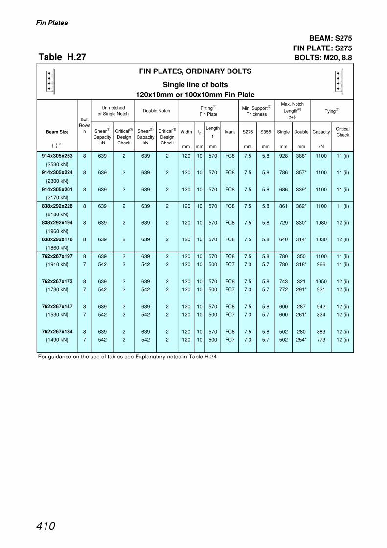
Fin Plates
BEAM: S275 FIN PLATE: S275
Table H.27 BOLTS: M20, 8.8
Beam Size Width tpLength
�Mark S275 S355 Single Double Capacity
Critical Check
{ } (1)mm mm mm mm mm mm mm kN
914x305x253 8 639 2 639 2 120 10 570 FC8 7.5 5.8 928 388* 1100 11 (ii)
{2530 kN}
914x305x224 8 639 2 639 2 120 10 570 FC8 7.5 5.8 786 357* 1100 11 (ii)
{2300 kN}
914x305x201 8 639 2 639 2 120 10 570 FC8 7.5 5.8 686 339* 1100 11 (ii)
{2170 kN}
838x292x226 8 639 2 639 2 120 10 570 FC8 7.5 5.8 861 362* 1100 11 (ii)
{2180 kN}
838x292x194 8 639 2 639 2 120 10 570 FC8 7.5 5.8 729 330* 1080 12 (ii)
{1960 kN}
838x292x176 8 639 2 639 2 120 10 570 FC8 7.5 5.8 640 314* 1030 12 (ii)
{1860 kN}
762x267x197 8 639 2 639 2 120 10 570 FC8 7.5 5.8 780 350 1100 11 (ii)
{1910 kN} 7 542 2 542 2 120 10 500 FC7 7.3 5.7 780 318* 966 11 (ii)
762x267x173 8 639 2 639 2 120 10 570 FC8 7.5 5.8 743 321 1050 12 (ii)
{1730 kN} 7 542 2 542 2 120 10 500 FC7 7.3 5.7 772 291* 921 12 (ii)
762x267x147 8 639 2 639 2 120 10 570 FC8 7.5 5.8 600 287 942 12 (ii)
{1530 kN} 7 542 2 542 2 120 10 500 FC7 7.3 5.7 600 261* 824 12 (ii)
762x267x134 8 639 2 639 2 120 10 570 FC8 7.5 5.8 502 280 883 12 (ii)
{1490 kN} 7 542 2 542 2 120 10 500 FC7 7.3 5.7 502 254* 773 12 (ii)
For guidance on the use of tables see Explanatory notes in Table H.24
Un-notched or Single Notch
Critical(3)
Design Check
Critical(3)
Design Check
Max. Notch
Length(6)
c+t1
Shear(2)
Capacity kN
Shear(2)
Capacity kN
Fitting(4)
Fin Plate
FIN PLATES, ORDINARY BOLTS
Single line of bolts120x10mm or 100x10mm Fin Plate
Double Notch Min. Support(5)
ThicknessTying(7)
Bolt Rows
n
410

Fin Plates
BEAM: S275 FIN PLATE: S275
Table H.27 Continued BOLTS: M20, 8.8
Beam Size Width tpLength
�Mark S275 S355 Single Double Capacity
Critical Check
{ } (1)mm mm mm mm mm mm mm kN
Un-notched or Single Notch
Critical(3)
Design Check
Critical(3)
Design Check
Max. Notch
Length(6)
c+t1
Shear(2)
Capacity kN
Shear(2)
Capacity kN
Fitting(4)
Fin Plate
FIN PLATES, ORDINARY BOLTS
Single line of bolts120x10mm or 100x10mm Fin Plate
Double Notch Min. Support(5)
ThicknessTying(7)
Bolt Rows
n
686x254x170 8 639 2 639 2 120 10 570 FC8 7.5 5.8 624 326 1070 12 (ii)
{1600 kN} 7 542 2 542 2 120 10 500 FC7 7.3 5.7 703 296* 934 12 (ii)
6 445 2 445 2 120 10 430 FC6 7.0 5.4 703 266* 800 12 (ii)
686x254x152 8 639 2 639 2 120 10 570 FC8 7.5 5.8 559 296 972 12 (ii)
{1440 kN} 7 542 2 542 2 120 10 500 FC7 7.3 5.7 659 269 850 12 (ii)
6 445 2 445 2 120 10 430 FC6 7.0 5.4 698 242* 729 12 (ii)
686x254x140 8 639 2 639 2 120 10 570 FC8 7.5 5.8 517 278 913 12 (ii)
{1350 kN} 7 542 2 542 2 120 10 500 FC7 7.3 5.7 610 253 799 12 (ii)
6 445 2 445 2 120 10 430 FC6 7.0 5.4 663 228* 684 12 (ii)
686x254x125 8 639 2 639 2 120 10 570 FC8 7.5 5.8 474 263 861 12 (ii)
{1260 kN} 7 542 2 542 2 120 10 500 FC7 7.3 5.7 559 238 753 12 (ii)
6 445 2 445 2 120 10 430 FC6 7.0 5.4 568 215* 646 12 (ii)
610x305x238 7 542 2 542 2 100 10 500 FA7 7.3 5.7 646 375 966 11 (ii)
{1860 kN} 6 445 2 445 2 100 10 430 FA6 7.0 5.4 646 338* 828 11 (ii)
610x305x179 7 542 2 542 2 100 10 500 FA7 7.3 5.7 589 287 908 12 (ii)
{1390 kN} 6 445 2 445 2 100 10 430 FA6 7.0 5.4 630 259* 778 12 (ii)
610x305x149 7 542 2 542 2 100 10 500 FA7 7.3 5.7 483 241 760 12 (ii)
{1150 kN} 6 445 2 445 2 100 10 430 FA6 7.0 5.4 588 217* 651 12 (ii)
610x229x140 7 542 2 542 2 100 10 500 FA7 7.3 5.7 521 267 844 12 (ii)
{1290 kN} 6 445 2 445 2 100 10 430 FA6 7.0 5.4 627 240* 723 12 (ii)
610x229x125 7 542 2 542 2 100 10 500 FA7 7.3 5.7 465 243 766 12 (ii)
{1160 kN} 6 445 2 445 2 100 10 430 FA6 7.0 5.4 567 218* 657 12 (ii)
610x229x113 7 568 2 568 2 100 10 500 FA7 7.6 5.9 406 204 715 12 (ii)
{1070 kN} 6 471 2 471 2 100 10 430 FA6 7.4 5.7 489 193* 613 12 (ii)
610x229x101 7 568 2 568 2 100 10 500 FA7 7.6 5.9 387 195 676 12 (ii)
{1040 kN} 6 471 2 471 2 100 10 430 FA6 7.4 5.7 467 184* 580 12 (ii)
For guidance on the use of tables see Explanatory notes in Table H.24
411

Fin Plates
BEAM: S275 FIN PLATE: S275
Table H.27 Continued BOLTS: M20, 8.8
Beam Size Width tpLength
�Mark S275 S355 Single Double Capacity
Critical Check
{ } (1)mm mm mm mm mm mm mm kN
Un-notched or Single Notch
Critical(3)
Design Check
Critical(3)
Design Check
Max. Notch
Length(6)
c+t1
Shear(2)
Capacity kN
Shear(2)
Capacity kN
Fitting(4)
Fin Plate
FIN PLATES, ORDINARY BOLTS
Single line of bolts120x10mm or 100x10mm Fin Plate
Double Notch Min. Support(5)
ThicknessTying(7)
Bolt Rows
n
533x210x122 6 471 2 471 2 100 10 430 FA6 7.4 5.7 443 220 690 11 (ii)
{1100 kN} 5 374 2 374 2 100 10 360 FA5 7.0 5.4 555 194* 575 11 (ii)
533x210x109 6 471 2 471 2 100 10 430 FA6 7.4 5.7 397 201 640 12 (ii)
{995 kN} 5 374 2 374 2 100 10 360 FA5 7.0 5.4 499 177* 534 12 (ii)
533x210x101 6 471 2 471 2 100 10 430 FA6 7.4 5.7 366 180 596 12 (ii)
{922 kN} 5 374 2 374 2 100 10 360 FA5 7.0 5.4 460 165* 497 12 (ii)
533x210x92 6 471 2 471 2 100 10 430 FA6 7.4 5.7 349 167 558 12 (ii)
{888 kN} 5 374 2 374 2 100 10 360 FA5 7.0 5.4 439 160* 465 12 (ii)
533x210x82 6 452 2 452 2 100 10 430 FA6 7.1 5.5 334 162 530 12 (ii)
{837 kN} 5 359 2 359 2 100 10 360 FA5 6.7 5.2 421 155* 442 12 (ii)
457x191x98 5 374 2 374 2 100 10 360 FA5 7.0 5.4 360 174 524 12 (ii)
{847 kN} 4 279 2 279 2 100 10 290 FA4 6.5 5.0 477 152* 420 12 (ii)
457x191x89 5 374 2 374 2 100 10 360 FA5 7.0 5.4 327 161 483 12 (ii)
{774 kN} 4 279 2 279 2 100 10 290 FA4 6.5 5.0 437 140* 386 12 (ii)
457x191x82 5 371 2 371 2 100 10 360 FA5 6.9 5.4 317 155 455 12 (ii)
{751 kN} 4 277 2 277 2 100 10 290 FA4 6.4 5.0 424 138* 364 12 (ii)
457x191x74 5 337 2 337 2 100 10 360 FA5 6.3 4.9 313 155 414 12 (ii)
{679 kN} 4 251 2 251 2 100 10 290 FA4 5.8 4.5 420 138* 331 12 (ii)
457x191x67 5 318 2 318 2 100 10 360 FA5 6.0 4.6 306 155 391 12 (ii)
{636 kN} 4 237 2 237 2 100 10 290 FA4 5.5 4.3 410 138* 313 12 (ii)
For guidance on the use of tables see Explanatory notes in Table H.24
412

Fin Plates
BEAM: S275 FIN PLATE: S275
Table H.27 Continued BOLTS: M20, 8.8
Beam Size Width tpLength
�Mark S275 S355 Single Double Capacity
Critical Check
{ } (1)mm mm mm mm mm mm mm kN
Un-notched or Single Notch
Critical(3)
Design Check
Critical(3)
Design Check
Max. Notch
Length(6)
c+t1
Shear(2)
Capacity kN
Shear(2)
Capacity kN
Fitting(4)
Fin Plate
FIN PLATES, ORDINARY BOLTS
Single line of bolts120x10mm or 100x10mm Fin Plate
Double Notch Min. Support(5)
ThicknessTying(7)
Bolt Rows
n
457x152x82 5 374 2 374 2 100 10 360 FA5 7.0 5.4 322 161 483 12 (ii)
{778 kN} 4 279 2 279 2 100 10 290 FA4 6.5 5.0 431 140* 386 12 (ii)
457x152x74 5 359 2 359 2 100 10 360 FA5 6.7 5.2 301 142 442 12 (ii)
{705 kN} 4 268 2 268 2 100 10 290 FA4 6.2 4.8 404 133* 353 12 (ii)
457x152x67 5 337 2 337 2 100 10 360 FA5 6.3 4.9 305 155 414 12 (ii)
{680 kN} 4 251 2 251 2 100 10 290 FA4 5.8 4.5 409 138* 331 12 (ii)
457x152x60 5 303 2 303 2 100 10 360 FA5 5.7 4.4 301 155 373 12 (ii)
{608 kN} 4 226 2 226 2 100 10 290 FA4 5.3 4.1 403 138* 298 12 (ii)
457x152x52 5 284 2 284 2 100 10 360 FA5 5.3 4.1 289 155 350 12 (ii)
{564 kN} 4 212 2 212 2 100 10 290 FA4 4.9 3.8 357 138* 280 12 (ii)
406x178x74 4 265 2 265 2 100 10 290 FA4 6.2 4.8 336 138 350 12 (ii)
{647 kN}
406x178x67 4 246 2 246 2 100 10 290 FA4 5.7 4.4 329 138 324 12 (ii)
{594 kN}
406x178x60 4 221 2 221 2 100 10 290 FA4 5.1 4.0 325 138 291 12 (ii)
{530 kN}
406x178x54 4 215 2 215 2 100 10 290 FA4 5.0 3.9 314 138 283 12 (ii)
{512 kN}
406x140x46 4 190 2 190 2 100 10 290 FA4 4.4 3.4 311 138 250 12 (ii)
{452 kN}
406x140x39 4 179 2 179 2 100 10 290 FA4 4.2 3.2 275 138 236 12 (ii)
{420 kN}
356x171x67 3 171 2 171 2 100 10 220 FA3 5.2 4.1 373 118* 251 12 (ii)
{546 kN}
356x171x57 3 153 2 153 2 100 10 220 FA3 4.7 3.6 364 118* 224 12 (ii)
{478 kN}
356x171x51 3 139 2 139 2 100 10 220 FA3 4.3 3.3 357 118* 204 12 (ii)
{433 kN}
356x171x45 3 132 2 132 2 100 10 220 FA3 4.0 3.1 345 118* 193 12 (ii)
{406 kN}
356x127x39 3 124 2 124 2 100 10 220 FA3 3.8 2.9 340 118* 182 12 (ii)
{385 kN}
356x127x33 3 113 2 113 2 100 10 220 FA3 3.5 2.7 294 118* 166 12 (ii)
{346 kN}
For guidance on the use of tables see Explanatory notes in Table H.24
413
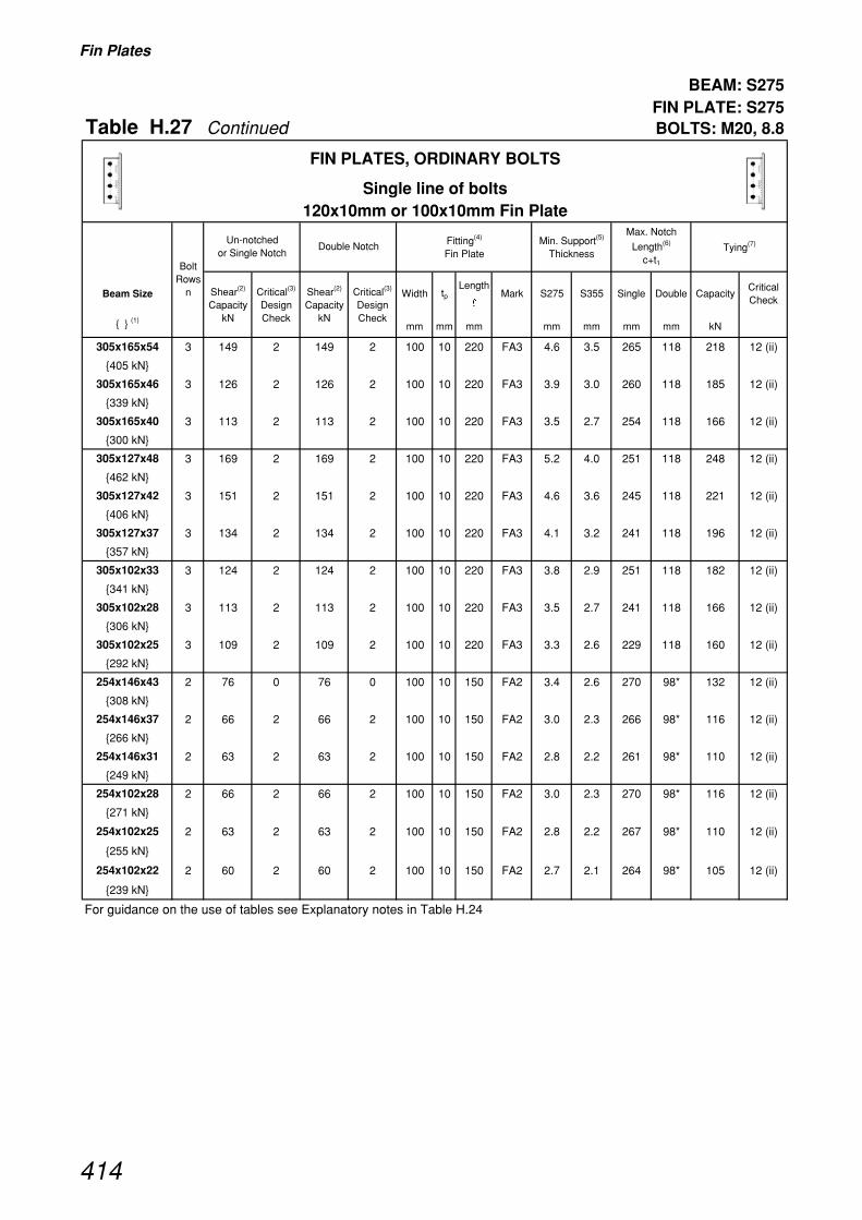
Fin Plates
BEAM: S275 FIN PLATE: S275
Table H.27 Continued BOLTS: M20, 8.8
Beam Size Width tpLength
�Mark S275 S355 Single Double Capacity
Critical Check
{ } (1)mm mm mm mm mm mm mm kN
Un-notched or Single Notch
Critical(3)
Design Check
Critical(3)
Design Check
Max. Notch
Length(6)
c+t1
Shear(2)
Capacity kN
Shear(2)
Capacity kN
Fitting(4)
Fin Plate
FIN PLATES, ORDINARY BOLTS
Single line of bolts120x10mm or 100x10mm Fin Plate
Double Notch Min. Support(5)
ThicknessTying(7)
Bolt Rows
n
305x165x54 3 149 2 149 2 100 10 220 FA3 4.6 3.5 265 118 218 12 (ii)
{405 kN}
305x165x46 3 126 2 126 2 100 10 220 FA3 3.9 3.0 260 118 185 12 (ii)
{339 kN}
305x165x40 3 113 2 113 2 100 10 220 FA3 3.5 2.7 254 118 166 12 (ii)
{300 kN}
305x127x48 3 169 2 169 2 100 10 220 FA3 5.2 4.0 251 118 248 12 (ii)
{462 kN}
305x127x42 3 151 2 151 2 100 10 220 FA3 4.6 3.6 245 118 221 12 (ii)
{406 kN}
305x127x37 3 134 2 134 2 100 10 220 FA3 4.1 3.2 241 118 196 12 (ii)
{357 kN}
305x102x33 3 124 2 124 2 100 10 220 FA3 3.8 2.9 251 118 182 12 (ii)
{341 kN}
305x102x28 3 113 2 113 2 100 10 220 FA3 3.5 2.7 241 118 166 12 (ii)
{306 kN}
305x102x25 3 109 2 109 2 100 10 220 FA3 3.3 2.6 229 118 160 12 (ii)
{292 kN}
254x146x43 2 76 0 76 0 100 10 150 FA2 3.4 2.6 270 98* 132 12 (ii)
{308 kN}
254x146x37 2 66 2 66 2 100 10 150 FA2 3.0 2.3 266 98* 116 12 (ii)
{266 kN}
254x146x31 2 63 2 63 2 100 10 150 FA2 2.8 2.2 261 98* 110 12 (ii)
{249 kN}
254x102x28 2 66 2 66 2 100 10 150 FA2 3.0 2.3 270 98* 116 12 (ii)
{271 kN}
254x102x25 2 63 2 63 2 100 10 150 FA2 2.8 2.2 267 98* 110 12 (ii)
{255 kN}
254x102x22 2 60 2 60 2 100 10 150 FA2 2.7 2.1 264 98* 105 12 (ii)
{239 kN}
For guidance on the use of tables see Explanatory notes in Table H.24
414
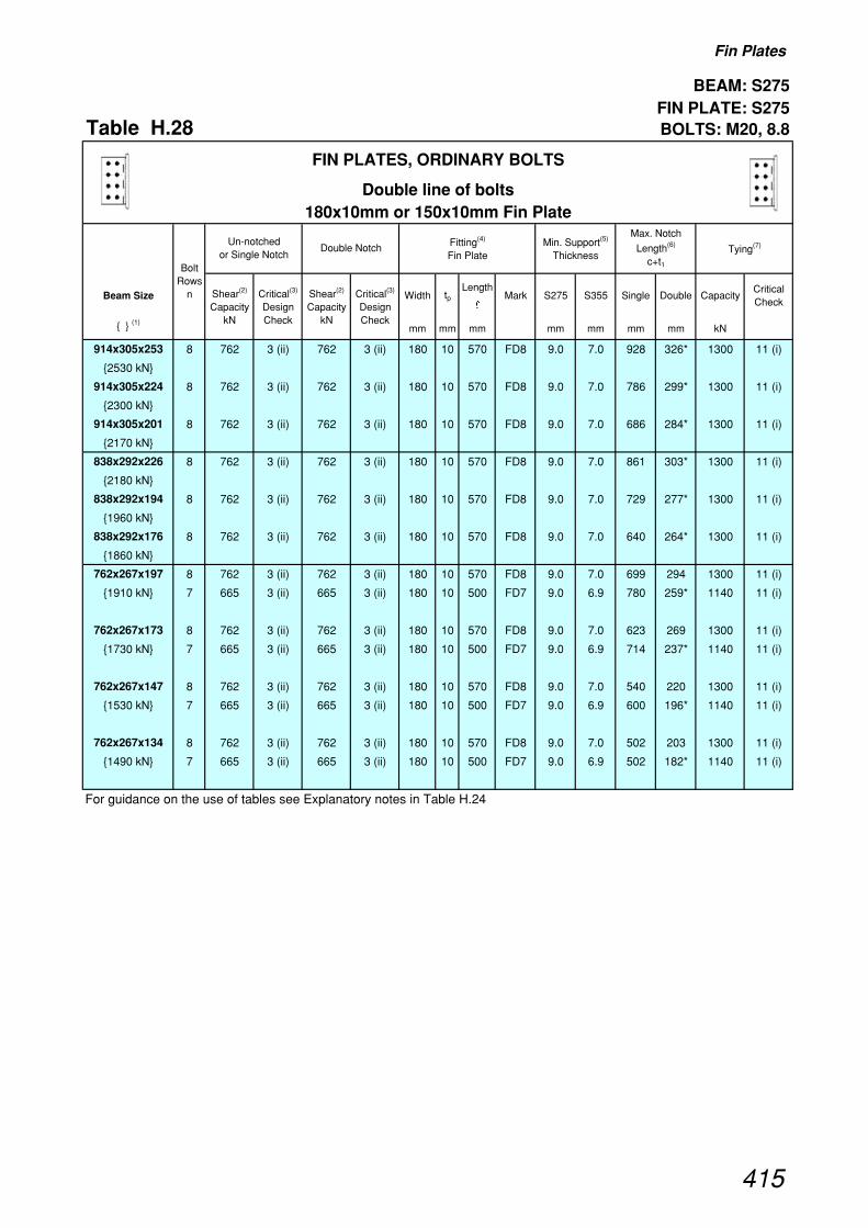
Fin Plates
BEAM: S275 FIN PLATE: S275
Table H.28 BOLTS: M20, 8.8
Beam Size Width tpLength
�Mark S275 S355 Single Double Capacity
Critical Check
{ } (1)mm mm mm mm mm mm mm kN
914x305x253 8 762 3 (ii) 762 3 (ii) 180 10 570 FD8 9.0 7.0 928 326* 1300 11 (i)
{2530 kN}
914x305x224 8 762 3 (ii) 762 3 (ii) 180 10 570 FD8 9.0 7.0 786 299* 1300 11 (i)
{2300 kN}
914x305x201 8 762 3 (ii) 762 3 (ii) 180 10 570 FD8 9.0 7.0 686 284* 1300 11 (i)
{2170 kN}
838x292x226 8 762 3 (ii) 762 3 (ii) 180 10 570 FD8 9.0 7.0 861 303* 1300 11 (i)
{2180 kN}
838x292x194 8 762 3 (ii) 762 3 (ii) 180 10 570 FD8 9.0 7.0 729 277* 1300 11 (i)
{1960 kN}
838x292x176 8 762 3 (ii) 762 3 (ii) 180 10 570 FD8 9.0 7.0 640 264* 1300 11 (i)
{1860 kN}
762x267x197 8 762 3 (ii) 762 3 (ii) 180 10 570 FD8 9.0 7.0 699 294 1300 11 (i)
{1910 kN} 7 665 3 (ii) 665 3 (ii) 180 10 500 FD7 9.0 6.9 780 259* 1140 11 (i)
762x267x173 8 762 3 (ii) 762 3 (ii) 180 10 570 FD8 9.0 7.0 623 269 1300 11 (i)
{1730 kN} 7 665 3 (ii) 665 3 (ii) 180 10 500 FD7 9.0 6.9 714 237* 1140 11 (i)
762x267x147 8 762 3 (ii) 762 3 (ii) 180 10 570 FD8 9.0 7.0 540 220 1300 11 (i)
{1530 kN} 7 665 3 (ii) 665 3 (ii) 180 10 500 FD7 9.0 6.9 600 196* 1140 11 (i)
762x267x134 8 762 3 (ii) 762 3 (ii) 180 10 570 FD8 9.0 7.0 502 203 1300 11 (i)
{1490 kN} 7 665 3 (ii) 665 3 (ii) 180 10 500 FD7 9.0 6.9 502 182* 1140 11 (i)
For guidance on the use of tables see Explanatory notes in Table H.24
Un-notched or Single Notch
Critical(3)
Design Check
Critical(3)
Design Check
Max. Notch
Length(6)
c+t1
Shear(2)
Capacity kN
Shear(2)
Capacity kN
Fitting(4)
Fin Plate
FIN PLATES, ORDINARY BOLTS
Double line of bolts180x10mm or 150x10mm Fin Plate
Double Notch Min. Support(5)
ThicknessTying(7)
Bolt Rows
n
415
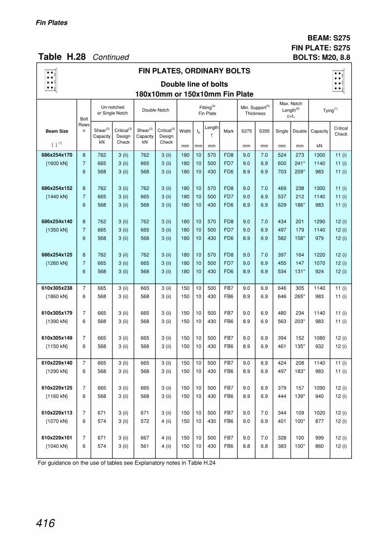
Fin Plates
BEAM: S275 FIN PLATE: S275
Table H.28 Continued BOLTS: M20, 8.8
Beam Size Width tpLength
�Mark S275 S355 Single Double Capacity
Critical Check
{ } (1)mm mm mm mm mm mm mm kN
Un-notched or Single Notch
Critical(3)
Design Check
Critical(3)
Design Check
Max. Notch
Length(6)
c+t1
Shear(2)
Capacity kN
Shear(2)
Capacity kN
Fitting(4)
Fin Plate
FIN PLATES, ORDINARY BOLTS
Double line of bolts180x10mm or 150x10mm Fin Plate
Double Notch Min. Support(5)
ThicknessTying(7)
Bolt Rows
n
686x254x170 8 762 3 (ii) 762 3 (ii) 180 10 570 FD8 9.0 7.0 524 273 1300 11 (i)
{1600 kN} 7 665 3 (ii) 665 3 (ii) 180 10 500 FD7 9.0 6.9 600 241* 1140 11 (i)
6 568 3 (ii) 568 3 (ii) 180 10 430 FD6 8.9 6.9 703 209* 983 11 (i)
686x254x152 8 762 3 (ii) 762 3 (ii) 180 10 570 FD8 9.0 7.0 469 238 1300 11 (i)
{1440 kN} 7 665 3 (ii) 665 3 (ii) 180 10 500 FD7 9.0 6.9 537 212 1140 11 (i)
6 568 3 (ii) 568 3 (ii) 180 10 430 FD6 8.9 6.9 629 186* 983 11 (i)
686x254x140 8 762 3 (ii) 762 3 (ii) 180 10 570 FD8 9.0 7.0 434 201 1290 12 (i)
{1350 kN} 7 665 3 (ii) 665 3 (ii) 180 10 500 FD7 9.0 6.9 497 179 1140 12 (i)
6 568 3 (ii) 568 3 (ii) 180 10 430 FD6 8.9 6.9 582 158* 979 12 (i)
686x254x125 8 762 3 (ii) 762 3 (ii) 180 10 570 FD8 9.0 7.0 397 164 1220 12 (i)
{1260 kN} 7 665 3 (ii) 665 3 (ii) 180 10 500 FD7 9.0 6.9 455 147 1070 12 (i)
6 568 3 (ii) 568 3 (ii) 180 10 430 FD6 8.9 6.9 534 131* 924 12 (i)
610x305x238 7 665 3 (ii) 665 3 (ii) 150 10 500 FB7 9.0 6.9 646 305 1140 11 (i)
{1860 kN} 6 568 3 (ii) 568 3 (ii) 150 10 430 FB6 8.9 6.9 646 265* 983 11 (i)
610x305x179 7 665 3 (ii) 665 3 (ii) 150 10 500 FB7 9.0 6.9 480 234 1140 11 (i)
{1390 kN} 6 568 3 (ii) 568 3 (ii) 150 10 430 FB6 8.9 6.9 563 203* 983 11 (i)
610x305x149 7 665 3 (ii) 665 3 (ii) 150 10 500 FB7 9.0 6.9 394 152 1080 12 (i)
{1150 kN} 6 568 3 (ii) 568 3 (ii) 150 10 430 FB6 8.9 6.9 461 135* 932 12 (i)
610x229x140 7 665 3 (ii) 665 3 (ii) 150 10 500 FB7 9.0 6.9 424 208 1140 11 (i)
{1290 kN} 6 568 3 (ii) 568 3 (ii) 150 10 430 FB6 8.9 6.9 497 183* 983 11 (i)
610x229x125 7 665 3 (ii) 665 3 (ii) 150 10 500 FB7 9.0 6.9 379 157 1090 12 (i)
{1160 kN} 6 568 3 (ii) 568 3 (ii) 150 10 430 FB6 8.9 6.9 444 139* 940 12 (i)
610x229x113 7 671 3 (ii) 671 3 (ii) 150 10 500 FB7 9.0 7.0 344 109 1020 12 (i)
{1070 kN} 6 574 3 (ii) 572 4 (ii) 150 10 430 FB6 9.0 6.9 401 100* 877 12 (i)
610x229x101 7 671 3 (ii) 667 4 (ii) 150 10 500 FB7 9.0 7.0 328 100 999 12 (i)
{1040 kN} 6 574 3 (ii) 561 4 (ii) 150 10 430 FB6 8.8 6.8 383 100* 860 12 (i)
For guidance on the use of tables see Explanatory notes in Table H.24
416

Fin Plates
BEAM: S275 FIN PLATE: S275
Table H.28 Continued BOLTS: M20, 8.8
Beam Size Width tpLength
�Mark S275 S355 Single Double Capacity
Critical Check
{ } (1)mm mm mm mm mm mm mm kN
Un-notched or Single Notch
Critical(3)
Design Check
Critical(3)
Design Check
Max. Notch
Length(6)
c+t1
Shear(2)
Capacity kN
Shear(2)
Capacity kN
Fitting(4)
Fin Plate
FIN PLATES, ORDINARY BOLTS
Double line of bolts180x10mm or 150x10mm Fin Plate
Double Notch Min. Support(5)
ThicknessTying(7)
Bolt Rows
n
533x210x122 6 574 3 (ii) 574 3 (ii) 150 10 430 FB6 9.0 7.0 364 164 983 11 (i)
{1100 kN} 5 476 3 (ii) 476 3 (ii) 150 10 360 FB5 8.9 6.9 438 141* 825 11 (i)
533x210x109 6 574 3 (ii) 574 3 (ii) 150 10 430 FB6 9.0 7.0 326 121 916 12 (i)
{995 kN} 5 476 3 (ii) 476 3 (ii) 150 10 360 FB5 8.9 6.9 392 106* 769 12 (i)
533x210x101 6 574 3 (ii) 556 4 (ii) 150 10 430 FB6 8.7 6.7 300 100 853 12 (i)
{922 kN} 5 476 3 (ii) 450 4 (ii) 150 10 360 FB5 8.4 6.5 362 100* 716 12 (i)
533x210x92 6 574 3 (ii) 540 4 (ii) 150 10 430 FB6 8.5 6.5 286 100 828 12 (i)
{888 kN} 5 476 3 (ii) 437 4 (ii) 150 10 360 FB5 8.2 6.3 345 100* 694 12 (i)
533x210x82 6 574 3 (ii) 513 4 (ii) 150 10 430 FB6 8.0 6.2 258 100 787 12 (i)
{837 kN} 5 476 3 (ii) 415 4 (ii) 150 10 360 FB5 7.8 6.0 317 100* 660 12 (i)
457x191x98 5 476 3 (ii) 475 4 (ii) 150 10 360 FB5 8.9 6.9 283 100 755 12 (i)
{847 kN} 4 378 3 (ii) 361 4 (ii) 150 10 290 FB4 8.4 6.5 357 100* 610 12 (i)
457x191x89 5 476 3 (ii) 437 4 (ii) 150 10 360 FB5 8.2 6.3 257 100 696 12 (i)
{774 kN} 4 378 3 (ii) 333 4 (ii) 150 10 290 FB4 7.7 6.0 324 100* 562 12 (i)
457x191x82 5 476 3 (ii) 428 4 (ii) 150 10 360 FB5 8.0 6.2 246 100 681 12 (i)
{751 kN} 4 378 3 (ii) 325 4 (ii) 150 10 290 FB4 7.6 5.9 311 100* 550 12 (i)
457x191x74 5 476 3 (ii) 389 4 (ii) 150 10 360 FB5 7.3 5.6 205 100 619 12 (i)
{679 kN} 4 378 3 (ii) 296 4 (ii) 150 10 290 FB4 6.9 5.3 279 100* 500 12 (i)
457x191x67 5 476 3 (ii) 367 4 (ii) 150 10 360 FB5 6.9 5.3 165 100 584 12 (i)
{636 kN} 4 362 2 279 4 (ii) 150 10 290 FB4 6.5 5.0 269 100* 472 12 (i)
For guidance on the use of tables see Explanatory notes in Table H.24
417

Fin Plates
BEAM: S275 FIN PLATE: S275
Table H.28 Continued BOLTS: M20, 8.8
Beam Size Width tpLength
�Mark S275 S355 Single Double Capacity
Critical Check
{ } (1)mm mm mm mm mm mm mm kN
Un-notched or Single Notch
Critical(3)
Design Check
Critical(3)
Design Check
Max. Notch
Length(6)
c+t1
Shear(2)
Capacity kN
Shear(2)
Capacity kN
Fitting(4)
Fin Plate
FIN PLATES, ORDINARY BOLTS
Double line of bolts180x10mm or 150x10mm Fin Plate
Double Notch Min. Support(5)
ThicknessTying(7)
Bolt Rows
n
457x152x82 5 476 3 (ii) 437 4 (ii) 150 10 360 FB5 8.2 6.3 253 100 696 12 (i)
{778 kN} 4 378 3 (ii) 333 4 (ii) 150 10 290 FB4 7.7 6.0 319 100* 562 12 (i)
457x152x74 5 476 3 (ii) 400 4 (ii) 150 10 360 FB5 7.5 5.8 223 100 636 12 (i)
{705 kN} 4 378 3 (ii) 304 4 (ii) 150 10 290 FB4 7.1 5.5 287 100* 514 12 (i)
457x152x67 5 476 3 (ii) 389 4 (ii) 150 10 360 FB5 7.3 5.6 200 100 619 12 (i)
{680 kN} 4 378 3 (ii) 296 4 (ii) 150 10 290 FB4 6.9 5.3 272 100* 500 12 (i)
457x152x60 5 456 4 (ii) 350 4 (ii) 150 10 360 FB5 6.5 5.1 161 100 557 12 (i)
{608 kN} 4 345 2 266 4 (ii) 150 10 290 FB4 6.2 4.8 265 100* 450 12 (i)
457x152x52 5 426 4 (ii) 329 4 (ii) 150 10 360 FB5 6.1 4.8 153 100 523 12 (i)
{564 kN} 4 323 2 250 4 (ii) 150 10 290 FB4 5.8 4.5 255 100* 422 12 (i)
406x178x74 4 378 3 (ii) 312 4 (ii) 150 10 290 FB4 7.3 5.6 236 100 528 12 (i)
{647 kN}
406x178x67 4 374 2 289 4 (ii) 150 10 290 FB4 6.7 5.2 216 100 489 12 (i)
{594 kN}
406x178x60 4 336 2 260 4 (ii) 150 10 290 FB4 6.0 4.7 214 100 439 12 (i)
{530 kN}
406x178x54 4 328 2 253 4 (ii) 150 10 290 FB4 5.9 4.6 206 100 428 12 (i)
{512 kN}
406x140x46 4 289 2 224 4 (ii) 150 10 290 FB4 5.2 4.0 204 100 378 12 (i)
{452 kN}
406x140x39 4 272 2 210 4 (ii) 150 10 290 FB4 4.9 3.8 194 100 356 12 (i)
{420 kN}
356x171x67 3 251 2 202 4 (ii) 150 10 220 FB3 6.2 4.8 258 100* 385 12 (i)
{546 kN}
356x171x57 3 223 2 180 4 (ii) 150 10 220 FB3 5.5 4.3 249 100* 343 12 (i)
{478 kN}
356x171x51 3 204 2 164 4 (ii) 150 10 220 FB3 5.0 3.9 244 100* 313 12 (i)
{433 kN}
356x171x45 3 193 2 155 4 (ii) 150 10 220 FB3 4.8 3.7 236 100* 296 12 (i)
{406 kN}
356x127x39 3 182 2 146 4 (ii) 150 10 220 FB3 4.5 3.5 232 100* 280 12 (i)
{385 kN}
356x127x33 3 165 2 133 4 (ii) 150 10 220 FB3 4.1 3.2 223 100* 254 12 (i)
{346 kN}
For guidance on the use of tables see Explanatory notes in Table H.24
418

Fin Plates
BEAM: S275 FIN PLATE: S275
Table H.28 Continued BOLTS: M20, 8.8
Beam Size Width tpLength
�Mark S275 S355 Single Double Capacity
Critical Check
{ } (1)mm mm mm mm mm mm mm kN
Un-notched or Single Notch
Critical(3)
Design Check
Critical(3)
Design Check
Max. Notch
Length(6)
c+t1
Shear(2)
Capacity kN
Shear(2)
Capacity kN
Fitting(4)
Fin Plate
FIN PLATES, ORDINARY BOLTS
Double line of bolts180x10mm or 150x10mm Fin Plate
Double Notch Min. Support(5)
ThicknessTying(7)
Bolt Rows
n
305x165x54 3 218 2 175 4 (ii) 150 10 220 FB3 5.4 4.2 181 100 335 12 (i)
{405 kN}
305x165x46 3 185 2 149 4 (ii) 150 10 220 FB3 4.5 3.5 178 100 284 12 (i)
{339 kN}
305x165x40 3 165 2 133 4 (ii) 150 10 220 FB3 4.1 3.2 173 100 254 12 (i)
{300 kN}
305x127x48 3 248 2 200 4 (ii) 150 10 220 FB3 6.1 4.7 172 100 381 12 (i)
{462 kN}
305x127x42 3 220 2 177 4 (ii) 150 10 220 FB3 5.4 4.2 167 100 339 12 (i)
{406 kN}
305x127x37 3 196 2 158 4 (ii) 150 10 220 FB3 4.8 3.7 164 100 301 12 (i)
{357 kN}
305x102x33 3 182 2 146 4 (ii) 150 10 220 FB3 4.5 3.5 172 100 280 12 (i)
{341 kN}
305x102x28 3 165 2 133 4 (ii) 150 10 220 FB3 4.1 3.2 165 100 254 12 (i)
{306 kN}
305x102x25 3 160 2 129 4 (ii) 150 10 220 FB3 3.9 3.1 157 100 246 12 (i)
{292 kN}
254x146x43 2 108 2 74 4 (ii) 150 10 150 FB2 3.3 2.6 218 100* 210 12 (i)
{308 kN}
254x146x37 2 94 2 65 4 (ii) 150 10 150 FB2 2.9 2.3 212 100* 184 12 (i)
{266 kN}
254x146x31 2 90 2 62 4 (ii) 150 10 150 FB2 2.8 2.2 200 100* 175 12 (i)
{249 kN}
254x102x28 2 94 2 65 4 (ii) 150 10 150 FB2 2.9 2.3 208 100* 184 12 (i)
{271 kN}
254x102x25 2 90 2 62 4 (ii) 150 10 150 FB2 2.8 2.2 200 100* 175 12 (i)
{255 kN}
254x102x22 2 85 2 59 4 (ii) 150 10 150 FB2 2.6 2.0 190 100* 166 12 (i)
{239 kN}
For guidance on the use of tables see Explanatory notes in Table H.24
419

Fin Plates
BEAM: S355 FIN PLATE: S275
Table H.29 BOLTS: M20, 8.8
Beam Size Width tpLength
�Mark S275 S355 Single Double Capacity
Critical Check
{ } (1)mm mm mm mm mm mm mm kN
914x305x253 8 639 2 639 2 120 10 570 FC8 7.5 5.8 685 506* 1100 11 (ii)
{3290 kN}
914x305x224 8 639 2 639 2 120 10 570 FC8 7.5 5.8 543 465* 1100 11 (ii)
{3000 kN}
914x305x201 8 639 2 639 2 120 10 570 FC8 7.5 5.8 474 441* 1100 11 (ii)
{2820 kN}
838x292x226 8 639 2 639 2 120 10 570 FC8 7.5 5.8 644 471* 1100 11 (ii)
{2840 kN}
838x292x194 8 639 2 639 2 120 10 570 FC8 7.5 5.8 504 430* 1100 11 (ii)
{2560 kN}
838x292x176 8 639 2 639 2 120 10 570 FC8 7.5 5.8 443 409* 1100 11 (ii)
{2420 kN}
762x267x197 8 639 2 639 2 120 10 570 FC8 7.5 5.8 715 456 1100 11 (ii)
{2490 kN} 7 542 2 542 2 120 10 500 FC7 7.3 5.7 715 414* 966 11 (ii)
762x267x173 8 639 2 639 2 120 10 570 FC8 7.5 5.8 564 418 1100 11 (ii)
{2260 kN} 7 542 2 542 2 120 10 500 FC7 7.3 5.7 564 379* 966 11 (ii)
762x267x147 8 639 2 639 2 120 10 570 FC8 7.5 5.8 416 374 1100 11 (ii)
{2000 kN} 7 542 2 542 2 120 10 500 FC7 7.3 5.7 416 340* 966 11 (ii)
762x267x134 8 639 2 639 2 120 10 570 FC8 7.5 5.8 348 348 1060 12 (ii)
{1920 kN} 7 542 2 542 2 120 10 500 FC7 7.3 5.7 348 328* 924 12 (ii)
For guidance on the use of tables see Explanatory notes in Table H.24
Un-notched or Single Notch
Critical(3)
Design Check
Critical(3)
Design Check
Max. Notch
Length(6)
c+t1
Shear(2)
Capacity kN
Shear(2)
Capacity kN
Fitting(4)
Fin Plate
FIN PLATES, ORDINARY BOLTS
Single line of bolts120x10mm or 100x10mm Fin Plate
Double Notch Min. Support(5)
ThicknessTying(7)
Bolt Rows
n
420
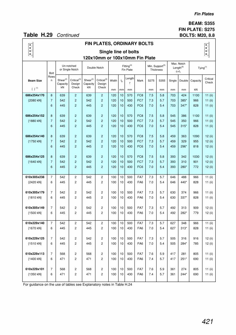
Fin Plates
BEAM: S355 FIN PLATE: S275
Table H.29 Continued BOLTS: M20, 8.8
Beam Size Width tpLength
�Mark S275 S355 Single Double Capacity
Critical Check
{ } (1)mm mm mm mm mm mm mm kN
Un-notched or Single Notch
Critical(3)
Design Check
Critical(3)
Design Check
Max. Notch
Length(6)
c+t1
Shear(2)
Capacity kN
Shear(2)
Capacity kN
Fitting(4)
Fin Plate
FIN PLATES, ORDINARY BOLTS
Single line of bolts120x10mm or 100x10mm Fin Plate
Double Notch Min. Support(5)
ThicknessTying(7)
Bolt Rows
n
686x254x170 8 639 2 639 2 120 10 570 FC8 7.5 5.8 703 424 1100 11 (ii)
{2080 kN} 7 542 2 542 2 120 10 500 FC7 7.3 5.7 703 385* 966 11 (ii)
6 445 2 445 2 120 10 430 FC6 7.0 5.4 703 347* 828 11 (ii)
686x254x152 8 639 2 639 2 120 10 570 FC8 7.5 5.8 545 386 1100 11 (ii)
{1880 kN} 7 542 2 542 2 120 10 500 FC7 7.3 5.7 545 350 966 11 (ii)
6 445 2 445 2 120 10 430 FC6 7.0 5.4 545 315* 828 11 (ii)
686x254x140 8 639 2 639 2 120 10 570 FC8 7.5 5.8 459 363 1090 12 (ii)
{1750 kN} 7 542 2 542 2 120 10 500 FC7 7.3 5.7 459 329 955 12 (ii)
6 445 2 445 2 120 10 430 FC6 7.0 5.4 459 296* 818 12 (ii)
686x254x125 8 639 2 639 2 120 10 570 FC8 7.5 5.8 393 342 1030 12 (ii)
{1640 kN} 7 542 2 542 2 120 10 500 FC7 7.3 5.7 393 310 901 12 (ii)
6 445 2 445 2 120 10 430 FC6 7.0 5.4 393 280* 772 12 (ii)
610x305x238 7 542 2 542 2 100 10 500 FA7 7.3 5.7 646 488 966 11 (ii)
{2420 kN} 6 445 2 445 2 100 10 430 FA6 7.0 5.4 646 440* 828 11 (ii)
610x305x179 7 542 2 542 2 100 10 500 FA7 7.3 5.7 630 374 966 11 (ii)
{1810 kN} 6 445 2 445 2 100 10 430 FA6 7.0 5.4 630 337* 828 11 (ii)
610x305x149 7 542 2 542 2 100 10 500 FA7 7.3 5.7 492 313 909 12 (ii)
{1500 kN} 6 445 2 445 2 100 10 430 FA6 7.0 5.4 492 282* 779 12 (ii)
610x229x140 7 542 2 542 2 100 10 500 FA7 7.3 5.7 627 348 966 11 (ii)
{1670 kN} 6 445 2 445 2 100 10 430 FA6 7.0 5.4 627 313* 828 11 (ii)
610x229x125 7 542 2 542 2 100 10 500 FA7 7.3 5.7 505 316 916 12 (ii)
{1510 kN} 6 445 2 445 2 100 10 430 FA6 7.0 5.4 505 284* 785 12 (ii)
610x229x113 7 568 2 568 2 100 10 500 FA7 7.6 5.9 417 281 805 11 (ii)
{1400 kN} 6 471 2 471 2 100 10 430 FA6 7.4 5.7 417 251* 690 11 (ii)
610x229x101 7 568 2 568 2 100 10 500 FA7 7.6 5.9 361 274 805 11 (ii)
{1350 kN} 6 471 2 471 2 100 10 430 FA6 7.4 5.7 361 244* 690 11 (ii)
For guidance on the use of tables see Explanatory notes in Table H.24
421

Fin Plates
BEAM: S355 FIN PLATE: S275
Table H.29 Continued BOLTS: M20, 8.8
Beam Size Width tpLength
�Mark S275 S355 Single Double Capacity
Critical Check
{ } (1)mm mm mm mm mm mm mm kN
Un-notched or Single Notch
Critical(3)
Design Check
Critical(3)
Design Check
Max. Notch
Length(6)
c+t1
Shear(2)
Capacity kN
Shear(2)
Capacity kN
Fitting(4)
Fin Plate
FIN PLATES, ORDINARY BOLTS
Single line of bolts120x10mm or 100x10mm Fin Plate
Double Notch Min. Support(5)
ThicknessTying(7)
Bolt Rows
n
533x210x122 6 471 2 471 2 100 10 430 FA6 7.4 5.7 555 287 690 11 (ii)
{1430 kN} 5 374 2 374 2 100 10 360 FA5 7.0 5.4 555 253* 575 11 (ii)
533x210x109 6 471 2 471 2 100 10 430 FA6 7.4 5.7 517 262 690 11 (ii)
{1300 kN} 5 374 2 374 2 100 10 360 FA5 7.0 5.4 550 231* 575 11 (ii)
533x210x101 6 471 2 471 2 100 10 430 FA6 7.4 5.7 476 244 690 11 (ii)
{1200 kN} 5 374 2 374 2 100 10 360 FA5 7.0 5.4 491 215* 575 11 (ii)
533x210x92 6 471 2 471 2 100 10 430 FA6 7.4 5.7 409 235 667 12 (ii)
{1150 kN} 5 374 2 374 2 100 10 360 FA5 7.0 5.4 409 207* 556 12 (ii)
533x210x82 6 452 2 452 2 100 10 430 FA6 7.1 5.5 359 232 634 12 (ii)
{1080 kN} 5 359 2 359 2 100 10 360 FA5 6.7 5.2 359 205* 528 12 (ii)
457x191x98 5 374 2 374 2 100 10 360 FA5 7.0 5.4 469 227 575 11 (ii)
{1100 kN} 4 279 2 279 2 100 10 290 FA4 6.5 5.0 477 197* 460 11 (ii)
457x191x89 5 374 2 374 2 100 10 360 FA5 7.0 5.4 425 209 575 11 (ii)
{1010 kN} 4 279 2 279 2 100 10 290 FA4 6.5 5.0 473 182* 460 11 (ii)
457x191x82 5 371 2 371 2 100 10 360 FA5 6.9 5.4 409 205 545 12 (ii)
{970 kN} 4 277 2 277 2 100 10 290 FA4 6.4 5.0 470 178* 436 12 (ii)
457x191x74 5 337 2 337 2 100 10 360 FA5 6.3 4.9 394 205 495 12 (ii)
{876 kN} 4 251 2 251 2 100 10 290 FA4 5.8 4.5 394 178* 396 12 (ii)
457x191x67 5 318 2 318 2 100 10 360 FA5 6.0 4.6 339 205 468 12 (ii)
{821 kN} 4 237 2 237 2 100 10 290 FA4 5.5 4.3 339 178* 374 12 (ii)
For guidance on the use of tables see Explanatory notes in Table H.24
422

Fin Plates
BEAM: S355 FIN PLATE: S275
Table H.29 Continued BOLTS: M20, 8.8
Beam Size Width tpLength
�Mark S275 S355 Single Double Capacity
Critical Check
{ } (1)mm mm mm mm mm mm mm kN
Un-notched or Single Notch
Critical(3)
Design Check
Critical(3)
Design Check
Max. Notch
Length(6)
c+t1
Shear(2)
Capacity kN
Shear(2)
Capacity kN
Fitting(4)
Fin Plate
FIN PLATES, ORDINARY BOLTS
Single line of bolts120x10mm or 100x10mm Fin Plate
Double Notch Min. Support(5)
ThicknessTying(7)
Bolt Rows
n
457x152x82 5 374 2 374 2 100 10 360 FA5 7.0 5.4 419 209 575 11 (ii)
{1010 kN} 4 279 2 279 2 100 10 290 FA4 6.5 5.0 476 182* 460 11 (ii)
457x152x74 5 359 2 359 2 100 10 360 FA5 6.7 5.2 392 199 528 12 (ii)
{918 kN} 4 268 2 268 2 100 10 290 FA4 6.2 4.8 466 173* 422 12 (ii)
457x152x67 5 337 2 337 2 100 10 360 FA5 6.3 4.9 392 205 495 12 (ii)
{878 kN} 4 251 2 251 2 100 10 290 FA4 5.8 4.5 392 178* 396 12 (ii)
457x152x60 5 303 2 303 2 100 10 360 FA5 5.7 4.4 293 205 446 12 (ii)
{784 kN} 4 226 2 226 2 100 10 290 FA4 5.3 4.1 293 178* 356 12 (ii)
457x152x52 5 284 2 284 2 100 10 360 FA5 5.3 4.1 249 205 418 12 (ii)
{728 kN} 4 212 2 212 2 100 10 290 FA4 4.9 3.8 249 178* 334 12 (ii)
406x178x74 4 265 2 265 2 100 10 290 FA4 6.2 4.8 423 178 418 12 (ii)
{835 kN}
406x178x67 4 246 2 246 2 100 10 290 FA4 5.7 4.4 419 178 387 12 (ii)
{767 kN}
406x178x60 4 221 2 221 2 100 10 290 FA4 5.1 4.0 338 178 348 12 (ii)
{684 kN}
406x178x54 4 215 2 215 2 100 10 290 FA4 5.0 3.9 320 178 339 12 (ii)
{660 kN}
406x140x46 4 190 2 190 2 100 10 290 FA4 4.4 3.4 223 178 299 12 (ii)
{584 kN}
406x140x39 4 179 2 179 2 100 10 290 FA4 4.2 3.2 192 178 282 12 (ii)
{543 kN}
356x171x67 3 171 2 171 2 100 10 220 FA3 5.2 4.1 373 152* 300 12 (ii)
{704 kN}
356x171x57 3 153 2 153 2 100 10 220 FA3 4.7 3.6 368 152* 267 12 (ii)
{618 kN}
356x171x51 3 139 2 139 2 100 10 220 FA3 4.3 3.3 365 152* 244 12 (ii)
{560 kN}
356x171x45 3 132 2 132 2 100 10 220 FA3 4.0 3.1 316 152* 231 12 (ii)
{524 kN}
356x127x39 3 124 2 124 2 100 10 220 FA3 3.8 2.9 263 152* 218 12 (ii)
{497 kN}
356x127x33 3 113 2 113 2 100 10 220 FA3 3.5 2.7 205 152* 198 12 (ii)
{446 kN}
For guidance on the use of tables see Explanatory notes in Table H.24
423

Fin Plates
BEAM: S355 FIN PLATE: S275
Table H.29 Continued BOLTS: M20, 8.8
Beam Size Width tpLength
�Mark S275 S355 Single Double Capacity
Critical Check
{ } (1)mm mm mm mm mm mm mm kN
Un-notched or Single Notch
Critical(3)
Design Check
Critical(3)
Design Check
Max. Notch
Length(6)
c+t1
Shear(2)
Capacity kN
Shear(2)
Capacity kN
Fitting(4)
Fin Plate
FIN PLATES, ORDINARY BOLTS
Single line of bolts120x10mm or 100x10mm Fin Plate
Double Notch Min. Support(5)
ThicknessTying(7)
Bolt Rows
n
305x165x54 3 149 2 149 2 100 10 220 FA3 4.6 3.5 320 152 261 12 (ii)
{522 kN}
305x165x46 3 126 2 126 2 100 10 220 FA3 3.9 3.0 317 152 221 12 (ii)
{438 kN}
305x165x40 3 113 2 113 2 100 10 220 FA3 3.5 2.7 268 152 198 12 (ii)
{388 kN}
305x127x48 3 169 2 169 2 100 10 220 FA3 5.2 4.0 321 152 297 12 (ii)
{596 kN}
305x127x42 3 151 2 151 2 100 10 220 FA3 4.6 3.6 316 152 264 12 (ii)
{523 kN}
305x127x37 3 134 2 134 2 100 10 220 FA3 4.1 3.2 311 152 234 12 (ii)
{460 kN}
305x102x33 3 124 2 124 2 100 10 220 FA3 3.8 2.9 323 152 218 12 (ii)
{440 kN}
305x102x28 3 113 2 113 2 100 10 220 FA3 3.5 2.7 259 152 198 12 (ii)
{395 kN}
305x102x25 3 109 2 109 2 100 10 220 FA3 3.3 2.6 241 152 191 12 (ii)
{377 kN}
254x146x43 2 76 2 76 2 100 10 150 FA2 3.4 2.6 270 126* 158 12 (ii)
{398 kN}
254x146x37 2 66 2 66 2 100 10 150 FA2 3.0 2.3 266 126* 139 12 (ii)
{344 kN}
254x146x31 2 63 2 63 2 100 10 150 FA2 2.8 2.2 261 126* 132 12 (ii)
{321 kN}
254x102x28 2 66 2 66 2 100 10 150 FA2 3.0 2.3 270 126* 139 12 (ii)
{349 kN}
254x102x25 2 63 2 63 2 100 10 150 FA2 2.8 2.2 267 126* 132 12 (ii)
{329 kN}
254x102x22 2 60 2 60 2 100 10 150 FA2 2.7 2.1 264 126* 125 12 (ii)
{308 kN}
For guidance on the use of tables see Explanatory notes in Table H.24
424

Fin Plates
BEAM: S355 FIN PLATE: S275
Table H.30 BOLTS: M20, 8.8
Beam Size Width tpLength
�Mark S275 S355 Single Double Capacity
Critical Check
{ } (1)mm mm mm mm mm mm mm kN
914x305x253 8 762 3 (ii) 762 3 (ii) 180 10 570 FD8 9.0 7.0 685 424* 1300 11 (i)
{3290 kN}
914x305x224 8 762 3 (ii) 762 3 (ii) 180 10 570 FD8 9.0 7.0 543 390* 1300 11 (i)
{3000 kN}
914x305x201 8 762 3 (ii) 762 3 (ii) 180 10 570 FD8 9.0 7.0 474 370* 1300 11 (i)
{2820 kN}
838x292x226 8 762 3 (ii) 762 3 (ii) 180 10 570 FD8 9.0 7.0 644 395* 1300 11 (i)
{2840 kN}
838x292x194 8 762 3 (ii) 762 3 (ii) 180 10 570 FD8 9.0 7.0 504 360* 1300 11 (i)
{2560 kN}
838x292x176 8 762 3 (ii) 762 3 (ii) 180 10 570 FD8 9.0 7.0 443 343* 1300 11 (i)
{2420 kN}
762x267x197 8 762 3 (ii) 762 3 (ii) 180 10 570 FD8 9.0 7.0 715 382 1300 11 (i)
{2490 kN} 7 665 3 (ii) 665 3 (ii) 180 10 500 FD7 9.0 6.9 715 337* 1140 11 (i)
762x267x173 8 762 3 (ii) 762 3 (ii) 180 10 570 FD8 9.0 7.0 564 351 1300 11 (i)
{2260 kN} 7 665 3 (ii) 665 3 (ii) 180 10 500 FD7 9.0 6.9 564 309* 1140 11 (i)
762x267x147 8 762 3 (ii) 762 3 (ii) 180 10 570 FD8 9.0 7.0 416 314 1300 11 (i)
{2000 kN} 7 665 3 (ii) 665 3 (ii) 180 10 500 FD7 9.0 6.9 416 277* 1140 11 (i)
762x267x134 8 762 3 (ii) 762 3 (ii) 180 10 570 FD8 9.0 7.0 348 303 1300 11 (i)
{1920 kN} 7 665 3 (ii) 665 3 (ii) 180 10 500 FD7 9.0 6.9 348 267* 1140 11 (i)
For guidance on the use of tables see Explanatory notes in Table H.24
Un-notched or Single Notch
Critical(3)
Design Check
Critical(3)
Design Check
Max. Notch
Length(6)
c+t1
Shear(2)
Capacity kN
Shear(2)
Capacity kN
Fitting(4)
Fin Plate
FIN PLATES, ORDINARY BOLTS
Double line of bolts180x10mm or 150x10mm Fin Plate
Double Notch Min. Support(5)
ThicknessTying(7)
Bolt Rows
n
425

Fin Plates
BEAM: S355 FIN PLATE: S275
Table H.30 Continued BOLTS: M20, 8.8
Beam Size Width tpLength
�Mark S275 S355 Single Double Capacity
Critical Check
{ } (1)mm mm mm mm mm mm mm kN
Un-notched or Single Notch
Critical(3)
Design Check
Critical(3)
Design Check
Max. Notch
Length(6)
c+t1
Shear(2)
Capacity kN
Shear(2)
Capacity kN
Fitting(4)
Fin Plate
FIN PLATES, ORDINARY BOLTS
Double line of bolts180x10mm or 150x10mm Fin Plate
Double Notch Min. Support(5)
ThicknessTying(7)
Bolt Rows
n
686x254x170 8 762 3 (ii) 762 3 (ii) 180 10 570 FD8 9.0 7.0 682 355 1300 11 (i)
{2080 kN} 7 665 3 (ii) 665 3 (ii) 180 10 500 FD7 9.0 6.9 703 313* 1140 11 (i)
6 568 3 (ii) 568 3 (ii) 180 10 430 FD6 8.9 6.9 703 272* 983 11 (i)
686x254x152 8 762 3 (ii) 762 3 (ii) 180 10 570 FD8 9.0 7.0 545 324 1300 11 (i)
{1880 kN} 7 665 3 (ii) 665 3 (ii) 180 10 500 FD7 9.0 6.9 545 285 1140 11 (i)
6 568 3 (ii) 568 3 (ii) 180 10 430 FD6 8.9 6.9 545 247* 983 11 (i)
686x254x140 8 762 3 (ii) 762 3 (ii) 180 10 570 FD8 9.0 7.0 459 304 1300 11 (i)
{1750 kN} 7 665 3 (ii) 665 3 (ii) 180 10 500 FD7 9.0 6.9 459 268 1140 11 (i)
6 568 3 (ii) 568 3 (ii) 180 10 430 FD6 8.9 6.9 459 232* 983 11 (i)
686x254x125 8 762 3 (ii) 762 3 (ii) 180 10 570 FD8 9.0 7.0 393 287 1300 11 (i)
{1640 kN} 7 665 3 (ii) 665 3 (ii) 180 10 500 FD7 9.0 6.9 393 253 1140 11 (i)
6 568 3 (ii) 568 3 (ii) 180 10 430 FD6 8.9 6.9 393 219* 983 11 (i)
610x305x238 7 665 3 (ii) 665 3 (ii) 150 10 500 FB7 9.0 6.9 646 398 1140 11 (i)
{2420 kN} 6 568 3 (ii) 568 3 (ii) 150 10 430 FB6 8.9 6.9 646 345* 983 11 (i)
610x305x179 7 665 3 (ii) 665 3 (ii) 150 10 500 FB7 9.0 6.9 625 305 1140 11 (i)
{1810 kN} 6 568 3 (ii) 568 3 (ii) 150 10 430 FB6 8.9 6.9 630 264* 983 11 (i)
610x305x149 7 665 3 (ii) 665 3 (ii) 150 10 500 FB7 9.0 6.9 492 255 1140 11 (i)
{1500 kN} 6 568 3 (ii) 568 3 (ii) 150 10 430 FB6 8.9 6.9 492 221* 983 11 (i)
610x229x140 7 665 3 (ii) 665 3 (ii) 150 10 500 FB7 9.0 6.9 553 283 1140 11 (i)
{1670 kN} 6 568 3 (ii) 568 3 (ii) 150 10 430 FB6 8.9 6.9 627 245* 983 11 (i)
610x229x125 7 665 3 (ii) 665 3 (ii) 150 10 500 FB7 9.0 6.9 494 257 1140 11 (i)
{1510 kN} 6 568 3 (ii) 568 3 (ii) 150 10 430 FB6 8.9 6.9 505 223* 983 11 (i)
610x229x113 7 671 3 (ii) 671 3 (ii) 150 10 500 FB7 9.0 7.0 417 228 1140 11 (i)
{1400 kN} 6 574 3 (ii) 574 3 (ii) 150 10 430 FB6 9.0 7.0 417 199* 983 11 (i)
610x229x101 7 671 3 (ii) 671 3 (ii) 150 10 500 FB7 9.0 7.0 361 213 1140 11 (i)
{1350 kN} 6 574 3 (ii) 574 3 (ii) 150 10 430 FB6 9.0 7.0 361 186* 983 11 (i)
For guidance on the use of tables see Explanatory notes in Table H.24
426

Fin Plates
BEAM: S355 FIN PLATE: S275
Table H.30 Continued BOLTS: M20, 8.8
Beam Size Width tpLength
�Mark S275 S355 Single Double Capacity
Critical Check
{ } (1)mm mm mm mm mm mm mm kN
Un-notched or Single Notch
Critical(3)
Design Check
Critical(3)
Design Check
Max. Notch
Length(6)
c+t1
Shear(2)
Capacity kN
Shear(2)
Capacity kN
Fitting(4)
Fin Plate
FIN PLATES, ORDINARY BOLTS
Double line of bolts180x10mm or 150x10mm Fin Plate
Double Notch Min. Support(5)
ThicknessTying(7)
Bolt Rows
n
533x210x122 6 574 3 (ii) 574 3 (ii) 150 10 430 FB6 9.0 7.0 474 235 983 11 (i)
{1430 kN} 5 476 3 (ii) 476 3 (ii) 150 10 360 FB5 8.9 6.9 555 199* 825 11 (i)
533x210x109 6 574 3 (ii) 574 3 (ii) 150 10 430 FB6 9.0 7.0 424 215 983 11 (i)
{1300 kN} 5 476 3 (ii) 476 3 (ii) 150 10 360 FB5 8.9 6.9 511 181* 825 11 (i)
533x210x101 6 574 3 (ii) 574 3 (ii) 150 10 430 FB6 9.0 7.0 391 186 983 11 (i)
{1200 kN} 5 476 3 (ii) 476 3 (ii) 150 10 360 FB5 8.9 6.9 471 160* 825 11 (i)
533x210x92 6 574 3 (ii) 574 3 (ii) 150 10 430 FB6 9.0 7.0 370 167 983 11 (i)
{1150 kN} 5 476 3 (ii) 476 3 (ii) 150 10 360 FB5 8.9 6.9 409 144* 825 11 (i)
533x210x82 6 574 3 (ii) 574 3 (ii) 150 10 430 FB6 9.0 7.0 340 141 983 11 (i)
{1080 kN} 5 476 3 (ii) 476 3 (ii) 150 10 360 FB5 8.9 6.9 359 123* 825 11 (i)
457x191x98 5 476 3 (ii) 476 3 (ii) 150 10 360 FB5 8.9 6.9 369 178 825 11 (i)
{1100 kN} 4 378 3 (ii) 378 3 (ii) 150 10 290 FB4 8.8 6.8 465 146* 667 11 (i)
457x191x89 5 476 3 (ii) 476 3 (ii) 150 10 360 FB5 8.9 6.9 334 148 825 11 (i)
{1010 kN} 4 378 3 (ii) 378 3 (ii) 150 10 290 FB4 8.8 6.8 421 125* 667 11 (i)
457x191x82 5 476 3 (ii) 476 3 (ii) 150 10 360 FB5 8.9 6.9 318 136 825 11 (i)
{970 kN} 4 378 3 (ii) 378 3 (ii) 150 10 290 FB4 8.8 6.8 401 116* 667 11 (i)
457x191x74 5 476 3 (ii) 469 4 (ii) 150 10 360 FB5 8.8 6.8 286 100 799 12 (i)
{876 kN} 4 378 3 (ii) 360 4 (ii) 150 10 290 FB4 8.3 6.5 361 100* 645 12 (i)
457x191x67 5 476 3 (ii) 443 4 (ii) 150 10 360 FB5 8.3 6.4 264 100 754 12 (i)
{821 kN} 4 362 2 340 4 (ii) 150 10 290 FB4 7.9 6.1 339 100* 610 12 (i)
For guidance on the use of tables see Explanatory notes in Table H.24
427

Fin Plates
BEAM: S355 FIN PLATE: S275
Table H.30 Continued BOLTS: M20, 8.8
Beam Size Width tpLength
�Mark S275 S355 Single Double Capacity
Critical Check
{ } (1)mm mm mm mm mm mm mm kN
Un-notched or Single Notch
Critical(3)
Design Check
Critical(3)
Design Check
Max. Notch
Length(6)
c+t1
Shear(2)
Capacity kN
Shear(2)
Capacity kN
Fitting(4)
Fin Plate
FIN PLATES, ORDINARY BOLTS
Double line of bolts180x10mm or 150x10mm Fin Plate
Double Notch Min. Support(5)
ThicknessTying(7)
Bolt Rows
n
457x152x82 5 476 3 (ii) 476 3 (ii) 150 10 360 FB5 8.9 6.9 329 148 825 11 (i)
{1010 kN} 4 378 3 (ii) 378 3 (ii) 150 10 290 FB4 8.8 6.8 415 125* 667 11 (i)
457x152x74 5 476 3 (ii) 476 3 (ii) 150 10 360 FB5 8.9 6.9 296 110 825 11 (i)
{918 kN} 4 378 3 (ii) 373 4 (ii) 150 10 290 FB4 8.7 6.7 373 100* 667 11 (i)
457x152x67 5 476 3 (ii) 469 4 (ii) 150 10 360 FB5 8.8 6.8 279 100 799 12 (i)
{878 kN} 4 378 3 (ii) 360 4 (ii) 150 10 290 FB4 8.3 6.5 352 100* 645 12 (i)
457x152x60 5 476 3 (ii) 422 4 (ii) 150 10 360 FB5 7.9 6.1 247 100 719 12 (i)
{784 kN} 4 345 2 324 4 (ii) 150 10 290 FB4 7.5 5.8 293 100* 581 12 (i)
457x152x52 5 451 2 396 4 (ii) 150 10 360 FB5 7.4 5.7 236 100 675 12 (i)
{728 kN} 4 323 2 304 4 (ii) 150 10 290 FB4 7.0 5.5 249 100* 545 12 (i)
406x178x74 4 378 3 (ii) 378 3 (ii) 150 10 290 FB4 8.8 6.8 305 102 667 11 (i)
{835 kN}
406x178x67 4 374 2 352 4 (ii) 150 10 290 FB4 8.2 6.3 279 100 631 12 (i)
{767 kN}
406x178x60 4 336 2 316 4 (ii) 150 10 290 FB4 7.3 5.7 276 100 567 12 (i)
{684 kN}
406x178x54 4 328 2 308 4 (ii) 150 10 290 FB4 7.1 5.5 266 100 552 12 (i)
{660 kN}
406x140x46 4 289 2 272 4 (ii) 150 10 290 FB4 6.3 4.9 223 100 488 12 (i)
{584 kN}
406x140x39 4 272 2 256 4 (ii) 150 10 290 FB4 5.9 4.6 192 100 459 12 (i)
{543 kN}
356x171x67 3 251 2 251 2 150 10 220 FB3 7.7 5.9 333 101* 497 12 (i)
{704 kN}
356x171x57 3 223 2 223 2 150 10 220 FB3 6.8 5.3 321 101* 443 12 (i)
{618 kN}
356x171x51 3 204 2 204 2 150 10 220 FB3 6.2 4.8 315 101* 405 12 (i)
{560 kN}
356x171x45 3 193 2 193 2 150 10 220 FB3 5.9 4.6 304 101* 383 12 (i)
{524 kN}
356x127x39 3 182 2 182 2 150 10 220 FB3 5.6 4.3 263 101* 361 12 (i)
{497 kN}
356x127x33 3 165 2 165 2 150 10 220 FB3 5.1 3.9 205 101* 328 12 (i)
{446 kN}
For guidance on the use of tables see Explanatory notes in Table H.24
428

Fin Plates
BEAM: S355 FIN PLATE: S275
Table H.30 Continued BOLTS: M20, 8.8
Beam Size Width tpLength
�Mark S275 S355 Single Double Capacity
Critical Check
{ } (1)mm mm mm mm mm mm mm kN
Un-notched or Single Notch
Critical(3)
Design Check
Critical(3)
Design Check
Max. Notch
Length(6)
c+t1
Shear(2)
Capacity kN
Shear(2)
Capacity kN
Fitting(4)
Fin Plate
FIN PLATES, ORDINARY BOLTS
Double line of bolts180x10mm or 150x10mm Fin Plate
Double Notch Min. Support(5)
ThicknessTying(7)
Bolt Rows
n
305x165x54 3 218 2 218 2 150 10 220 FB3 6.7 5.2 234 101 432 12 (i)
{522 kN}
305x165x46 3 185 2 185 2 150 10 220 FB3 5.6 4.4 229 101 366 12 (i)
{438 kN}
305x165x40 3 165 2 165 2 150 10 220 FB3 5.1 3.9 224 101 328 12 (i)
{388 kN}
305x127x48 3 248 2 248 2 150 10 220 FB3 7.6 5.9 222 101 492 12 (i)
{596 kN}
305x127x42 3 220 2 220 2 150 10 220 FB3 6.7 5.2 216 101 437 12 (i)
{523 kN}
305x127x37 3 196 2 196 2 150 10 220 FB3 6.0 4.6 212 101 388 12 (i)
{460 kN}
305x102x33 3 182 2 182 2 150 10 220 FB3 5.6 4.3 222 101 361 12 (i)
{440 kN}
305x102x28 3 165 2 165 2 150 10 220 FB3 5.1 3.9 213 101 328 12 (i)
{395 kN}
305x102x25 3 160 2 160 2 150 10 220 FB3 4.9 3.8 202 101 317 12 (i)
{377 kN}
254x146x43 2 108 2 96 4 (ii) 150 10 150 FB2 4.3 3.3 270 100* 271 12 (i)
{398 kN}
254x146x37 2 94 2 84 4 (ii) 150 10 150 FB2 3.8 2.9 266 100* 237 12 (i)
{344 kN}
254x146x31 2 90 2 80 4 (ii) 150 10 150 FB2 3.6 2.8 258 100* 226 12 (i)
{321 kN}
254x102x28 2 94 2 84 4 (ii) 150 10 150 FB2 3.8 2.9 269 100* 237 12 (i)
{349 kN}
254x102x25 2 90 2 80 4 (ii) 150 10 150 FB2 3.6 2.8 258 100* 226 12 (i)
{329 kN}
254x102x22 2 85 2 76 4 (ii) 150 10 150 FB2 3.4 2.6 246 100* 214 12 (i)
{308 kN}
For guidance on the use of tables see Explanatory notes in Table H.24
429

Table H.31
Explanatory notes - UNIVERSAL COLUMN SPLICES (Bearing Type)
Use of Capacity Tables
The following notes apply to Tables H.32 and H.33 which are for bearing type U.C. splice connections. The design check numbers refer to those listed in Section 7.5 Design procedures.
(1) The ends of the column shaft must be cut to the tolerances required for end bearing as given inBS 5950-2: 2001 [1] or the National Structural Steelwork Specification[8].
(2) Design CHECK 2 for bearing splices must be carried out to see whether the worst combination ofaxial load and bending leads to net tension.
(3) If net tension is present then it must not exceed the tensile capacities given in the tables.
(4) The tensile capacities given are the minimum from CHECKS 3 and 4. When the flange is thinnerthan the cover plate, the bearing capacity of the column flange must be checked separately.
(5) In buildings where it is necessary to comply with structural integrity requirements, the tensilecapacity of the column splice is twice the tension value given in each table.
(6) The tables are based on the use of M20 or M24 grade 8.8 bolts in clearance holes.
Preloaded HSFG bolts are required when significant net tension exists (i.e. when the net tensilestress of upper member exceeds 10% py of the upper column) or if joint slip is unacceptable. Boltspacings and plate thicknesses shown may not be adequate for HSFG bolts and separate checksmust be carried out.
When tension is present from integrity loading only, Grade 8.8 bolts may be used.
(7) The horizontal gauge for the bolts in the column flanges has been selected so that the bolts wouldbe positioned centrally down an internal flange plate if these were used.
(8) Flange and web cover plates are in S275 steel. The sizes have been rationalised as much aspracticable to produce a limited range of widths and thicknesses.
(9) Where hole edge or end distances are less than 1.4 times the hole diameter, cover plates used musthave rolled, machine flame cut, sawn or planed edges.
(10) Where tensile capacity values are marked ‡ the thickness of the flange pack exceeds the limit4/3 d (where 'd' is the bolt diameter). In these cases, the pack must be welded to either the columnor the cover plate in order to develop the tensile capacity.
430
Universal Column - Bearing type Splices
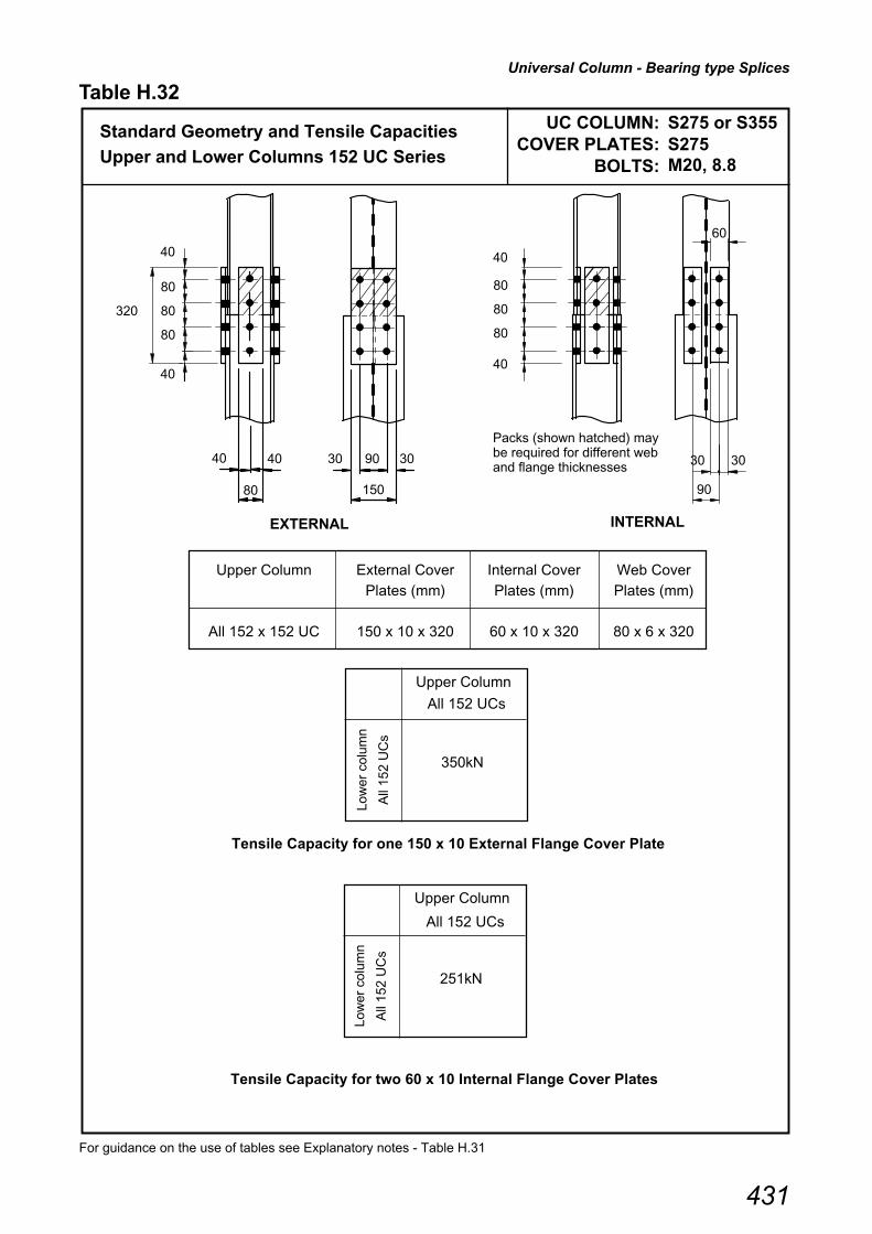
Universal Column - Bearing type Splices
431
UC COLUMN: S275 or S355COVER PLATES: S275
BOLTS:
For guidance on the use of tables see Explanatory notes - Table H.31
Standard Geometry and Tensile Capacities
Upper and Lower Columns 152 UC Series
Tensile Capacity for two 60 x 10 Internal Flange Cover Plates
Upper Column External Cover Internal Cover Web Cover
Plates (mm) Plates (mm) Plates (mm)
All 152 x 152 UC 150 x 10 x 320 60 x 10 x 320 80 x 6 x 320
Tensile Capacity for one 150 x 10 External Flange Cover Plate
Upper Column
All 152 UCs
350kN
EXTERNAL INTERNAL
Upper Column
All 152 UCs
251kN
80
80
80
40
90
30 30
80
40 40
150
30 90 30
320
40
80
80
40
60
80
Packs (shown hatched) may be required for different web and flange thicknesses
40
Table H.32
Low
er c
olum
n
All
152
UC
s
M20, 8.8
Low
er c
olum
n
All
152
UC
s

Universal Column - Bearing type Splices
432
UC COLUMN: S275 or S355COVER PLATES: S275
BOLTS:
For guidance on the use of tables see Explanatory notes - Table H.31
46 52 60 71 86
46 368 - - - -
52 368 368 - - -
60 368 368 368 - -
71 368 368 368 368 -
86 351 360 368 368 368
Upper Column (kg/m)
Upper Column External Cover Internal Cover Web CoverPlates (mm) Plates (mm) Plates (mm)
All 203 x 203 UC 200 x 10 x 440 80 x 10 x 440 120 x 8 x 150
Upper Column
All 203 UCs
368kN
Low
er c
olum
nA
ll 20
3 U
Cs
Standard Geometry and Tensile Capacities
Upper and Lower Columns 203 UC Series
Table H.32 Continued
M20, 8.8
Low
er c
olum
n
(kg/
m)
120
35 35
200
40 120 40
35
80
Packs (shown hatched) may be required for different web and flange thicknesses
50
35
150
120
40 40
40
140
80
40
140
80
Tensile Capacity (kN) for two 80 x 10 Internal Flange Cover Plates
Tensile Capacity (kN) for one 200 x 10 External Flange Cover Plate
EXTERNAL INTERNAL
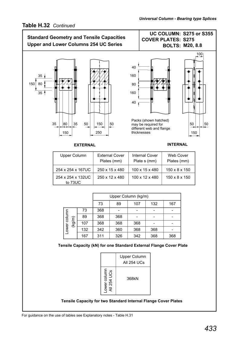
Universal Column - Bearing type Splices
433
UC COLUMN: S275 or S355COVER PLATES: S275
BOLTS:
For guidance on the use of tables see Explanatory notes - Table H.31
Upper Column External Cover Internal Cover Web CoverPlates (mm) Plate s (mm) Plates (mm)
254 x 254 x 167UC 250 x 15 x 480 100 x 15 x 480 150 x 8 x 150
254 x 254 x 132UC 250 x 12 x 480 100 x 12 x 480 150 x 8 x 150to 73UC
Upper Column
All 254 UCs
368kN
Standard Geometry and Tensile Capacities
Upper and Lower Columns 254 UC Series
Table H.32 Continued
M20, 8.8
Low
er c
olum
nA
ll 25
4 U
Cs
150
35 35
250
50 150 50
35
80
Packs (shown hatched) may be required for different web and flange thicknesses
80
35
150
150
50
160
50
40
80
160
40
100
73 89 107 132 167
73 368 - - - -
89 368 368 - - -
107 368 368 368 - -
132 342 360 368 368 -
167 311 326 342 368 368
Upper Column (kg/m)
Low
er c
olum
n
(kg/
m)
Tensile Capacity for two Standard Internal Flange Cover Plates
Tensile Capacity (kN) for one Standard External Flange Cover Plate
EXTERNAL INTERNAL
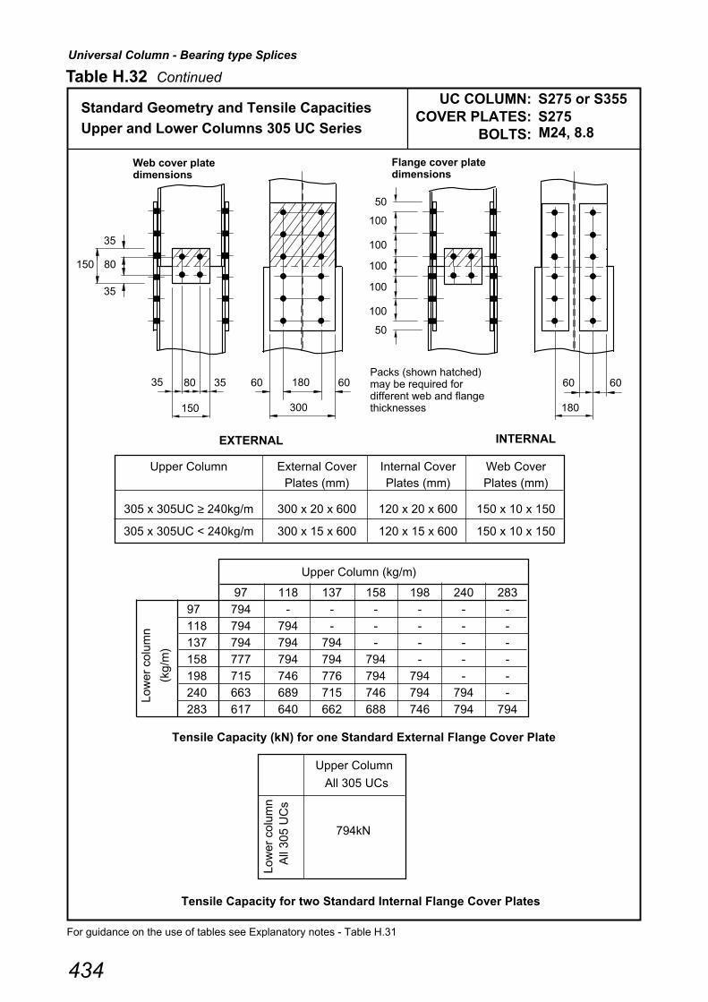
Universal Column - Bearing type Splices
434
UC COLUMN: S275 or S355COVER PLATES: S275
BOLTS:
For guidance on the use of tables see Explanatory notes - Table H.31
97 118 137 158 198 240 283
97 794 - - - - - -
118 794 794 - - - - -137 794 794 794 - - - -
158 777 794 794 794 - - -
198 715 746 776 794 794 - -240 663 689 715 746 794 794 -
283 617 640 662 688 746 794 794
Upper Column (kg/m)
Upper Column External Cover Internal Cover Web CoverPlates (mm) Plates (mm) Plates (mm)
305 x 305UC ≥ 240kg/m 300 x 20 x 600 120 x 20 x 600 150 x 10 x 150
305 x 305UC < 240kg/m 300 x 15 x 600 120 x 15 x 600 150 x 10 x 150
Upper Column
All 305 UCs
794kN
Low
er c
olum
nA
ll 30
5 U
Cs
Standard Geometry and Tensile Capacities
Upper and Lower Columns 305 UC Series
Table H.32 Continued
M24, 8.8Lo
wer
col
umn
(kg/
m)
Tensile Capacity for two Standard Internal Flange Cover Plates
Tensile Capacity (kN) for one Standard External Flange Cover Plate
EXTERNAL INTERNAL
150
35 35
300
60 180 60
35
80
80
35
150
180
6060
50
100
100
100
50
100
100
Packs (shown hatched) may be required for different web and flange thicknesses
Web cover plate dimensions
Flange cover plate dimensions

Universal Column - Bearing type Splices
435
UC COLUMN: S275 or S355COVER PLATES: S275
BOLTS:
For guidance on the use of tables see Explanatory notes - Table H.31
Upper Column External Cover Internal Cover Web CoverPlates (mm) Plates (mm) Plates (mm)
356 x 368 x 202UC 350 x 15 x 800 150 x 15 x 800 200 x 10 x 200
356 x 368UC < 202kg/m 350 x 12 x 800 150 x 12 x 800 200 x 10 x 200
Upper Column
All 356 x 368 UCs
794kN
Low
er c
olum
n
All
356
x 36
8
UC
s
Standard Geometry and Tensile Capacities
Upper and Lower Columns 356 x 368 UC Series
Table H.32 Continued
M24, 8.8
129 153 177 202
129 794 - - -
153 794 794 - -
177 794 794 794 -
202 778 794 794 794
Upper Column (kg/m)
Low
er c
olum
n
(kg/
m)
200
50
350
20075
50
100
Packs (shown hatched) may be required for different web and flange thicknesses
100
50
200
50 75
200
7575
50
150
150
50
150
150
100
150
Tensile Capacity for two Standard Internal Flange Cover Plates
Tensile Capacity (kN) for one Standard External Flange Cover Plate
EXTERNAL INTERNAL
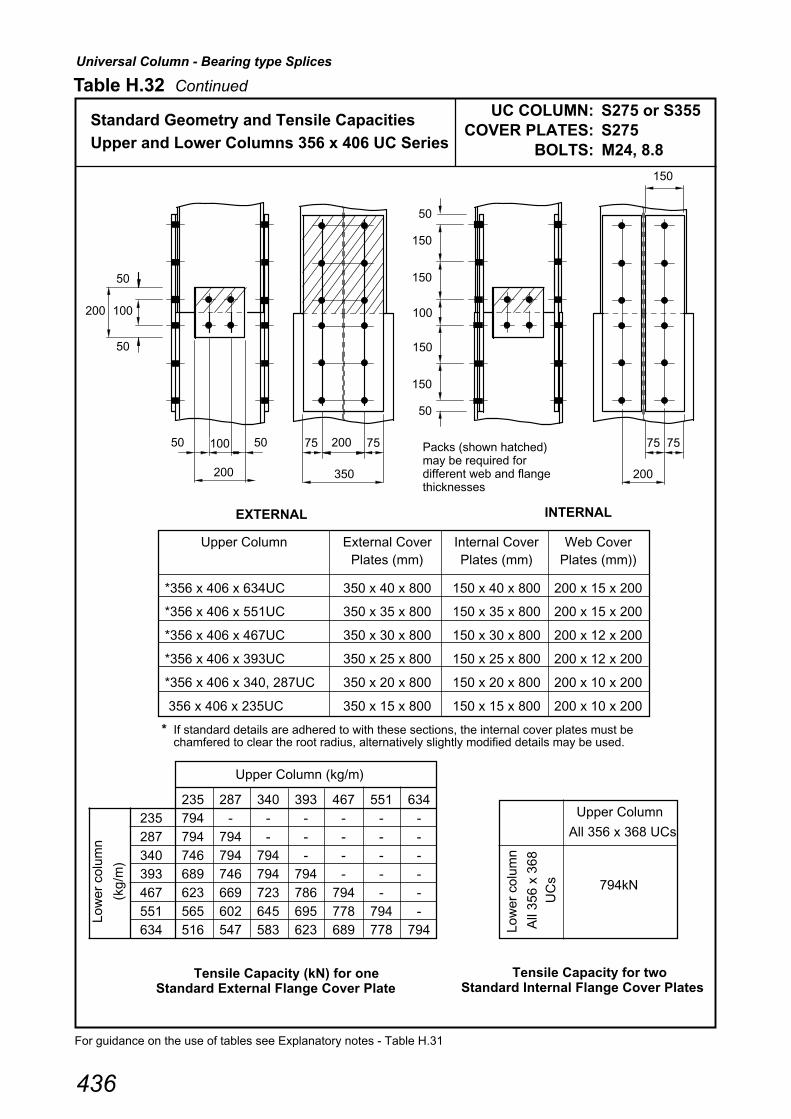
Universal Column - Bearing type Splices
436
UC COLUMN: S275 or S355COVER PLATES: S275
BOLTS:
For guidance on the use of tables see Explanatory notes - Table H.31
200
50
350
20075
50
100
Packs (shown hatched) may be required for different web and flange thicknesses
100
50
200
50 75
200
7575
50
150
150
50
150
150
100
150
Upper Column (kg/m)
235 287 340 393 467 551 634235 794 - - - - - -
287 794 794 - - - - -
340 746 794 794 - - - -393 689 746 794 794 - - -
467 623 669 723 786 794 - -
551 565 602 645 695 778 794 -634 516 547 583 623 689 778 794
Upper Column External Cover Internal Cover Web CoverPlates (mm) Plates (mm) Plates (mm))
*356 x 406 x 634UC 350 x 40 x 800 150 x 40 x 800 200 x 15 x 200
*356 x 406 x 551UC 350 x 35 x 800 150 x 35 x 800 200 x 15 x 200
*356 x 406 x 467UC 350 x 30 x 800 150 x 30 x 800 200 x 12 x 200
*356 x 406 x 393UC 350 x 25 x 800 150 x 25 x 800 200 x 12 x 200
*356 x 406 x 340, 287UC 350 x 20 x 800 150 x 20 x 800 200 x 10 x 200
356 x 406 x 235UC 350 x 15 x 800 150 x 15 x 800 200 x 10 x 200
* If standard details are adhered to with these sections, the internal cover plates must bechamfered to clear the root radius, alternatively slightly modified details may be used.
Upper Column
All 356 x 368 UCs
794kN
Low
er c
olum
n
All
356
x 36
8
UC
s
Table H.32 Continued
Standard Geometry and Tensile Capacities
Upper and Lower Columns 356 x 406 UC Series M24, 8.8
Low
er c
olum
n
(kg/
m)
Tensile Capacity for twoStandard Internal Flange Cover Plates
Tensile Capacity (kN) for oneStandard External Flange Cover Plate
EXTERNAL INTERNAL
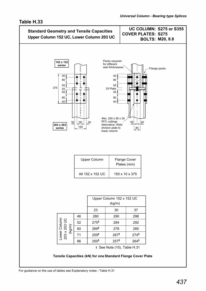
Universal Column - Bearing type Splices
437
UC COLUMN: S275 or S355COVER PLATES: S275
BOLTS:
For guidance on the use of tables see Explanatory notes - Table H.31
Upper Column Flange CoverPlates (mm)
All 152 x 152 UC 150 x 10 x 375
Upper Column 152 x 152 UC
(kg/m)
23 30 37
46 280 290 298
52 275‡ 284 292
60 269‡ 278 285
71 259‡ 267‡ 274‡
86 250‡ 257‡ 264‡
‡ See Note (10), Table H.31
Tensile Capacities (kN) for one Standard Flange Cover Plate
Low
er C
olum
n
203
x 20
3 U
C(k
g/m
)
Standard Geometry and Tensile Capacities
Upper Column 152 UC, Lower Column 203 UC
Table H.33
M20, 8.8
375
40
80
5525
40
80
55
30 90 30
150
40
80
5525 Plate
40
80
55
40 40
80
4No. 200 x 90 x 30 PFC cuttings Alternative: Weld division plate to lower column
Packs required for different web thicknesses
152 x 152 series
203 x 203 series
Flange packs

Universal Column - Bearing type Splices
438
UC COLUMN: S275 or S355COVER PLATES: S275
BOLTS:
For guidance on the use of tables see Explanatory notes - Table H.31
Upper Column Flange CoverPlates (mm)
All 203 x 203 UC 200 x 10 x 485
Tensile Capacities (kN) for one Standard Flange Cover Plate
Upper Column 203 x 203UC
(kg/m)
Low
er C
olum
n
254
x 25
4 U
C(k
g/m
)
Table H.33 Continued
Standard Geometry and Tensile Capacities
Upper Column 203 UC, Lower Column 254 UC M20, 8.8
485
40
140
5025
140
50
40 120 40
200
40
5025 Plate
35 35
120
4No. 90 x 90 x 8 angles Bolts at 50 B.M Alternative: Weld division plate to lower column
Packs required for different web thicknesses
203 x 203 series
254 x 254 series
40
50
50
40
Flange packs
46 52 60 71 86
73 280 285 292 304 -
89 269‡ 274‡ 280 292 305
107 259‡ 264‡ 269‡ 280 292
132 245‡ 249‡ 254‡ 264‡ 274‡
167 229‡ 233‡ 237‡ 245‡ 254‡
‡ See Note (10), Table H.31

Universal Column - Bearing type Splices
439
UC COLUMN: S275 or S355COVER PLATES: S275
BOLTS:
For guidance on the use of tables see Explanatory notes - Table H.31
Tensile Capacities (kN) for one Standard Flange Cover Plate
73 89 107 132 167
97 275‡ 286 - - -
118 264‡ 274‡ 285 - -
137 255‡ 264‡ 275‡ 292 -
158 245‡ 254‡ 264‡ 280 -
198 229‡ 237‡ 245‡ 259‡ 280
240 215‡ 222‡ 229‡ 241‡ 259‡
283 202‡ 208‡ 215‡ 225‡ 241‡
‡ See Note (10), Table H.31
Upper Column 254 x 254UC(kg/m)
Upper Column Flange Cover
Plates (mm)
254 x 254UC 167kg/m 250 x 15 x 525
254 x 254UC < 167kg/m 250 x 12 x 525
Low
er C
olum
n
305
x 30
5 U
C(k
g/m
)
Table H.33 Continued
Standard Geometry and Tensile Capacities
Upper Column 254 UC, Lower Column 305 UC M20, 8.8
525
40
160
5025
160
50
50 150 50
250
40
5025 Plate
35 35
150
4No. 90 x 90 x 8 angles Bolts at 50 B.M Alternative: Weld division plate to lower column
Packs required for different web thicknesses
254 x 254 series
305 x 305 series
40
50
80
40
Flange packs

Universal Column - Bearing type Splices
440
UC COLUMN: S275 or S355COVER PLATES: S275
BOLTS:
For guidance on the use of tables see Explanatory notes - Table H.31
Upper Column Flange Cover
Plates (mm)
305 x 305UC ≥ 240kg/m 300 x 20 x 635
305 x 305UC < 240kg/m 300 x 15 x 635
97 118 137 158 198 240 283
129 651 676 - - - - -
153 628 655 675 - - - -
177 607 629 651 676 - - -
202 587‡ 608 628 652 703 - -
‡ See Note (10), Table H.31
Tensile Capacities (kN) for one Standard Flange Cover Plate
Upper Column 305 x 305UC
(kg/m)
Low
er C
olum
n
356
x 36
8 U
C(k
g/m
)
Table H.33 Continued
Standard Geometry and Tensile Capacities
Upper Column 305 UC, Lower Column 356 UC M24, 8.8
635
50
100
5525
60 180 60
300
45
5525 Plate
35 35
150
4No. 100 x 100 x 10 angles Bolts at 55 B.M Alternative: Weld division plate to lower column
Packs required for different web thicknesses
305 x 305 series
356 x 368 series
45
55
80
100
50
100
55
100
Flange packs
Hollow Section Tension Splices
441
Table H.34
Explanatory notes - HOLLOW SECTION TENSION SPLICES
Use of capacity tables.
The following notes refer to the suffix numbers given at the top of the column descriptions for Tables H.36 to H.38for hollow section tension splices.The check numbers refer to those listed in Section 7.7 and 7.8 Design procedures.
The connection details are suitable for members in tension.
(1) DETAILING
• All detailing requirements of CHECK 1 from Sections 7.7 and 7.8 are adhered to.
• The capacity tables are based on the standard connection details that are given in Table H.35 for circular,
square and rectangular hollow sections.
• Dimension e1 has been set ≥ 51 mm to allow sufficient tightening access when using a torque wrench.
(See Table H.62 where clearance c = 51 mm for M24 bolts
(2) TENSION CAPACITY OF THE CONNECTION
• The tables are based on M24 grade 8.8 bolts and S275 plates.
• Tension capacities tabulated are valid for both S275 and S355 members.
• The tension capacities are conservatively based on the dimensions of the heaviest section available for the
given outside dimensions. Lighter sections will have higher connection capacities than those tabulated.
• The tension capacities are based on the minimum of CHECKS 2, 3 and 4 from Section 7.7 for square and
rectangular hollow sections and from Section 7.8 for circular hollow sections.
(3) CRITICAL DESIGN CHECK
• The critical design check column indicates whether it is CHECK 2 (Complete end plate yielding) or CHECK 3
(Bolt failure with end plate yielding) which controls the connection capacity.

Hollow Section Tension Splices
442
Table H.35
HOLLOW SECTION TENSION SPLICES
Standard details used in Capacity Tables
CIRCULAR HOLLOW SECTION SPLICE DETAILS
e2 = 50 mm
e1 ≥ 51 mm
SQUARE AND RECTANGULAR HOLLOW SECTION SPLICE DETAILS
e2 = 50 mm
e1 ≥ 51 mm
t p t pp
D pD
t
N = total number of bolts Bolts:M24 grade 8.8 Plate:S275
t
t p t p
B D
N/2 bolts at 90 mm spacing
B p
D p
N = total number of bolts Bolts:M24 grade 8.8 Plate:S275
3 e = 50 mm 3 e = 50 mm

������ ����� ��� �� �����
���� ���� ����
� ����� ����
�������� �� ��� ���� ���
������� ��� � ���� ��� ���������
������
������� �� �������
���������
������� ��������� ���� ������� ������������
������
� � � �� �� �� �������
���
�� �� �� �� �� ��
����� � ��� ��� �� �� �� ��� �
����� � ��� ��� �� �� �� ��� �
����� � ��� ��� �� �� �� ��� � �
����� � ��� ��� �� �� �� ��� �
����� � ��� ��� �� �� �� ��� �
����� � ��� ��� �� �� �� � � �
����� � ��� ��� �� �� �� ��� � �
����� � ��� ��� �� �� �� ��� �
����� � ��� ��� �� �� �� ��� �
����� � ��� ��� �� �� �� ��� � �
����� ��� ��� �� �� �� ���� � �
����� � ��� ��� �� �� �� ��� �
����� � ��� ��� �� �� �� ��� �
����� �� ��� �� �� �� ���� � �
���� � ��� ��� �� �� �� ��� �
���� � ��� ��� �� �� �� ��� �
���� ��� ��� �� �� �� ���� � �
���� �� ��� ��� �� �� �� ���� � �
��� � � � ��� �� �� �� ��� �
��� ��� ��� �� �� �� ��� �
��� �� ��� ��� �� �� �� �� � �
��� �� �� ��� �� �� �� ���� �
���� � ��� � � �� �� �� ��� �
���� ��� � � �� �� �� ��� �
���� �� ��� � � �� �� �� ���� � �
���� �� �� � � �� �� �� �� � � �
���� ��� ��� �� �� �� ���� �
���� �� ��� ��� �� �� �� ���� �
���� �� ��� ��� �� �� �� ���� �
���� �� �� ��� �� �� �� ���� �
����� ��� ��� �� �� �� ���� �
����� �� ��� ��� �� �� �� ���� �
����� �� ��� ��� �� �� �� ���� �
����� �� ��� ��� �� �� �� ���� �
���� �� ��� ��� �� �� �� ���� �
���� �� ��� ��� �� �� �� ���� �
���� �� ��� ��� �� �� �� ���� �
���� �� ��� �� �� �� ���� �
���� �� ��� ��� �� �� �� ���� �
���� �� ��� ��� �� �� �� ���� �
���� � ��� ��� �� �� �� ���� �
���� �� � ��� �� �� �� �� � �
��� ������ ����� ��� �� �� �� �� �������� �� �� � � �� ����
��� ��� �� �� �� �� �� � ��� � ���� � ���� ���� � � �� ����
� ��� ! "���� � � ���# ������ � ��� � ��� $%&� ������
' ��� ! "���� � � ���# ������ � ��� � ��� $%&� �� $��� ������
����� �� �� �� ��������
������� �� ����
��
������ ������
�������
���������
���
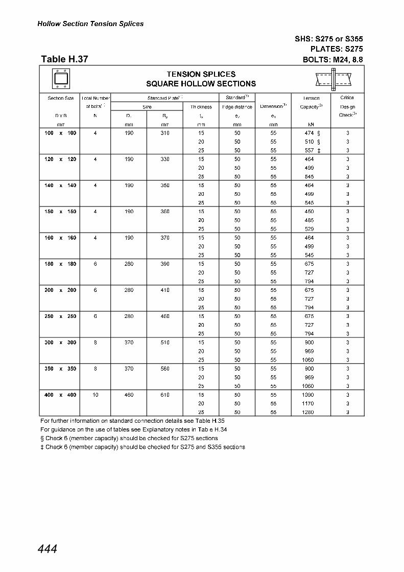
������ ����� ��� �� �����
���� ���� ����
� ����� ����
��������� �� ��� ���� ���
������� �� � ��� � ���� ���������
������
�� �������
��������� ���� ������� ������������
������
� ! � � �� �� �� �� �������
���
�� �� �� �� �� ��
��� � ��� � ��� ��� �� �� �� ��� �
��� � ��� � ��� ��� �� �� �� ��� �
��� � ��� � ��� ��� �� �� �� ��� � �
�� � �� � ��� ��� �� �� �� ��� �
�� � �� � ��� ��� �� �� �� ��� �
�� � �� � ��� ��� �� �� �� ��� �
��� � ��� � ��� ��� �� �� �� ��� �
��� � ��� � ��� ��� �� �� �� ��� �
��� � ��� � ��� ��� �� �� �� ��� �
�� � �� � ��� ��� �� �� �� ��� �
�� � �� � ��� ��� �� �� �� � � �
�� � �� � ��� ��� �� �� �� ��� �
��� � ��� � ��� ��� �� �� �� ��� �
��� � ��� � ��� ��� �� �� �� ��� �
��� � ��� � ��� ��� �� �� �� ��� �
��� � ��� � � � ��� �� �� �� ��� �
��� � ��� � � � ��� �� �� �� ��� �
��� � ��� � � � ��� �� �� �� ��� �
�� � �� � � � ��� �� �� �� ��� �
�� � �� � � � ��� �� �� �� ��� �
�� � �� � � � ��� �� �� �� ��� �
� � � � � � ��� �� �� �� ��� �
� � � � � � ��� �� �� �� ��� �
� � � � � � ��� �� �� �� ��� �
��� � ��� ��� ��� �� �� �� ��� �
��� � ��� ��� ��� �� �� �� ��� �
��� � ��� ��� ��� �� �� �� ���� �
�� � �� ��� ��� �� �� �� ��� �
�� � �� ��� ��� �� �� �� ��� �
�� � �� ��� ��� �� �� �� ���� �
��� � ��� �� ��� ��� �� �� �� ���� �
��� � ��� �� ��� ��� �� �� �� ���� �
��� � ��� �� ��� ��� �� �� �� �� � �
��� ������ ����� ��� �� �� �� �� �������� �� �� � � �� ����
��� ��� �� �� �� �� �� � ��� � ���� � ���� ���� � � �� ����
� ��� ! "���� � � ���# ������ � ��� � ��� $%&� ������
' ��� ! "���� � � ���# ������ � ��� � ��� $%&� �� $��� ������
��
������� �� ����
������ �� �� ��������
�� � ���������
������ ������
�������
���

������ ����� ��� �� �����
���� ���� ����
� ����� ����
��������� �� ��� ���� ���
������� �� � ��� � ���� ���������
������
�� �������
��������� ���� ������� ������������
������
� ! � � �� �� �� �� �������
���
�� �� �� �� �� ��
�� � ��� � � � ��� �� �� �� ��� �
�� � ��� � � � ��� �� �� �� ��� �
�� � ��� � � � ��� �� �� �� �� �
�� � �� � � � ��� �� �� �� ��� �
�� � �� � � � ��� �� �� �� ��� �
�� � �� � � � ��� �� �� �� �� �
�� � �� � � � ��� �� �� �� ��� �
�� � �� � � � ��� �� �� �� ��� �
�� � �� � � � ��� �� �� �� �� �
� � ��� � � � ��� �� �� �� ��� �
� � ��� � � � ��� �� �� �� ��� �
� � ��� � � � ��� �� �� �� �� �
� � �� � � � ��� �� �� �� ��� �
� � �� � � � ��� �� �� �� ��� �
� � �� � � � ��� �� �� �� ��� �
��� � ��� ��� ��� �� �� �� ��� �
��� � ��� ��� ��� �� �� �� ���� �
��� � ��� ��� ��� �� �� �� ���� �
��� � �� ��� ��� �� �� �� ��� �
��� � �� ��� ��� �� �� �� ��� �
��� � �� ��� ��� �� �� �� ���� �
��� � �� �� ��� ��� �� �� �� ���� �
��� � �� �� ��� ��� �� �� �� ���� �
��� � �� �� ��� ��� �� �� �� ���� �
�� � � �� ��� ��� �� �� �� ���� �
�� � � �� ��� ��� �� �� �� ���� �
�� � � �� ��� ��� �� �� �� ���� �
�� � ��� �� ��� ��� �� �� �� ���� �
�� � ��� �� ��� ��� �� �� �� ���� �
�� � ��� �� ��� ��� �� �� �� ���� �
��� ������ ����� ��� �� �� �� �� �������� �� �� � � �� ����
��� ��� �� �� �� �� �� � ��� � ���� � ���� ���� � � �� ����
� ��� ! "���� � � ���# ������ � ��� � ��� $%&� ������
�� �
������ ������
������� �� ����
�������� �� �� �� ��������
��
�������
���������
���

Column Bases
446
Table H.39
Explanatory notes - COLUMN BASES
Use of capacity tables.
The following notes refer to the suffix numbers given at the top of the column descriptions for Table H.41 foruniversal column bases and Tables H.42 to H.44 for hollow section column bases. The check numbers refer to thoselisted in Section 8.5, Design procedures.
(1) BASE PLATE SIZE
See Table H.40 for standard base plate details.
(2) AXIAL CAPACITY OF BASE PLATE
• The capacities tabulated are axial compression capacities based on the minimum capacity fromCHECKS 1 and 2 in Section 8.5 (Effective area method).
• The capacities are conservatively based on the dimensions of the lightest section available for theoutside dimensions of the section. Heavier sections will have higher base plate capacities than thosetabulated.
• Capacities are tabulated for a range of cube strengths of bedding materials/foundation concrete.The capacity based on the cube strength of the weaker material should be used.
• The capacities calculated are for S275 base plates.
• Base plate capacities tabulated are valid for both S275 and S355 columns.

Column Bases
447
Table H.40
COLUMN BASES
Standard details used in Capacity Tables
UNIVERSAL COLUMN BASE PLATE DETAILS
HOLLOW SECTION COLUMN BASE PLATE DETAILS
Dp
Bp
t p
T
Dp
Bp
t
t p
Dp
Bp
t
t p
t
t p
Bp
Dp
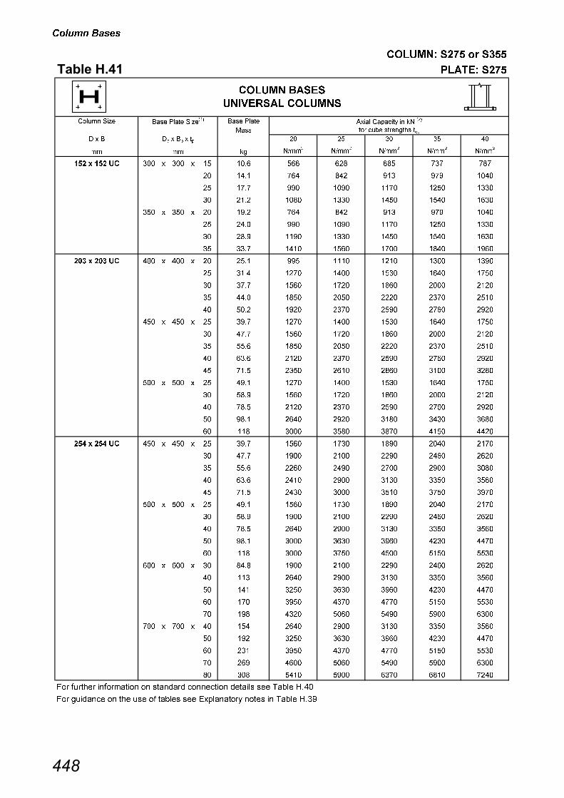
������ ��
������� �� � ���
�������� ������ ��
������ �� � �� �� �� ����� � �� �� �� �� � � � ��� � ��
���
� �� ��� ���� ��������� ���
� � � �� � �� � �� � �! " "! #
�� �� �� �$���
�$���
�$���
�$���
�$���
��� � ��� �� ��� � ��� � �� ���� ��� �� �� �
��� � ��� � �� ���� �� �� ��� �� ����
��� � ��� � �� �� ��� ���� ��� ���� ����
��� � ��� � �� ���� ��� ���� ���� ���� ����
��� � ��� � �� ���� �� �� ��� �� ����
��� � ��� � �� ���� ��� ���� ��� ���� ����
��� � ��� � �� ��� ���� ���� ���� ���� ����
��� � ��� � �� ��� ���� ���� ��� ��� ����
�� � �� �� ��� � ��� � �� ���� ��� ���� ���� ���� ����
��� � ��� � �� ���� ��� ���� ���� ���� ���
��� � ��� � �� �� ���� ��� ��� ���� ����
��� � ��� � �� ���� ��� ���� ���� ��� ����
��� � ��� � �� ���� ���� ��� ���� ��� ����
��� � ��� � �� ��� ��� ���� ���� ���� ���
��� � ��� � �� �� ���� ��� ��� ���� ����
��� � ��� � �� ���� ��� ���� ���� ��� ����
��� � ��� � �� ���� ���� ��� ���� ��� ����
��� � ��� � �� ��� ���� ���� ��� ���� ���
��� � ��� � �� ���� ��� ���� ���� ���� ���
��� � ��� � �� ��� ���� ��� ��� ���� ����
��� � ��� � �� �� ���� ��� ���� ��� ����
��� � ��� � �� ��� ���� ���� ��� ���� ���
��� � ��� � �� �� ���� ��� �� ���� ����
�� � �� �� ��� � ��� � �� ��� ���� ��� ��� ���� ���
��� � ��� � �� �� ���� ���� ���� ���� ����
��� � ��� � �� ���� ���� ���� ��� ���� ���
��� � ��� � �� ���� ���� ���� ���� ���� ����
��� � ��� � �� ��� ���� ���� ���� ��� ���
��� � ��� � �� ���� ���� ��� ��� ���� ���
��� � ��� � �� ��� ���� ���� ���� ���� ����
��� � ��� � �� �� ���� ���� ���� ���� ����
��� � ��� � �� ��� ���� ���� ���� ���� ���
��� � ��� � �� �� ���� ��� ���� ���� ����
��� � ��� � �� �� ���� ���� ���� ���� ����
��� � ��� � �� ��� ���� ���� ���� ���� ����
��� � ��� � �� ��� ���� ���� ���� ���� ���
��� � ��� � �� �� ���� ��� �� ���� ����
��� � ��� � � �� ���� ���� ���� ���� ����
�� � �� � �� ��� ���� ���� ���� ���� ����
�� � �� � �� ��� ���� ���� ���� ���� ���
�� � �� � �� ��� ���� ��� �� ���� ����
�� � �� � � ��� ���� ���� ���� ���� ����
�� � �� � � �� ���� ���� ��� ��� ���
��� ������ ����� ��� �� �� �� �� �������� �� �� � � �� ����
��� ��� �� �� �� �� �� � ��� � ���� � ���� ���� � � �� ����
������ ���
�������� ������
���

������ ��
������� �� � ���
������������������� ������ ��
������ �� � �� �� �� ����� � �� �� �� �� � � � ��� � ��
���
� �� ��� ���� ��������� ���� � � �� � �� � �� � �! " "! #
�� �� �� �$���
�$���
�$���
�$���
�$���
�� � �� �� ��� � ��� � �� ���� ��� ���� ���� ���� ����
��� � ��� � �� ��� ���� ��� ��� ���� ����
��� � ��� � �� �� ��� ��� ��� ���� ����
��� � ��� � �� ��� ��� ���� ���� ��� ����
��� � ��� � �� �� ���� ��� ���� ���� ���
��� � ��� � �� �� ���� ��� ��� ���� ����
��� � ��� � �� ��� ��� ���� ��� ���� ����
��� � ��� � �� ��� ��� ��� ���� ���� ����
��� � ��� � �� �� ���� ���� ��� ��� ����
��� � ��� � � �� ���� ���� ��� ��� ���
�� � �� � �� ��� ��� ���� ��� ���� ����
�� � �� � �� ��� ��� ��� ���� ���� ����
�� � �� � �� ��� ��� ���� ��� ��� ����
�� � �� � � ��� ���� ���� ��� ��� ���
�� � �� � � �� �� ���� ��� ��� ��
�� � �� � �� ��� ��� ���� ��� ���� ����
�� � �� � �� ��� ��� ��� ���� ���� ����
�� � �� � �� ��� ��� ���� ��� ��� ����
�� � �� � � ��� ���� ���� ��� ��� ���
�� � �� � � ��� ��� ���� ��� ��� ��
�� � �� � �� ��� ��� �� �� �� ���
�� � �� �� ��� � ��� � �� �� ���� ���� ���� ���� ���
��� � ��� � �� ��� ��� ���� ���� ���� ����
��� � ��� � �� ��� ���� ���� ��� ��� ����
��� � ��� � �� �� ���� ���� ���� ���� ��
��� � ��� � � �� ���� ���� ���� �� ���
�� � �� � �� ��� ��� ���� ���� ���� ����
�� � �� � �� ��� ���� ���� ��� ��� ����
�� � �� � �� ��� ���� ���� ���� ��� ��
�� � �� � � ��� �� ��� �� ��� ���
�� � �� � � �� �� ��� � ���� �����
�� � �� � �� ��� ��� ���� ���� ���� ����
�� � �� � �� ��� ���� ���� ��� ��� ����
�� � �� � �� ��� ���� ���� ���� ��� ��
�� � �� � � ��� ���� ��� �� ��� ���
�� � �� � � ��� ��� ��� �� ���� �����
�� � �� � �� ��� �� �� ��� ����� �����
��� ������ ����� ��� �� �� �� �� �������� �� �� � � �� ����
��� ��� �� �� �� �� �� � ��� � ���� � ���� ���� � � �� ����
������ ���
�������� ������
���

������ ��
������� �� � ���
������������������� ������ ��
������ �� � �� �� �� ����� � �� �� �� �� � � � ��� � ��
���
� �� ��� ���� ��������� ���� � � �� � �� � �� � �! " "! #
�� �� �� �$���
�$���
�$���
�$���
�$���
�� � �� �� �� � �� � �� ��� ���� ��� �� ���� ����
���� � ����� �� � �� � �� ��� ��� ���� ��� ���� ��
�� � �� � �� ��� ���� ���� �� ��� ��
�� � �� � � ��� ��� ��� ��� ��� ����
�� � �� � � ��� ��� ��� ���� ����� �����
�� � �� � �� ��� �� ���� ����� ����� �����
��� � ��� � �� �� ��� ���� ��� ���� ��
��� � ��� � �� �� ���� ���� �� ��� ��
��� � ��� � � ��� ��� ��� ��� ��� ����
��� � ��� � � ��� � ��� ���� ����� �����
��� � ��� � �� �� ��� ��� ����� ����� �����
��� � ��� � ��� ��� ���� ���� ���� ����� �����
���� � ���� � �� ��� ��� ���� ��� ���� ��
���� � ���� � �� �� ���� ���� �� ��� ��
���� � ���� � � ��� ��� ��� ��� ��� ����
���� � ���� � � �� � ��� ���� ����� �����
���� � ���� � �� � ��� ��� ����� ����� �����
���� � ���� � ��� � ��� ���� ���� ����� �����
���� � ���� � ��� �� ����� ����� ����� ����� �����
���� � ���� � ��� ��� ���� ���� ����� ����� ����
�� � �� �� ��� � ��� � �� �� ���� ��� ���� ��� ��
�� ����� ��� � ��� � �� �� ���� ��� �� �� ���
��� � ��� � � ��� �� ��� ��� ���� �����
��� � ��� � � ��� �� ��� ����� ����� ����
��� � ��� � �� �� ���� ����� ����� ����� �����
��� � ��� � ��� ��� ��� ����� ����� ����� �����
���� � ���� � �� ��� ���� ��� ���� ��� ��
���� � ���� � �� �� ���� ��� �� �� ���
���� � ���� � � ��� �� ��� ��� ���� �����
���� � ���� � � �� �� ��� ����� ����� ����
���� � ���� � �� � ���� ����� ����� ����� �����
���� � ���� � ��� � ����� ����� ����� ����� �����
���� � ���� � ��� �� ����� ����� ����� ����� �����
���� � ���� � ��� ��� ����� ����� ���� ���� ����
���� � ���� � � ��� �� ��� ��� ���� �����
���� � ���� � � �� �� ��� ����� ����� ����
���� � ���� � �� �� ���� ����� ����� ����� �����
���� � ���� � ��� ��� ����� ����� ����� ����� �����
���� � ���� � ��� ���� ����� ����� ����� ����� �����
���� � ���� � ��� ���� ����� ����� ���� ���� ����
���� � ���� � � �� �� ��� ����� ����� ����
���� � ���� � �� ���� ���� ����� ����� ����� �����
���� � ���� � ��� ���� ����� ����� ����� ����� �����
���� � ���� � ��� ��� ����� ����� ���� ���� ����
���� � ���� � ��� ��� ����� ����� ���� ���� ����
���� � ���� � ��� ��� ����� ���� ���� ����� �����
��� ������ ����� ��� �� �� �� �� �������� �� �� � � �� ����
��� ��� �� �� �� �� �� � ��� � ���� � ���� ���� � � �� ����
������ ���
�������� ������
���

������ ��
������� �� � ���
�������� ������ ��
���� ����� ����� ���� ����� � �� ������� � ��
���
���� ��� ���� ��������� ���
�� �� �� �� � !� ! "�
## �� �$##�
�$##�
�$##�
�$##�
�$##�
����� � ��� � ��� � �� ���� � �� ��� �� �
����� � ��� � ��� � �� ��� � ��� ��� �� ���
����� � ��� � ��� � �� �� �� ��� ��� �� �
����� � ��� � ��� � �� ���� �� �� �� �� ��
����� � ��� � ��� � �� ��� ��� �� ��� �� ����
����� � �� � �� � �� ���� �� �� �� �� ��
����� � �� � �� � �� ���� ��� ��� ��� �� ����
����� � �� � �� � � ���� ��� ��� ���� ���� ����
����� � �� � �� � �� ���� �� �� �� �� ��
����� � �� � �� � �� ���� ��� ��� ��� �� ����
����� � �� � �� � � ���� �� ��� ���� ���� ����
����� � ��� � ��� � �� �� �� �� �� ��� ��
����� � ��� � ��� � �� ���� � �� ��� �� ����
����� � ��� � ��� � �� ��� ��� ��� ��� ��� ����
����� � �� � �� � �� ��� ��� �� �� ��� ��
����� � �� � �� � �� ���� �� ��� �� �� ����
����� � �� � �� � �� ���� �� ��� ���� ��� ����
����� � �� � �� � � ���� ��� ��� ��� ��� ����
����� � �� � �� � �� ���� �� ��� �� �� ����
����� � �� � �� � �� ���� � ��� ���� ��� ����
����� � �� � �� � � ���� ��� ��� ���� ��� ����
����� � �� � �� � � �� ���� ��� ���� ��� ����
����� � ��� � ��� � �� ���� �� ��� �� �� ����
����� � ��� � ��� � �� ��� � ��� ���� ��� ����
����� � ��� � ��� � � ��� ��� ��� ���� ��� ����
����� � ��� � ��� � � ���� ���� ��� ���� ��� ����
����� � ��� � ��� � �� ���� ���� ���� ��� ���� ����
����� � �� � �� � �� ��� �� ��� �� �� ���
����� � �� � �� � �� ���� ��� ��� ��� ���� ���
����� � �� � �� � �� ���� �� ���� ���� ��� ����
����� � �� � �� � � ���� ��� ���� ���� ���� ���
����� � �� � �� � �� ���� ��� ��� ��� ���� ���
����� � �� � �� � �� ���� ���� ���� ���� ��� ����
����� � �� � �� � � ���� ���� ��� ���� ���� ����
����� � ��� � ��� � �� ���� ��� ��� ��� ���� ���
����� � ��� � ��� � �� ��� ���� ���� ���� ��� ����
����� � ��� � ��� � � ��� ���� ��� ���� ���� ����
����� � ��� � ��� � � ���� ��� ���� ���� ���� ����
����� � ��� � ��� � �� ���� ���� ���� ���� ���� ����
����� � ��� � ��� � �� ��� ���� ���� ���� ��� ����
����� � ��� � ��� � � ���� ���� ��� ���� ���� ����
����� � ��� � ��� � � ��� ��� ���� ���� ���� ����
����� � ��� � ��� � �� � ���� ���� ���� ���� ����
����� � ��� � ��� � �� ���� ���� ��� ���� ��� ����
��� ������ ����� ��� �� �� �� �� �������� �� �� � � �� ����
��� ��� �� �� �� �� �� � ��� � ���� � ���� ���� � � �� ����
����#� ��
�
##
������ ���
�������� ������ ������
���

������ ��
������� �� � ���
������������������� ������ ��
���� ����� ����� ���� ����� � �� ������� � ��
���
���� ��� ���� ��������� ���
�� �� �� �� � !� ! "�
## �� �$##�
�$##�
�$##�
�$##�
�$##�
����� � �� � �� � �� ���� �� ��� ��� ��� ���
����� � �� � �� � �� ���� ���� ���� ���� ���� ��
����� � �� � �� � � ���� ��� ���� ��� ���� ����
����� � �� � �� � � �� ���� ��� ��� ���� ����
����� � ��� � ��� � �� ���� �� ��� ��� ��� ���
����� � ��� � ��� � �� ��� ���� ���� ���� ���� ��
����� � ��� � ��� � � ��� ��� ���� ��� ���� ����
����� � ��� � ��� � � ���� ���� ��� ���� ���� ����
����� � ��� � ��� � �� ���� ���� ���� ���� ��� ���
����� � ��� � ��� � �� ��� ���� ���� ���� ���� ��
����� � ��� � ��� � � ���� ��� ���� ��� ���� ����
����� � ��� � ��� � � ��� ���� ��� ���� ���� ����
����� � ��� � ��� � �� � ���� ���� ���� ��� ���
����� � ��� � ��� � �� ���� ���� ���� ��� �� ����
����� � ��� � ��� � �� ���� ���� ���� ���� ���� ��
����� � ��� � ��� � � ���� ��� ���� ��� ���� ����
����� � ��� � ��� � �� ���� ���� ���� ���� ��� ���
����� � ��� � ��� � �� ���� ���� ��� ��� ���� ���
����� � ��� � ��� � � ��� �� ���� �� ��� ��
�� � ��� � ��� � �� ���� ��� ���� ���� ��� ����
�� � ��� � ��� � �� ��� ���� ��� ���� ���� ����
�� � ��� � ��� � � ��� ��� ���� ���� ���� ����
�� � ��� � ��� � � ���� ���� ���� ���� ��� ����
�� � ��� � ��� � �� ���� ���� ���� ���� ��� ���
�� � ��� � ��� � �� ��� ���� ��� ���� ���� ����
�� � ��� � ��� � � ���� ���� ���� ���� ���� ����
�� � ��� � ��� � � ��� ��� ���� ���� ��� ����
�� � ��� � ��� � �� � ���� ���� ���� ��� ���
�� � ��� � ��� � �� ���� ���� ��� ���� ���� ���
�� � ��� � ��� � �� ���� ���� ��� ���� ���� ����
�� � ��� � ��� � � ���� ���� ���� ���� ���� ����
�� � ��� � ��� � �� ���� ���� ���� ���� ��� ���
�� � ��� � ��� � �� ���� �� ���� ��� �� ���
�� � ��� � ��� � � ��� �� ���� �� ��� ����
�� � �� � �� � � ���� ���� ���� ���� ���� ����
�� �� ���� ���� ���� ��� ���
�� � �� � �� � �� ��� ��� ���� ��� �� ���
��� ������ ����� ��� �� �� �� �� �������� �� �� � � �� ����
��� ��� �� �� �� �� �� � ��� � ���� � ���� ���� � � �� ����
����#� ��
�
##
������ ���
�������� ������ ������
���
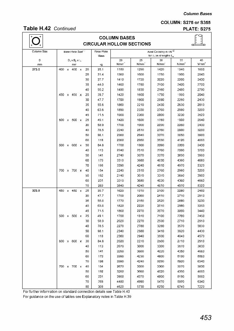
������ ��
������� �� � ���
������������������� ������ ��
���� ����� ����� ���� ����� � �� ������� � ��
���
���� ��� ���� ��������� ���
�� �� �� �� � !� ! "�
## �� �$##�
�$##�
�$##�
�$##�
�$##�
����� � ��� � ��� � �� ���� ���� ���� ���� ���� ���
����� � ��� � ��� � �� ��� �� ��� ���� ���� ����
����� � ��� � ��� � � ��� ���� ���� ���� ��� ���
����� � ��� � ��� � � ���� ��� ���� ���� ���� ����
����� � ��� � ��� � �� ���� ���� ��� ��� ���� ����
����� � ��� � ��� � �� ��� ���� ��� ���� ���� ����
����� � ��� � ��� � � ���� ���� ���� ���� ��� ���
����� � ��� � ��� � � ��� ��� ���� ��� �� ����
����� � ��� � ��� � �� � ���� �� ��� ���� ���
����� � ��� � ��� � �� ���� ���� �� ���� �� ���
����� � ��� � ��� � �� ���� ���� ��� ���� ���� ����
� ���� ���� ���� ���� ��� ���
����� � ��� � ��� � �� ���� ���� ���� ��� ���� ���
����� � ��� � ��� � �� ���� �� ���� �� �� ���
����� � ��� � ��� � � ��� �� ���� �� ���� ��
����� � �� � �� � � ���� ���� ���� ���� ��� ���
����� � �� � �� � �� �� ���� ���� ��� ���� ���
����� � �� � �� � �� ��� ���� ��� �� �� ���
����� � �� � �� � � ��� �� �� ��� �� ��
����� � �� � �� � �� ��� �� ���� ��� ���� ���
����� � ��� � ��� � �� ��� ���� ���� ��� ���� ���
����� � ��� � ��� � �� ��� ���� ��� �� �� ���
����� � ��� � ��� � � �� �� �� ��� �� ��
����� � ��� � ��� � �� �� ��� ���� ��� ���� ���
����� � ��� � ��� � �� ��� ��� ���� ���� ���� ����
����� � ��� � ��� � � ���� ���� ��� ���� ���� ����
����� � ��� � ��� � � ��� ���� ���� ���� ���� ��
����� � ��� � ��� � �� � ���� ���� ��� ���� ��
����� � ��� � ��� � �� ���� ��� ���� ��� �� ���
����� � ��� � ��� � �� ���� ���� ���� ���� ���� ����
����� � ��� � ��� � � ���� ���� ���� ���� ���� ����
����� � ��� � ��� � �� ���� ���� ���� ��� ��� ��
����� � ��� � ��� � �� ���� ��� ���� ��� ��� ���
����� � ��� � ��� � � ��� �� ���� ��� ���� ����
����� � �� � �� � � ���� ���� ���� ���� ���� ����
�� �� ��� ��� �� ��� ��
����� � �� � �� � �� ��� �� � ���� ��� ��
����� � �� � �� � � ��� �� ��� ���� ���� ���
����� � �� � �� � �� ��� �� ���� ���� ���� ��
����� � ��� � ��� � �� ��� ��� ��� �� ��� ��
����� � ��� � ��� � �� ��� �� � ���� ��� ��
����� � ��� � ��� � � �� ��� ��� ���� ���� ���
����� � ��� � ��� � �� �� ���� ���� ���� ���� ��
����� � ��� � ��� � �� �� ��� ��� ��� ��� ����
��� ������ ����� ��� �� �� �� �� �������� �� �� � � �� ����
��� ��� �� �� �� �� �� � ��� � ���� � ���� ���� � � �� ����
����#� ��
�
##
������ ���
�������� ������ ������
���
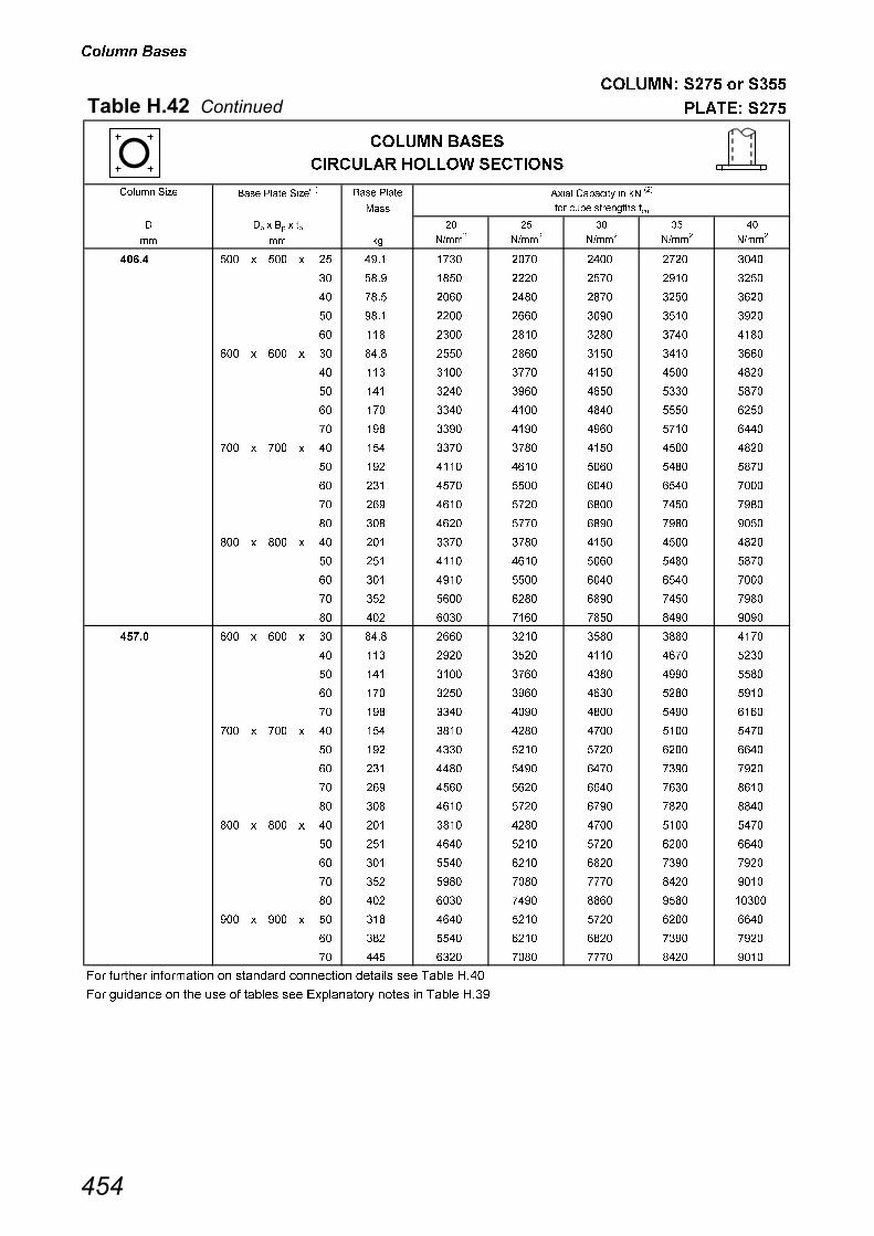
������ ��
������� �� � ���
������������������� ������ ��
���� ����� ����� ���� ����� � �� ������� � ��
���
���� ��� ���� ��������� ���
�� �� �� �� � !� ! "�
## �� �$##�
�$##�
�$##�
�$##�
�$##�
��� � ��� � ��� � �� ���� ��� ���� ���� ���� ���
��� � ��� � ��� � � ���� ���� ���� ���� ���� ���
��� � ��� � ��� � �� ���� ��� ���� ���� ��� ��
��� � ��� � ��� � �� ���� ���� �� ��� ��� ���
��� � ��� � ��� � � ��� ��� ���� ��� ��� ����
��� � �� � �� � � ���� ���� ��� ��� ��� �
��� � �� � �� � �� �� ��� ��� ���� ���� ����
��� � �� � �� � �� ��� ��� �� ��� �� ����
��� � �� � �� � � ��� �� ���� ���� ���� ���
��� � �� � �� � �� ��� �� ���� ��� ���� ���
��� � ��� � ��� � �� ��� �� ��� ���� ���� ����
�� ��� ���� ��� ��� ���� ����
��� � � �� ���� ���� ��� ��� ����
��� � ��� � ��� � �� �� ��� ���� ��� ���� ����
��� � ��� � ��� � �� �� ��� ���� ��� ���� ����
��� � ��� � ��� � �� ��� �� ��� ���� ���� ����
��� � ��� � ��� � �� ��� ���� ��� ��� ���� ����
��� � ��� � ��� � � �� ���� ���� ��� ��� ����
��� � ��� � ��� � �� �� ��� ��� ��� ���� ����
��� � ��� � ��� � �� ��� �� ��� ���� ���� ����
��� � �� � �� � � ���� �� ��� ��� ��� ����
��� � �� � �� � �� �� ���� ��� ���� ��� ���
��� � �� � �� � �� ��� ��� �� ��� ���� ����
��� � �� � �� � � ��� ��� �� �� ���� ����
��� � �� � �� � �� ��� �� ���� ���� ���� ��
��� � ��� � ��� � �� ��� ��� ���� ���� ���� ����
��� � ��� � ��� � �� ��� �� ���� ���� ��� ��
��� � ��� � ��� � � �� ���� ���� ��� ��� ����
��� � ��� � ��� � �� �� ��� ��� �� �� ���
��� � ��� � ��� � �� �� ��� ���� ��� ���� ����
��� � ��� � ��� � �� ��� ��� ���� ���� ���� ����
��� � ��� � ��� � �� ��� ��� ���� ���� ��� ��
��� � ��� � ��� � � �� ���� ��� ��� ��� ����
��� � ��� � ��� � �� �� ���� ���� ���� ���� ����
��� � ��� � ��� � �� ��� �� ���� ��� ���� ����
��� � ��� � ��� � �� �� ��� ���� ���� ��� ��
��� � ��� � ��� � � �� ���� ��� ��� ��� ����
��� � ��� � ��� � �� ��� �� ���� ���� ���� ����
��� ������ ����� ��� �� �� �� �� �������� �� �� � � �� ����
��� ��� �� �� �� �� �� � ��� � ���� � ���� ���� � � �� ����
����#� ��
�
##
������ ���
�������� ������ ������
���

������ ��
������� �� � ���
������������������� ������ ��
���� ����� ����� ���� ����� � �� ������� � ��
���
���� ��� ���� ��������� ���
�� �� �� �� � !� ! "�
## �� �$##�
�$##�
�$##�
�$##�
�$##�
���� � ��� � ��� � �� ��� ��� ��� ���� ��� ���
���� � ��� � ��� � �� ��� ���� ���� ��� �� ����
���� � ��� � ��� � � �� ��� ���� ��� ���� ����
���� � ��� � ��� � �� �� ���� ���� ��� ��� ����
���� � ��� � ��� � �� �� ���� ��� �� ���� ����
���� � ��� � ��� � �� ��� ���� ��� ���� ��� ���
���� � ��� � ��� � �� ��� ���� ���� �� ��� ����
���� � ��� � ��� � � �� ���� ��� ��� ��� ����
���� � ��� � ��� � �� �� ���� ���� ���� ��� �����
���� � ��� � ��� � �� ��� ���� ��� ���� ����� ����
���� � ��� � ��� � �� ��� ��� ��� ��� ����� �����
���� � ��� � ��� � � �� ��� ��� ��� ��� ����
���� � ��� � ��� � �� ��� ���� ���� �� ��� �����
���� � ��� � ��� � �� ��� ���� ���� ��� ����� �����
���� � ��� � ��� � �� ��� ��� ���� ����� ����� ����
���� � ��� � ��� � ��� �� ��� ����� ���� ����
��� ������ ����� ��� �� �� �� �� �������� �� �� � � �� ����
��� ��� �� �� �� �� �� � ��� � ���� � ���� ���� � � �� ����
����#� ��
�
##
������ ���
�������� ������ ������
���

������ ��
������� �� � ���
�������� ������ ��
���� ����� ����� ���� ��� ������� � ��
���
��� ���� ��������� ���
�� �� � � !�
�� �"##�
�"##�
�"##�
�"##�
�"##�
��� � ��� � ��� � ��� � �� ���� ��� � �� �� �
��� � ��� � ��� � ��� � �� ���� �� �� ���� ����
��� � ��� � ��� � ��� � �� ���� � ���� ���� ���� ����
��� � ��� � ��� � ��� � �� ���� ��� ���� ���� ���� ����
��� � ��� � ��� � ��� � �� ��� �� �� ���� ����
��� � ��� � ��� � ��� � �� ���� � ���� ���� ���� ����
��� � ��� � ��� � ��� � �� �� ���� ���� ���� ���� ����
��� � ��� � ��� � ��� � �� ���� ��� ���� ��� ��� ���
��� � ��� � ��� � ��� � �� ���� �� �� ���� ����
��� � ��� � ��� � ��� � �� ���� � ���� ���� ���� ����
��� � ��� � ��� � ��� � �� ���� ���� ���� ���� ���� ����
��� � ��� � ��� � ��� � �� ���� ��� ���� ��� ��� ���
��� � ��� � ��� � ��� � �� ���� ���� ��� ��� ���� ����
��� � ��� � ��� � ��� � �� ��� � ���� ���� ���� ����
��� � ��� � ��� � ��� � �� ���� ���� ���� ���� ���� ����
��� � ��� � ��� � ��� � �� ���� ��� ���� ��� ��� ���
��� � ��� � ��� � ��� � �� ���� ���� ��� ��� ���� ����
��� � ��� � ��� � ��� � �� ���� ��� �� ���� ���� ����
��� � ��� � ��� � ��� � �� ���� ��� ��� �� � ��
��� � ��� � ��� � ��� � �� ���� �� � ���� ���� ����
��� � ��� � ��� � ��� � �� ���� ���� ���� ��� ���� ����
��� � ��� � ��� � ��� � �� ���� ��� ���� ���� ���� ���
��� � ��� � ��� � ��� � �� ��� �� � ���� ���� ����
��� � ��� � ��� � ��� � �� ���� ���� ���� ��� ���� ����
��� � ��� � ��� � ��� � �� �� ���� ���� ���� ���� ���
��� � ��� � ��� � ��� � �� ���� ���� ���� ��� ��� ����
��� � ��� � ��� � ��� � �� ���� �� � ���� ���� ����
��� � ��� � ��� � ��� � �� ���� ���� ���� ��� ���� ����
��� � ��� � ��� � ��� � �� ���� ���� ���� ���� ���� ���
��� � ��� � ��� � ��� � �� ���� ���� ���� ��� ��� ����
��� � ��� � ��� � ��� � �� ���� ���� �� ���� ���� ����
��� � ��� � ��� � ��� � �� ��� ���� ���� ��� ���� ����
��� � ��� � ��� � ��� � �� ���� ���� ���� ���� ���� ���
��� � ��� � ��� � ��� � �� ���� ���� ���� ��� ��� ����
��� � ��� � ��� � ��� � �� ���� ���� �� ���� ���� ����
��� � ��� � ��� � ��� � �� ���� ��� ���� ��� ���� ����
��� ������ ����� ��� �� �� �� �� �������� �� �� � � �� ����
��� ��� �� �� �� �� �� � ��� � ���� � ���� ���� � � �� ����
##
$� � �� � ��
##
������ ���
����� ������ ������
����#� ��
$ � �
���

������ ��
������� �� � ���
������������������� ������ ��
���� ����� ����� ���� ��� ������� � ��
���
��� ���� ��������� ���
�� �� � � !�
�� �"##�
�"##�
�"##�
�"##�
�"##�
��� � ��� � ��� � ��� � �� ��� �� ��� ��� ��� ���
��� � ��� � ��� � ��� � �� ���� ��� ���� ���� ��� ����
��� � ��� � ��� � ��� � �� �� ���� ��� ���� �� ����
��� � ��� � ��� � ��� � �� ���� ���� ��� ���� ��� ����
��� � ��� � ��� � ��� � �� ���� �� ��� ��� ��� ���
��� � ��� � ��� � ��� � �� ���� ��� ���� ���� ��� ����
��� � ��� � ��� � ��� � �� ���� ���� ��� ���� �� ����
��� � ��� � ��� � ��� � �� ���� ���� ��� ���� ��� ����
��� � ��� � ��� � ��� � �� ���� �� ���� ���� ��� ����
��� � ��� � ��� � ��� � �� ��� ��� ���� ���� ��� ����
��� � ��� � ��� � ��� � �� ���� ���� ��� ���� �� ����
��� � ��� � ��� � ��� � �� ���� ���� ��� ���� ��� ����
��� � ��� � ��� � ��� � �� ���� �� ���� ���� ��� ����
��� � ��� � ��� � ��� � �� ���� ���� ���� ���� ���� ���
��� � ��� � ��� � ��� � �� ��� ��� ���� ���� ��� ����
��� � ��� � ��� � ��� � �� �� ���� ��� ���� �� ����
��� � ��� � ��� � ��� � �� ��� �� ���� ���� ��� ����
��� � ��� � ��� � ��� � �� �� ��� ���� ��� ���� ����
��� � ��� � ��� � ��� � �� �� �� ���� ���� ���� ���
��� � ��� � ��� � ��� � �� ���� ���� ��� ���� ���� ����
��� � ��� � ��� � ��� � �� ���� ���� ��� ���� ���� ��
��� � ��� � ��� � ��� � �� ���� ���� ���� ��� ���� ����
��� � ��� � ��� � ��� � �� ���� ��� ���� ���� ���� ����
��� � ��� � ��� � ��� � �� ���� ��� ���� ���� ���� ���
��� � ��� � ��� � ��� � �� ��� ���� ��� ���� ���� ��
��� � ��� � ��� � ��� � �� ���� ���� ���� ��� ���� ����
��� � ��� � ��� � ��� � �� ���� ��� ���� ���� ���� ����
��� � ��� � ��� � ��� � �� ���� ��� ���� ���� ���� ���
��� � ��� � ��� � ��� � �� ���� ���� ���� ��� ���� ����
��� � ��� � ��� � ��� � �� ��� ���� ��� ���� ���� ��
��� � ��� � ��� � ��� � �� �� ���� ���� ��� ���� ����
��� � ��� � ��� � ��� � �� ��� ��� ���� ���� ���� ���
��� � ��� � ��� � ��� � �� �� ���� �� ���� ��� ����
��� � ��� � ��� � ��� � �� �� ���� ���� ��� ��� ����
��� ������ ����� ��� �� �� �� �� �������� �� �� � � �� ����
��� ��� �� �� �� �� �� � ��� � ���� � ���� ���� � � �� ����
##
$� � �� � ��
##
������ ���
����� ������ ������
����#� ��
$ � �
���

������ ��
������� �� � ���
������������������� ������ ��
���� ����� ����� ���� ��� ������� � ��
���
��� ���� ��������� ���
�� �� � � !�
�� �"##�
�"##�
�"##�
�"##�
�"##�
��� � ��� � ��� � ��� � �� ��� ���� ��� ���� ���� ���
��� � ��� � ��� � ��� � �� ���� �� ���� ���� ���� ���
��� � ��� � ��� � ��� � �� ���� ���� ��� ��� ���� ���
��� � ��� � ��� � ��� � �� ���� ���� ��� ���� ��� ����
��� � ��� � ��� � ��� � �� ���� ���� ���� ���� ��� ����
��� � ��� � ��� � ��� � �� ��� ���� ��� ���� ���� ���
��� � ��� � ��� � ��� � �� �� �� ���� ���� ���� ���
��� � ��� � ��� � ��� � �� ��� ���� ��� ���� ��� ����
��� � ��� � ��� � ��� � �� �� ���� ���� ��� ���� ����
��� � ��� � ��� � ��� � �� �� ���� ���� ���� ���� ����
��� � ��� � ��� � ��� � �� �� �� ���� ���� ���� ���
��� � ��� � ��� � ��� � �� ��� ���� ��� ���� ��� ����
��� � ��� � ��� � ��� � �� ��� ���� ���� ��� ���� ����
��� � ��� � ��� � ��� � �� ��� �� ���� ���� ���� ����
��� � ��� � ��� � ��� � �� � ���� �� ���� ��� ����
��� � ��� � ��� � ��� � �� ��� ���� ���� ��� ��� ��
��� � ��� � ��� � ��� � �� �� ��� ��� ��� ��� ����
��� � ��� � ��� � ��� � �� ��� ��� ���� �� ���� ����
��� � ��� � ��� � ��� � �� �� �� ���� ���� ��� ���
��� � ��� � ��� � ��� � �� �� ���� ���� ��� ���� ���
��� � ��� � ��� � ��� � �� �� ��� ��� ��� ��� ����
��� � ��� � ��� � ��� � �� ��� ���� ���� �� ���� ����
��� � ��� � ��� � ��� � �� ��� ��� ���� ���� ���� ���
��� � ��� � ��� � ��� � �� ��� ���� ���� ���� ���� ����
��� � ��� � ��� � ��� � �� ��� ���� ���� �� ���� ����
��� � ��� � ��� � ��� � �� �� ��� ���� ���� ���� ���
��� � ��� � ��� � ��� � �� ��� ���� ���� ���� ���� ����
��� � ��� � ��� � ��� � �� �� ���� �� ���� ��� ����
��� � ��� � ��� � ��� � � �� �� ��� ��� ��� ���
��� � ��� � ��� � ��� � �� ��� ���� ���� ��� ��� ����
��� � ��� � ��� � ��� � �� �� ���� ���� ���� ���� ����
��� � ��� � ��� � ��� � �� ��� ��� ���� ���� ���� ����
��� � ��� � ��� � ��� � �� �� ��� ���� ���� �� ���
��� � ��� � ��� � ��� � �� �� ��� ���� ���� ���� ����
��� � ��� � ��� � ��� � �� ��� ��� ���� ���� ��� ����
��� � ��� ��� � ��� � �� ��� ���� ���� ���� ���� ����
��� � ��� ��� � ��� � �� ��� ���� ���� ��� ���� ���
��� � ��� ��� � ��� � �� � ���� ���� ���� ��� ���
��� � ��� ��� � ��� � �� ��� ��� ���� ���� ��� ����
��� � ��� ��� � ��� � �� �� ���� ���� ���� ���� ����
��� � ��� ��� � ��� � �� ��� ���� ���� ���� ���� ���
��� � ��� ��� � ��� � �� �� �� ��� ���� ��� ���
��� � ��� ��� � ��� � � �� �� ���� �� �� ��
��� ������ ����� ��� �� �� �� �� �������� �� �� � � �� ����
��� ��� �� �� �� �� �� � ��� � ���� � ���� ���� � � �� ����
##
$� � �� � ��
##
������ ���
����� ������ ������
����#� ��
$ � �
���

������ ��
������� �� � ���
������������������� ������ ��
���� ����� ����� ���� ��� ������� � ��
���
��� ���� ��������� ���
�� �� � � !�
�� �"##�
�"##�
�"##�
�"##�
�"##�
�� � �� ��� � ��� � �� �� ���� ���� ���� ���� ���
�� � �� ��� � ��� � �� ��� ���� ��� ���� ���� ����
�� � �� ��� � ��� � �� ��� ���� ���� ���� �� ����
�� � �� ��� � ��� � �� ��� ��� ���� ���� ���� ���
�� � �� ��� � ��� � �� � ���� ���� ���� ���� ��
�� � �� ��� � ��� � �� ��� ���� ��� ���� ���� ����
�� � �� ��� � ��� � �� �� ���� ��� ��� ��� ����
�� � �� ��� � ��� � �� ��� ��� ��� ���� ��� ��
�� � �� ��� � ��� � �� �� �� ���� ��� ��� �����
�� � �� ��� � ��� � � �� �� ���� �� ����� �����
�� � �� �� � �� � �� ��� ���� ��� ���� ���� ����
�� � �� �� � �� � �� ��� ���� ��� ��� ��� ����
�� � �� �� � �� � �� ��� ���� ��� ���� ��� ��
�� � �� �� � �� � �� ��� ���� �� ��� ��� �����
�� � �� �� � �� � � ��� ��� �� �� ����� �����
�� � �� �� � �� � � ��� ��� ��� ���� ����� �����
�� � �� ��� � ��� � �� �� ��� ���� ���� ��� ����
�� � �� ��� � ��� � �� ��� ��� ��� ���� ���� ���
�� � �� ��� � ��� � �� ��� ���� ��� ���� ���� ���
�� � �� ��� � ��� � �� ��� ��� ���� �� ��� ���
�� � �� ��� � ��� � �� � ��� ���� ��� ��� ���
�� � �� ��� � ��� � �� ��� ��� ���� ��� ��� ���
�� � �� ��� � ��� � �� �� ���� ���� ���� ��� ���
�� � �� ��� � ��� � �� ��� ���� ���� ��� ��� �����
�� � �� ��� � ��� � �� �� ��� ���� ��� �� �����
�� � �� ��� � ��� � � �� �� ���� �� ����� �����
�� � �� �� � �� � �� ��� ��� ���� ��� ��� ���
�� � �� �� � �� � �� ��� ��� ���� ���� ��� ���
�� � �� �� � �� � �� ��� ��� ��� ��� ��� �����
�� � �� �� � �� � �� ��� ���� �� �� ����� �����
�� � �� �� � �� � � ��� ��� ��� ����� ����� ����
�� � �� �� � �� � � ��� ��� ��� ����� ����� �����
�� � �� �� � �� � �� ��� ��� �� �� ����� �����
�� � �� �� � �� � � �� ��� ����� ����� ����� ����
�� � �� �� � �� � � ��� ��� ����� ����� ����� �����
�� � �� �� � �� � ��� ��� ��� ����� ����� ����� �����
��� ������ ����� ��� �� �� �� �� �������� �� �� � � �� ����
��� ��� �� �� �� �� �� � ��� � ���� � ���� ���� � � �� ����
##
$� � �� � ��
##
������ ���
����� ������ ������
����#� ��
$ � �
���

������ ��
������� �� � ���
������������������� ������ ��
���� ����� ����� ���� ��� ������� � ��
���
��� ���� ��������� ���
�� �� � � !�
�� �"##�
�"##�
�"##�
�"##�
�"##�
��� � ��� ��� � ��� � �� ��� ��� ���� ���� ���� ����
��� � ��� ��� � ��� � �� �� ���� ���� ���� ��� ��
��� � ��� ��� � ��� � �� ��� ��� ��� �� ��� �����
��� � ��� ��� � ��� � �� �� ���� ���� ��� ��� �����
��� � ��� ��� � ��� � � �� ��� ��� �� ��� �����
��� � ��� �� � �� � �� ��� ���� ���� ���� ���� ����
��� � ��� �� � �� � �� ��� ���� ���� ��� ��� ��
��� � ��� �� � �� � �� ��� ��� ��� �� ����� �����
��� � ��� �� � �� � �� ��� ���� ��� ���� ���� �����
��� � ��� �� � �� � � ��� ���� ��� ����� ���� �����
��� � ��� �� � �� � � ��� ��� ��� ����� ����� ����
��� � ��� �� � �� � �� ��� �� �� ���� ���� �����
��� � ��� �� � �� � � �� �� ����� ����� ����� �����
��� � ��� �� � �� � � ��� ��� ����� ����� ����� ����
��� � ��� �� � �� � ��� ��� ��� ����� ����� ����� �����
��� � ��� ���� � ���� � �� �� ���� ���� ��� ��� ��
��� � ��� ���� � ���� � �� ��� ���� ��� �� ����� �����
��� � ��� ���� � ���� � �� ��� �� �� ���� ���� �����
��� � ��� ���� � ���� � � �� ����� ����� ����� ����� �����
��� � ��� ���� � ���� � � ��� ����� ����� ����� ����� ����
��� � ��� ���� � ���� � ��� �� ����� ����� ����� ����� �����
��� � ��� ���� � ���� � ��� �� ����� ���� ����� ����� ���
��� � ��� ���� � ���� � ��� �� ����� ����� ����� ���� �����
��� ������ ����� ��� �� �� �� �� �������� �� �� � � �� ����
��� ��� �� �� �� �� �� � ��� � ���� � ���� ���� � � �� ����
##
$� � �� � ��
##
������ ���
����� ������ ������
����#� ��
$ � �
���
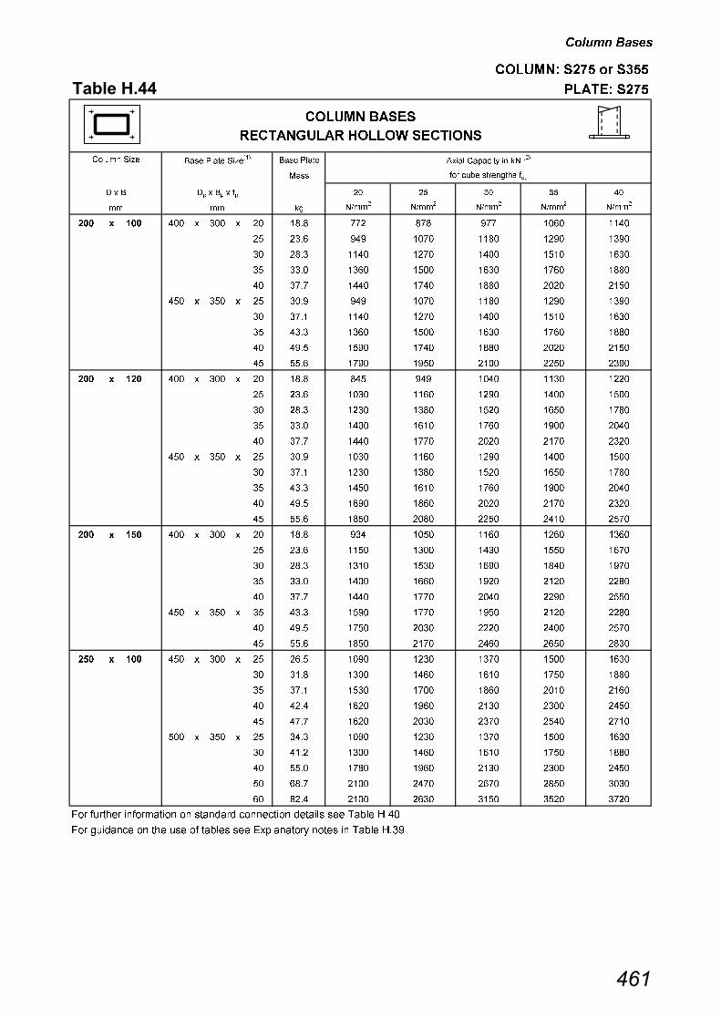
������ ��
������� �� � ���
�������� ������ ��
���� ����� ����� ���� ����� � �� ������� � ��
���
���� ��� ���� ��������� ���
�� �� � � !�
�� �"##�
�"##�
�"##�
�"##�
�"##�
��� � ��� � ��� � ��� � �� ��� � �� � ���� ����
��� � ��� � ��� � ��� � �� ��� ��� ��� ���� ���� ����
��� � ��� � ��� � ��� � �� ��� ���� ��� ���� ���� ����
��� � ��� � ��� � ��� � �� ��� ���� ���� ���� ��� ����
��� � ��� � ��� � ��� � �� � ���� ��� ���� ���� ����
��� � ��� � ��� � ��� � �� ��� ��� ��� ���� ���� ����
��� � ��� � ��� � ��� � �� �� ���� ��� ���� ���� ����
��� � ��� � ��� � ��� � �� ��� ���� ���� ���� ��� ����
��� � ��� � ��� � ��� � �� ��� ���� ��� ���� ���� ����
��� � ��� � ��� � ��� � �� ��� ��� ���� ���� ���� ����
��� � ��� � ��� � ��� � �� ��� ��� ��� ���� ���� ����
��� � ��� � ��� � ��� � �� ��� ���� ���� ���� ���� ����
��� � ��� � ��� � ��� � �� ��� ���� ���� ���� ���� ���
��� � ��� � ��� � ��� � �� ��� ���� ���� ��� ���� ����
��� � ��� � ��� � ��� � �� � ���� �� ���� ��� ����
��� � ��� � ��� � ��� � �� ��� ���� ���� ���� ���� ����
��� � ��� � ��� � ��� � �� �� ���� ���� ���� ���� ���
��� � ��� � ��� � ��� � �� ��� ���� ���� ��� ���� ����
��� � ��� � ��� � ��� � �� ��� ���� ���� ���� ��� ����
��� � ��� � ��� � ��� � �� ��� ���� ���� ���� ���� ���
��� � ��� � ��� � ��� � �� ��� ��� ���� ���� ���� ����
��� � ��� � ��� � ��� � �� ��� ���� ���� ���� ���� ���
��� � ��� � ��� � ��� � �� ��� ���� ���� ���� ���� ���
��� � ��� � ��� � ��� � �� ��� ���� ���� ���� ���� ����
��� � ��� � ��� � ��� � �� � ���� �� ���� ���� ����
��� � ��� � ��� � ��� � �� ��� ���� �� ���� ���� ����
��� � ��� � ��� � ��� � �� ��� ��� ���� ���� ���� ���
��� � ��� � ��� � ��� � �� ��� ���� ��� ���� ���� ����
��� � ��� � ��� � ��� � �� ��� ���� ���� ��� ���� ����
��� � ��� � ��� � ��� � �� ��� ���� ���� ���� ��� ����
��� � ��� � ��� � ��� � �� �� ���� ��� ���� ���� ����
��� � ��� � ��� � ��� � �� ��� ���� ���� ���� ���� ����
��� � ��� � ��� � ��� � �� � ���� ���� ��� ���� ���
��� � ��� � ��� � ��� � �� ��� ���� ���� ��� ���� ����
��� � ��� � ��� � ��� � �� ��� ���� ���� ���� ��� ����
��� � ��� � ��� � ��� � �� ��� ��� ���� ���� ���� ����
��� � ��� � ��� � ��� � �� �� ���� ��� ��� ���� ����
��� � ��� � ��� � ��� � �� ��� ���� ���� ���� ���� ���
��� ������ ����� ��� �� �� �� �� �������� �� �� � � �� ����
��� ��� �� �� �� �� �� � ��� � ���� � ���� ���� � � �� ����
## ##
������ ���
����������� ������ ������
����#� ��
$ � $� �� ��
���

������ ��
������� �� � ���
������������������� ������ ��
���� ����� ����� ���� ����� � �� ������� � ��
���
���� ��� ���� ��������� ���
�� �� � � !�
�� �"##�
�"##�
�"##�
�"##�
�"##�
��� � ��� � ��� � ��� � �� ��� ���� ���� ���� ��� ����
��� � ��� � ��� � ��� � �� �� ���� ��� ���� ���� ����
��� � ��� � ��� � ��� � �� ��� ��� ���� ���� ���� ����
��� � ��� � ��� � ��� � �� ��� ���� ���� ���� ��� ����
��� � ��� � ��� � ��� � �� ��� ���� ���� �� ���� ����
��� � ��� � ��� � ��� � �� ��� ���� ���� ���� ��� ����
��� � ��� � ��� � ��� � �� �� ���� ��� ���� ���� ����
��� � ��� � ��� � ��� � �� ��� ���� ���� ���� ��� ����
��� � ��� � ��� � ��� � �� �� ���� ���� ���� ���� ����
��� � ��� � ��� � ��� � �� ��� ���� ���� ���� ���� ����
��� � ��� � ��� � ��� � �� � ���� ��� ���� ���� ����
��� � ��� � ��� � ��� � �� ��� ���� ���� ���� ��� ����
��� � ��� � ��� � ��� � �� ��� ���� ���� ���� ���� ����
��� � ��� � ��� � ��� � �� ��� ���� ���� ��� ���� ����
��� � ��� � ��� � ��� � �� ��� ���� ���� ���� ��� ����
��� � ��� � ��� � ��� � �� ��� ���� ���� ���� ���� ����
��� � ��� � ��� � ��� � �� �� ���� ���� ���� ��� ���
��� � ��� � ��� � ��� � �� ��� ���� ���� ��� ���� ����
��� � ��� � ��� � ��� � �� � ���� ���� ��� ���� ����
��� � ��� � ��� � ��� � �� ��� ���� ���� ���� ���� ����
��� � ��� � ��� � ��� � �� �� ��� ���� ���� ��� ���
��� � ��� � ��� � ��� � �� ��� ���� ��� ���� ��� ����
��� � ��� � ��� � ��� � �� ��� ���� ���� ���� ���� ����
��� � ��� � ��� � ��� � � ��� ���� ���� ���� ���� ����
��� � ��� � ��� � ��� � �� ��� ���� ��� ���� ���� ����
��� � ��� � ��� � ��� � �� �� ���� ���� ���� ���� ����
��� � ��� � ��� � ��� � �� ��� ���� ���� ���� ���� ���
��� � ��� � ��� � ��� � �� �� ���� ���� ���� ���� ����
��� � ��� � ��� � ��� � �� ��� ���� ���� ���� ���� ����
��� � ��� � ��� � ��� � �� � ���� ���� ���� ���� ����
��� � ��� � ��� � ��� � �� ��� ���� ���� ���� ���� ���
��� � ��� � ��� � ��� � �� ��� ��� ���� ���� ���� ����
��� � ��� � ��� � ��� � �� ��� ���� ��� ���� ���� ���
��� � ��� � ��� � ��� � � ��� ���� ���� ���� ��� ����
��� � ��� � �� � ��� � �� ��� ���� ���� ���� ���� ���
��� � ��� � �� � ��� � �� ��� ��� ���� ���� ���� ����
��� � ��� � �� � ��� � �� ��� ���� ��� ���� ���� ���
��� � ��� � �� � ��� � � ��� ���� ���� ���� ��� ����
��� ������ ����� ��� �� �� �� �� �������� �� �� � � �� ����
��� ��� �� �� �� �� �� � ��� � ���� � ���� ���� � � �� ����
## ##
������ ���
����������� ������ ������
����#� ��
$ � $� �� ��
���
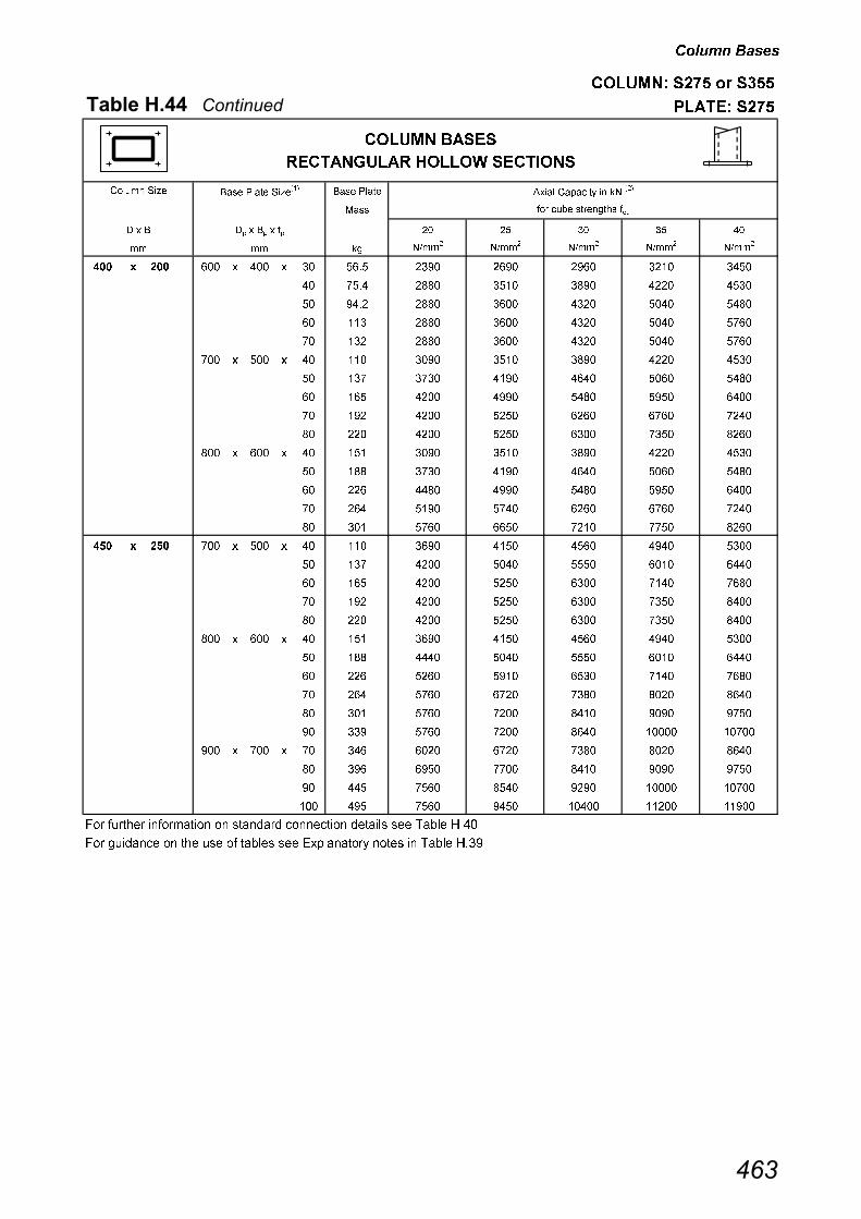
������ ��
������� �� � ���
������������������� ������ ��
���� ����� ����� ���� ����� � �� ������� � ��
���
���� ��� ���� ��������� ���
�� �� � � !�
�� �"##�
�"##�
�"##�
�"##�
�"##�
��� � ��� � ��� � ��� � �� ��� ���� ���� ���� ���� ����
��� � ��� � ��� � ��� � �� �� ���� ���� ���� ���� ����
��� � ��� � ��� � ��� � �� ��� ���� ���� ���� ���� ����
��� � ��� � ��� � ��� � �� ��� ���� ���� ���� ���� ���
��� � ��� � ��� � ��� � � ��� ���� ���� ���� ���� ���
��� � ��� � �� � ��� � �� ��� ���� ���� ���� ���� ����
��� � ��� � �� � ��� � �� �� ��� ���� ���� ���� ����
��� � ��� � �� � ��� � �� ��� ���� ���� ���� ���� ����
��� � ��� � �� � ��� � � ��� ���� ���� ���� ��� ���
��� � ��� � �� � ��� � �� ��� ���� ���� ���� ��� ����
��� � ��� � ��� � ��� � �� ��� ���� ���� ���� ���� ����
��� � ��� � ��� � ��� � �� ��� ��� ���� ���� ���� ����
��� � ��� � ��� � ��� � �� ��� ���� ���� ���� ���� ����
��� � ��� � ��� � ��� � � ��� ���� ��� ���� ��� ���
��� � ��� � ��� � ��� � �� ��� ��� ���� ��� �� ����
��� � ��� � �� � ��� � �� ��� ���� ���� ���� ���� ����
��� � ��� � �� � ��� � �� �� ���� ���� ���� ���� ����
��� � ��� � �� � ��� � �� ��� ���� ���� ���� ��� ���
��� � ��� � �� � ��� � � ��� ���� ���� ���� ��� ����
��� � ��� � �� � ��� � �� ��� ���� ���� ���� ��� ����
��� � ��� � ��� � ��� � �� ��� ���� ���� ���� ���� ����
��� � ��� � ��� � ��� � �� ��� ���� ���� ���� ���� ����
��� � ��� � ��� � ��� � �� ��� ���� ���� ���� ��� ���
��� � ��� � ��� � ��� � � ��� ��� ��� ��� ���� ����
��� � ��� � ��� � ��� � �� ��� ��� ��� ���� ���� ���
��� � ��� � ��� � ��� � �� ��� ��� ��� ���� ����� ����
��� � ��� � ��� � �� � � ��� ���� ��� ��� ���� ����
��� � ��� � ��� � �� � �� ��� ���� �� ���� ���� ���
��� � ��� � ��� � �� � �� ��� ��� ���� ���� ����� ����
��� � ��� � ��� � �� � ��� ��� ��� ���� ����� ����� �����
��� ������ ����� ��� �� �� �� �� �������� �� �� � � �� ����
��� ��� �� �� �� �� �� � ��� � ���� � ���� ���� � � �� ����
## ##
������ ���
����������� ������ ������
����#� ��
$ � $� �� ��
���
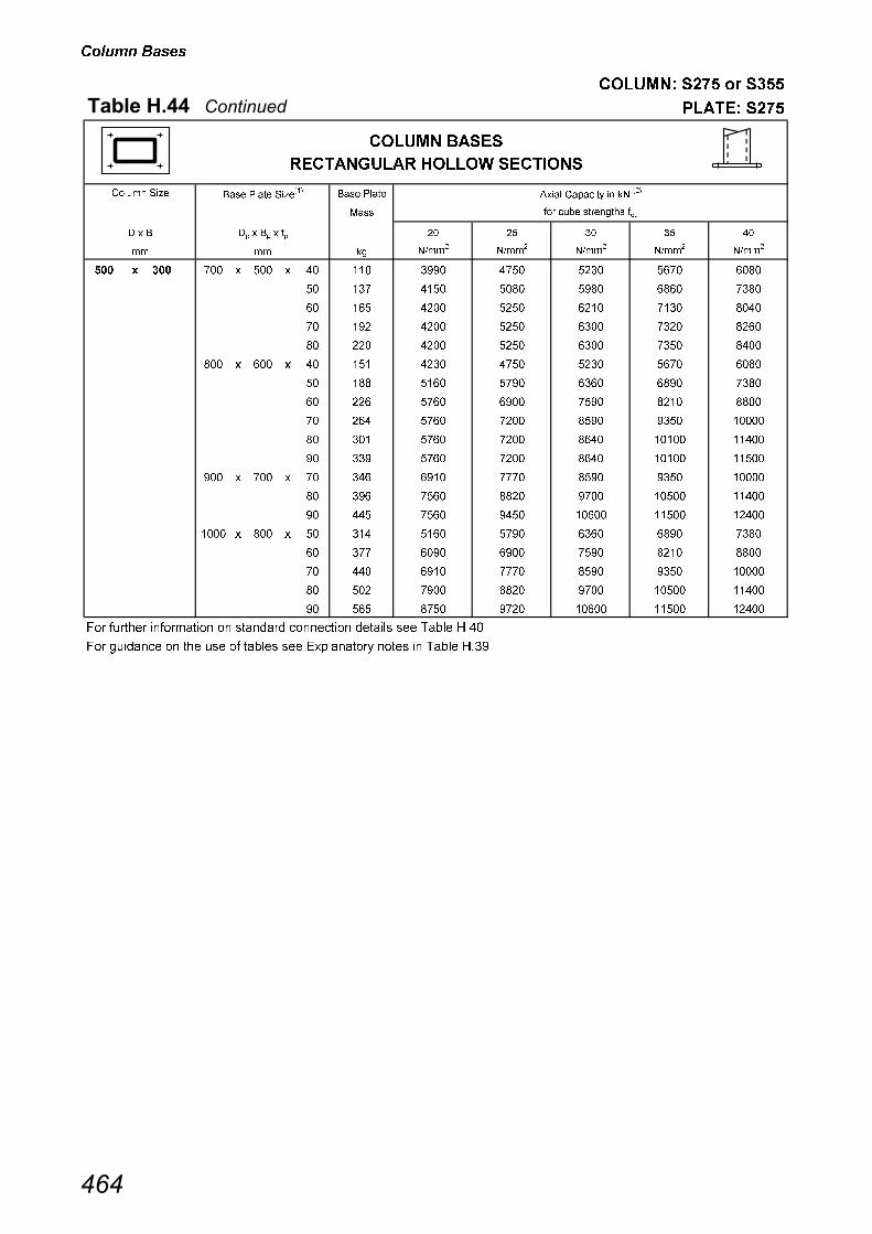
������ ��
������� �� � ���
������������������� ������ ��
���� ����� ����� ���� ����� � �� ������� � ��
���
���� ��� ���� ��������� ���
�� �� � � !�
�� �"##�
�"##�
�"##�
�"##�
�"##�
��� � ��� � �� � ��� � �� ��� ���� ��� ���� ��� ����
��� � ��� � �� � ��� � �� �� ���� ���� ���� ���� ���
��� � ��� � �� � ��� � �� ��� ���� ���� ���� ��� ����
��� � ��� � �� � ��� � � ��� ���� ���� ���� ��� ����
��� � ��� � �� � ��� � �� ��� ���� ���� ���� ��� ����
��� � ��� � ��� � ��� � �� ��� ���� ��� ���� ��� ����
��� � ��� � ��� � ��� � �� ��� ���� ��� ���� ���� ���
��� � ��� � ��� � ��� � �� ��� ��� ���� ��� ���� ����
��� � ��� � ��� � ��� � � ��� ��� ��� ���� ���� �����
��� � ��� � ��� � ��� � �� ��� ��� ��� ���� ����� �����
��� � ��� � ��� � ��� � �� ��� ��� ��� ���� ����� �����
��� � ��� � ��� � �� � � ��� ���� � ���� ���� �����
��� � ��� � ��� � �� � �� ��� ��� ���� ��� ����� �����
��� � ��� � ��� � �� � �� ��� ��� ���� ����� ����� �����
��� � ��� � ���� � ��� � �� ��� ���� ��� ���� ���� ���
��� � ��� � ���� � ��� � �� � ���� ���� ��� ���� ����
��� � ��� � ���� � ��� � � ��� ���� � ���� ���� �����
��� � ��� � ���� � ��� � �� ��� ��� ���� ��� ����� �����
��� � ��� � ���� � ��� � �� ��� ��� ��� ����� ����� �����
��� ������ ����� ��� �� �� �� �� �������� �� �� � � �� ����
��� ��� �� �� �� �� �� � ��� � ���� � ���� ���� � � �� ����
## ##
������ ���
����������� ������ ������
����#� ��
$ � $� �� ��
���
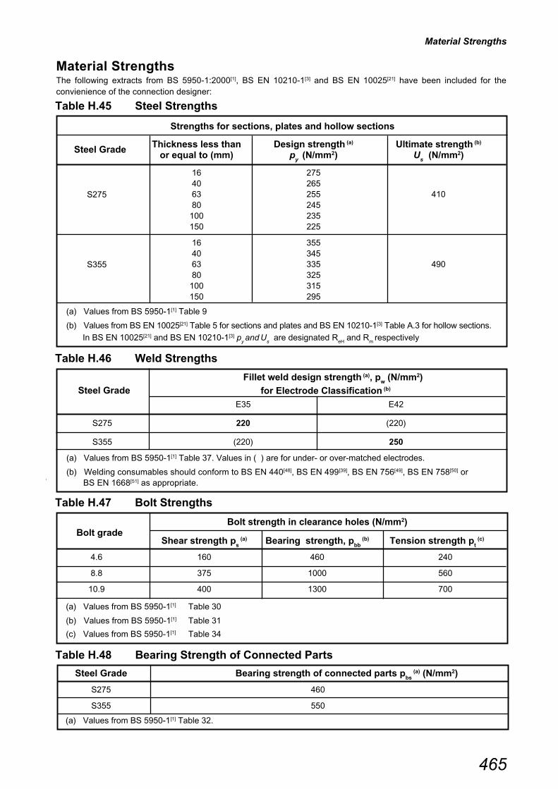
Material Strengths
465
Material StrengthsThe following extracts from BS 5950-1:2000[1], BS EN 10210-1[3] and BS EN 10025[21] have been included for theconvienience of the connection designer:
Strengths for sections, plates and hollow sections
Table H.45 Steel Strengths
Steel Grade
Fillet weld design strength (a), pw (N/mm2)
for Electrode Classification (b)
E35 E42
S275 220 (220)
S355 (220) 250
(a) Values from BS 5950-1[1] Table 37. Values in ( ) are for under- or over-matched electrodes.
(b) Welding consumables should conform to BS EN 440[48], BS EN 499[39], BS EN 756[49], BS EN 758[50] or BS EN 1668[51] as appropriate.
Table H.46 Weld Strengths
Steel Grade Bearing strength of connected parts pbs
(a) (N/mm2)
S275 460
S355 550
(a) Values from BS 5950-1[1] Table 32.
Steel GradeThickness less than Design strength (a) Ultimate strength (b)
or equal to (mm) py (N/mm2) U
s (N/mm2)
16 27540 26563 255 410S27580 245
100 235150 225
16 35540 34563 335 490S35580 325
100 315150 295
(a) Values from BS 5950-1[1] Table 9
(b) Values from BS EN 10025[21] Table 5 for sections and plates and BS EN 10210-1[3] Table A.3 for hollow sections.
In BS EN 10025[21] and BS EN 10210-1[3] py and
U
s are designated R
eH and R
m respectively
Bolt strength in clearance holes (N/mm2)
Bolt grade
Shear strength ps
(a) Bearing strength, pbb
(b) Tension strength pt
(c)
4.6 160 460 240
8.8 375 1000 560
10.9 400 1300 700
(a) Values from BS 5950-1[1] Table 30
(b) Values from BS 5950-1[1] Table 31
(c) Values from BS 5950-1[1] Table 34
Table H.47 Bolt Strengths
Table H.48 Bearing Strength of Connected Parts
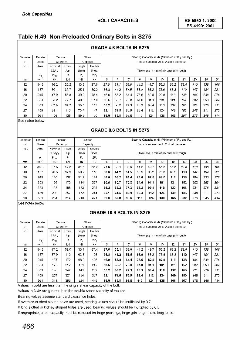
���� �������
���� �������
������������ ��������������� ����������� �����
�������� �����
� ����
���� ���� ������ ����� ����� ������
������� ���� ����� �����
�� ���� �� �� ���
�� ���
�� �� �� �� ! " � # $� $� $ �� � %�
�� ���� ���� ���� ��� ��� ���� ���� ���� ���� ��� �� ���� ���� ��� ��� ���
�� � ���� �� ��� ��� ���� ���� �� �� ���� ���� ���� ��� ��� ��� ���
�� �� ��� ��� ���� ��� ���� �� ���� ��� ���� ��� ��� ��� ��� ��� ���
�� ��� ��� �� ��� ��� ��� ��� ��� ���� ���� ��� ��� �� ��� �� ���
�� �� ��� ��� �� ��� ���� ���� �� ���� ���� ��� ��� ��� ��� ��� ���
� �� ���� ��� ��� �� ���� �� ���� ���� ��� ��� �� ��� ��� ��� ���
�� �� ��� �� ���� ��� ���� ���� ���� ��� ��� ��� ��� ��� ��� �� ���
��� ����� ���
�������� �����
� ����
���� ���� ������ ����� ����� ������
������� ���� ����� �����
�� ���� �� �� ���
�� ���
�� �� �� �� ! " � # $� $� $ �� � %�
�� ���� ��� ��� ���� ���� ��� ���� ���� ���� ��� �� ���� ���� ��� ��� ���
�� � ��� ��� ��� ��� ��� ���� ���� ��� ���� ��� ���� ��� ��� ��� ���
�� �� ��� �� ���� ��� ���� ���� ���� �� ���� ���� ��� ��� ��� ��� ���
�� ��� ��� �� ��� �� ���� ��� ��� ���� ���� ��� ��� �� ��� �� ���
�� �� �� ��� ��� �� ���� ���� � ��� ���� ��� ��� ��� ��� ��� ���
� �� ��� � �� ��� ���� ��� ���� ���� ��� ��� ��� ��� ��� ��� ���
�� �� �� ��� ��� ��� ���� ���� ���� ��� ��� �� ��� �� �� �� ���
��� ����� ���
�������� �����
� ����
���� ���� ������ ����� ����� ������
������� ���� ����� �����
�� ���� �� �� ���
�� ���
�� �� �� �� ! " � # $� $� $ �� � %�
�� ���� ��� ��� ��� ��� ��� �� ���� ���� ��� �� ���� ���� ��� ��� ���
�� � ��� ��� ���� ��� ��� ���� ���� ���� ���� ��� ���� ��� ��� ��� ���
�� �� �� �� ���� ��� ���� ���� ���� �� ���� ���� ��� ��� ��� ��� ���
�� ��� �� ��� ��� ��� ���� ��� ��� ���� ���� ��� ��� �� ��� �� ���
�� �� ��� �� ��� ��� ���� ���� � ��� ���� ��� �� ��� ��� �� ���
� �� � ��� ��� �� ���� ��� ���� ���� ��� ��� ��� ��� ��� ��� ���
�� �� ��� ��� ��� ��� ���� ���� ���� ��� ��� �� ��� �� �� �� ���
�� �� �� ���� ��� ��� ���� ��� ����� ����� �������� �� ��� ����
�� �� �� ������ ��� ������� ���� ��� �� �� ����� �������� �� ��� ����
������� �� �� ��� �� �������� �������� �����
�� �������� �� ����� ������ ���� ��� ���� ������� �� �� ��� � �� � ������ �� ����
�� ��� ������ �� ����� ������ ���� ��� ���� ������� �� �� ��� � �� � ������ �� ��!�
�� ������������ ����� �������� � �� �� ��� ��� ��� ���� ��� ����� ���� ���� ������ ��� ��� "������
������ � �� � ��' ���( ��������
� �� ���� ����� � ����
���� ����� ������ )������' � �� *+����� � ��� �( ���,
)������' )������' �( (����� �-��� �� � � ���� (��������
�( (����� �-��� �� � � ���� (��������
������ � �� � ��' ���( ��������
������ � �� � ��' ���( ��������
� �� ��� ����� � ����
���� ����� ������ )������' � �� *+����� � ��� �( ���,
)������' )������'
�� ������ ���
)������' )������'
� �� ��� ����� � ����
���� ����� ������ )������' � �� *+����� � ��� �( ���,
�( (����� �-��� �� � � ���� (��������
�� ���� ���
���
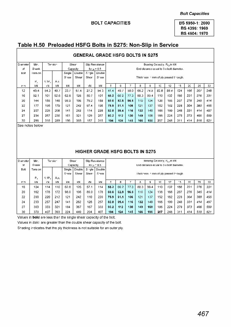
���� �������
���� �������
���������������������������������� ��������� ���� �� ����!�"�
�������� +��
� ����
���� ���� ����� ������ ����� ������
����� ����� ����� �����
��
$�$��
����
�� �� �� �� �� �� �� �� ! " � # $� $� $ �� � %�
�� ���� ��� ��� ��� ��� ��� ��� ���� ��� ��� ���� ��� ���� �� ��� ��� ��� ���
�� ���� ��� ���� ���� ��� �� ��� ���� ���� �� ���� ���� ��� ��� ��� ��� ��� ���
�� ��� �� �� ���� ��� ��� �� ���� ���� ���� ��� ��� ��� ��� ��� ��� �� ���
�� � �� �� ��� ��� ��� �� ��� ���� ��� ��� �� �� ��� ��� ��� ��� �
�� �� ��� ��� ��� ��� ��� ��� ���� ���� ��� �� ��� ��� ��� ��� ��� ��� ��
� ��� � ��� ��� ��� ��� � ��� ��� �� ��� ��� ��� ��� �� ��� ���
�� ��� �� ��� ��� ��� � �� ��� ��� ��� ��� ��� �� ��� ��� ��� �� ���
��� ����� ���
�������� +��
� ����
���� ���� ����� ������ ����� ������
����� ����� ����� �����
��
$�$��
����
�� �� �� �� �� �� �� �� ! " � # $� $� $ �� � %�
�� ��� ��� ��� ���� ��� �� ��� ���� ���� �� ���� ���� ��� ��� ��� ��� ��� ���
�� ��� �� �� ���� ��� ���� �� ���� ���� ���� ��� ��� ��� ��� ��� ��� �� ���
�� ��� ��� ��� ��� ��� ��� ��� ��� ���� ��� ��� �� �� ��� ��� ��� ��� �
�� ��� � �� ��� ��� ��� � ���� ���� ��� �� ��� ��� ��� ��� ��� ��� ��
� ��� ��� ��� ��� �� �� ��� ��� ��� �� ��� ��� ��� ��� �� ��� ���
�� �� �� ��� ��� ��� ��� �� ��� ��� ��� ��� ��� �� ��� ��� ��� �� ���
�� �� �� ���� ��� ��� ���� ��� ����� ����� �������� �� ��� ����
�� �� �� ������ ��� ������� ���� ��� �� �� ����� �������� �� ��� ����
������� ��������� ���� ��� �� ���� ���� �� ��� � ����� ��� �� � ��� ���
������ � �� � ��' ���( ��������
�� �� � �� ���� ����� � ����
)������' �� � . �� �( (����� �-��� �� % � ���� (��������
����
)������' �� � . ��
�� ������ ���
�� ���� �� �
�� � �� ����
�( (����� �-��� �� % � ���� (��������
������ )������'/ ��� � ��
���� 0������ ������ )������'/ ��� � ��
������ � �� � ��' ���( ��������
��� � �� ���� ����� � ����
���� �����
����� ���� 0������
���

���� �������
���� �������
���������#������������������������ ��������� ���� �$ ������"������%����
�������� +�� ����
� ���� ����
���� ���� )������' ����� ������ ����� ������ ����� ������ ����� ������
����� ����� ����� ����� ����� ����� ����� �����
��
��#��
�� �� �� �� �� �� �� �� �� �� ��
�� ���� ��� ���� ��� ���� ��� ��� ��� ���� ���
�� ���� ���� ���� ���� ���� ��� ���� ���� ���� ����
�� ��� ��� ��� ��� ���� �� ��� ��� ���� ���
�� � �� ���� ��� ��� ��� ��� �� �� ��
�� �� ��� ��� �� �� ��� �� ��� ���� ���
� ��� ��� ���� ���� ���� ��� ���� ��� �� ���
�� ��� � �� ��� �� �� ��� ��� ��� �
�������� +�� ����
� ���� ����
���� ���� )������' ����� ������ ����� ������ ����� ������ ����� ������
����� ����� ����� ����� ����� ����� ����� �����
��
��#��
�� �� �� �� �� �� �� �� �� �� ��
�� ��� ��� ��� ��� ���� ��� ��� ��� ���� ���
�� ��� ��� ���� ��� ��� ��� ��� ��� ��� ���
�� ��� ��� ���� ��� ��� ��� ��� ��� ���� ���
�� ��� ��� ���� ���� ���� ��� ���� ��� �� ���
� ��� �� �� ��� ���� ��� ��� ��� ��� ��
�� �� ��� ���� ��� ���� ��� ��� ��� �� ���
��� � �� ���� ����� � ����
���� 0������ ��
� . ��� � . ��% � . ��1 � . ��
���� 0������ ��
� . ��� � . ��% � . ��1 � . ��
�� ������ ���
�� ���� �� �
�� � �� ����
�� �� � �� ���� ����� � ����
���
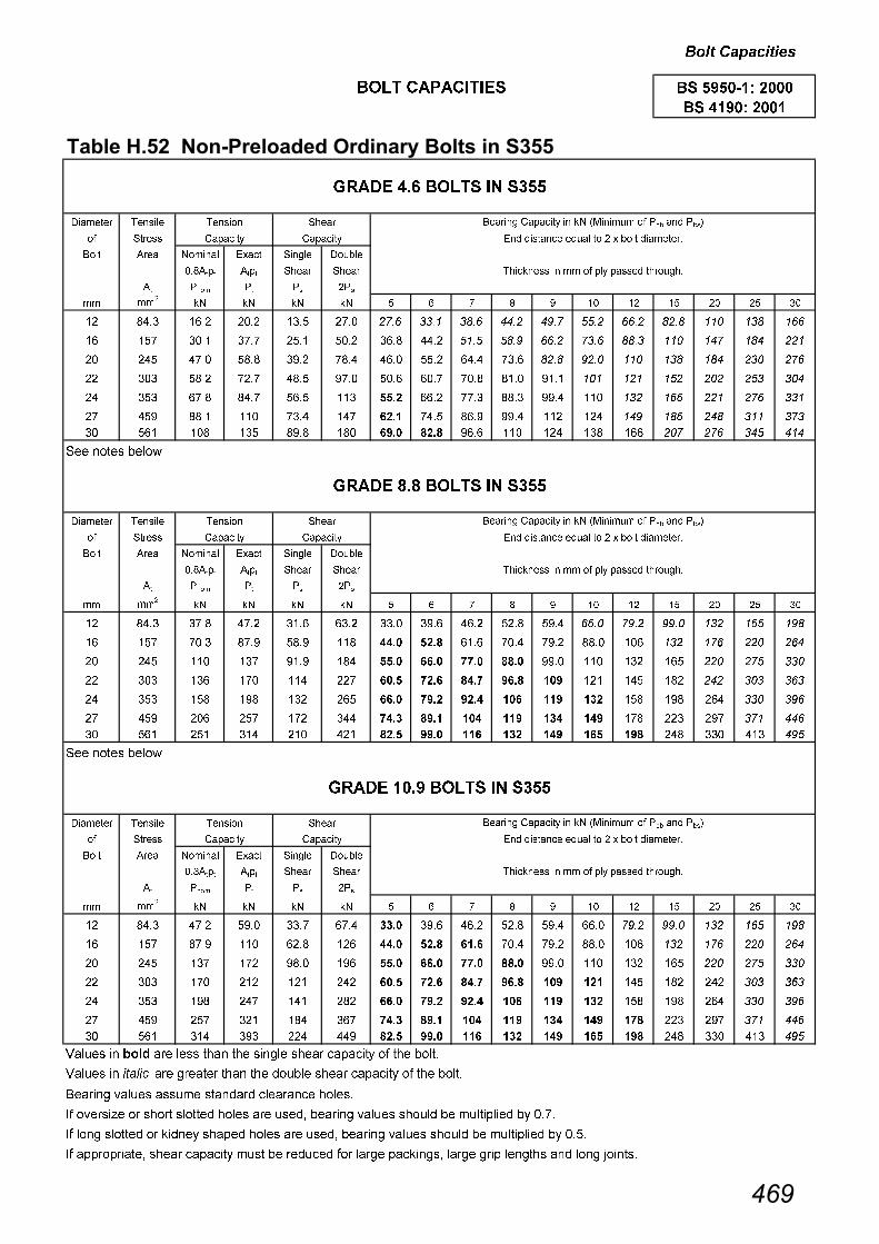
���� �������
���� �������
�������������� ��������������� ����������� ��&��
�������� �����
� ����
���� ���� ������ ����� ����� ������
������� ���� ����� �����
�� ���� �� �� ���
�� ���
�� �� �� �� ! " � # $� $� $ �� � %�
�� ���� ���� ���� ��� ��� ���� ���� ���� ���� ��� �� ���� ���� ��� ��� ���
�� � ���� �� ��� ��� ���� ���� �� �� ���� ���� ���� ��� ��� ��� ���
�� �� ��� ��� ���� ��� ���� �� ���� ��� ���� ��� ��� ��� ��� ��� ���
�� ��� ��� �� ��� ��� ��� ��� ��� ���� ���� ��� ��� �� ��� �� ���
�� �� ��� ��� �� ��� ���� ���� �� ���� ���� ��� ��� ��� ��� ��� ���
� �� ���� ��� ��� �� ���� �� ���� ���� ��� ��� �� ��� ��� ��� ���
�� �� ��� �� ���� ��� ���� ���� ���� ��� ��� ��� ��� ��� ��� �� ���
��� ����� ���
�������� �����
� ����
���� ���� ������ ����� ����� ������
������� ���� ����� �����
�� ���� �� �� ���
�� ���
�� �� �� �� ! " � # $� $� $ �� � %�
�� ���� ��� ��� ���� ���� ���� ���� ���� ��� ��� ���� ��� �� ��� �� ��
�� � ��� ��� ��� ��� ���� ���� ���� ��� ��� ���� ��� ��� ��� ��� ���
�� �� ��� �� ���� ��� ���� ���� �� ���� ���� ��� ��� �� ��� �� ���
�� ��� ��� �� ��� �� ���� ��� ��� ���� ��� ��� �� ��� ��� ��� ���
�� �� �� ��� ��� �� ���� ��� ���� ��� ��� �� �� ��� ��� ��� ��
� �� ��� � �� ��� �� ���� ��� ��� �� ��� �� ��� �� ��� ���
�� �� �� ��� ��� ��� ���� ���� ��� �� ��� ��� ��� ��� ��� ��� �
��� ����� ���
�������� �����
� ����
���� ���� ������ ����� ����� ������
������� ���� ����� �����
�� ���� �� �� ���
�� ���
�� �� �� �� ! " � # $� $� $ �� � %�
�� ���� ��� ��� ��� ��� �� ���� ���� ��� ��� ���� ��� �� ��� �� ��
�� � ��� ��� ���� ��� ���� ���� ���� ��� ��� ���� ��� ��� ��� ��� ���
�� �� �� �� ���� ��� ���� ���� �� ���� ���� ��� ��� �� ��� �� ���
�� ��� �� ��� ��� ��� ���� ��� ��� ���� ��� ��� �� ��� ��� ��� ���
�� �� ��� �� ��� ��� ���� ��� ���� ��� ��� �� �� ��� ��� ��� ��
� �� � ��� ��� �� �� ���� ��� ��� �� ��� �� ��� �� ��� ���
�� �� ��� ��� ��� ��� ���� ���� ��� �� ��� ��� ��� ��� ��� ��� �
�� �� �� ���� ��� ��� ���� ��� ����� ����� �������� �� ��� ����
�� �� �� ������ ��� ������� ���� ��� �� �� ����� �������� �� ��� ����
������� �� �� ��� �� �������� �������� �����
�� �������� �� ����� ������ ���� ��� ���� ������� �� �� ��� � �� � ������ �� ����
�� ��� ������ �� ����� ������ ���� ��� ���� ������� �� �� ��� � �� � ������ �� ��!�
�� ������������ ����� �������� � �� �� ��� ��� ��� ���� ��� ����� ���� ���� ������ ��� ��� "������
� �� ��� ����� � ����
���� ����� ������ )������' � �� *+����� � ��� �( ���,
�� ������ ���
������ � �� � ��' ���( ��������
� �� ��� ����� � ����
���� ����� ������ )������' � �� *+����� � ��� �( ���,
�� ���� ���
)������' )������' �( (����� �-��� �� � � ���� (��������
)������' )������' �( (����� �-��� �� � � ���� (��������
������ � �� � ��' ���( ��������
������ � �� � ��' ���( ��������
� �� ���� ����� � ����
���� ����� ������ )������' � �� *+����� � ��� �( ���,
)������' )������' �( (����� �-��� �� � � ���� (��������
���

���� �������
���� �������
���������&������������������������ ��&������ ���� �� ����!�"�
�������� +��
� ����
���� ���� ����� ������ ����� ������
����� ����� ����� �����
��
$�$��
����
�� �� �� �� �� �� �� �� ! " � # $� $� $ �� � %�
�� ���� ��� ��� ��� ��� ��� ��� ��� ��� ��� ��� ��� �� �� �� �� ��� ��
�� ���� ��� ���� ���� ��� �� ��� ���� ��� ���� ��� ��� ��� �� �� ��� ��� ��
�� ��� �� �� ���� ��� ��� �� ���� ���� ��� ��� ��� �� �� ��� ��� ��� �
�� � �� �� ��� ��� ��� �� ���� ��� �� �� ��� ��� ��� ��� ��� �� �
�� �� ��� ��� ��� ��� ��� ��� ���� ��� �� �� �� ��� ��� �� �� � �
� ��� � ��� ��� ��� ��� � ��� �� ��� �� ��� ��� �� ��� ��� � ���
�� ��� �� ��� ��� ��� � �� ��� ��� � ��� ��� ��� �� �� � �� ���
��� ����� ���
�������� +��
� ����
���� ���� ����� ������ ����� ������
����� ����� ����� �����
��
$�$��
����
�� �� �� �� �� �� �� �� ! " � # $� $� $ �� � %�
�� ��� ��� ��� ���� ��� �� ��� ���� ��� ���� ��� ��� ��� �� �� ��� ��� ��
�� ��� �� �� ���� ��� ���� �� ���� ���� ��� ��� ��� �� �� ��� ��� ��� �
�� ��� ��� ��� ��� ��� ��� ��� ���� ��� �� �� ��� ��� ��� ��� ��� �� �
�� ��� � �� ��� ��� ��� � ���� ��� �� �� �� ��� ��� �� �� � �
� ��� ��� ��� ��� �� �� ��� ��� �� ��� �� ��� ��� �� ��� ��� � ���
�� �� �� ��� ��� ��� ��� �� ��� ��� � ��� �� ��� �� �� � �� ���
�� �� �� ���� ��� ��� ���� ��� ����� ����� �������� �� ��� ����
�� �� �� ������ ��� ������� ���� ��� �� �� ����� �������� �� ��� ����
������� ��������� ���� ��� �� ���� ���� �� ��� � ����� ��� �� � ��� ���
�� ������ ���
�� ���� �� �
�� � �� ����
������ � �� � ��' ���( ��������
�� �� � �� ���� ����� � ����
���� ����� ���� 0������ ������ )������'/ ��� � ��
��� � �� ���� ����� � ����
)������' �� � . �� �( (����� �-��� �� % � ���� (��������
����
������ � �� � ��' ���( ��������
)������' �� � . �� �( (����� �-��� �� % � ���� (��������
����� ���� 0������ ������ )������'/ ��� � ��
���

���� �������
���� �������
�������������������������������� ��&������ ���� �$ ������"������%����
�������� +�� ����
� ���� ����
���� ���� )������' ����� ������ ����� ������ ����� ������ ����� ������
����� ����� ����� ����� ����� ����� ����� �����
��
��#��
�� �� �� �� �� �� �� �� �� �� ��
�� ���� ��� ���� ��� ���� ��� ��� ��� ���� ���
�� ���� ���� ���� ���� ���� ��� ���� ���� ���� ����
�� ��� ��� ��� ��� ���� �� ��� ��� ���� ���
�� � �� ���� ��� ��� ��� ��� �� �� ��
�� �� ��� ��� �� �� ��� �� ��� ���� ���
� ��� ��� ���� ���� ���� ��� ���� ��� �� ���
�� ��� � �� ��� �� �� ��� ��� ��� �
�������� +�� ����
� ���� ����
���� ���� )������' ����� ������ ����� ������ ����� ������ ����� ������
����� ����� ����� ����� ����� ����� ����� �����
��
��#��
�� �� �� �� �� �� �� �� �� �� ��
�� ��� ��� ��� ��� ���� ��� ��� ��� ���� ���
�� ��� ��� ���� ��� ��� ��� ��� ��� ��� ���
�� ��� ��� ���� ��� ��� ��� ��� ��� ���� ���
�� ��� ��� ���� ���� ���� ��� ���� ��� �� ���
� ��� �� �� ��� ���� ��� ��� ��� ��� ��
�� �� ��� ���� ��� ���� ��� ��� ��� �� ���
�� ���� �� �
�� ������ ���
� . ��� � . ��% � . ��1 � . ��
�� � �� ����
��� � �� ���� ����� � ����
���� 0������ ��
�� �� � �� ���� ����� � ����
���� 0������ ��
� . ��� � . ��% � . ��1 � . ��
���

Fasteners for RHS Sections
472
FLOWDRILL
Tension capacity - normal design
The tension capacity of Grade 8.8 bolts for normal design are shown in Table H.55a and take account of the RHS wallthickness as well as the bolt strength.
Table H.55a
FLOWDRILL CONNECTIONSNormal tension capacity (Pnom)kN
Bolt RHS column wall thickness mm
diameter S275 S355
mm5 6.3 8 10 12.5 5 6.3 8 to 12.5
M16 46 60 70.3 59 70.3
M20 70 85 95 97 110 102 110
M24 80 101 122 134 158 103 130 158
Tension capacity - structural integrity
The pull-out resistances for structural integrity are less than those for normal design because the design method usedfor structural integrity leads to thinner plates/cleats than for normal design methods, based on BS 5950-1:2000[1], and,as a result, will lead to higher prying forces.
The values in Table H.55b are based on limiting value of ptr= 300N/mm2 for extreme prying (See CHECK 13).
Table H.55b
FLOWDRILL CONNECTIONSStructural integrity tension capacity (Psi)kN
Bolt RHS column wall thickness mm
diameter S275 S355
mm5 6.3 8 10 12.5 5 6.3 8 to 12.5
M16 30 40 46 39 46
M20 46 56 63 65 73 68 73
M24 53 67 81 89 106 68 86 106
Shear and bearing capacity
For shear and bearing capacities, refer to capacity tables for ordinary bolts (Tables H.49 and H.52)
Note: Additional information on Flowdrill is given in Appendix F.

Fasteners for RHS Sections
473
Shear capacityHollo-Bolts have a shear capacity slightly higher than that for ordinary bolting, since the body of the fastener providesresistance as well as the bolt. Values are given in Table H.56.
Tension capacity - normal designThe tension capacity of Grade 8.8 Hollo-Bolts for normal design are shown in Table H.56.
Tension capacity - structural integrityThe pull-out resistances for structural integrity are less than those for normal design because the design method usedfor structural integrity leads to thinner plates/cleats than for normal design methods, based on BS 5950-1: 2000[1], and,as a result, will lead to higher prying forces. This has been taken into account in the resistances shown in Table H.56.
Table H.56
HOLLO-BOLT DESIGN CAPACITIES
Bolt ShearNormal Structural integrity
CapacityTension Tension
diameter Capacity Capacitymm kN (Pnom) kN (Psi) kN
M8 12 16 10
M10 25 26 17
M12 38 38 25
M16 75 70 46
M20 100 110 73
Bearing capacity
For bearing capacities refer to capacity tables for ordinary bolts (Tables H.49 and H.52)
Note: Additional information on Hollo-Bolts is given in Appendix G.
HOLLO-BOLT CAPACITIES

���� �������
�� ������ ���
�� �� �
�� �� ��
�� �� ���
�� �� ���
�� �� ����
�������������� ���������
��� ��������
����� ��� �����
����������� ���� �� ���������� ���� �� ����������� ���� �� ���������� ���� ��
� � �����
�����
�����
�����
�� �� ����� ����� ����� �����
��� ���� ����� ����� ����� ����
��� ���� ���� ���� ��� ����
��� ��� ���� ��� ���� ���
���� ���� ��� ��� ��� ���
���� ���� ��� ���� ���� ����
��� ��� ���� ��� ���� ����
���� ���� ���� ���� ��� ���
���� ���� ���� ��� ��� ����
���� ��� ��� ���� ��� ����
��� ��� ��� ���� ���� ���
��� � � ���
�� �� � �� �
� � �� � � �� �� ���� ��� ������ ��� ������� �� ����� �� � ������ ��������� � � �����
��� �� � ��� !������ "#� ��� ����� �$�� %��� ����
��� �� � ��� !������ "&� ��� ����� �$�� %#�� ����
����� ������� �� ����������� ����� ������� �� �����������
���� �����
���� �����
���� �����
���� �����
����� ����� ����� �����
����� ���� ���� ����
��� ��� ���� ����
���� ���� ���� ����
��� ��� ���� ��
��� ���� ��� ����
���� ���� ���� ���
���� ���� ���� ����
���� ��� ���� ���
��� ��� �� ��
��� ���� ��� ����
��� '�� ����(�� $� ���� $ ��)�� � ��*���
�� '�� ���� ����(�� $� ���$�� �� �����$�� $ ��)�� � ���
�����+ �� $ ��� ��$(� ����(�� �� ��� ������ �����$���
����
���
����
���
����
����
���
���
���
����
�",- ./�/.0'0"%
���� ��������� ��� �����
������ �����
��
"#� ",".'12-" �0'3 %����
"#� ",".'12-" �0'3 %��� "&� ",".'12-" �0'3 %#����� �����
�",- ./�/.0'0"%
"&� ",".'12-" �0'3 %#����
���

Dimensions for Detailing
475
Bolt size M12 M16 M20 M24
Outside dia 24 30 37 44Thickness 2.5 3 3 4
Mass of 1000washers (kg) 6 11 17 31
Outside dia 28 34 39 50Thickness 2.5 3 3 4
Mass of 1000washers (kg) 9 16 19 45
Outside dia 36 48 60 72Thickness 3 4 5 6
Mass of 1000washers (kg) 21 49 97 170
NOTE: Tolerance on nominal thickness(and therefore on mass)may be as much as 30%.
Table H.58
DIMENSIONS OF ORDINARY BOLT ASSEMBLIES
(All dimensions in millimetres)
ISO Black Hexagonal Bolts(BS 4190:2001)[10]
M12 M16 M20 M24
s 19.00 24.00 30.00 36.00
d 12.70 16.70 20.84 24.84
e 21.90 27.70 34.60 41.60
k 8.45 10.45 13.90 15.90
r 1.25 1.25 1.78 1.78
M12 M16 M20 M24
d 12.70 16.70 20.84 24.84
D (sharp) 24.00 32.00 40.00 48.00
D (min) 20.40 27.20 34.00 40.80
r 1.00 1.00 1.00 1.50
90o Countersunk Round Bolts(BS 4933:1973)[52]
ISO Metric Black Hexagonal Nuts(BS 4190:2001)[10]
Black Washers(BS 4320:1968)[40]
Nominal Bolt Length Thread Length
Up to/including 125mm 2d + 6mm
Over 125mm up to/including 200 2d + 12mm
Over 200mm 2d + 25mm
Short Thread Lengths
Up to/including 125mm 1.5d
Thread Lengths(BS 4190:2001[10], BS 4933:1973[52])
La
rge
(Fo
rm F
)N
orm
al
(Fo
rm E
)E
xtra
La
rge
(Fo
rm G
)
See Thread Length Table
r
Grade 8.8 Head
8.8
M M
e e
s s
30
d
Lengthk
Grade 4.6 Head
o
mm
3030o o
3030o o
t
e
s
Thin nut
30o
Normal thickness nuts
r
90 D D d
Length
o
See Thread Length Table
M
M12 M16 M20 M24
s 19.00 24.00 30.00 36.00
e 21.90 27.70 34.60 41.60
m 10.00 13.00 16.00 19.00
t 7.00 9.00 9.00 10.00
Fully threaded bolts are recommended as the industry standard, see Section 2.2.
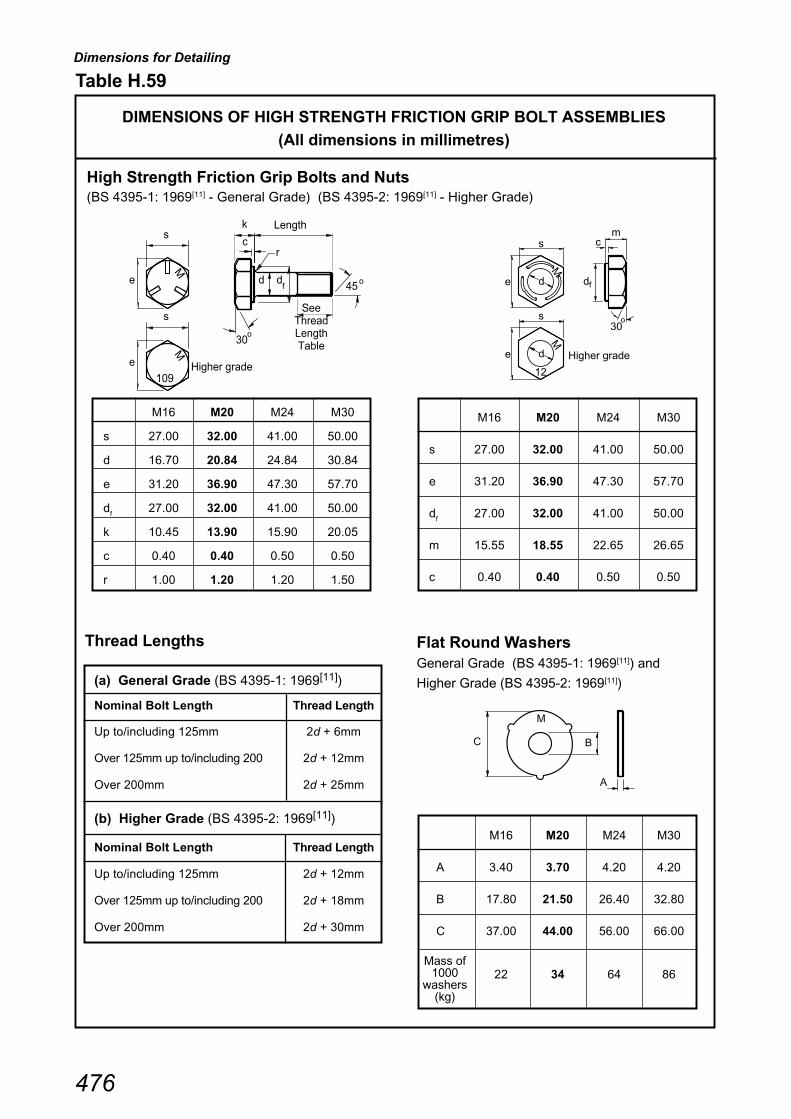
Dimensions for Detailing
476
Table H.59
DIMENSIONS OF HIGH STRENGTH FRICTION GRIP BOLT ASSEMBLIES
(All dimensions in millimetres)
High Strength Friction Grip Bolts and Nuts(BS 4395-1: 1969[11] - General Grade) (BS 4395-2: 1969[11] - Higher Grade)
M16 M20 M24 M30
s 27.00 32.00 41.00 50.00
d 16.70 20.84 24.84 30.84
e 31.20 36.90 47.30 57.70
df
27.00 32.00 41.00 50.00
k 10.45 13.90 15.90 20.05
c 0.40 0.40 0.50 0.50
r 1.00 1.20 1.20 1.50
M16 M20 M24 M30
s 27.00 32.00 41.00 50.00
e 31.20 36.90 47.30 57.70
df
27.00 32.00 41.00 50.00
m 15.55 18.55 22.65 26.65
c 0.40 0.40 0.50 0.50
(a) General Grade (BS 4395-1: 1969[11])
Nominal Bolt Length Thread Length
Up to/including 125mm 2d + 6mm
Over 125mm up to/including 200 2d + 12mm
Over 200mm 2d + 25mm
(b) Higher Grade (BS 4395-2: 1969[11])
Nominal Bolt Length Thread Length
Up to/including 125mm 2d + 12mm
Over 125mm up to/including 200 2d + 18mm
Over 200mm 2d + 30mm
Flat Round WashersGeneral Grade (BS 4395-1: 1969[11]) and
Higher Grade (BS 4395-2: 1969[11])
M16 M20 M24 M30
A 3.40 3.70 4.20 4.20
B 17.80 21.50 26.40 32.80
C 37.00 44.00 56.00 66.00
22 34 64 86
A
C B
M
fde
sM
de
s
12
30
mc
d
o
Higher grade
M
f
e
s
M
109
e
s
M
30
45
rc
Lengthk
dd
See Thread Length Table
o
o
Higher grade
Mass of1000
washers(kg)
Thread Lengths

Dimensions for Detailing
477
Dimensions (mm) for bolt size
M12 M16 M20 M24
A1 7 10 12 15
B1 13 17 22 25
C1 18 20 26 29
D1 Varies with overall bolt length (Lb) specified
E1 MinimumC1/2 + tc (for connections made to a single face or opposite faces)
B1/2 + A1 + D1 + tc (for connections made to adjacent faces)
Min Bolt Centres 30 40 50 60
Hole dia. RHS 12 16 20 24Hole dia. fitting 14 18 22 26
Notes:
(1) The thermal drilling process is limited to RHS thicknesses up to and including 12.5mm. For thicknesses of16mm and over, conventional drill and tap methods are recommended, although, due to the RHS materialstrength being lower than that of the grade 8.8 bolts, pull out strengths may be below the bolt tension capacity.
(2) Detailing must also comply with the requirements given in CHECK 1 of the appropriate design procedures.
(3) Additional information on thermal drilling is given in Appendix F.
Table H.60
DETAILING OF THERMAL DRILLING BOLT ASSEMBLIES
Width
Min bolt
centres
E
E1
p
Lt
ct
1
C1
b
B1
A1
D 1
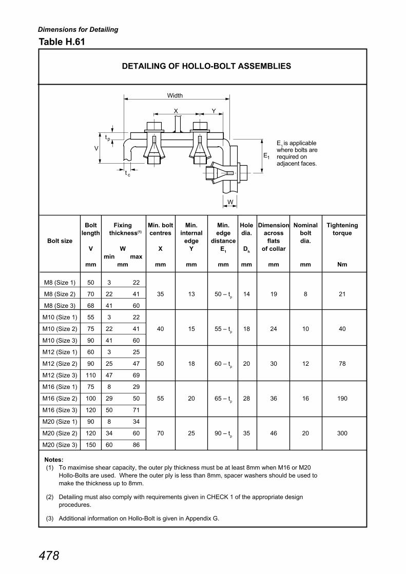
Dimensions for Detailing
478
Table H.61
DETAILING OF HOLLO-BOLT ASSEMBLIES
Bolt Fixing Min. bolt Min. Min. Hole Dimension Nominal Tighteninglength thickness(1) centres internal edge dia. across bolt torque
Bolt size edge distance flats dia.V W X Y E
1D
hof collar
min maxmm mm mm mm mm mm mm mm Nm
M8 (Size 1) 50 3 22
M8 (Size 2) 70 22 41 35 13 50 – tp
14 19 8 21
M8 (Size 3) 68 41 60
M10 (Size 1) 55 3 22
M10 (Size 2) 75 22 41 40 15 55 – tp
18 24 10 40
M10 (Size 3) 90 41 60
M12 (Size 1) 60 3 25
M12 (Size 2) 90 25 47 50 18 60 – tp
20 30 12 78
M12 (Size 3) 110 47 69
M16 (Size 1) 75 8 29
M16 (Size 2) 100 29 50 55 20 65 – tp
28 36 16 190
M16 (Size 3) 120 50 71
M20 (Size 1) 90 8 34
M20 (Size 2) 120 34 60 70 25 90 – tp
35 46 20 300
M20 (Size 3) 150 60 86
Notes: (1) To maximise shear capacity, the outer ply thickness must be at least 8mm when M16 or M20
Hollo-Bolts are used. Where the outer ply is less than 8mm, spacer washers should be used tomake the thickness up to 8mm.
(2) Detailing must also comply with requirements given in CHECK 1 of the appropriate designprocedures.
(3) Additional information on Hollo-Bolt is given in Appendix G.
Width
X Y
E1
p
V
t
W
ct
E1 is applicable
where bolts arerequired onadjacent faces.

Dimensions for Detailing
479
Table H.62
ENTERING AND TIGHTENING DIMENSIONS
(Approximate dimensions in millimetres)
Impact WrenchTorque Wrench
General grade Higher gradeBolt Size A B C Approximate Approximate
Torque (Nm) Torque (Nm)
M16 48 35 32 300 * 400 *
M20 60 44 40 600 * 800 *
M24 69 55 51 1000 * 1300 *
M30 85 70 60 1800 * 2700 *
Tightening Access
Bolt Size C1
C2
C3
M16 25 18 15
M20 32 22 19
M24 35 25 22
C1 = Clearance for tightening
C2 = Clearance for entering (holding bolt head)
C3 = Based on standard hardened washer
Podger Spanner
* Values are indicative of the torquerequired to achieve a shank tensionequal to the proof load. Site conditionsand equipment determine the actualtorque required. (+/- 20%)
(Refer to BS 4604: 1970)[31]
M16 60 460 90 *
M20 70 550 110 *
M24 85 640 130 *
M30 110 730 160 *
Bolt Size B LApproximate
Torque (Nm)
Values are indicative of torque achieved whenhand tigtened using a force of 250 N.
*
A
B
C600
60
B
A
L
B
C
C
C1
2
3
C2
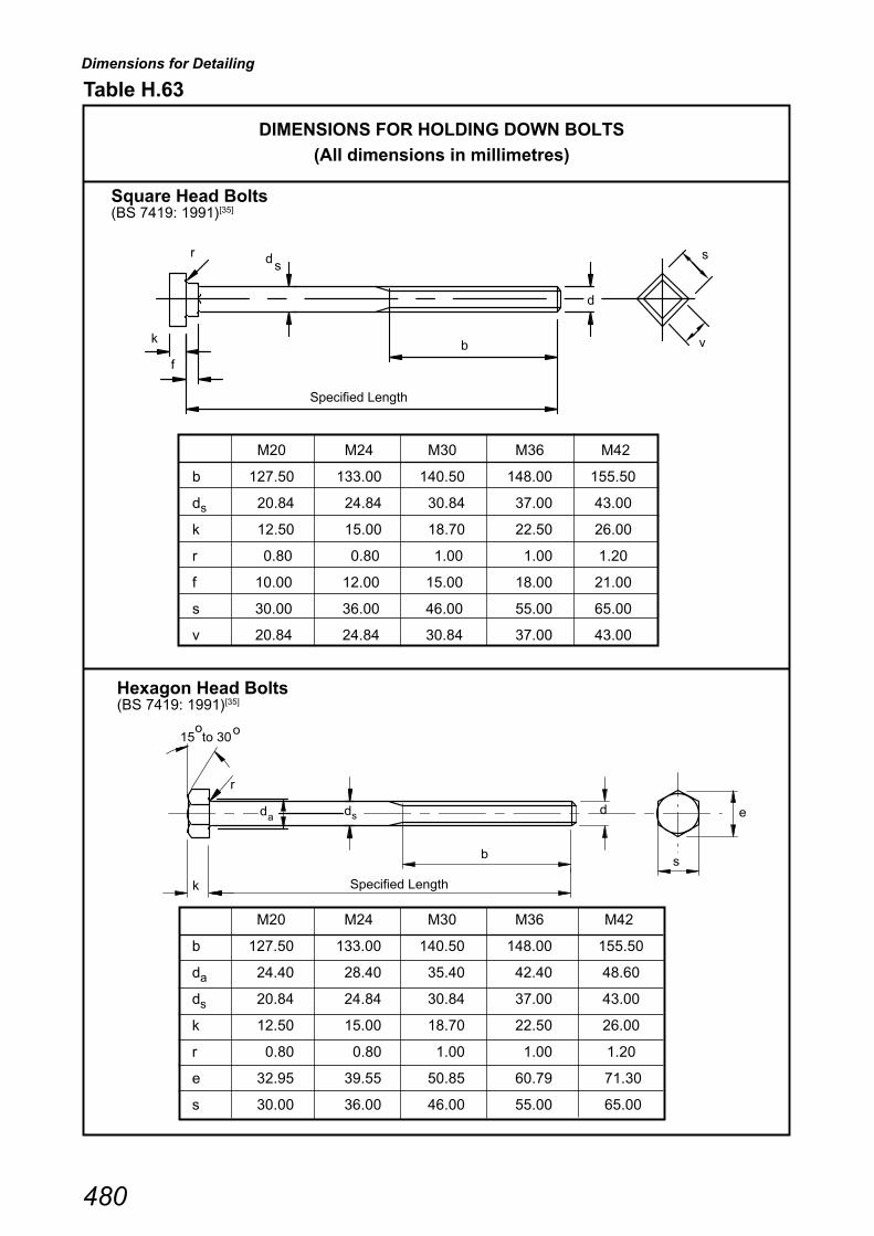
Dimensions for Detailing
480
M20 M24 M30 M36 M42
b 127.50 133.00 140.50 148.00 155.50
ds 20.84 24.84 30.84 37.00 43.00
k 12.50 15.00 18.70 22.50 26.00
r 0.80 0.80 1.00 1.00 1.20
f 10.00 12.00 15.00 18.00 21.00
s 30.00 36.00 46.00 55.00 65.00
v 20.84 24.84 30.84 37.00 43.00
Table H.63
DIMENSIONS FOR HOLDING DOWN BOLTS
(All dimensions in millimetres)
Hexagon Head Bolts(BS 7419: 1991)[35]
M20 M24 M30 M36 M42
b 127.50 133.00 140.50 148.00 155.50
da 24.40 28.40 35.40 42.40 48.60
ds 20.84 24.84 30.84 37.00 43.00
k 12.50 15.00 18.70 22.50 26.00
r 0.80 0.80 1.00 1.00 1.20
e 32.95 39.55 50.85 60.79 71.30
s 30.00 36.00 46.00 55.00 65.00
Square Head Bolts(BS 7419: 1991)[35]
d
b
Specified Length
k
f
r s
v
ds
15 to 30
r
k
ddd
b
Specified Length
e
s
sa
o o

������� ����� �����
��������
������� �� �� �� ����� ���� �� �� ���
���������� �� �� �� ����� ������� ��� ��� ��� ��
���� ������� ������� ��� ����� ������� ������� ���� ����� �������
� � � � � � � � �
!�"# ## ## ## ## ## ## ## ## ## #�
#�
�#�
����������� � � ����� ������ ����� ���� ���� ���� ��� � ��� �� ��� ��� ���
����������� � � ���� ����� ����� ��� ��� ���� ��� �� ��� �� ��� ��� ��
���������� � � � ��� ������ ����� ���� ��� ���� ����� �� ��� � ���� ���� ���
����������� � � ���� ������ ����� ���� ���� ���� ����� �� ��� � ���� ��� ���
������������ � � ����� ������ ����� ��� ��� ���� ����� �� ��� �� ���� �� ���
����������� � � ���� ��� ����� ���� ���� ���� ����� �� ��� �� ���� ���� ��
����������� � � ���� ���� ����� ���� ���� ���� ����� �� ��� �� ���� ���� ��
������������ � � ����� ��� ����� ���� ���� ���� ����� �� ��� �� ���� ���� ���
����� ���� � ����� ���� ����� ���� ���� ���� �� �� ��� �� ���� ��� ��
����� ���� � ����� ���� ����� ��� ���� ���� �� �� ��� �� ���� �� ��
��������� � ���� ���� ��� ��� ���� ��� ����� �� ��� �� ���� ���� ���
���������� � ����� ���� ����� ��� �� ��� ����� �� ��� �� �� ���� ���
���������� � ����� ���� ����� ��� ��� ��� ����� �� ��� �� �� ���� ���
���������� � ���� ���� ����� ���� ���� ��� ����� �� ��� �� ��� ��� ���
����� ����� � ����� ���� ���� ���� ���� ��� ��� �� ��� �� ���� ���� ��
����� ��� � � ���� ���� ���� ��� ��� ��� ��� ��� �� �� ���� ��
����� ���� � ��� ���� ��� ���� ���� ��� ��� ��� �� ��� ���� ���
������� ���� ��� ����� ���� ���� ���� ����� �� ��� �� ���� ���� ���
�������� ���� ���� ���� ���� ���� ���� ����� ��� �� ���� ���� ���
�������� ���� ���� ����� ���� ��� ���� ����� � ��� �� ���� ��� ��
��������� ���� ���� ����� ���� ���� ���� ����� � ��� �� ���� ��� ��
���������� ���� ��� ����� ���� ��� ���� ����� ��� �� ���� ���� ��
����������� ����� ���� ����� ���� ���� ���� ����� ��� �� ���� ���� ��
����������� ����� ����� ���� ���� ��� ���� ����� � ��� �� ���� ���� ��
����������� ����� �� ����� ��� ���� ���� ����� � ��� �� ���� ���� ��
����������� ����� ����� ����� ���� ���� ���� ����� �� ��� �� ���� ���� ���
��������� ��� ����� ���� ���� ���� ���� ����� ��� �� ���� ���� ���
���������� ���� ����� ����� ���� �� ���� ����� � ��� �� ��� ���� ��
������ ���� ��� ���� ����� ���� ���� ��� ���� ��� �� ���� ���� ��
������ ���� ����� ����� ���� ��� ��� ��� ���� � ��� �� ��� ��� ��
������ ���� ����� ���� ����� ���� ��� ��� ���� � ��� �� ���� ���� ���
������ ���� ����� ����� ���� ���� ���� ��� ���� ��� �� ��� ���� ��
����������� ����� ����� ���� ��� ���� ��� ���� � ��� �� ��� ���� ���
���������� ���� ���� ����� ���� ���� ��� ���� � ��� �� ���� ��� ��
����������� ����� ���� ����� ���� ��� ��� ���� ��� �� ��� ���� ��
�������� � ��� ����� ���� ���� ���� ��� ���� ��� �� ���� ���� ��
���������� ���� ����� ����� �� ���� ��� ���� ��� �� ���� ���� ���
� ������ � �� ���� � � ���� �����
� ����� �������������
����
��#������� ��� ��������
���������� � ������ ���
�� ������� ����
�� ���� ����
����!���� ������ ���
�������� ���!��
�
�
�
�
�
�
�
���
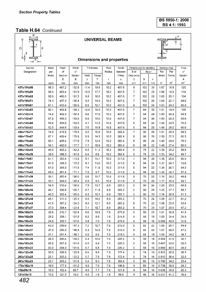
������� ����� �����
�������������������
������� �� �� �� ����� ���� �� �� ���
���������� �� �� �� ����� ������� ��� ��� ��� ��
���� ������� ������� ��� ����� ������� ������� ���� ����� �������
� � � � � � � � �
!�"# ## ## ## ## ## ## ## ## ## #�
#�
�#�
���� �� � ��� ���� ���� ���� ��� ���� ���� � ��� �� ��� ��� ���
���� ��� ��� ����� ��� ���� �� ���� ���� ��� �� ���� ���� ���
���� ���� ���� ����� ���� � ���� ���� ���� ��� �� ���� ���� ���
���� ��� ��� ���� ���� �� ���� ���� ���� ��� �� ���� ���� ���
���� ��� ��� ����� ��� ��� ��� ���� ���� � ��� �� ���� ���� ����
��������� ���� ����� ����� ���� ��� ���� ���� �� �� ���� ���� ���
�������� ��� ����� ����� �� ��� ���� ���� �� �� ���� ���� ���
�������� ��� ����� ����� �� ���� ���� ���� �� �� ���� ���� ����
��������� ��� ����� ���� ��� ���� ���� ���� � �� �� ��� ��� ���
��������� ���� ���� ����� �� ��� ���� ���� � �� �� ���� ���� ����
�������� ��� ����� ��� �� ���� ���� ����� � �� ���� ���� ���
�������� ��� ���� ���� ��� ���� ���� ����� � � �� ���� ���� ����
��������� ���� ����� �� � ���� ���� ����� � � �� ��� ���� ���
��������� ���� ����� �� � ��� ���� ����� � � �� ���� ��� ���
���������� ���� ����� ����� ��� ���� ���� ����� � � �� ���� ��� ����
��������� ��� ���� ����� ��� ��� ���� ����� � � �� ���� ���� ��
�������� ��� ����� ���� �� ��� ���� ����� � �� ���� ���� ����
�������� ��� ����� ���� ��� ���� ���� ����� � � �� ��� ���� ���
��������� ���� ����� ���� �� ���� ���� ����� � � �� ���� ��� ���
��������� ���� ����� ���� �� � ���� ����� � � �� ���� ���� ���
�������� ��� ����� ����� ��� ��� ���� ����� � � �� ���� ���� ���
��������� ���� ���� ����� ��� ��� ���� ����� � � �� ��� ���� ����
���������� ���� ����� ���� � ��� �� ����� � � �� ���� ���� ����
���������� ���� ����� ���� �� ���� �� ����� � � �� ���� ��� ���
���������� ���� ����� ����� ��� ���� �� ����� � � �� ���� ���� ����
��������� ���� ����� ����� �� ���� �� ����� � �� ��� ��� ����
��������� ��� ���� ����� ��� ���� �� ����� � � �� ���� ���� ����
�������� ��� ����� ����� �� ��� �� ����� � � �� ��� ��� ���
���������� ���� ���� ����� ��� ���� �� ��� � �� �� ���� ���� ����
���������� ���� ���� ����� ��� ��� �� ��� � �� �� ���� ���� ���
���������� ���� ����� ����� ��� �� �� ��� � �� �� ��� ���� ����
���������� ���� ���� ���� �� ��� �� ���� � �� �� ���� ���� ����
��������� ��� ����� ����� ��� ��� �� ���� � �� �� ��� ��� ���
���������� ���� ����� ����� ��� ��� �� ���� � �� �� ���� ���� ��
���������� ���� ����� ����� ��� ���� �� ����� � �� �� ���� ��� ����
���������� ���� ���� ���� ��� ��� �� ����� � �� �� ��� ���� ����
���������� ���� ����� ����� �� ��� �� ����� � �� �� ���� ���� ����
���������� ���� ����� ���� ��� �� �� ���� � � �� ���� ���� ����
���������� ���� ����� ����� �� �� �� ���� � � �� ���� ���� ����
���������� ���� ����� ����� ��� �� �� ���� � �� �� ��� ���� ���
�������� ��� ��� ����� ��� � �� ����� � �� �� ���� ���� ����
����� ��� ���� ����� ��� ��� � �� ����� � �� �� ����� ��� ����
������� ���� ���� ��� ��� �� �� ��� � �� �� ���� ���� ����
�� ������� ����
�� ���� ����
����
��#������� ��� �������� ������ ���
���������� � ������ ���
�������� ���!�
����!����
�
�
�
�
�
�
�
�
���

������� ����� �����
���������
������� �� �� �� ����� ���� �� �� ���
���������� �� �� �� ����� ������� ��� ��� ��� ��
���� ������� ������� ��� ����� ������� ������� ���� ����� �������
� � � � � � � � �
!�"# ## ## ## ## ## ## ## ## ## #�
#�
�#�
����������� � ���� ���� ����� ��� �� ���� ���� �� ��� � ���� ��� ���
����������� � ����� ����� ����� ���� ��� ���� ���� �� ��� �� ��� ��� ��
���������� � ���� ����� ����� ���� ���� ���� ���� �� ��� � ���� ��� ��
��������� � � ���� ���� ���� ���� ��� ���� ���� � ��� �� ���� ���� ���
����������� � ��� ����� ����� ���� ��� ���� ���� �� ��� �� ���� ��� ���
���������� � ���� ���� ��� ���� ���� ���� ���� �� ��� �� ���� ���� ���
����������� � ����� ����� ���� ���� ���� ���� ���� �� ��� �� ���� �� �
����������� � ���� ���� ��� ���� ��� ���� ���� �� �� �� ��� ���� ��
��������� � ��� ����� ���� ���� ���� ���� ���� �� �� ��� ���� ���
����������� � ���� ����� ���� ���� ��� ���� ���� � �� �� ���� ���� ��
���������� � ���� ����� ����� ���� ��� ���� ���� �� �� ���� ���� ���
����������� ���� ����� ����� ���� ���� ���� ���� �� ��� �� ��� ���� ���
����������� ����� ����� ����� ���� �� ���� ���� �� ��� �� ��� �� ���
��������� � ���� ��� ����� ��� ���� ���� ���� �� ��� �� ��� ��� ���
����������� ����� ���� ����� ���� ���� ���� ���� �� ��� �� ���� ���� ���
���������� ���� ����� ���� ���� ��� ���� ���� ��� �� ���� ���� ��
����������� ��� ����� ���� ���� ��� ���� ���� � ��� �� ���� ���� ���
�������� �� ��� ����� � ���� ���� ���� ��� �� �� ���� ���
���������� ���� ���� ����� ��� ��� ��� ����� �� ��� �� ���� ��� ���
����������� ����� ���� ����� ���� ���� ��� ����� �� ��� �� ���� ��� ���
���������� ���� ���� ����� ���� ���� ��� ����� � ��� �� ���� ���� ���
��������� ��� ����� ����� ���� ��� ��� ����� ��� �� ���� ��� ���
��������� ��� ����� ����� ��� ���� ��� ����� � ��� �� ��� ���� ���
���������� ���� ����� ���� ��� ���� ���� ����� � ��� �� ���� ���� ���
��������� ��� ����� ����� ���� ��� ���� ����� ��� �� ���� ��� ���
���������� ���� ���� ����� �� ���� ���� ����� ��� �� ���� ���� ���
���������� ���� ����� ����� � ���� ���� ����� � ��� �� ���� ���� ����
���������� ���� ����� ����� �� ���� ���� ����� � ��� �� ��� ���� ���
��������� ��� ����� ����� ��� ���� �� ����� � �� �� ���� ��� ���
���������� ���� ���� ���� ��� �� �� ����� � �� �� ���� ���� ����
���������� ���� ����� ����� ��� ��� �� ����� � �� �� ���� ��� ���
� ����� �������������
�� ������� ����
�� ���� ����
����
�������� "# �!��
���������� � ������ ���
����!���� ������ �����#������� ��� ��������
�
�
�
��
�
�
�
���
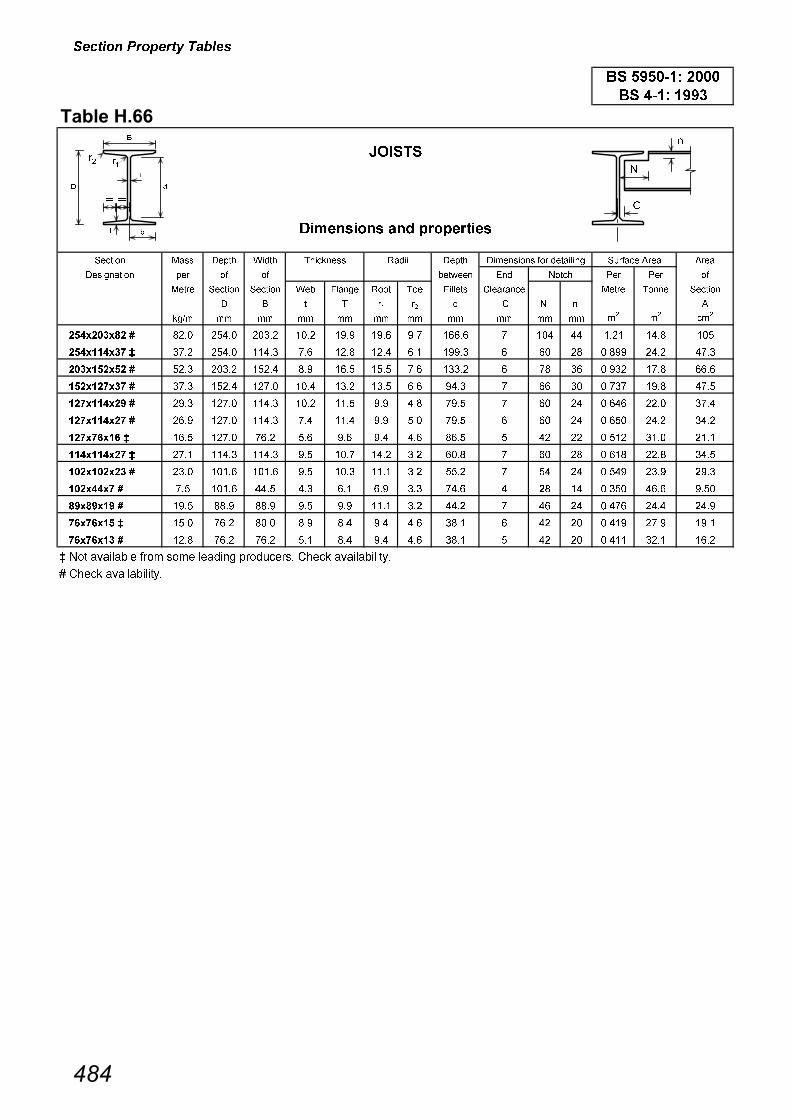
������� ����� �����
��������
������� �� �� �� ����� �� �� ���
���������� �� �� �� ������� ��� ��� ��� ��
���� ������� ������� ��� ����� ���� ��� ������� ������� ���� ����� �������
� � � � �� �� � � � �
!�"# ## ## ## ## ## ## ## ## ## ## #�
#�
�#�
���������� � ���� ����� ����� ���� �� ��� � ����� ��� �� ���� ���� ���
��������� � ��� ����� ����� �� ���� ���� ��� ��� � �� �� ��� ���� ���
���������� � ���� ����� ����� �� ���� ���� �� ����� � � �� ���� ��� ����
�������� � ��� ����� ���� ���� ���� ���� ��� ��� �� �� ��� ��� ���
�������� � ��� ���� ����� ���� ���� � ��� �� �� �� ����� ���� ���
�������� � ��� ���� ����� �� ���� � ��� �� � �� �� ����� ���� ����
������� � ���� ���� ��� ��� �� �� ��� ���� � �� �� ����� ���� ����
��������� � ��� ����� ����� �� ��� ���� ��� ���� �� �� ����� ���� ����
���������� � ���� ����� ����� �� ���� ���� ��� ���� �� �� ���� ��� ���
������� � �� ����� ���� ��� ��� �� ��� ��� � �� �� ����� ���� ���
� �� �� � ��� ��� ��� �� � ���� ��� ���� �� �� ���� ���� ���
������ � ���� ��� ���� �� ��� �� ��� ���� � �� �� ���� �� ���
������ � ���� ��� ��� ��� ��� �� ��� ���� � �� �� ����� ���� ����
� ��� ��������� � �! �!� ���"�� # �"$�� � ����� �������������
� ����� �������������
����!����
$#��%�
���������� � ������ ���
��#������� ��� ��������
����
����
�� ������� ����
�� ���� ����
������ ���
�
��
�
�
�
�
��
�
�
��
�
�
�
���
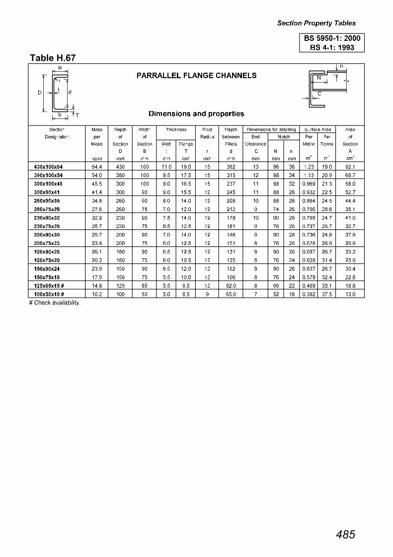
������� ����� �����
���������
������� �� �� �� ����� ���� �� �� ���
���������� �� �� �� ����� ������� ��� ��� ��� ��
���� ������� ������� ��� ����� ������� ������� ���� ����� �������
� � � � � � � � �
!�"# ## ## ## ## ## ## ## ## ## #�
#�
�#�
���������� ���� ��� ��� ���� ��� �� ��� �� � �� ���� ��� ����
���������� ���� ��� ��� �� ��� �� ��� �� � �� ���� ��� ���
���������� ���� ��� ��� �� ���� �� �� �� � �� ��� ���� ����
���� ���� ���� ��� � �� ���� �� ��� �� �� �� ���� ���� ���
���� ���� ���� ��� � ��� ���� �� ��� �� �� �� ����� ���� ����
�������� ��� ��� � �� ���� �� ��� � �� ��� ���� ����
���� ���� ���� ��� � �� ���� �� �� �� � �� ��� ��� ����
�������� ��� ��� � ��� ���� �� ��� � �� ��� ��� ���
���� ���� �� ��� � �� ���� �� ��� � �� ���� ���� ��
�������� ���� ��� � ��� ���� �� ��� � � �� ���� ��� ��
���� ���� ���� ��� � ��� ���� �� ��� � �� ��� ��� ����
�������� ���� ��� � ��� ���� �� ��� � � �� ����� ���� ���
���� ���� ��� ��� � ��� ���� �� ��� � �� ���� ��� ����
�������� �� ��� � ��� ���� �� ��� � � �� ��� ���� ����
��������� � ���� ��� �� ��� �� �� ���� � �� �� ���� ���� ����
��������� � ���� ��� �� ��� ��� ���� �� �� ����� ��� ����
� ����� �������������
�� ������� ����
�� ���� ����
����
������ �����#������� ��� ��������
&���� � ' ��(� ")���� �
���������� � ������ ���
����!����
�
�
��
�
�
���

������� ����� �����
��������
�� ��#������ ���
�� ��
��$� ����!���� ���� ���� ��� �������
� % � � �� �� �
## ## !�"# ## ## �# �#�
������� �� ��� ���� ��� ���� ���
������� �� �� ���� ��� ���� ���
������� �� ���� ���� ��� ���� ���
������� �� ���� ���� ��� ���� ����
������� �� ���� ���� ���� ���� ����
������� �� ���� ���� ���� ���� ����
������� �� ��� ���� ���� ���� ����
������� �� ���� ���� ���� ���� ���
������� �� ���� ���� ���� ���� ����
������� �� ���� ���� ���� ���� ���
������� �� ���� ���� ���� ���� ����
������� � ��� ���� ���� ���� ����
������� �� ��� ���� ���� ���� ����
������� �� ��� ���� ���� ��� ���
������� �� ���� ���� ���� ���� ���
������� � ���� ���� ���� ��� ����
�� � �� ��� ���� ���� ���� ����
�� � �� ���� ���� ���� ���� ���
�� � � ��� ���� ���� ���� ���
�� � ��� ���� ���� ���� ����
����� �� � ��� ���� ���� ���� ����
����� � � ��� ���� ���� ���� ����
��� � � �� ��� ���� ���� ����
��� � � ���� ��� ���� ���� ���
��� � ��� ��� ���� �� ���
��� � � ���� ��� ���� ��� ����
����� � ���� ��� ���� ���� ���
����� � � �� ���� ���� �� ���
����� � � ���� ���� ���� ��� ���
����� � � ��� ���� ���� ���� ����
����� � � ��� ��� ���� ���� ���
����� � � �� ��� ���� ���� ����
����� � � ���� ��� ���� ���� ���
����� ��� � ���� ��� ���� ���� ���
����� � � �� ���� ���� ���� ��
����� � � ���� ���� ���� ���� ����
����� � � ��� ���� ���� ���� ���
����� � � ��� ���� ���� ���� ���
����� � � ���� ���� ���� ����� ���
����� � � ���� ���� ��� ���� ����
����� � � ���� ���� ��� ���� ����
����� � � ����� ���� ��� ���� ����
� ��� ��������� � �! �!� ���"�� # �"$�� � ����� �������������
� ����� �������������
� � ��� "����� � �! ��� ���� �� ��� ��� �� ��� ��� � �� � ������
������������
����������
�� ������� ����
�� �� ����*��� ����
�+�� ��( ��
���������� � ������ ����
�
�
���
� �
� �� �
�
�
�
�
�
�
� �
�
�
���

������� ����� �����
���������
���+�� ��( ��
���������� � ������ ���
�� ����� ���
�� �%�� %&% ��
��$� ����!���� ���� ���� ��� �� �������
�%�� �&�
� % � � �� �� �� �� �� �
## ## !�"# ## ## �# �# �#�
������� �� ��� ���� ��� ���� ���� ���� ����
������� �� ��� ���� ��� ���� ��� ����� ����
������� �� ���� ���� ��� ���� ���� ����� ����
������� �� ���� ���� ��� ��� ���� ����� ����
������� �� ��� ���� ��� ��� ���� ����� ����
������� �� ���� ���� ��� ��� ���� ����� ���
���� � �� ��� ���� ���� ���� ���� ����� ���
���� � �� ���� ���� ���� ���� ���� ����� ���
���� � �� ���� ���� ���� ���� ���� ����� ����
����� �� ���� ���� ���� ���� ���� ����� ���
����� �� ���� ���� ���� ���� ��� ����� ���
����� �� ��� ���� ���� ���� ���� ����� ���
����� �� ��� ���� ���� ���� ���� ����� ���
����� �� ���� ���� ���� ���� ��� ���� ���
����� � ���� ���� ���� ���� ���� ����� ����
����� �� ���� ���� ���� ��� ���� ����� ��
����� �� ���� ���� ���� ��� ��� ����� ����
����� � ���� ���� ���� ���� ��� ���� ����
������ �� ���� ���� ���� ���� ���� ����� ����
������ � �� ���� ���� ��� ���� ����� ���
������ �� ���� ���� ���� ���� ����� ����
������ � � �� ���� ���� ���� ���� ����� ����
������ � � ���� ���� ���� ���� ���� ����� ���
����� � ��� ���� ���� ���� ���� ����� ���
����� � � �� ��� ���� ��� ���� ����� ���
����� � � ���� ��� ���� ���� ����� ����� ���
���� � � �� ��� ���� ���� ��� ����� ���
���� � � ���� ��� ���� ���� ���� ����� ��
���� � � ���� ��� ���� ���� ���� ����� ���
����� � � ���� ���� ���� �� ���� ��� ����
����� � � ���� ���� ���� ���� ���� ����� ����
����� � � ��� ���� ���� ��� ��� ����� ��
����� � � ���� ���� ���� ��� ����� ���� ����
����� � � ��� ���� ���� ��� ���� ����� ���
����� � � ���� ���� ���� ���� ���� ����� ���
����� � � ��� ���� ���� ���� ����� ����� ����
����� � � �� ���� ���� ��� ����� ����� ����
����� � � ���� ���� ���� ���� ����� ����� ����
����� � � ���� ���� ���� ��� ����� ���� ����
� ��� ��������� � �! �!� ���"�� # �"$�� � ����� �������������
� ����� �������������
�� � ��� "����� � �! ��� ���� �� ��� �� � ��� �� ��� ��� � �� � ������
�� � ��� "����� � �! ��� ���� �� ��� ��� ��� �� ��� ��� � �� � ������
�� �� ����*��� ����
�� ������� ����
����������
��#������������������
�
� ��
�
� ��
�
�
�
�
�
����
��
�
�
�
�
�
���
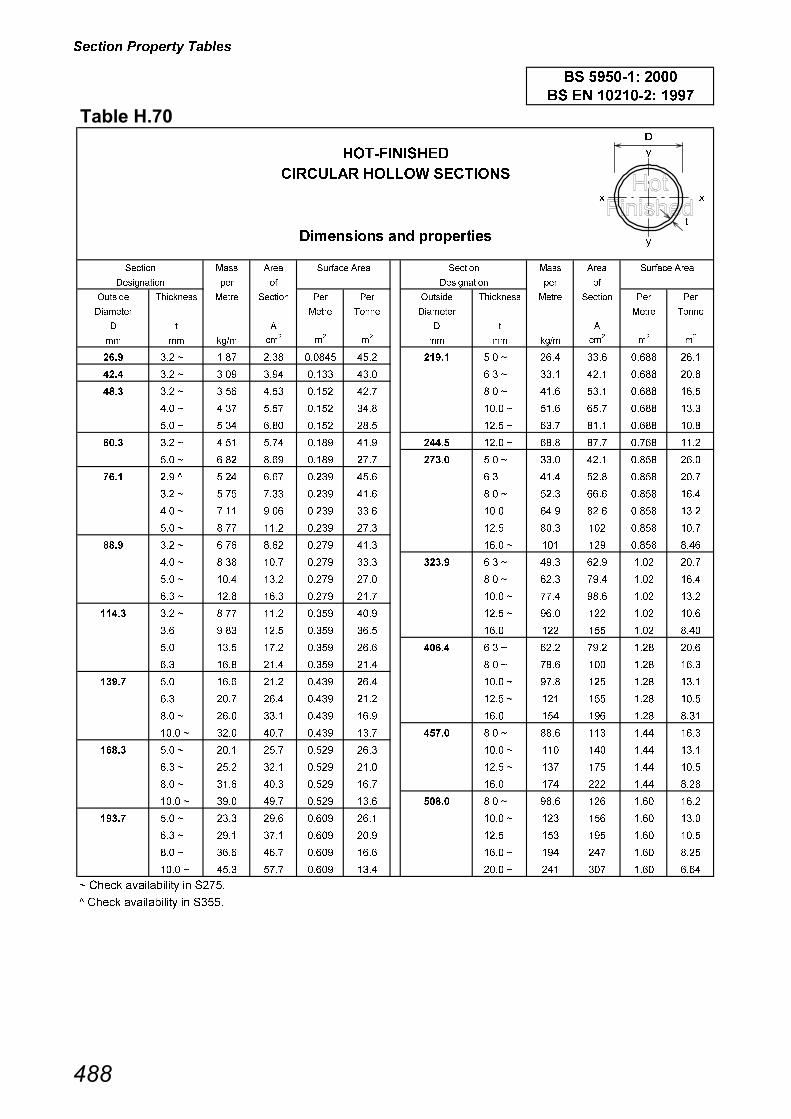
������� ����� �����
��������
����������
���� ��� ������ �������
��������� ��� ����������
���� ���� ���� ����
��� � ��� �
��� �� �� ������ ����� ���� �� ��� ��� ��� �� �� ������ ����� ���� �� ��� ���
� ������ ����� ����� � ������ ����� �����
� � � � � �
�� �� ���� ���
��
��
�� �� ���� ���
��
��
���� ��� � ���� ���� ��� ��� ����� �� � ��� ���� ���� ����
���� ��� � �� �� ���� �� ����� ��� � ���� ��� ���� ���
���� ��� � ���� ��� ���� ��� ����� �� � ��� ���� ���� ����
���� � � ��� ���� ���� ��� ����� �� � ���� ���� ���� ����
���� �� � ��� ��� ���� ���� ����� ���� � ���� ���� ���� ���
��� ��� � ��� ��� ��� �� ���� ��� � ���� ���� ���� ����
��� �� � ���� ��� ��� ���� ���� �� � ��� ��� ���� ���
���� �� � ��� ���� ��� ��� ���� ��� �� ���� ���� ���
���� ��� � ���� ���� ��� ��� ���� �� � ���� ���� ���� ���
���� � � ���� �� ��� ���� ���� �� �� ���� ���� ����
���� �� � ���� ���� ��� ���� ���� ���� ��� �� ���� ���
���� ��� � ���� ���� ��� ��� ���� ��� � �� �� ���� ���
���� � � ���� ��� ��� ���� ����� ��� � �� ��� ��� ���
���� �� � �� ���� ��� ��� ����� �� � ���� � � ��� ���
���� ��� � ���� ���� ��� ���� ����� �� � ��� ��� ��� ����
����� ��� � ���� ���� ��� � ����� ���� � �� ��� ��� ���
����� ��� ��� ���� ��� ���� ����� ��� ��� ��� ��� ��
����� �� ���� ���� ��� ���� ���� ��� � ���� � �� ���� ���
����� ��� ���� ��� ��� ��� ���� �� � ���� � ���� ����
����� �� ���� ���� �� ��� ���� �� � ��� ��� ���� ����
����� ��� ��� ��� �� ���� ���� ���� � ��� ��� ���� ���
����� �� � ��� ���� �� ��� ���� ��� �� � � ���� ����
����� �� � ��� �� �� ���� ��� �� � ���� ��� �� ����
����� �� � ��� ���� ��� ���� ��� �� � �� � �� ����
����� ��� � ���� ���� ��� ��� ��� ���� � ��� ��� �� ���
����� �� � ���� �� ��� ���� ��� ��� �� ��� �� ����
����� �� � � � �� ��� ���� �� �� � ��� ��� ��� ����
����� �� � ���� � �� �� ���� �� �� � ��� ��� ��� ���
����� ��� � � �� ���� �� �� �� ���� ��� � � ��� ���
����� �� � ���� ��� �� ���� �� ��� � � �� ��� ����
����� �� � ��� ���� �� ��� �� �� � �� �� ��� ���
� ����� ������ � � �����
� ����� ������ � � �����
�� � �� ��� ! �""#
�� $"$���! ���
��� ���� ��
������ ���������� �������� ��
��� ���� ��
���� ��
�
��
�
�
�
���

������� ����� �����
���������
����������
�% �� ������ �������
��������� ��� ����������
���� ���� ���� ����
��� � ��� �
� �� �� ������ ����� ���� �� ��� ��� � �� �� ������ ����� ���� �� ��� ���
����� ����� ����� �����
� � � � � � � � � �
�� �� ���� ���
��
��
�� �� ���� ���
��
��
� �� � ��� ��� �� � �� ��� �� � ���� ���� ���� ���
� ��� � ��� ���� �� � ��� ��� ��� ���� ���� ��� ���
� � ��� ��� �� ���� ��� �� � ���� �� ��� ����
� �� ���� ���� ���� ���� ��� �� ��� �� ��� ����
� ��� � ���� ��� ��� ���� ��� ���� � ���� ���� ���� ���
��� �� � ��� ��� ���� �� ��� ��� � ���� ��� ��� ����
��� ��� � ���� ���� ���� ��� ����� �� � ��� ��� ���� ���
��� � � �� ��� ��� ���� ����� ��� � ��� ���� ��� ���
��� �� ��� ��� ���� ��� ����� �� � ���� �� ��� ����
��� ��� � ��� ���� ��� ���� ����� �� � ��� ��� ��� ����
��� �� � ���� ��� ��� ���� ����� ���� � ���� ���� ��� ���
��� ��� � �� �� ���� ���� ����� ��� � �� ��� �� ���
��� �� � � ���� ���� ���� ����� �� � ��� �� �� ���
��� ��� � ���� ���� ��� ���� ����� �� � ���� ��� �� ����
��� �� � ��� � �� ��� ���� ����� ���� � �� ���� ���� ���
��� ��� � ���� �� ���� ���� ����� ��� � ��� �� ��� ���
��� � � �� ��� ��� ��� ��� �� � �� ���� ���� ���
��� �� � ���� ��� ��� ���� ��� ��� � ��� �� ��� ���
��� ��� ��� ���� �� ��� ��� �� � ��� ��� ��� ����
��� �� � ���� ��� �� ���� ��� �� ���� �� ��� ����
��� ��� � ��� ���� ���� ���� ��� ���� � ���� ��� ���� ���
��� � � ��� ���� ��� ���� ��� ��� � �� ��� ��� ���
��� �� � ���� ���� ��� ���� ��� ��� � �� ��� � � ���
��� ��� � ���� ��� �� ���� ��� �� � ��� ���� � � ����
��� �� � ��� ���� ��� ��� ��� �� � ��� � � � ����
��� � ��� ���� �� ���� ��� ���� � �� ��� � �� ���
��� �� ��� ���� ���� ���� ��� ��� � ��� �� � � ����
��� ��� ���� ���� ��� ���� ��� ��� � ���� ���� ���� ��
��� �� � ���� ���� ��� ���� ��� �� � ���� ��� ���� ����
��� �� ��� �� ��� ���� ��� �� � �� ��� ���� ���
����� �� � ���� ���� ��� ���� ��� ���� � ��� �� ���� ���
����� ��� ���� ���� �� �� ��� ��� � �� �� ���� ����
����� �� � ���� ���� �� ���� ��� �� � ��� � ���� ����
����� �� � ���� �� �� ���� ��� �� � �� ��� ���� ���
����� ���� � � ���� �� ��� ��� ���� � ��� ��� ���� ���
����� �� � ��� ���� ��� ��� ��� ��� � ��� ��� ���� ���
����� ��� � ���� ���� �� ��� ��� �� � ��� ��� ���� ���
����� �� � ���� ��� ��� ���� ��� ���� ��� � � ���� ��
����� �� � � �� ��� ��� ��� ��� � � � �� ���� ����
����� ���� � ��� ���� ���� ��� ��� �� � ��� � ���� ���
� ����� ������ � � �����
�� $"$���! ���
�� � �� ��� ! �""#
��� ���� ��
������ ���������� �������� ��
��� ���� ��
���� ��
�
�
�
��
�
�
���

������� ����� �����
���������
����������
�����& ��� ������ �������
��������� ��� ����������
���� ���� ���� ����
��� � ��� �
� �� �� ������ ����� ���� �� ��� ��� � �� �� ������ ����� ���� �� ��� ���
� � � � � ����� ����� � � � � � ����� �����
�� �� ���� ���
��
��
�� �� ���� ���
��
��
�� ��� � ���� �� ���� ��� ��� �� � ���� ���� ���� ���
��� �� � ��� ��� �� � �� ��� ��� � ���� ���� ��� ���
��� � � ��� ��� �� ���� ��� �� ���� �� ��� ����
��� �� � ���� ���� ���� ���� ��� �� ��� �� ��� ����
��� ��� � ���� ���� ���� ��� ��� ���� ���� ���� ���� ���
��� � � �� ��� ��� ���� ���� �� � ��� ��� ���� ���
��� �� � ��� ��� ���� ��� ���� ��� � ��� ���� ��� ���
��� ��� � ��� ���� ��� ���� ���� �� � ���� �� ��� ����
��� �� � ���� ��� ��� ���� ���� �� � ��� ��� ��� ����
�� ��� � �� �� ���� ���� ��� �� � �� ���� ��� ���
�� �� � � ���� ���� ���� ��� �� � ��� �� ��� ����
�� ��� � ���� ���� ��� ���� ��� �� � ��� �� ��� ����
�� �� � ���� ��� �� � ��� ��� ���� � ���� � �� ���� ���
�� ��� � ���� �� �� � �� ��� �� � �� ���� ���� ���
�� �� � ��� ���� ���� ���� ��� ��� ��� �� ��� ���
�� ��� � ���� ��� ��� ��� ��� �� � ��� ��� ��� ����
�� �� � ���� ��� ��� ���� ��� �� � ���� �� ��� ����
�� �� � � �� �� ��� �� ��� ���� ���� ��� ���� ���
��� ��� � ���� �� ���� ���� ��� ��� � �� ��� ��� ���
��� �� � ���� ��� ��� ���� ��� �� � ��� ��� ��� ����
��� ��� � ��� ���� �� ��� ��� �� � ���� �� ��� ����
��� �� � ���� ��� �� ���� ��� ��� � �� ��� � � ���
���� ��� � �� ���� ���� ���� ��� �� � ��� ���� � � ����
���� �� � ���� ���� ��� ���� ��� �� � ��� � � � ����
���� ��� � ���� ��� �� ���� ��� ���� � �� ��� � �� ���
���� �� � ��� ���� ��� ��� ��� ��� ��� �� � � ���
���� �� � ��� ���� ���� ���� ��� �� � ���� ��� ���� ����
���� ��� ���� ���� ��� ���� ��� �� � �� ��� ���� ���
���� �� ���� ���� ��� ���� ��� ���� � ��� �� ���� ���
���� �� � ��� �� ��� ���� ��� ��� � �� �� ���� ����
��� �� � ���� ���� ��� ���� ��� �� � ��� � ���� ����
��� ��� ���� � �� �� ��� ��� �� � �� ��� ���� ���
��� �� � ��� ���� �� ���� ��� ���� � ��� ��� ���� ���
��� �� � ���� � �� ��� ��� ��� ��� ��� ���� ���
��� ���� � ��� ��� ��� �� �� �� � �� ��� ���� ����
���� � � �� ��� �� ���� �� �� � ��� ��� ���� ���
���� �� � ���� ���� ��� ���� �� ���� � ��� � � ���� ��
���� ��� ���� ���� �� �� �� ��� � � � �� ���� ����
���� �� ���� ���� �� ���� �� �� � ��� � ���� ���
���� �� � ���� �� �� ����
� ����� ������ � � �����
� ����� ������ � � �����
������ ����
��� ���� ��
�� $"$���! ���
�� � �� ��� ! �""#
������ �������� ��
��� ���� ��
���� ��
�
�
�
��
�
�
���
Recommended