JOINING
PROCESSESNUMPON MAHAYOTSANUN DEPARTMENT OF MECHANICAL ENGINEERING KHON KAEN UNIVERSITY

INTRODUCTION
Joining can be categorized in terms of their common principle of operation as:Fusion welding involves melting and coalescing materials by means of heat, usually supplied by electrical or high-energy means. The processes consist of oxyfuel gas welding, consumable- and nonconsumable-elctrode arc welding, and high-energy-beam welding.Solid-state welding involves joining without fusion; that is, there is no liquid (mol-ten) phase in the joint. The basic categories of solid state welding are cold, ultra-sonic, friction, resistance, explosion welding, and diffusion bonding.Brazing and soldering use filler metals and involve lower temperatures than used in welding. The heat required is supplied externally.
Adhesive bonding is an important technology because of its unique advantages for applications requiring strength, sealing, insulation, vibration damping, and resis-tance to corrosion between dissimilar or similar metals. Included in this category are electrically conducting adhesives for surface-mount technologies.Mechanical fastening processes use a wide variety of fasteners, bolts, nuts, screws, and rivets. Joining nonmetallic materials can be accomplished by such means as mechanical fastening, adhesive bonding, fusion by various external or internal heat sources, diffusion, and preplating with metal.
Page 2
Page 3

OXYGENGAS WELDING
Oxyfuel gas welding (OFW) is a general term to describe any welding process that uses a fuel gas, combined with oxygen to produce a flame, as the source of the heat required to melt the metals at the joint. The most common gas welding processes uses acetylene. The proportion of acetylene and oxygen in the gas mixture is an important factor in oxyfuel gas welding. At a ratio of 1:1, that is, when there is no excess oxygen, the flame is considered to be neutral. With a greater oxygen supply, the flame can be harmful, especially for steels, because it oxidizes the metal; hence
it is known as an oxidizing flame. If oxygen is insufficient for full combustion, the flam is known as a reducing (having excess acetylene) or caburizing flame. Filler metals are used to supply additional metal to the weld zone during welding. They are available as filler rods or wire and may be bare or coated with flux. The purpose of the flux is to retard oxidation of the surfaces being welded, by generating a gas-eous shield around the weld zone.
Page 4

Page 5
Three basic types of oxyacetylene flames used in oxyfuel gas welding and cutting operations: (a) neutral flame; (b) oxidizing flame; (c) carburizing, or reducing, flame. (d) The principle of the oxyfuel gas welding operation.

PRESSUREGAS
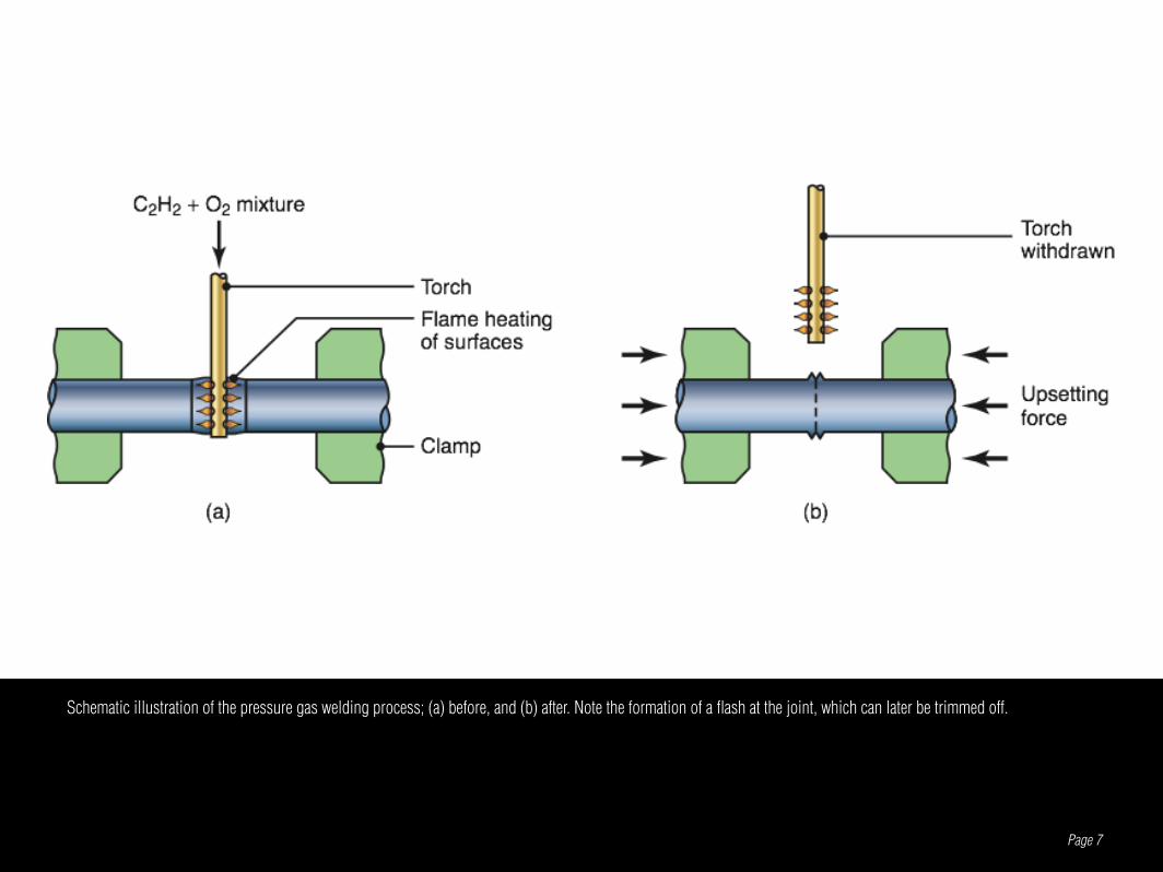
WELDINGIn this method, the two components to be welded are heated at their interface by means of a torch using and oxyacetylene gas mixture. After the interface begins to melt, the torch is withdrawn. An axial force is then applied to press the two components together and is maintained until the interface solidifies. Note the formation of a flash due to the upsetting of the joined ends of the two components.
Page 6
Page 7
Schematic illustration of the pressure gas welding process; (a) before, and (b) after. Note the formation of a flash at the joint, which can later be trimmed off.

ARC WELDINGPROCESSES
In arc welding, the heat required is obtained through electrical energy. Using either a consumable or a nonconsumable electrode (rod or wire), an arc is produced be-tween the tip of the electrode and the parts to be welded.
The heat input in arch welding can be calculated from the equation
Where H is the heat input l is the weld length V is the voltage applied I is the current v is the welding speed e is the efficiency of the process (from 75% for shielded arc welding to 90% for gas metal arc welding and submerged arc welding)v
VIelH
=
Page 8
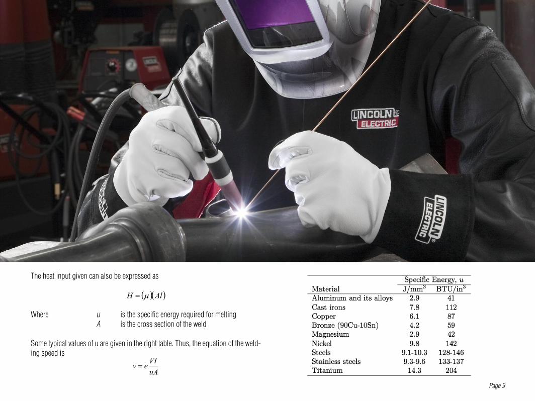
The heat input given can also be expressed as
Where u is the specific energy required for melting A is the cross section of the weld
Some typical values of u are given in the right table. Thus, the equation of the weld-ing speed is
( )( )AlH µ=
uAVIev =
Page 9
SHIELDEDMETAL ARC WELDING
In this process, the electric arc is generated by touching the tip of a coated electrode to the workpiece and then withdrawing it quickly to a distance sufficient to maintain the arc. The heat generated melts a portion of the electrode tip, its coating, and the base metal in the immediate area of the arc. A weld forms after the molten metal solidifies in the weld area. The electrode coating deoxidizes and provides a shielding gas in the weld area to protect it from the oxygen in the environment.
Page 10

Page 11
(a) Schematic illustration of the shielded metal arc welding process. About one-half of all large-scale industrial welding operations use this process. (b) Schematic illustra-tion of the shielded metal arc welding operation.
SUBMERGEDMETAL ARC WELDING
In submerged arc welding, the weld arc is shielded by granular flux (consisting of lime, silica, maganese oxide, calcium fluoride, and other elements) which is fed into the weld zone by gravity flow through a nozzle. The thick layer of flux completely covers the molten metal and prevents weld spatter and sparks and suppresses the intense ultraviolet radiation and fumes. The flux also acts as a thermal insulator, allowing deep penetration of heat into the workpiece. The unfused flux is recovered (using a recovery tube), treated, and reused. The consumable electrode is a coil of
Page 12
bare wire and is fed automatically through a tube (welding gun). Because the flux is fed by gravity, the SAW process is somewhat limited to welds in a horizontal or flat position, with a backup piece.

Page 13
Schematic illustration of the submerged arc welding process and equipment. Unfused flux is recovered and reused.

GASMETAL ARC WELDING
Page 14
In gas metal arc welding, the weld area is shielded by an external source of gas, such as argon, helium, carbon dioxide, or various other gas mixtures. In addition, deoxidiz-ers are usually present in the electrode metal itself, in order to prevent oxidation of the molten weld puddle. The consumable bare wire is fed automatically through a nozzle into the weld arc, and multiple weld layers can be deposited at the joint.

Page 15
(a) Gas metal arc welding process, formerly known as MIG welding (for metal inert gas). (b) Basic equipment used in gas metal arc welding operations.

FLUX-COREDARC WELDING
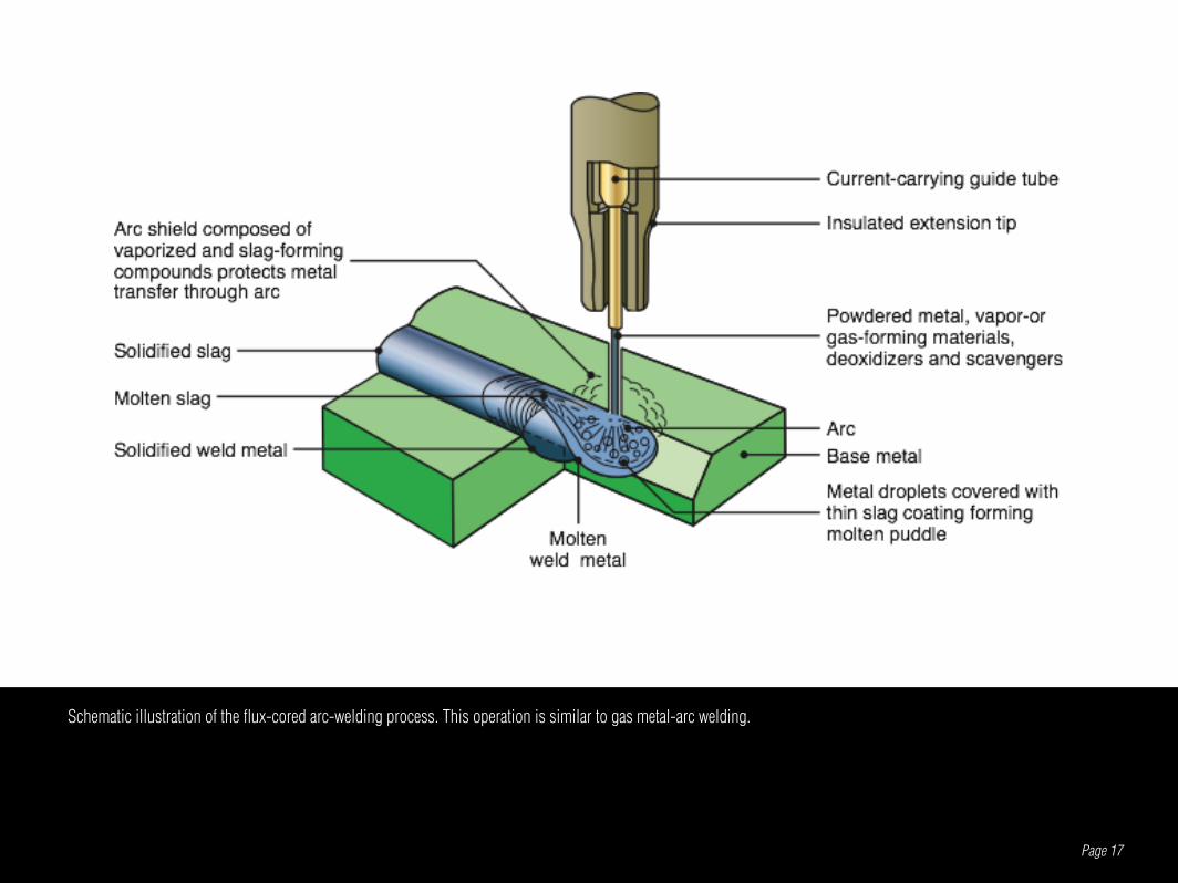
The flux-cored arc welding process is similar to gas metal arc welding, with the exception that the electrode is tubular in shape and is filled with flux. Cored elec-trodes produce a more stable arc, improve weld contour, and improve the mechani-cal properties of the weld metal. The flux-cored arc welding process combines the versatility of SMAW with the continuous and automatic electrode feeding feature of GMAW. It is economical and is used for welding a variety of joints with dif-ferent thicknesses, mainly with steels, stainless steels, and nickel alloys. A major
Page 16
advantage of FCAW is the ease with witch specific weld metal chemistries can be developed. This process is easy to automate and is readily adaptable to flexible manufacturing systems and robotics.
Page 17
Schematic illustration of the flux-cored arc-welding process. This operation is similar to gas metal-arc welding.
ELECTROGASWELDING
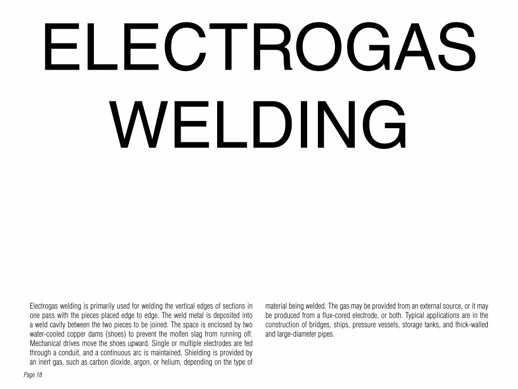
Electrogas welding is primarily used for welding the vertical edges of sections in one pass with the pieces placed edge to edge. The weld metal is deposited into a weld cavity between the two pieces to be joined. The space is enclosed by two water-cooled copper dams (shoes) to prevent the molten slag from running off. Mechanical drives move the shoes upward. Single or multiple electrodes are fed through a conduit, and a continuous arc is maintained. Shielding is provided by an inert gas, such as carbon dioxide, argon, or helium, depending on the type of
Page 18
material being welded. The gas may be provided from an external source, or it may be produced from a flux-cored electrode, or both. Typical applications are in the construction of bridges, ships, pressure vessels, storage tanks, and thick-walled and large-diameter pipes.

Page 19
Schematic illustration of the electrogas welding process.

ELECTRO-SLAG
WELDINGIn electroslag welding the arc is started between the electrode tip and the bottom of the part to be welded. Flux is added and melted by the heat of the arc. After the molten slag reaches the tip of the electrode, the arc is extinguished; energy is supplied continuously through the electrical resistance of the molten slag. Single or multiple solid as well as flux-cored electrodes may be used, and the guide may be nonconsumable or consumable. Welding is done in one pass. The weld quality is good, and the process is used for heavy structural steel sections, such as heavy machinery and nuclear reactor vessels.
Page 20

Page 21
Equipment used for electroslag welding operations.

GAS TUNGSTEN
ARC WELDINGIn gas tungsten arc welding, fomerly known as TIG welding (tungsten inert gas), a filler metal is typically supplied from a filler wire. However, welding also may be done without filler metals, such as in welding close-fit joints. The composition of filler metals must be similar to that of the metals to be welded. Flux is not used and the shielding gas is usually argon or helium, or a mixture of the two. Because the tungsten electrode is not consumed in this operation, a constant and stable arc gap is maintained at a constant level of current. The GTAW process is used for a wide
Page 22
variety of applications and metals, particularly aluminum, magnesium, titanium, and refractory metals, and it is especially expensive than SMAW, but it provides welds with very high quality and good surface finish.

Page 23
(a) Gas tungsten arc welding process, formerly known as TIG welding (for tungsten inert gas). (b) Equipment for gas tungsten arc welding operations.

PLASMAARC
WELDINGIn plasma arc welding, a concentrated plasma arc is produced and directed toward the weld area. Plasma is ionized hot gas, composed of nearly equal numbers of electrons and ions. The plasma is initiated between the tungsten electrode and the orifice, using a low-current pilot arc. Unlike the arc in other processes, the plasma arc is concentrated, because it is forced through a relatively small orifice. When a filler metal is used, it is fed into the arc, as in GTAW. Arc and weld-zone shielding is supplied through an outer shielding ring, using gases such as argon, helium,
Page 24
or mixtures of these gases. There are two methods of plasma arc welding. In the transfered arc method, the part being welded is part of the electrical circuit. The arc thus transfers from the electrode to the workpiece. In the nontransfered method, the arc is between the electrode and the nozzle, and the heat is carried to the workpiece by the plasma gas.

Page 25
Two types of plasma arc welding processes: (a) transferred and (b) nontransferred. Deep and narrow welds are made by this process at high welding speeds.

ELECTRONBEAM
WELDINGIn electron-beam welding, heat is generated by high-velocity, narrow-beam elec-trons. The kinetic energy of the electrons is converted into heat as the electron strike the workpiece. This process requires special equipment to focus the beam on the workpiece and requires vacuum. The EBW process has the capability of producing high-quality, deep and narrow welds that are almost parallel sided and have small heat-affected zones. Depth-to-width ratios range between 10 and 30. Welding pa-rameters can be precisely controlled. Distortion and shrinkage in the weld area are
Page 26
minimal, and the weld quality is good, with very high purity. Typical applications of EBW include welding of aircraft, missile, nuclear, and electronic components, as well as gears and shafts in the automotive industry. However, electron-beam welding equipment generates X-rays, and hence proper monitoring and periodic maintenance are important.

Page 27

LASERBEAM
WELDINGLaser-beam welding uses a high-power laser beam as the source of heat to produce a fusion weld. Because the laser beam can be highly focused, it has high energy density and therefore deep penetrating capability. Consequently, this process is particularly suitable for welding deep and narrow joints, with depth-to-width ratios typically ranging from 4 to 10. The laser beam may be pulsed (milliseconds) for applications such as spot welding of thin materials. Continuous laser systems are used for deep welds on thick sections. The efficiency of this process decreases with increasing reflectivity of the workpiece materials. To further improve the process’
Page 28
performance, oxygen may be used for welding steels, and inert gases for nonferrous metals. The LBW process can be automated and used on a variety of materials, with thicknesses of up to 25 mm; it is particularly effective on thin workpieces. Typi-cal metals and alloys welded include aluminum, titanium, ferrous metals, copper, superalloys, and refractory metals. Laser-beam welding produces welds of good quality, with minimum shrinkage and distortion. Laser welds have good strength and are generally ductile and free of porosity. The laser beams do not generate X-rays, unlike electron beams.

Page 29

COLDWELDING
In cold welding, pressure is applied to the mating faces of the parts, through either dies or rolls. Because of the resulting plastic deformation, it is important and necessary that at least one, but preferably both, of the mating parts be sufficiently ductile. The best bond strength and ductility are obtained with two similar materials. Cold welding can be used to join small workpieces made of soft, ductile metals; applications include electrical connections, wire stock, and sealing of heat sensitive containers.
Page 30

Page 31
Schematic illustration of the roll-bonding, or cladding, process.

ULTRASONIC WELDING
In ultrasonic welding, the faying surfaces of the two members are subjected to a static normal force and oscillating shearing (tangential) stresses.The shearing stresses are applied by the tip of a transducer. The shearing stresses cause small-scale plastic deformation at the workpiece interfaces, breaking up oxide films and contaminants, thus allowing good contact and producing a strong solid state bond. Temperatures generated in the weld zone are usually in the range of one-third to one-half the melting point (absolute scale) of the metals joined; therefore, no melt-
Page 32
ing and fusion take place. The ultrasonic welding process is reliable and versatile, and can be used with a combination of a wide variety of metallic and nonmetallic materials, including disimilar metals. It is used extensively in joining plastics and in the automotive and consumer electronics industries for lap welding of sheet, foil, and thin wire and in packaging with foils.

Page 33
(a) Components of an ultrasonic welding machine for lap welds. (b) Ultrasonic seam welding using a roller.

FRICTION WELDING
In the friction welding process, one of the members remains stationary while the other is placed in a chuck, collet, or a similar fixture and rotated at a high constant speed. The two members to be joined are then brought into contact under an axial force. The rotating member must be clamped securely to resist both torque and axial forces without slipping in fixtures. After sufficient interfacial contact is estab-lished, (a) the rotating member is brought to a sudden stop, so that the weld is not destroyed by subsequent shearing action, and (b) the axial force is increased. The
Page 34
weld zone is usually confined to a narrow region, depending on (a) the amount of heat generated, (b) the thermal conductivity of the materials, and © the mechani-cal properties of the materials at elevated temperature. The shape f the welded join depends on the rotational speed and the axial force applied. The radially outward movement of the hot metal at the interface (flash) pushes oxides and other contami-nants out of the interface, further increasing joint strength.

Page 35
Sequence of operations in the friction welding process. (1) The part on the left is rotated at high speed. (2) The part on the right is brought into contact under an axial force. (3) The axial force is increased, and the part on the left stops rotating; flash begins to form. (4) After a specified upset length or distance is achieved, the weld is completed. The upset length is the distance the two pieces move inward during welding after their initial contact.
Shapes of the fusion zone in friction welding as a function of the force applied and the rotational speed.

RESISTANCEWELDING
Resistance welding operations cover a number of processes in which the heat re-quired for welding is produced by means of the electrical resistance between the two members to be joined; hence, the major advantages include the fact that they don’t require consumable electrodes, shielding gases, or flux. The heat generated in resistance welding is given by the general expression
Page 36
Where H is heat generated I is current R is resistance t is flow time of the current in seconds. The total resistance in these processes is the sum of the following components1. Resistance of the electrodes.2. Electrode-workpice contact resistances.3. Resistances of the individual parts to be welded.4. Workpiece-workpiece contact resistances (faying surfaces).
RtIH 2=

Page 37
(a) Sequence in the resistance spot welding operation. (b) Cross-section of a spot weld, showing weld nugget and light indentation by the electrode on sheet surfaces.

EXPLOSION WELDING
In explosion welding, the necessary contact pressure is applied by detonating a layer of explosive placed over one of the members being joined. The pressures developed are extremely high and the kinetic energy of the flyer plate striking the mating member produces a turbulent, wavy interface (vortexes). This impact me-chanically interlocks the two mating surfaces. In addition, cold pressure welding by plastic deformation also takes place. The flyer plate is placed at an angle, whereby any oxide films present at the interface are broken up and propelled from the inter-face. As a result, bond strength in explosion welding is very high. The explosive
Page 38
used in this operation may be in the form of flexible plastic sheet, cord, granular solid, or a liquid that is cast or pressed onto the flyer plate. Denotation is carried out using a standard commercial blasting cap. Explosion welding is particularly suitable for cladding plates and slabs with dissimilar metals, particularly for the chemical industry. The resulting material may then be rolled into thinner sections. Tube and pipe are often joined to the holes in header plates of boilers and tubular heat exchangers by this method. The explosive is placed inside the tube, and the explosion expands the tube and seals it tightly against the plate.
Page 39
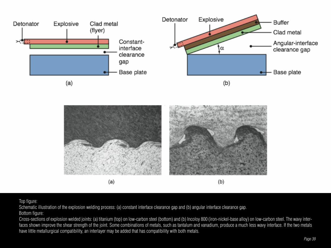
Top figure:Schematic illustration of the explosion welding process: (a) constant interface clearance gap and (b) angular interface clearance gap.Bottom figure:Cross-sections of explosion welded joints: (a) titanium (top) on low-carbon steel (bottom) and (b) Incoloy 800 (iron-nickel-base alloy) on low-carbon steel. The wavy inter-faces shown improve the shear strength of the joint. Some combinations of metals, such as tantalum and vanadium, produce a much less wavy interface. If the two metals have little metallurgical compatibility, an interlayer may be added that has compatibility with both metals.

DIFFUSION BONDING
Diffusion bonding, also called diffusion welding, is a solid-state joining process in which the strength of the joint results primarily from diffusion (movement of atoms across the interface) and, to a lesser extent, from some plastic deformation of the faying surfaces. This process requires temperatures of about 0.5Tm (where Tm is the melting point of the metal on the absolute scale) in order to have a sufficiently high diffusion rate between the parts to be joined. The bonded interface in DFW has es-sentially the same physical and mechanical properties as those of the base metal.
Page 40
In diffusion bonding, the two parts are usually heated in a furnace or by electrical resistance. The pressure required may be applied by (a) using dead weights, (b) a press, (c) using differential gas pressure, or (d) from the relative thermal expansion of the parts to be joined. The process is generally most suitable for dissimilar metal pairs, although it is also used for reactive metals, such as titanium, beryllium, zir-conium, and refractory metal alloys.

Page 41
Sequence of operations in diffusion bonding and superplastic forming of a structure with three flat sheets.

BRAZING
In brazing, a filler metal is placed at or between the faying surfaces to be joined, and the temperature is raised to melt the filler metal, but not the workpieces. The molten metal fills the closely fitting space by capillary action. Upon cooling and solidifica-tion of the filler metal, a strong joint is developed. This process is unlike liquid-state welding processes, in which the workpieces must melt in the weld area for fusion to occur. Any difficulties associated with heat-affected zones, warping, and residual stresses are, therefore, reduced in the brazing process. The strength of the brazed
Page 42
joint depends on joint design and the bond at the interfaces of the workpiece and filler metal. Consequently, the surfaces to be brazed should be chemically or me-chanically cleaned to ensure full capillary action; thus, the use of a flux is important. The clearance between the mating surfaces is an important parameter, as it directly affects the strength of the brazed joint. Note that the smaller the gap, the higher is the shear strength of the joint.

Page 43
(a) Brazing and (b) braze welding operations.

SOLDERING
In soldering, the filler metal (solder), fills the joint by capillary action between closely fitting or closely placed components. Heat sources for soldering are typically soldering irons, torches, or ovens. Soldering can be used to join various metals and part thicknesses and is used extensively in the electronics industry. Unlike in brazing, tempera-tures in soldering are relatively low; consequently, a soldered joint has very limited use at elevated temperatures. Moreover, because solders do not generally have much strength, they are not used for load-bearing structural members.
Page 44

Page 45
(a) Brazing and (b) braze welding operations.

ADHESIVEBONDING
Numerous components and products can be joined and assembled with an adhesive. Adhesive bonding has been a common method of joining and assembly for applica-tions such as bookbinding, labeling, packaging, home furnishings, and footwear. Numerous types of adhesives are available, and continue to be developed, that provide adequate joint strength, including fatigue strength and resistance to environmental attack.
Page 46

Page 47
Top figure:Various configurations for adhesively bonded joints: (a) single lap, (b) double lap, (c) scarf, and (d) strap.Bottom figure:Characteristic behavior of (a) brittle and (b) tough and ductile adhesives in a peeling test. This test is similar to peeling adhesive tape from a solid surface.

MECHANICALFASTENING
Countless products have components that are fastened mechanically, whereby two or more components are assembled in such a way that they can be taken apart dur-ing the product’s service life or life cycle. Mechanical fastening maybe be preferred over other methods because of its 1. Ease of manufacturing.2. Ease of assembly, disassembly, and transportation.
Page 48
3. Ease of parts replacement, maintenance, and repair.4. Ease in creating designs that require movable joints.5. Lower overall cost of manufacturing the product.

Page 49
Top left figure:Examples of rivets: (a) solid, (b) tubular, (c) split, or bifurcated, and (d) compression.Bottom left figure:Stages in forming a double-lock seamRight figure:Examples of spring and snap-in fasteners to facilitate assembly.

REFERENCES
Page 50
- S. Kalpakjian, S. R. S. (2003). Manufacturing Engineering and Technology. New Jersey, Pearson Prentice Hall.- Groover, M. P. (2010). Principles of Modern Manufacturing: Materials, Processes, and Systems, John Wiley & Sons Ltd.
Recommended