Sound Insulation
J. NEGREIRA, D. BARD
DIVISION OF ENGINEERING ACOUSTICS, LUND UNIVERSITY
J. Negreira / Acoustics VTAF05 / 24-Nov-15
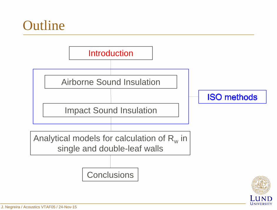
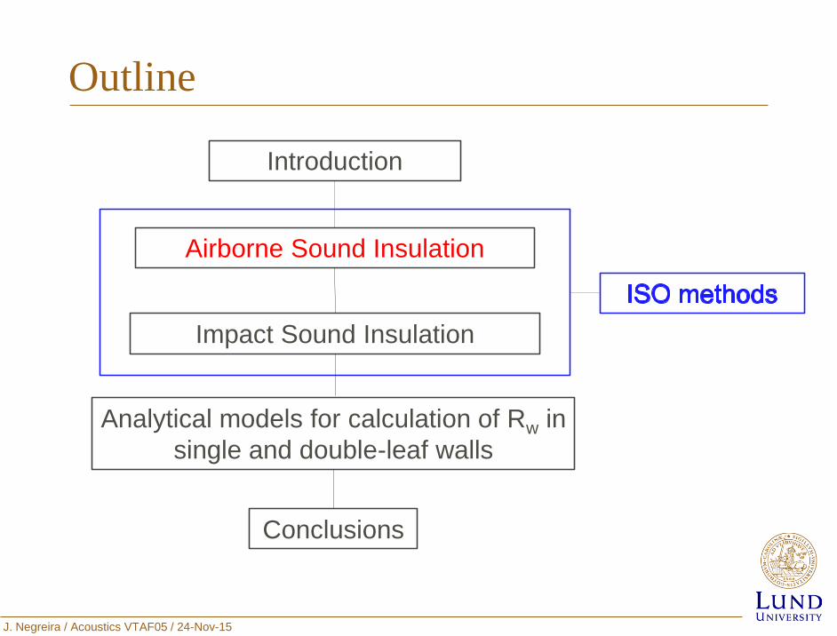
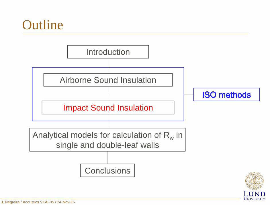
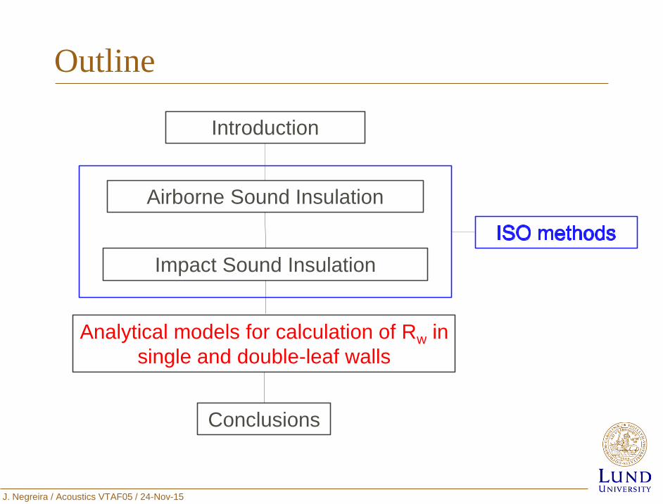
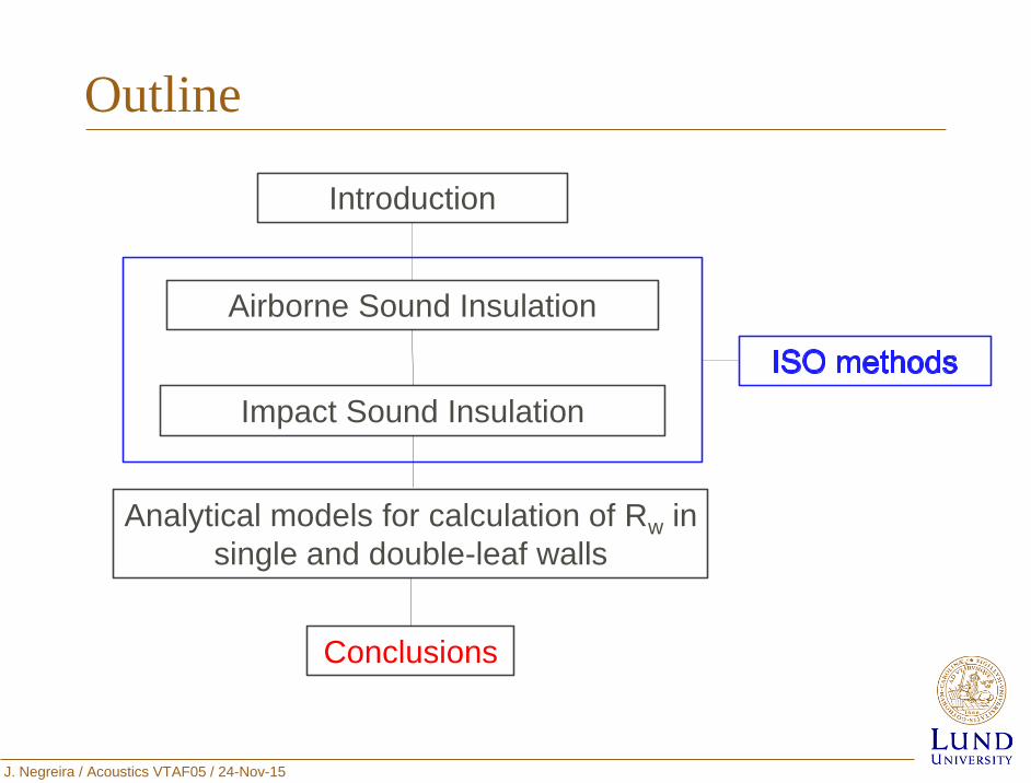
Outline
Introduction
Airborne Sound Insulation
Impact Sound Insulation
Conclusions
Analytical models for calculation of Rw in
single and double-leaf walls
J. Negreira / Acoustics VTAF05 / 24-Nov-15
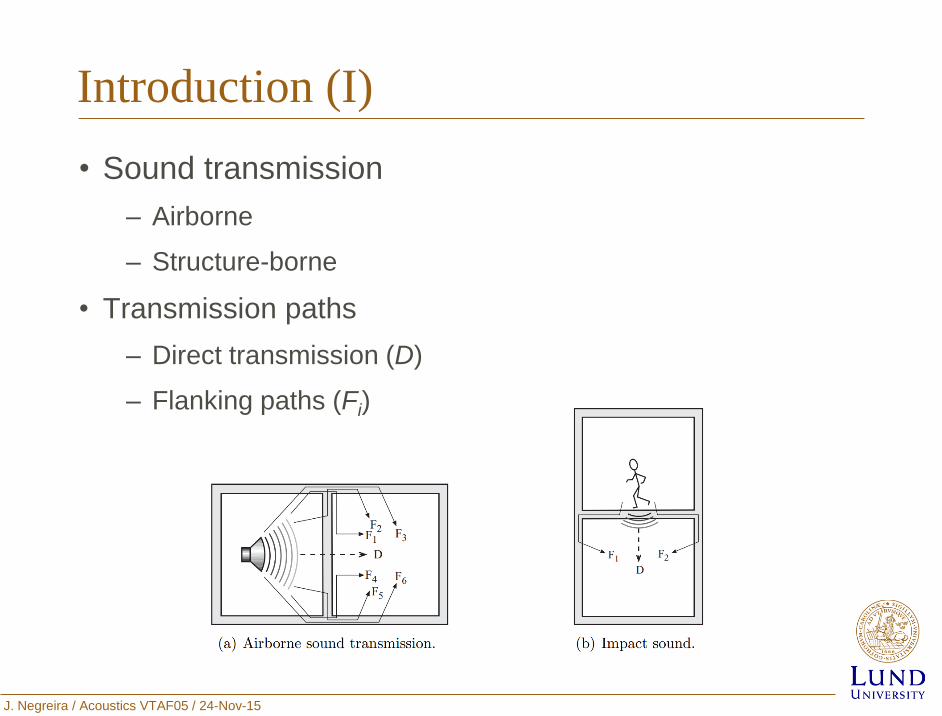
Introduction (I)
• Sound transmission
– Airborne
– Structure-borne
• Transmission paths
– Direct transmission (D)
– Flanking paths (Fi)
J. Negreira / Acoustics VTAF05 / 24-Nov-15
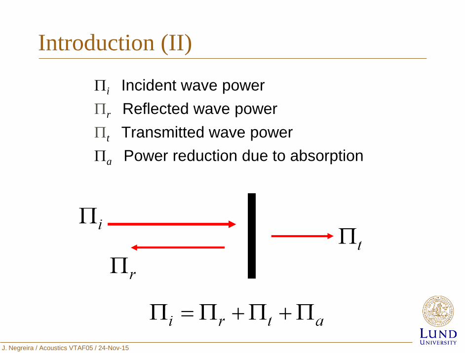
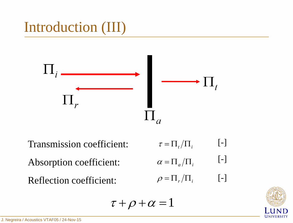
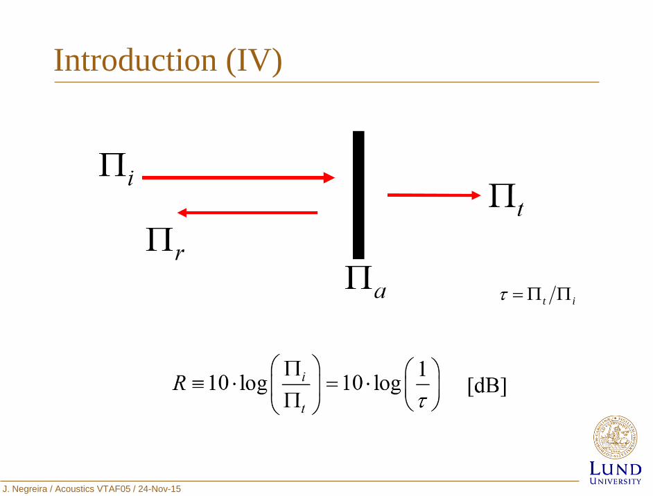
i Incident wave power
r Reflected wave power
t Transmitted wave power
a Power reduction due to absorption
Introduction (II)
J. Negreira / Acoustics VTAF05 / 24-Nov-15
Introduction (III)
Transmission coefficient:
Absorption coefficient:
Reflection coefficient:
[-]
ia
it
[-]
[-]
ir
1
J. Negreira / Acoustics VTAF05 / 24-Nov-15
Introduction (IV)
it
J. Negreira / Acoustics VTAF05 / 24-Nov-15
Outline
Introduction
Airborne Sound Insulation
Impact Sound Insulation
Conclusions
Analytical models for calculation of Rw in
single and double-leaf walls
J. Negreira / Acoustics VTAF05 / 24-Nov-15
References
• ISO 140, Acoustics – Measurement of sound insulation in buildings
and of building elements – Part 3: Laboratory measurements of
airborne sound insulation of building elements (1995).
• ISO 140, Acoustics – Measurement of sound insulation in buildings
and of building elements – Part 4: Field measurements of airborne
sound insulation between rooms (1998).
• ISO 140, Acoustics – Measurement of sound insulation in buildings
and of building elements – Part 5: Field measurements of airborne
sound insulation of facade – elements and facades (1998).
• ISO 140, Acoustics – Measurement of sound insulation in buildings
and of building elements – Part 10: Laboratory measurements of
airborne sound insulation of small building elements (1991)
• ISO 717, Acoustics - Rating of sound insulation in buildings and of
buildings elements – Part 1: Airborne sound insulation (1996).
J. Negreira / Acoustics VTAF05 / 24-Nov-15
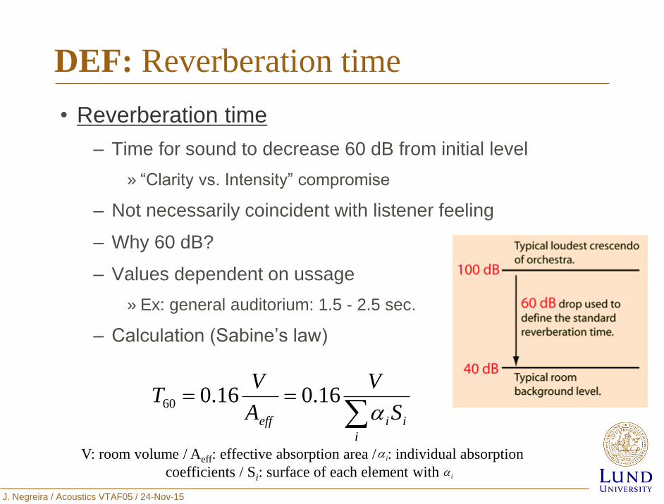
DEF: Reverberation time
• Reverberation time
– Time for sound to decrease 60 dB from initial level
» “Clarity vs. Intensity” compromise
– Not necessarily coincident with listener feeling
– Why 60 dB?
– Values dependent on ussage
» Ex: general auditorium: 1.5 - 2.5 sec.
– Calculation (Sabine’s law)
i
iieff S
V
A
VT
16.016.060
V: room volume / Aeff: effective absorption area / : individual absorption
coefficients / Si: surface of each element with i
i
J. Negreira / Acoustics VTAF05 / 24-Nov-15
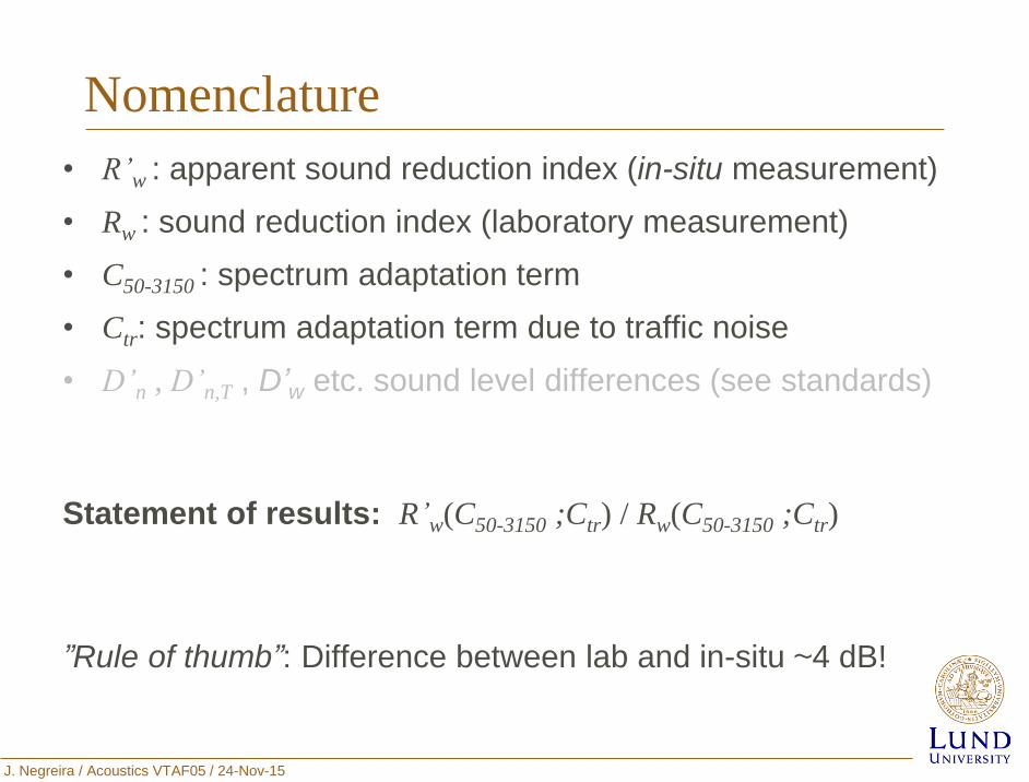
Nomenclature
• R’w : apparent sound reduction index (in-situ measurement)
• Rw : sound reduction index (laboratory measurement)
• C50-3150 : spectrum adaptation term
• Ctr: spectrum adaptation term due to traffic noise
• D’n , D’n,T , D’w etc. sound level differences (see standards)
Statement of results: R’w(C50-3150 ;Ctr) / Rw(C50-3150 ;Ctr)
”Rule of thumb”: Difference between lab and in-situ ~4 dB!
J. Negreira / Acoustics VTAF05 / 24-Nov-15
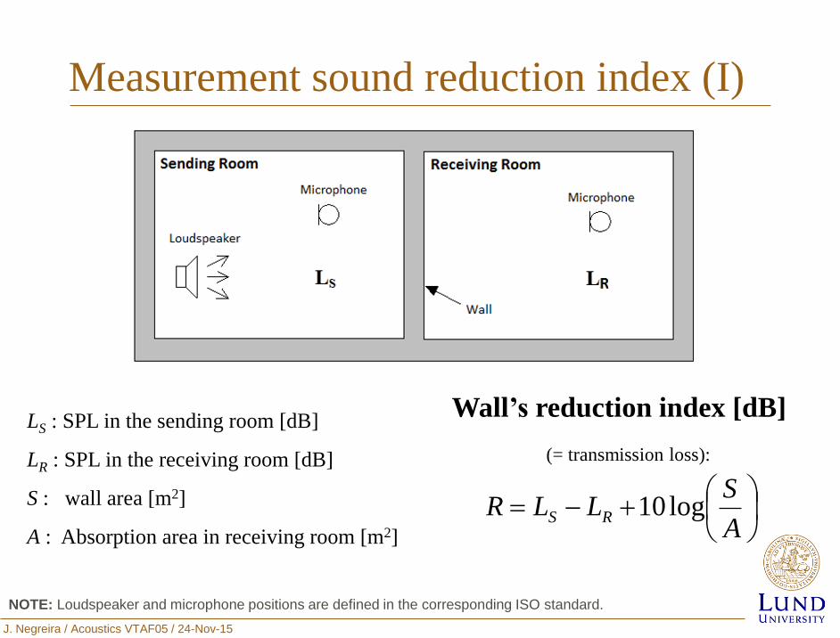
Measurement sound reduction index (I)
LS : SPL in the sending room [dB]
LR : SPL in the receiving room [dB]
S : wall area [m2]
A : Absorption area in receiving room [m2]
Wall’s reduction index [dB]
(= transmission loss):
A
SLLR RS log10
NOTE: Loudspeaker and microphone positions are defined in the corresponding ISO standard.
J. Negreira / Acoustics VTAF05 / 24-Nov-15
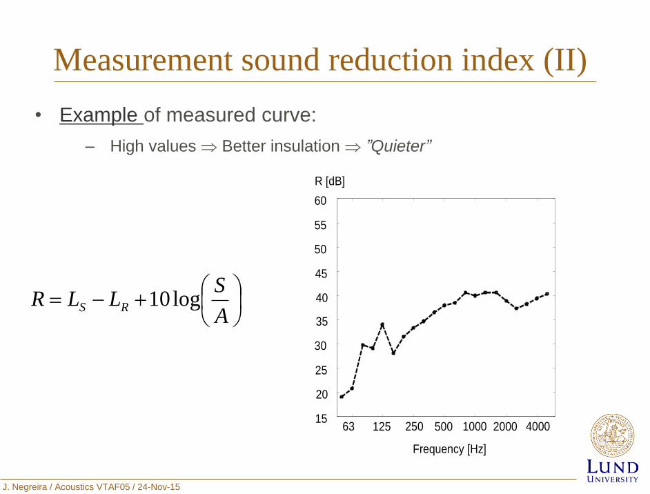
Measurement sound reduction index (II)
• Example of measured curve:
‒ High values Better insulation ”Quieter”
63 125 250 500 1000 2000 4000 15
20
25
30
35
40
45
50
55
60
Frequency [Hz]
R [dB]
A
SLLR RS log10
J. Negreira / Acoustics VTAF05 / 24-Nov-15
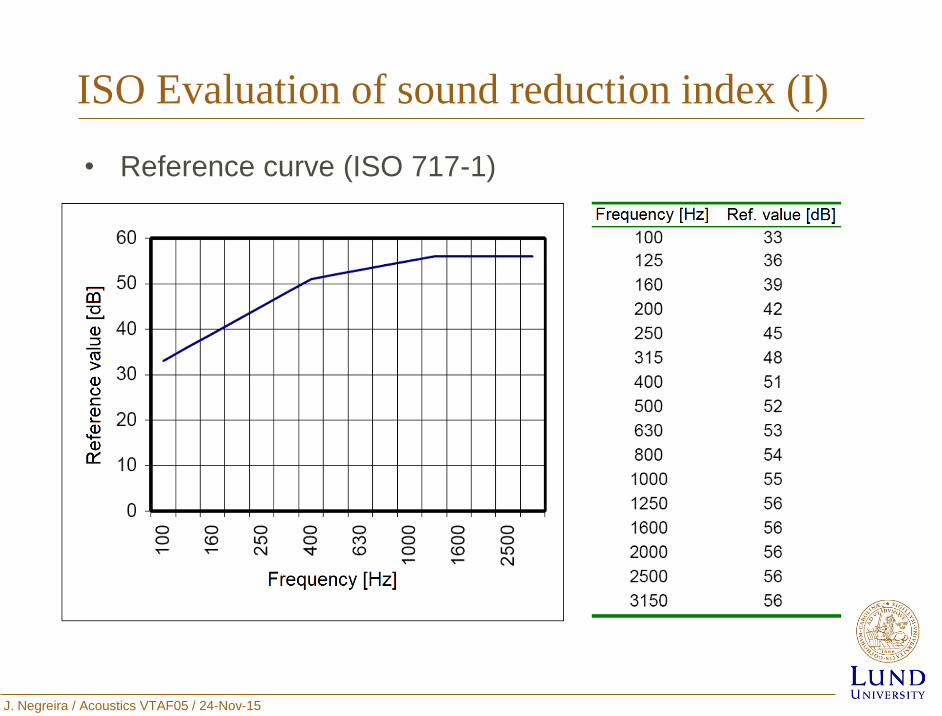
ISO Evaluation of sound reduction index (I)
• Reference curve (ISO 717-1)
J. Negreira / Acoustics VTAF05 / 24-Nov-15
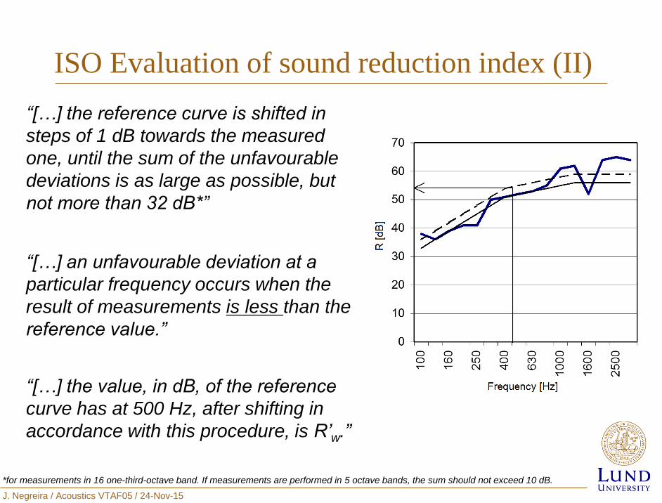
ISO Evaluation of sound reduction index (II)
“[…] the reference curve is shifted in
steps of 1 dB towards the measured
one, until the sum of the unfavourable
deviations is as large as possible, but
not more than 32 dB*”
“[…] an unfavourable deviation at a
particular frequency occurs when the
result of measurements is less than the
reference value.”
“[…] the value, in dB, of the reference
curve has at 500 Hz, after shifting in
accordance with this procedure, is R’w.”
*for measurements in 16 one-third-octave band. If measurements are performed in 5 octave bands, the sum should not exceed 10 dB.
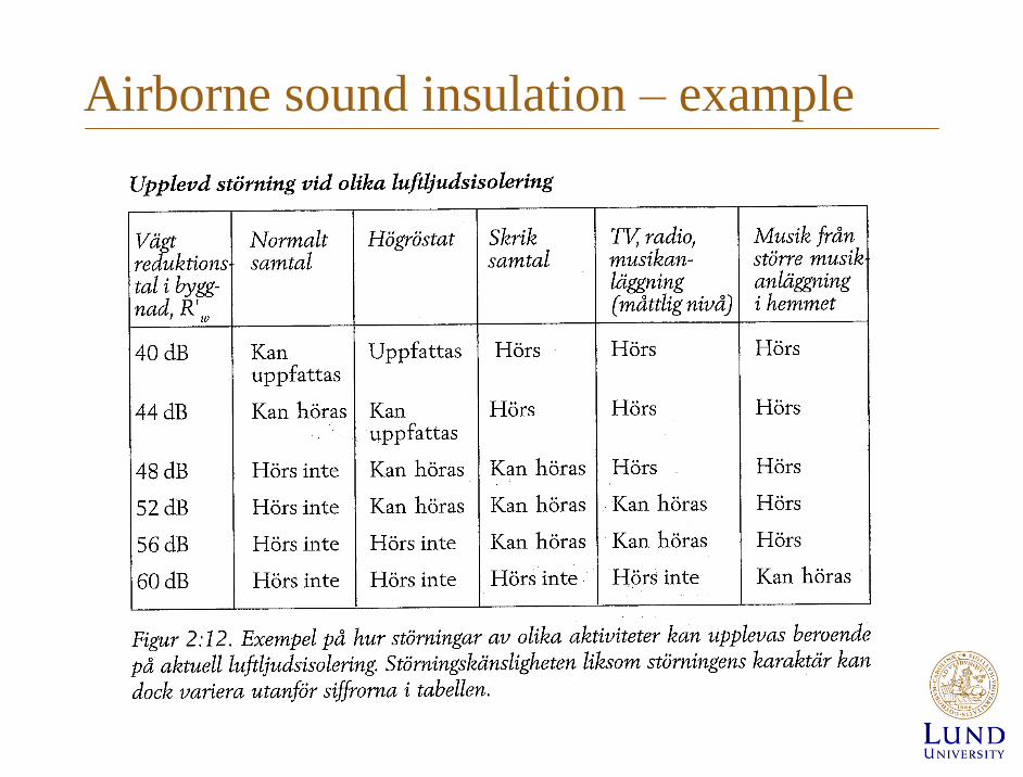
Airborne sound insulation – example
J. Negreira / Acoustics VTAF05 / 24-Nov-15
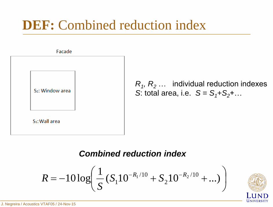
DEF: Combined reduction index
...)1010(
1log10
10/
2
10/
121 RR
SSS
R
R1, R2 … individual reduction indexes
S: total area, i.e. S = S1+S2+…
Combined reduction index
J. Negreira / Acoustics VTAF05 / 24-Nov-15
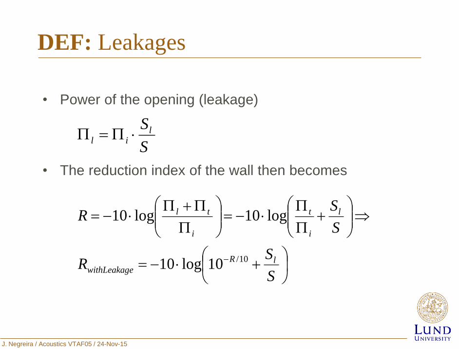
DEF: Leakages
• Power of the opening (leakage)
• The reduction index of the wall then becomes
S
Slil
S
SR
S
SR
lR
ewithLeakag
l
i
t
i
tl
10/10log10
log10log10
J. Negreira / Acoustics VTAF05 / 24-Nov-15
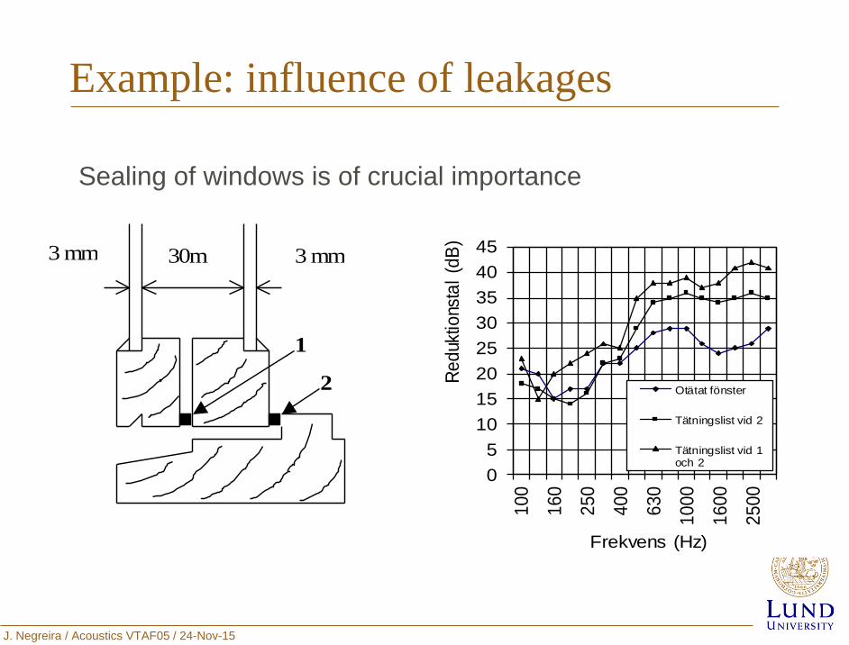
Example: influence of leakages
Sealing of windows is of crucial importance
3 mm
1
2
30m
m
3 mm
0
5
10
15
20
25
30
35
40
45
10
0
16
0
25
0
40
0
63
0
10
00
16
00
25
00
Re
duk
tions
tal
(dB
)
Frekvens (Hz)
Otätat fönster
Tätningslist vid 2
Tätningslist vid 1och 2
J. Negreira / Acoustics VTAF05 / 24-Nov-15
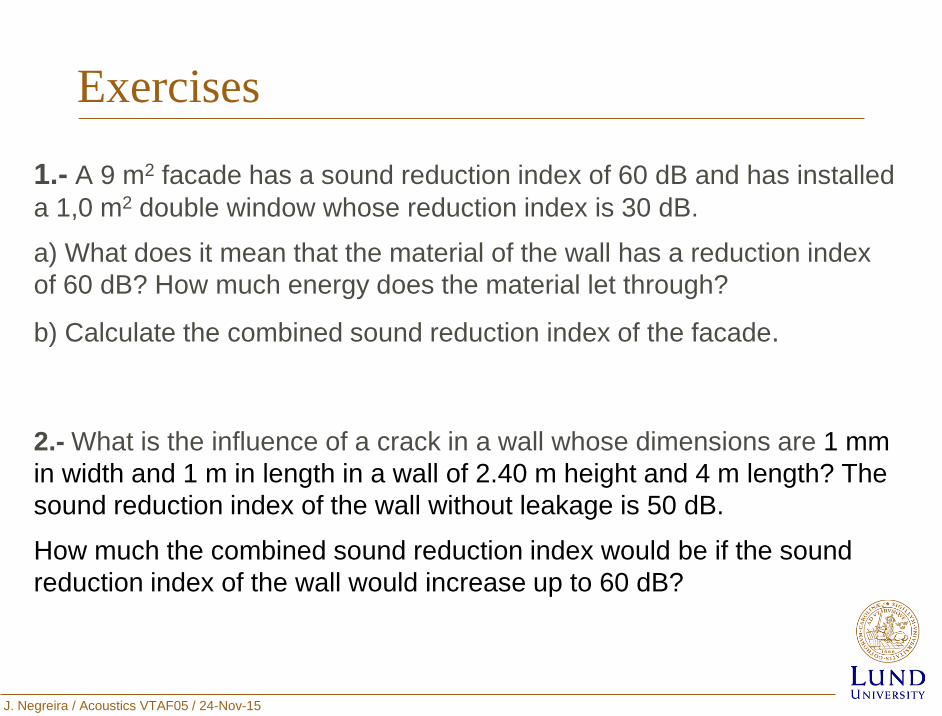
Exercises
2.- What is the influence of a crack in a wall whose dimensions are 1 mm
in width and 1 m in length in a wall of 2.40 m height and 4 m length? The
sound reduction index of the wall without leakage is 50 dB.
How much the combined sound reduction index would be if the sound
reduction index of the wall would increase up to 60 dB?
1.- A 9 m2 facade has a sound reduction index of 60 dB and has installed
a 1,0 m2 double window whose reduction index is 30 dB.
a) What does it mean that the material of the wall has a reduction index
of 60 dB? How much energy does the material let through?
b) Calculate the combined sound reduction index of the facade.
J. Negreira / Acoustics VTAF05 / 24-Nov-15
Outline
Introduction
Airborne Sound Insulation
Impact Sound Insulation
Conclusions
Analytical models for calculation of Rw in
single and double-leaf walls
J. Negreira / Acoustics VTAF05 / 24-Nov-15
References
• ISO 140, Acoustics – Measurement of sound insulation in buildings
and of building elements – Part 6: Laboratory measurements of
impact sound insulation of floors (1998).
• ISO 140, Acoustics – Measurement of sound insulation in buildings
and of building elements – Part 7: Field measurements of impact
sound insulation of building elements (1998).
• ISO 717, Acoustics - Rating of sound insulation in buildings and of
buildings elements – Part 2: Impact sound insulation (1996).
J. Negreira / Acoustics VTAF05 / 24-Nov-15
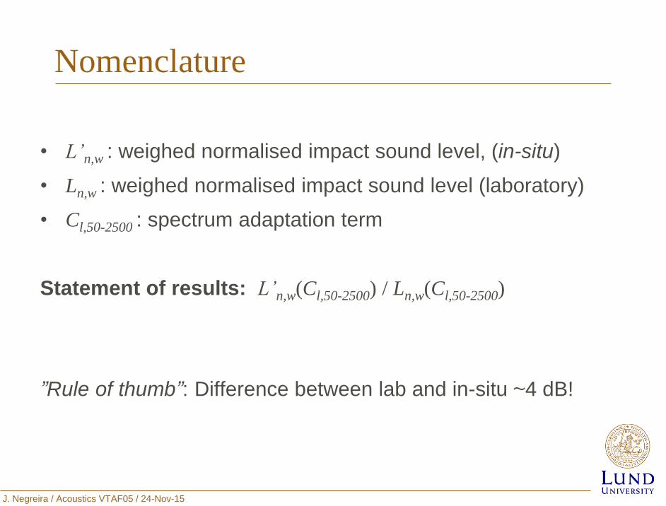
Nomenclature
• L’n,w : weighed normalised impact sound level, (in-situ)
• Ln,w : weighed normalised impact sound level (laboratory)
• Cl,50-2500 : spectrum adaptation term
Statement of results: L’n,w(Cl,50-2500) / Ln,w(Cl,50-2500)
”Rule of thumb”: Difference between lab and in-situ ~4 dB!
J. Negreira / Acoustics VTAF05 / 24-Nov-15
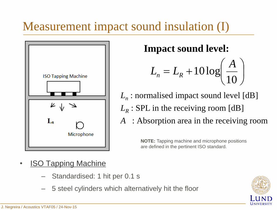
Measurement impact sound insulation (I)
Ln : normalised impact sound level [dB]
LR : SPL in the receiving room [dB]
A : Absorption area in the receiving room
10log10
ALL Rn
Impact sound level:
• ISO Tapping Machine
‒ Standardised: 1 hit per 0.1 s
‒ 5 steel cylinders which alternatively hit the floor
NOTE: Tapping machine and microphone positions
are defined in the pertinent ISO standard.
J. Negreira / Acoustics VTAF05 / 24-Nov-15
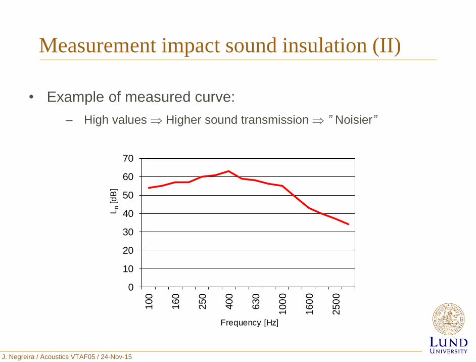
Measurement impact sound insulation (II)
• Example of measured curve:
‒ High values Higher sound transmission ” Noisier”
0
10
20
30
40
50
60
70100
160
250
400
630
100
0
160
0
250
0
Ln
[dB
]
Frequency [Hz]
J. Negreira / Acoustics VTAF05 / 24-Nov-15
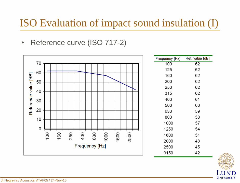
ISO Evaluation of impact sound insulation (I)
• Reference curve (ISO 717-2)
J. Negreira / Acoustics VTAF05 / 24-Nov-15
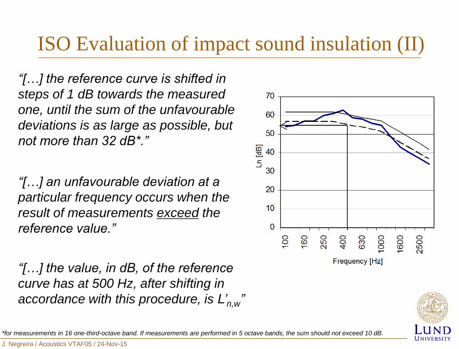
ISO Evaluation of impact sound insulation (II)
“[…] the reference curve is shifted in
steps of 1 dB towards the measured
one, until the sum of the unfavourable
deviations is as large as possible, but
not more than 32 dB*.”
“[…] an unfavourable deviation at a
particular frequency occurs when the
result of measurements exceed the
reference value.”
“[…] the value, in dB, of the reference
curve has at 500 Hz, after shifting in
accordance with this procedure, is L’n,w”
*for measurements in 16 one-third-octave band. If measurements are performed in 5 octave bands, the sum should not exceed 10 dB.
J. Negreira / Acoustics VTAF05 / 24-Nov-15
Sound classes (Sweden)
• Ljudklass A: the soundclass corresponds to very good
acoustic conditions.
• Ljudklass B: it comprises slightly better acoustic conditions
than soundclass C. Certain individuals can still, in some
cases, be disturbed. This sound class are the minimum
requirements if good living environment is requested.
• Ljudklass C: this is the minimum requirements in Swedish
buildings.
• Ljudklass D: Sound class corresponds noise conditions that
are intended to be applied when sound class C cannot be
achieved, e.g. in connection with the refurbishment.
J. Negreira / Acoustics VTAF05 / 24-Nov-15
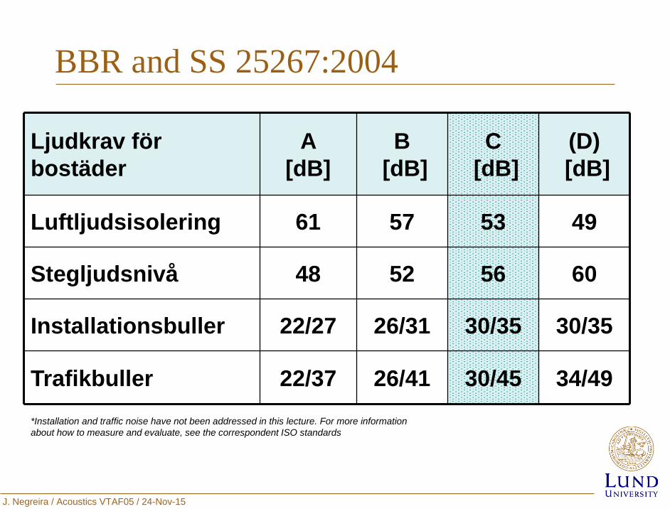
BBR and SS 25267:2004
Ljudkrav för
bostäder
A
[dB]
B
[dB]
C
[dB]
(D)
[dB]
Luftljudsisolering 61 57 53 49
Stegljudsnivå 48 52 56 60
Installationsbuller 22/27 26/31 30/35 30/35
Trafikbuller 22/37 26/41 30/45 34/49
*Installation and traffic noise have not been addressed in this lecture. For more information
about how to measure and evaluate, see the correspondent ISO standards
J. Negreira / Acoustics VTAF05 / 24-Nov-15
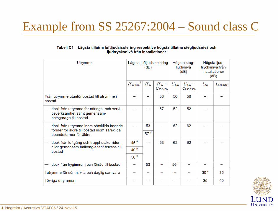
Example from SS 25267:2004 – Sound class C
J. Negreira / Acoustics VTAF05 / 24-Nov-15
Outline
Introduction
Airborne Sound Insulation
Impact Sound Insulation
Conclusions
Analytical models for calculation of Rw in
single and double-leaf walls
J. Negreira / Acoustics VTAF05 / 24-Nov-15
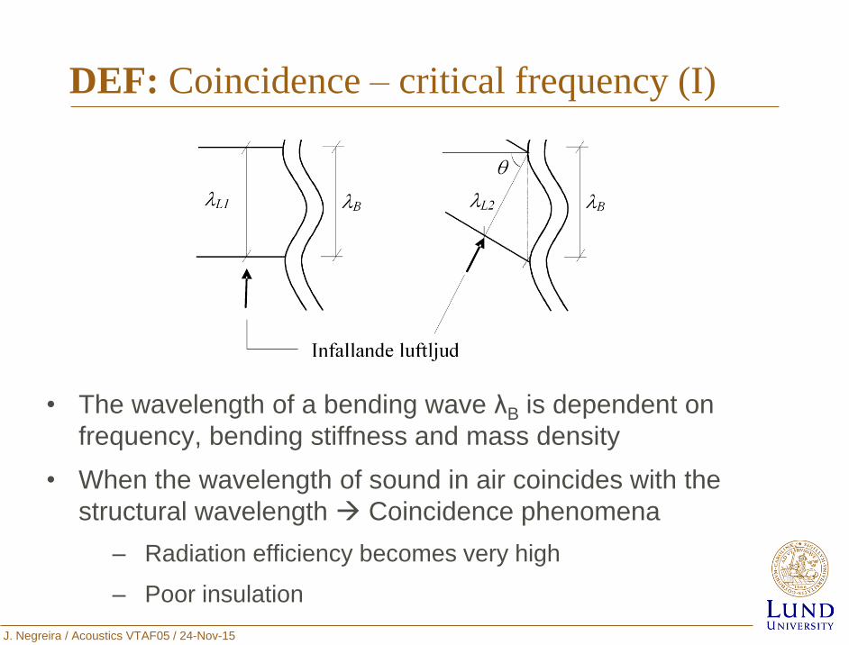
DEF: Coincidence – critical frequency (I)
• The wavelength of a bending wave λB is dependent on
frequency, bending stiffness and mass density
• When the wavelength of sound in air coincides with the
structural wavelength Coincidence phenomena
‒ Radiation efficiency becomes very high
‒ Poor insulation
J. Negreira / Acoustics VTAF05 / 24-Nov-15
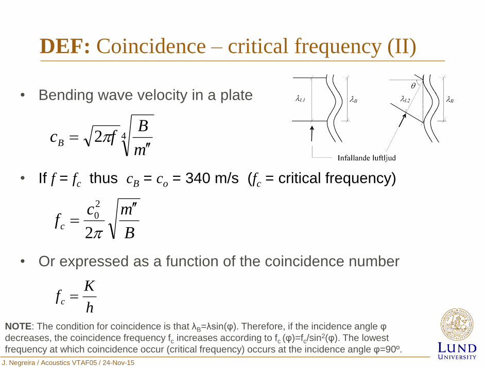
DEF: Coincidence – critical frequency (II)
• Bending wave velocity in a plate
• If f = fc thus cB = co = 340 m/s (fc = critical frequency)
• Or expressed as a function of the coincidence number
42m
BfcB
B
mcfc
2
2
0
h
Kfc
NOTE: The condition for coincidence is that λB=λsin(φ). Therefore, if the incidence angle φ
decreases, the coincidence frequency fc increases according to fc (φ)=fc/sin2(φ). The lowest
frequency at which coincidence occur (critical frequency) occurs at the incidence angle φ=90º.
J. Negreira / Acoustics VTAF05 / 24-Nov-15
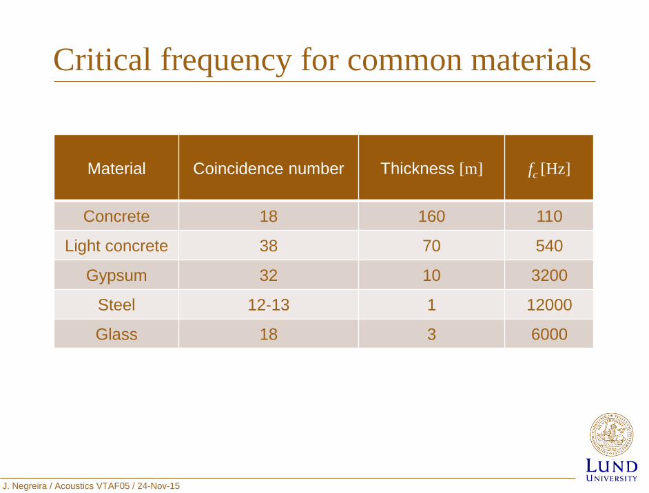
Critical frequency for common materials
Material Coincidence number Thickness [m] fc [Hz]
Concrete 18 160 110
Light concrete 38 70 540
Gypsum 32 10 3200
Steel 12-13 1 12000
Glass 18 3 6000
J. Negreira / Acoustics VTAF05 / 24-Nov-15
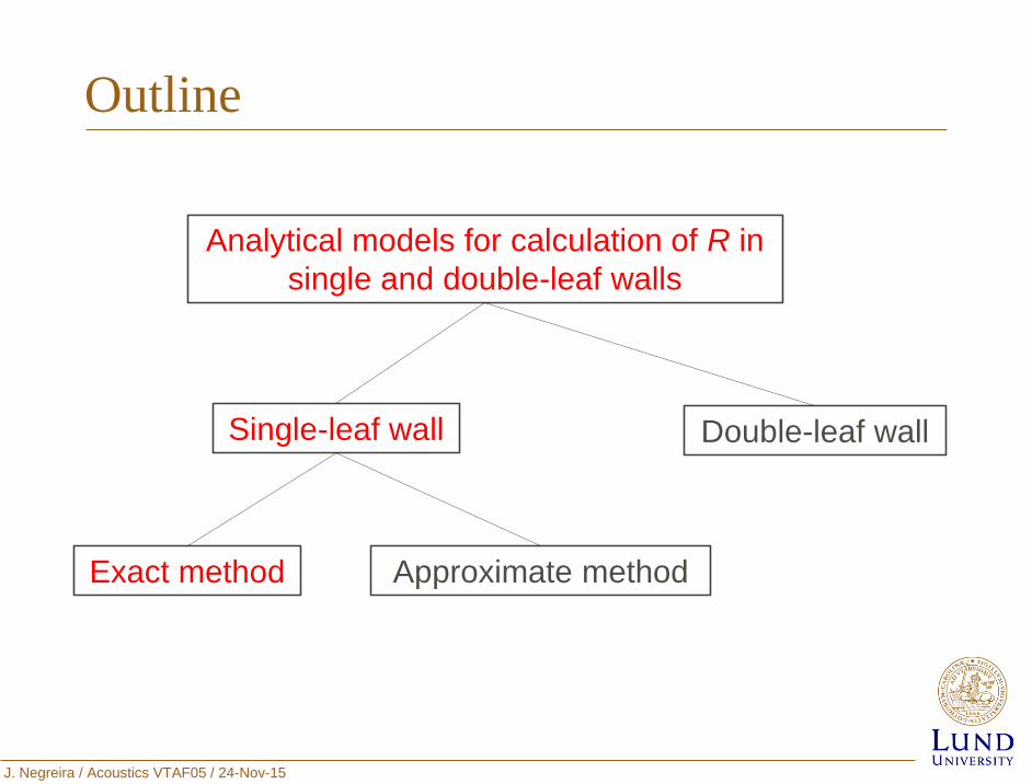
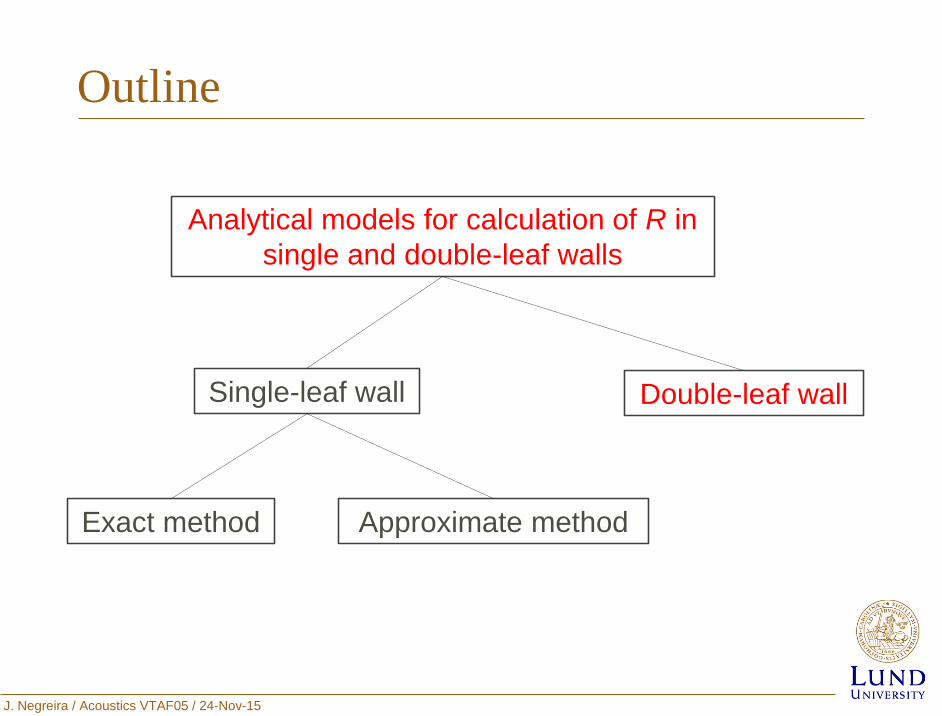
Outline
Double-leaf wall
Exact method
Analytical models for calculation of R in
single and double-leaf walls
Single-leaf wall
Approximate method
J. Negreira / Acoustics VTAF05 / 24-Nov-15
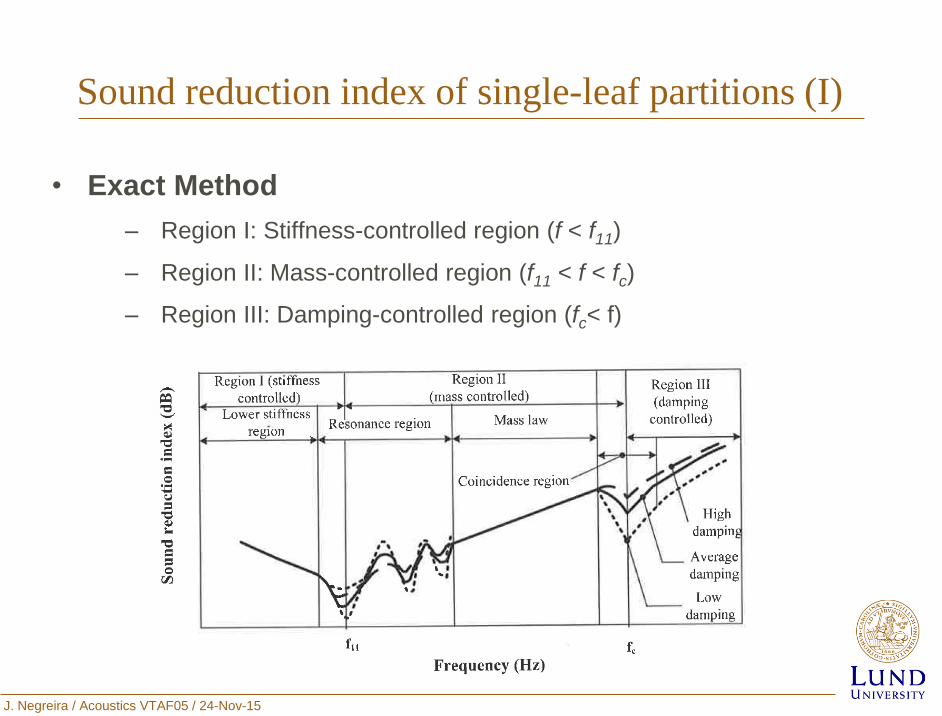
Sound reduction index of single-leaf partitions (I)
• Exact Method
‒ Region I: Stiffness-controlled region (f < f11)
‒ Region II: Mass-controlled region (f11 < f < fc)
‒ Region III: Damping-controlled region (fc< f)
J. Negreira / Acoustics VTAF05 / 24-Nov-15
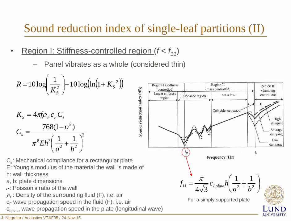
Sound reduction index of single-leaf partitions (II)
• Region I: Stiffness-controlled region (f < f11)
‒ Panel vibrates as a whole (considered thin)
2
22
38
2
2
2
11
)1(768
4
1lnlog101
log10
baEh
C
CcfK
KK
R
s
sFFS
S
S
Cs: Mechanical compliance for a rectangular plate
E: Young’s modulus of the material the wall is made of
h: wall thickness
a, b: plate dimensions
: Poisson’s ratio of the wall
: Density of the surrounding fluid (F), i.e. air
cF wave propagation speed in the fluid (F), i.e. air
cLplate wave propagation speed in the plate (longitudinal wave)
F
2211
11
34 bahcf Lplate
For a simply supported plate
J. Negreira / Acoustics VTAF05 / 24-Nov-15
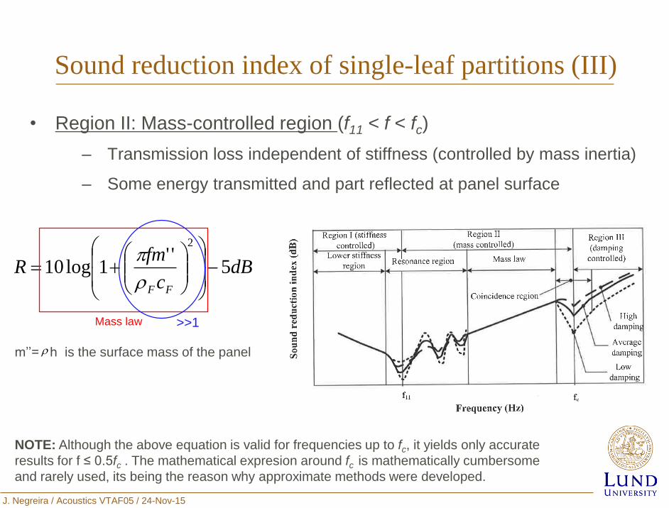
Sound reduction index of single-leaf partitions (III)
• Region II: Mass-controlled region (f11 < f < fc)
‒ Transmission loss independent of stiffness (controlled by mass inertia)
‒ Some energy transmitted and part reflected at panel surface
dBc
fmR
FF
5''
1log10
2
m’’= h is the surface mass of the panel
NOTE: Although the above equation is valid for frequencies up to fc, it yields only accurate
results for f ≤ 0.5fc . The mathematical expresion around fc is mathematically cumbersome
and rarely used, its being the reason why approximate methods were developed.
Mass law >>1
J. Negreira / Acoustics VTAF05 / 24-Nov-15
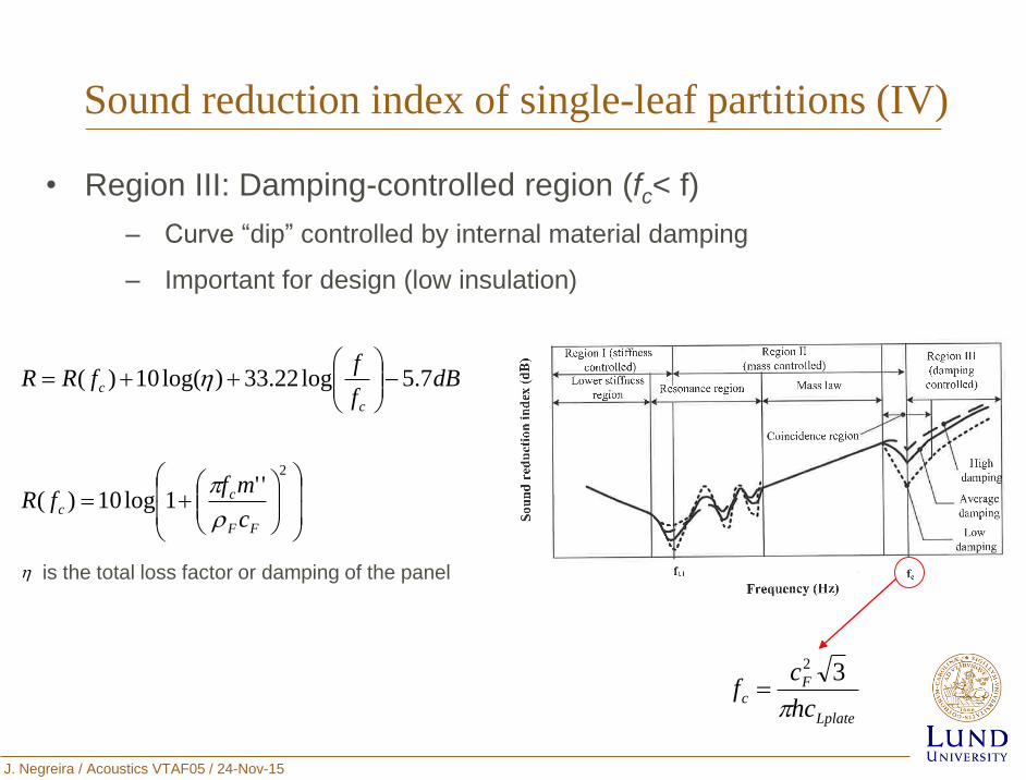
Sound reduction index of single-leaf partitions (IV)
• Region III: Damping-controlled region (fc< f)
‒ Curve “dip” controlled by internal material damping
‒ Important for design (low insulation)
2
''1log10)(
7.5log22.33)log(10)(
FF
cc
c
c
c
mffR
dBf
ffRR
is the total loss factor or damping of the panel
Lplate
Fc
hc
cf
32
J. Negreira / Acoustics VTAF05 / 24-Nov-15
Outline
Double-leaf wall
Exact method
Analytical models for calculation of R in
single and double-leaf walls
Single-leaf wall
Approximate method
J. Negreira / Acoustics VTAF05 / 24-Nov-15
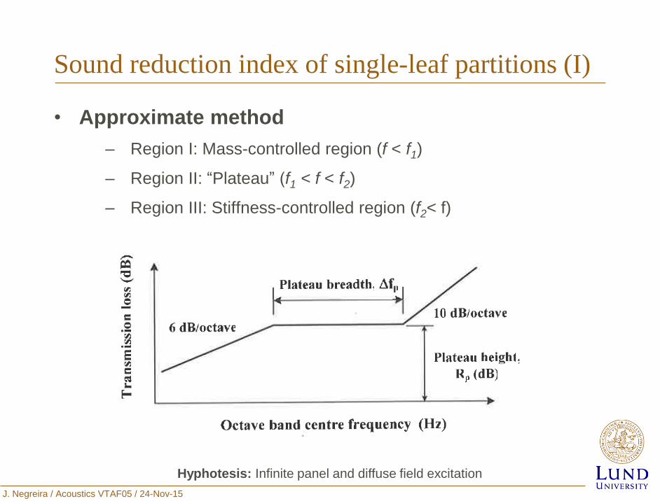
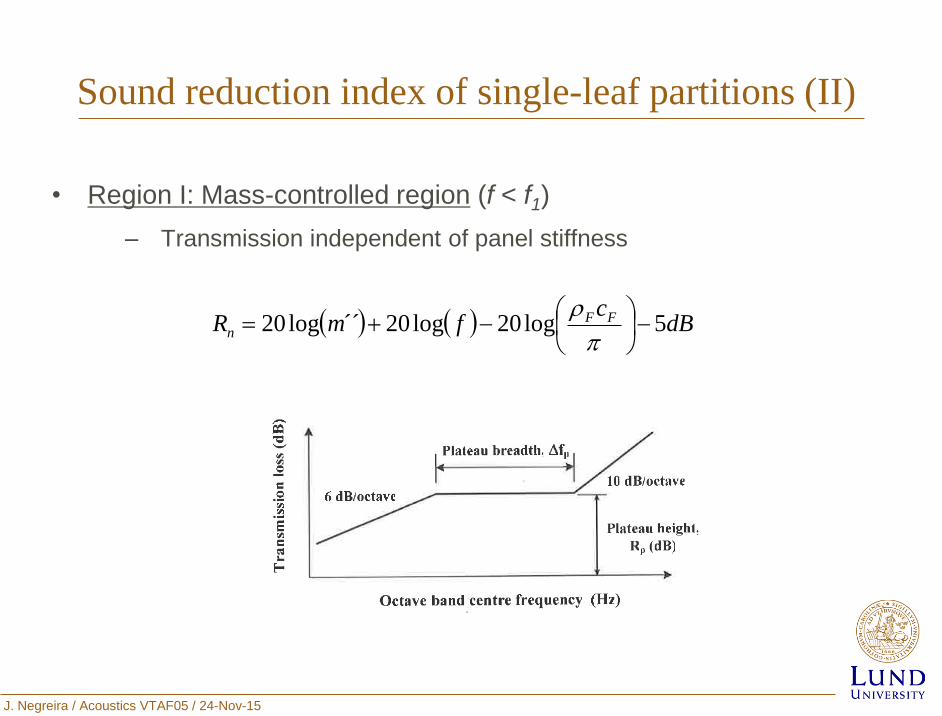
Sound reduction index of single-leaf partitions (I)
• Approximate method
‒ Region I: Mass-controlled region (f < f1)
‒ Region II: “Plateau” (f1 < f < f2)
‒ Region III: Stiffness-controlled region (f2< f)
Hyphotesis: Infinite panel and diffuse field excitation
J. Negreira / Acoustics VTAF05 / 24-Nov-15
Sound reduction index of single-leaf partitions (II)
• Region I: Mass-controlled region (f < f1)
‒ Transmission independent of panel stiffness
dBc
fmR FFn 5log20log20´´log20
J. Negreira / Acoustics VTAF05 / 24-Nov-15
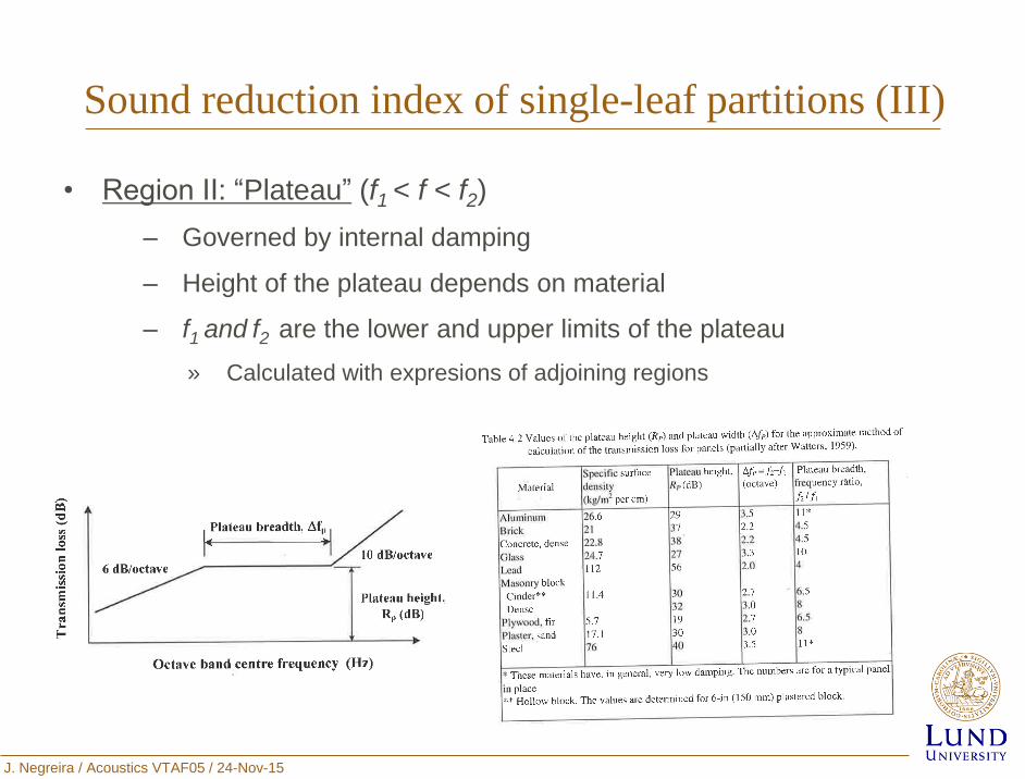
Sound reduction index of single-leaf partitions (III)
• Region II: “Plateau” (f1 < f < f2)
‒ Governed by internal damping
‒ Height of the plateau depends on material
‒ f1 and f2 are the lower and upper limits of the plateau
» Calculated with expresions of adjoining regions
J. Negreira / Acoustics VTAF05 / 24-Nov-15
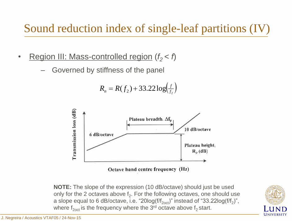
Sound reduction index of single-leaf partitions (IV)
• Region III: Mass-controlled region (f2 < f)
‒ Governed by stiffness of the panel
2
log22.33)( 2 f
f
n fRR
NOTE: The slope of the expression (10 dB/octave) should just be used
only for the 2 octaves above f2. For the following octaves, one should use
a slope equal to 6 dB/octave, i.e. “20log(f/f2oct)” instead of “33.22log(f/f2)”,
where f2oct is the frequency where the 3rd octave above f2 start.
J. Negreira / Acoustics VTAF05 / 24-Nov-15
Outline
Double-leaf wall
Exact method
Analytical models for calculation of R in
single and double-leaf walls
Single-leaf wall
Approximate method
J. Negreira / Acoustics VTAF05 / 24-Nov-15
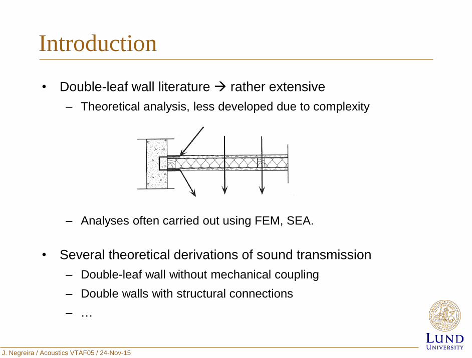
Introduction
• Double-leaf wall literature rather extensive
– Theoretical analysis, less developed due to complexity
– Analyses often carried out using FEM, SEA.
• Several theoretical derivations of sound transmission
– Double-leaf wall without mechanical coupling
– Double walls with structural connections
– …
J. Negreira / Acoustics VTAF05 / 24-Nov-15
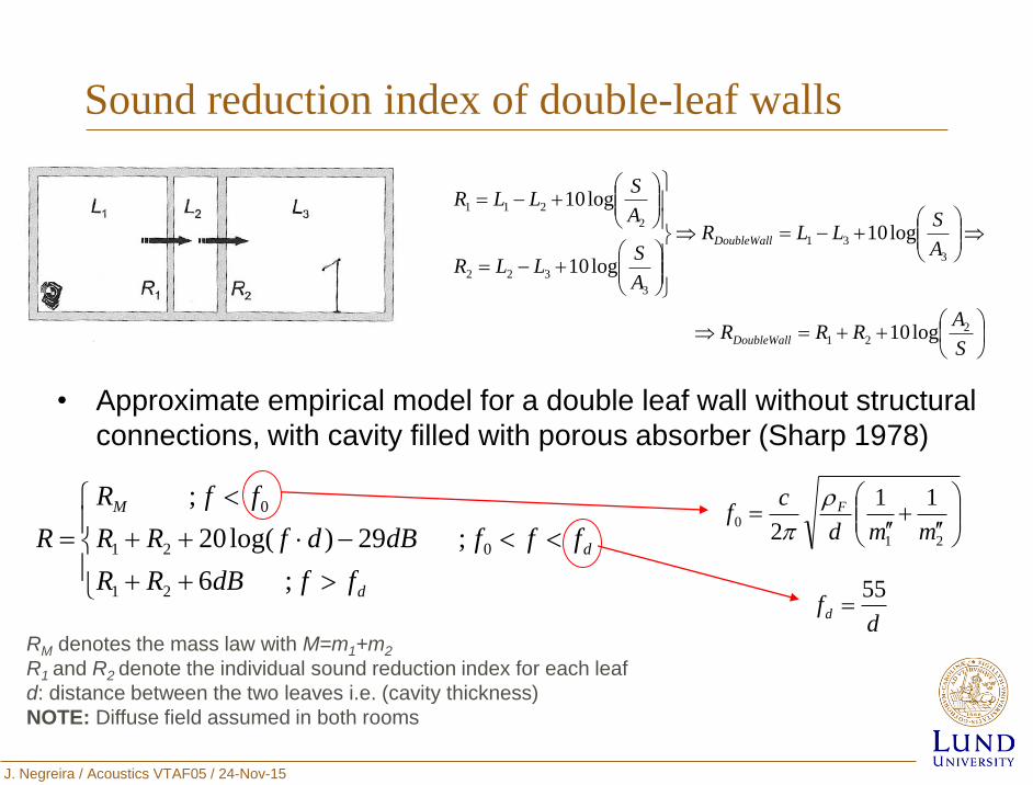
Sound reduction index of double-leaf walls
• Approximate empirical model for a double leaf wall without structural
connections, with cavity filled with porous absorber (Sharp 1978)
S
ARRR
A
SLLR
A
SLLR
A
SLLR
DoubleWall
DoubleWall
221
3
31
3
322
2
211
log10
log10
log10
log10
d
d
M
ffdBRR
fffdBdfRR
ffR
R
;6
;29)log(20
;
21
021
0
21
0
11
2 mmd
cf F
dfd
55
RM denotes the mass law with M=m1+m2
R1 and R2 denote the individual sound reduction index for each leaf
d: distance between the two leaves i.e. (cavity thickness)
NOTE: Diffuse field assumed in both rooms
J. Negreira / Acoustics VTAF05 / 24-Nov-15
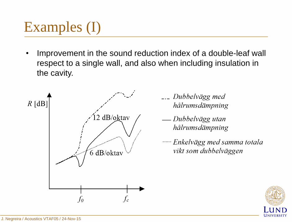
• Improvement in the sound reduction index of a double-leaf wall
respect to a single wall, and also when including insulation in
the cavity.
Examples (I)
J. Negreira / Acoustics VTAF05 / 24-Nov-15
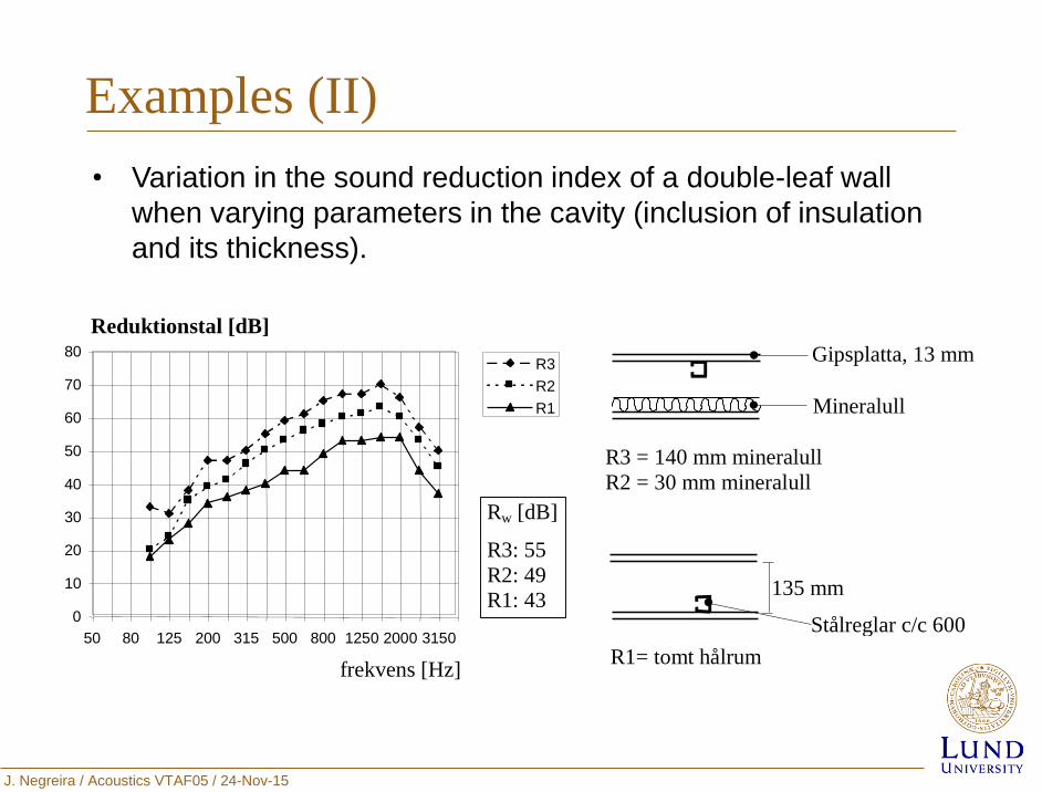
Examples (II)
0
10
20
30
40
50
60
70
80
50 80 125 200 315 500 800 1250 2000 3150
frekvens [Hz]
Reduktionstal [dB]
R3 R2 R1
135 mm
Gipsplatta, 13 mm
Mineralull
Stålreglar c/c 600
mm R1= tomt hålrum
R3 = 140 mm mineralull
R2 = 30 mm mineralull
Rw [dB]
R3: 55
R2: 49
R1: 43
• Variation in the sound reduction index of a double-leaf wall
when varying parameters in the cavity (inclusion of insulation
and its thickness).
J. Negreira / Acoustics VTAF05 / 24-Nov-15
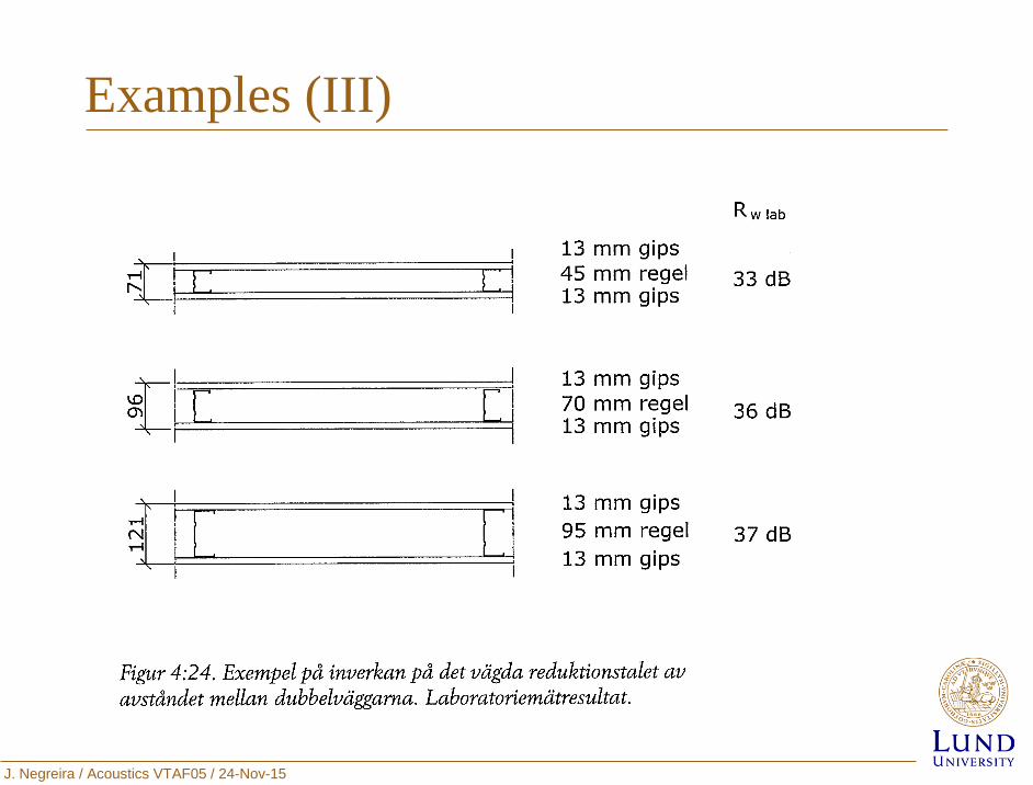
Examples (III)
J. Negreira / Acoustics VTAF05 / 24-Nov-15
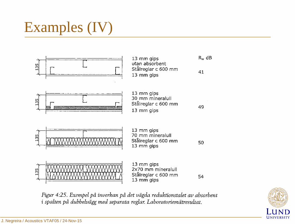
Examples (IV)
J. Negreira / Acoustics VTAF05 / 24-Nov-15
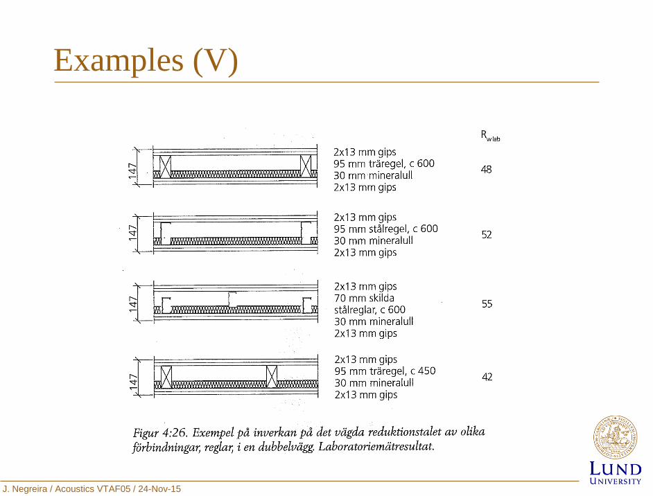
Examples (V)
J. Negreira / Acoustics VTAF05 / 24-Nov-15
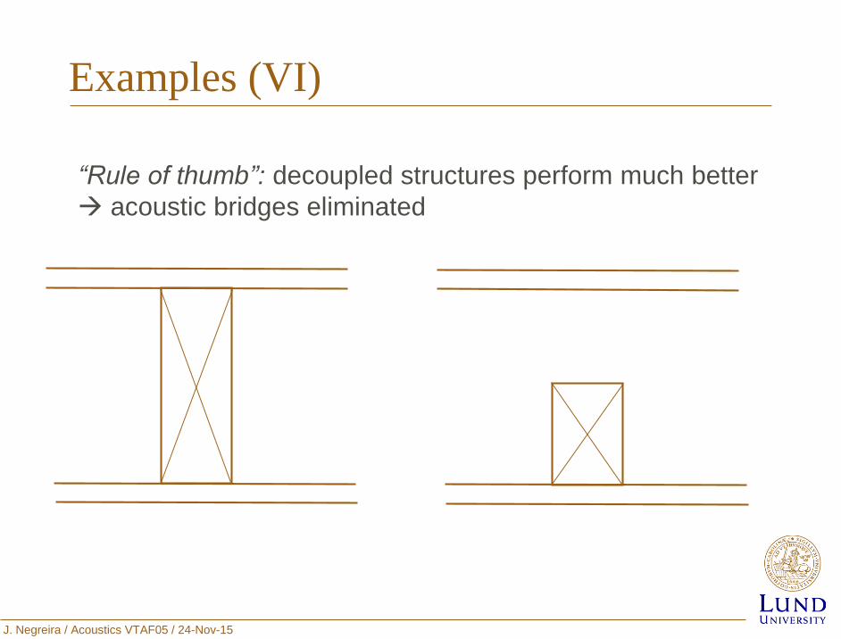
Examples (VI)
“Rule of thumb”: decoupled structures perform much better
acoustic bridges eliminated
J. Negreira / Acoustics VTAF05 / 24-Nov-15
Outline
Introduction
Airborne Sound Insulation
Impact Sound Insulation
Conclusions
Analytical models for calculation of Rw in
single and double-leaf walls
J. Negreira / Acoustics VTAF05 / 24-Nov-15
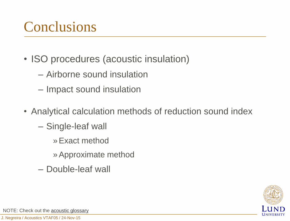
Conclusions
• ISO procedures (acoustic insulation)
– Airborne sound insulation
– Impact sound insulation
• Analytical calculation methods of reduction sound index
– Single-leaf wall
» Exact method
» Approximate method
– Double-leaf wall
NOTE: Check out the acoustic glossary
Recommended