Disclosure to Promote the Right To Information
Whereas the Parliament of India has set out to provide a practical regime of right to information for citizens to secure access to information under the control of public authorities, in order to promote transparency and accountability in the working of every public authority, and whereas the attached publication of the Bureau of Indian Standards is of particular interest to the public, particularly disadvantaged communities and those engaged in the pursuit of education and knowledge, the attached public safety standard is made available to promote the timely dissemination of this information in an accurate manner to the public.
इंटरनेट मानक
“!ान $ एक न' भारत का +नम-ण”Satyanarayan Gangaram Pitroda
“Invent a New India Using Knowledge”
“प0रा1 को छोड न' 5 तरफ”Jawaharlal Nehru
“Step Out From the Old to the New”
“जान1 का अ+धकार, जी1 का अ+धकार”Mazdoor Kisan Shakti Sangathan
“The Right to Information, The Right to Live”
“!ान एक ऐसा खजाना > जो कभी च0राया नहB जा सकता है”Bhartṛhari—Nītiśatakam
“Knowledge is such a treasure which cannot be stolen”
“Invent a New India Using Knowledge”
है”ह”ह
IS 802-2 (1978): Code of Practice for Use of StructuralSteel in Overhead Transmission Line Towers, Part 2:Fabrication, Galvanizing, Inspection and Packing [CED 7:Structural Engineering and structural sections]

IS : 802 ( Part II ) · 1978( Reaffirmed 2010 ).
Indian Standard
CODE OF PRACTICE FORUSE OF STRUCTURAL STEEL IN OVERHEAD
TRANSMISSION LINE TOWERS
PART II FABRICATION, GALVANIZING, INSPECTIONAND PACKING
( Fourth Reprint APRIL 2000 )
UDC 621.315.668.2:006.76
© Copyright 1979
BUREAU OF INDIAN STANDARDSBHAVAN, 9 BAHADUR SHAH ZAFAR MARG
NEW DELHI 110002
Gr 3 February 1979
IS I 802 ( Part 0 ) • 1171
Indian StandardCODE OF PRACTICE FOR
USE OF STRUCTURAL STEEL IN OVERHEADTRANSMISSION LINE TOWERS
PART II FABRICATION, GALVANIZING, INSPECTIONAND PACKING
Structural Engineering Sectional Committee, 5MBDC 7
Chai,mQfI
DIRECTOR STANDARDS ( CIVIL)
R.JW'Ultlin,
Ministry or Railway.
SBRI R. M. AGARWAL IDatitution ofEDgincer. ( India ), CalcuttaDR SRAlI.BER PRAKASH (AlImuJl')
Saar A. K. BAN.RIBI: Metallurgical aDd EDliDeeriDI Con.ultaDti (India )Ltd, Ranchi
SHIU S. SAlfKABAN (AllmuJ" )SKJn S. N. BA8t7 lDapection Wing, Directorate General of Supplies
and Dispoaal., New DelhiSBln D. B.JAt. (AIImt.,. )
SSRI P. C. BHASIN Ministry of Shipping and Transport ( Department orTran.port ) ( Roada Win, )
SaRI V. S. BBIDK Central Water CommiuioD, New DelhiDEPUTY Dm_CToB (GATE'
AoND DI:810M8 ) ( AI,,,,.,,,, )DR p. N. CBATTERJI:II: Government OrWell BenplDa P. DAYARATNAJI Indian rnatitute or TeclmolOlY, KanpurSHIn D. S. DUAl M. N. D.atur & Co Pvt Ltd, Calcutta
SSRI S. R. KULL\aNI ( AI,,,,,.,, )DIHBoroR ( TJtA.IKIUIOM ) Central Electricity Authority. New Delhi
DnUTY DIRECTOR ( 1'BAI'I-MISSION) ( Alt,""", )
JOINT DIs.eTOR STA.DARDe Ministry or R.ailway.( B & S)
A88IITAIIT D I • II: 0 TOR( B &t S }.SB ( Alt,NUlt, )
S••I K. K. KBA••A NatioDal BuildiDls OllaniDtioD, New DelhiS..I K. S. S&lWlYAIAX ( .AI,.,,,,d, )
(~"",,2)
C) C-t1ri"t 1979BUIlEAU OP INDIAN STANDAIlDS
Tbi. publicatioD iI protected UDder the 1__ ~,j, Ad ( XIV of 1957) ...reproduCtlOD iD whole or in part by"" meaal _cepe wiclawritteD peraailaioa 01 thepublisher thall be deemed to be aD iDfriJaplDCDt or c:oPJrilht UDder tM .icI Act.
IS I 802 ( Part II ) • 1978
( C.,.'i~tl from 'd" 1 )
Director Q.eneral, BIS{ Ex-tJfficio M,mber )
Bombay Port Trust, BombayEngineers India Ltd, New Delhi
Hindustan Steel Works Construction Ltd, CalcuttaRichardson & Cruddas Ltd, Bomba y
Mtmb,rs R,prls,nt;",SHRI P. K. MAJ.LICK: Jeuop & Co Ltd, CalcuttaSURI P. K. MUJtHnJBE Braithwaite & Co ( India) Ltd, Calcutta
SURI P. T. PATEL ( AII,mal, )5BBI S. MUJtHBRJEE Hindustan Steel Ltd, DurgapurSHIll S. K. MUXBERJEl!: Bridge & Roof Co ( India) Ltd, Howrah
SBJU B. K. CHATTERJEE ( Alurnat« )SBBI P. N. BBAIKARAN NAm Rail India Technical and Economics Services,
New DelhiSBBI A. B. RIBEIRO' Alumau )
SURI R. NARAYANAN Structural Engineering Research Centre (CSIR),Roorkee
Engineer-in-Chief'! Branch. Ministry of DefencePRO)' H. C. PARME8HWARAM
SKRI C. S. S. RAO ( Ait,rn"t, )SURI DILIP PAUL Industrial Fasteners Association of India, CalcuttaREPRESENTATIVB Burn Standard Co Ltd, Howrah
SHRI A. P. KAYAL ( All,rnat,)RXPRB:SENTATIVF.:
RURESJ£NTATIVE
SHRI p. V. NAIl( ( Alternate )SURI P, SKNOUPTA Stewarts & Lloyds of India Ltd, Calcutta
SHRI M. M. GHOSH ( A.lternat,)SHIU G. SRINIVAS.'N Bharat Heavy Electricals Ltd, Tiruchirapalli
SURI G. L. NARA8AIAIi ( Alurnau )SH'RI D. SRINIVASAN Joint Plant Committee, C.aJcutta
SHRI B. P. GHOSB ( Alt4r1lat. )Snnr M. D. THAMBEXARSURJ L. D. WADHWA
SHRI R. R. NAG ( Alternau )SlIRJ C. R. I{AMA RAO,
Director ( Struc & Met)
Sterl/tJry
Srmr S. S. SETHI
Assistant Director ( Struc & Met), HIS
Subcommittee for Code of Practice for Use of Steel in OverheadTransmission Line Towers, 5MBDC 7 : 1
C01lvnu,
SUBI V. D. ANAND Central Electricity Authority, New Delhi
M.mb,rsSHftJ H. S. SERRA ( .Alt4,,.al4 to
Shri V. D. Anand)Snnr M, ARUMUHAM
AS818TANT DIRECTOR STANDARDS
(B&5)·1DEPUTY DIRECTOR' STAND....D. (C-OHE) ( Alt,rnal, )
Tamil Nadu Electr icity Board, MadrasMinistry of Railways
( CiJtUin_d '" ~QI' 10 )
2
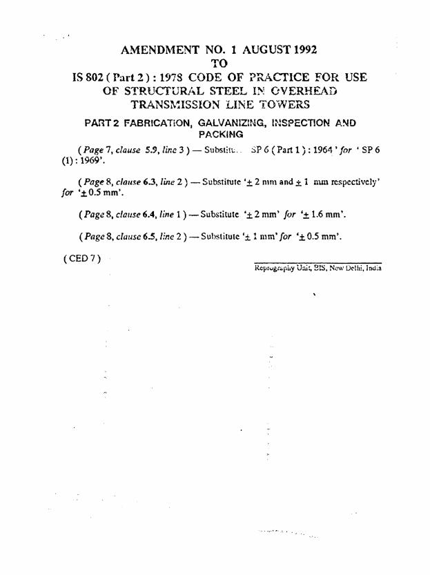
AMENDl\1ENT NO. 1 AUGUST 1992TO
IS 802 ( Part 2 ) : 1978 CODE OF PRACTICE FOfC. USEOF STRUCTURJ-'l.L STEEL I!'! OVERHEAD
TRANS~~ISSION LINE TovVVERS
PART2 FABRICATiON, GALVANIZlr~G, l~~S?ECTION A~D
PACKIf'IG
(Page 7, clause 5.9) line 3 ) - Substitu. - SP 6 (Part 1 ) : 196~ , for • SP 6(1): 1969'.
(Page 8, clause 6.3, line 2 ) - Substitute '± 2 rum and ± 1 mm respectively'for '.±O.5 mm'.
(Page 8. clause6.4, line 1 ) - Substitute '± 2 nun) for '± 1.6 mm'.
(Page 8, cliJUSC 6.5, line 2 ) - Substitute '± 1 mm' for '±0.5 mm'.
(CEO 7)ReprugtQphy U,li:, SIS. New Delhi. India
'" , .... i ,. ••~ , ..
IS :. 802 ( Part n ) · 1978
Indian StandardCODE OF PRACTICE FOR
USE OF STRUCTURAL STEEL IN OVERHEADTRANSMISSION IJINE TOWERS
PART II FABRICATION. GALVANIZING t INSPECTIONAND PACKING
o. FOR E W 0 R D
0.1 This Indian Standard ( Part II) was adopted by the Indian StandardsInstitution on 25 October 1978, after the draft finalized by the StructuralEngineering Sectional Committee had been approved by the Structuraland Metals Division Council and the Civil Engineering Division Council.
0.2 With the publication of IS : 802 ( Part I )-1977*, provisions regardingloads, material, permissible stresses and design aspect have been covered.In this part requirements regarding fabrication, galvanizing, inspectionand packing of overhead transmission line towers have been covered.
0.3 This standard keeps in view the practices being followed in thecountry in this field. Asaistance has been derived from the 'Guide fordesign of steel transmission line towers t issued by the American Societyof Civil Engineers.
0.4 For the purpose of deciding whether a particular requirement of thisstandard is complied with, the final value, observed or calculated,expressing the result of a test, shall be rounded off in accordance withIS : 2· 1960t. The number of significant places retained in the roundedoff value should be the same as that of the specified value in thisstandard.
I. SCOPE
1.1 This standard ( Part II ) covers the provisions relating to the fabrication, galvanizing, inspection and packing requirements of self-supportingIteellattice towers for overhead transmission lines.
1.1.1 Provisions regarding loads, permissible stresses and designconsiderations have been covered in Part I of this standard.
• Code of practice for use of structural steel in overhead transmission line towers:P.rt I Loada and permiuible allellCl ( Slt(111tJ "pasion ).
tRules for rounding oft" numerical values ( r,,,iSld ).
3
II•• (PartD) ·1978
1.1.2 Pr()visiofts regarding testing of tower. have be~n covered inPart III of this standard.
1.1.3 For provisions regardiDI erection of towers, reference shall bemade to IS: 5613 ( Part II/Sec 2 )-1976*.1.2 This code does not cover guyed towers and special towers for river'croning or other long spans. These wil] be covered by separate codes.
2. PLAN AND DRAWING
2.1 Plan. and drawings shall be prepared according to IS: 696-1972tand IS: 962-1961~.
2.2 Strllctaral A••embly Drawl_••2.2.1 The drawings shall show the complete design dimensions, member
length, slope (acton or triangles, section sizes, bend lines, gauge lines,diameter, length and number of bolts, spacers, washers, sizes of gussetplates, position of holes, etc, and relative location of various members.
2.2.1.1 Sufficient number of elevation, crOIS section and plan views.hall be presented to clearly indicate the details ofjoints and arrangementof member•.
2.2.2 All members shall be clearly shown and the respective identification mark allotted to each member.
2.2.3 The drawings shall be drawn to a scale large enough to conveythe information adequately.
2.2.4 All connections shall be detailed to minimize eccentricity of theconnection.
NOTII- Due consid....tion shan be riven to the additional stresses introduced inthe member. on account oreccentricity of the connection.
2.3 5laop DrawiDI- Shop drawings, containing complete informationnecessary for fabrication of the component part. of the structures shall beprepared. These drawings shall clearly show the member sizes, lengthand marks, hole positionl, gauge lines, bend Jines, edge distances, amountof clipping, notching, etc.
2.'.1 In the case of members to be bent, the shop drawings shallindicate provision for the variation in length to be made.
2.4 Bill of Materi.l- Bill of material for each type of tower shall beprepared separately. This shall indicate grade of steel, mark numbers,
*Code or practice for design, jllltallation and m:\intnance of overb..ad power Iines ;Part II Lines above 11 kV up to and includio. 220 kV. Section 2 Installation andmaintenance.
fCode of practice for general cn.incerin, drawiDls ( "e."tI ,61J;,iD,. ).*Code of p,",ctice for architectural and buildinl drawin. <first ,ms;'" ).
4
18 I 802 ( Part U ) • 1978
section sizes, member lengths, their calculated weights, number of bolts,nuts and washers and their sizes, total quantities required and structuraldrawing numbers.
2.4.1 No reduction in weight due to drilling, punching of bolt holes,screw cuts, clipping, notching, chamfering, etc, shall be made whilecomputing the calculated weight of the members.
3. FABRICATION3.1 GeDeral- The fabrication of transmission line towers shall be donein accordance with this code A reference may, however, be made toIS : 800-1962· in case of non-stipulation of some particular provision inthis standard.
3.2 Material Quality COlltrol- In cases where more than one gradeof steel is used in the structural members, proper identification marks ofthe various grades ofsteel being used shall be made on the material toensure their ultimate use in the proper location in the towers before takingup the fabrication.
4. OPERATIONS IN FABRICATION4.1 StraightemD, - All material shall be reasonably straight and, ifnecessary, before being worked shall be straightened and/or flattened bypressure, unless required to be of curvilinear form and shall be free fromtwists. Straightening shall not damage the material. The adjacentsurfaces of the parts when assembled, shall be in close contact throughout keeping in view the tolerances specified. Hammering shall not bepermitted for straightening and/or flattening of members. Sharp bendsshall be cause for rejection.
4.2 Cuttiag - Cutting may be effected by shearing, cropping, flamecutting or sawing. The surfaces so cut shall be clean, smooth, reasonably square and free from any distortion.
4.3 BeDdiDIf.3.1 Mild steel angle sections up to 75 X 75 mm ( up to 6 mm thick)
shall be bent cold up to and including bend angle of 10°; angles above75 X 75 mm (thicknesl up to 6 mm) and up to and including100 X 100 mm (thickness up to 8 mm ) may also be bent cold up to "thebend angle of 5°. All other angle sections and bend angles not coveredabove shall be bent hot.
4.3.2 All plates up to 12 mm thickness shall be bent cold up to amaximum bend angle of 15°. Greater bends and other thicknesses shallbe bent hot.
4.3.3 Bends on all high tensile steel sections shall be done hot.
·Code or practice for usc of structural steel in general building conltruction ("lIis,~ ).
5
11._ ( hre D ). 11'71
Ut All hot beDt material 'hall be air cooled.
4.S.5 The bends lhall be of even profile and Cree from any surfaceclamaB-·~t BeHq
4.4.1 Holes in the memben Ihall either be drilled or punched to jigand shall Dot be formed by flame cutting process. All burn left bypunching or drilling ahall be completely removed•
...4.2 Punching may be .d~pted Cor sectionI up to 12 mm thick. Forthicker lecnon., drilling shall be done.
4.4.3 The boles near the bend line of. bent member, on both sides ofbend line, shall be pUDched/drilled after bending and relative poaition ofth_ boles .ball be maintained with the Ule or proper template/jiga andhtura.
5. P.IUNDS AND JOINTS
5.1 0.••""- It Iball be .IUred that the futenen provisle politiveattachment at .11 times and under the conditioDi when the toweratructur.. are lubjected to vibratory load ••
U .1&. - Boltl used for erection of transmiaion line tower shallpreferably be oC 12, 16 and 20 mm diam.er and in no cue bolt diameter.hall be leu than 12 mm.
5.2.1 Only ODe diameter of bolts sball preferably be wed in one towertype.
5.2.2 The leDlth of the bolt .ball be luch that the threaded portiondoes not lie in the plaae of contact of membe...
5.2.3 It thall alia be ensured that the threaded portion of the boltprotrudu Dot len than 3 mID and not more than 8 mm over the nut afterIt i. fully dahtened.
U Hoi. ",... Boltial - Holes Ihall be cylindrical. Oval or lobed(orml or hola Ihall Dot be permitted. The diameter or the hole aball beequal to the diameter of the bolt plua 1-5 mm.
5.3.1 Hoi. Ihall be perpendicular to the platel or augles.
5.S.2 The accuracy or the location of hoI...hall be sueh that for anygroup of memben when ...embled the holes .haJl admit tbe bolt at rightangle to the plane or connection.
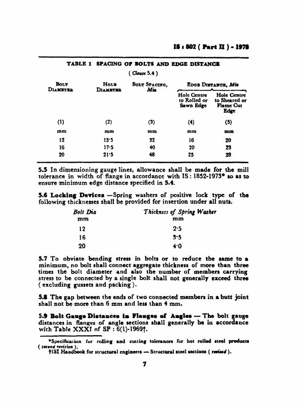
5.4 Spa'" of .It...cI".e OI.t... - The minimum Ipacinlofbolta aad eel,. diltaaC8 mall be u liYeD in Table I.
e
.1 • 802 ( Part D ) • 1171
TABLE 1 SPACING OF BOLTS AND EDGE DUTANCB
(Cl4u, 5.4)
BoLT HOL. BoLT SPAOIHO, EDOB DtftAB'oz. MittDUJOTBB DLUlftD Mia , A ...
Hole Centre Hole Centreto Rolled or to Sheared orSawn Edge Flame Cut
Edae
(1) (2) (3) (4) (5)
mm mm mm mm mID
12 13·5 !2 16 2016 17·5 40 20 2320 21-5 48 25 28
5.5 In dimensioning gauge lines, allowance shall be made (or the milltolerance in width of flange in accordance with IS: 1852-1973- 10 as toensure minimum edge distance specified in 5.4.
5.6 LocldDI DeYlce. -Spring washers of positive lock type of thefollowing thicknesses shall be provided for insertion under all nuts.
Bou Di« Thickness of Sprin, Wah"mm mm
1216
20
5.7 To obviate bending stress in bolts or to reduce the same to •minimum, no bolt ,h.ll connect aggregate thickness of more than threetimes the bolt diameter and also the Dumber or memben carryingstress to be connected by a single bolt shall not generally exceed three(excluding gussets and packing ).
5.1 The gap between the ends of two connected member. in a butt jointshall not be more than 6 mm and lesl than 4 mm,
5.t Bolt G•••_ Dl.taDc•• I. 'I••••• • 1 A_.I.. - The bolt gaupdistances in ftan~es of angle sections .hall generaJly be in accordancewith Table XXXI of SP : 6(1)-1969t.
·Specification fur roUins aDd cuuins tolaancn for hot rolled ateel product.( I.,nd r,rtili,,. )_
tlSI HaDdbook for structural en,iDeera - Structural Itcel acctiODI ("..~).
7
II I 802 (PArt II ) • 197'
6. TOLERANCES1.1 Fabrication tolerances shall conform to those specified in 6.2 to 6.5.Tolerances not specified in this code shall in general conform toIS : 7215e1974*.6.2 The maximum allowable difference in diameter of the holes on thetwo sides of. plate or angle shall be 0-8 mm, that is, the allowable taperin a punched hole shall not exceed 0·8 mm on diameter.6.3 Tolerance cumulative and between consecutive holes shall bewithin ::I: 0-5 mm,6.4 Tolerance on the overall length of a member shall be within ± 1·6 mm.6.5 Tolerance on gauge distance shall be within :I: 0·5 mm.
7. MARKING1.1 The identification mark allotted to each member shall be distinctlystamped before galvanizing with marking dies of 16 mm size.
L SHOP BRECTION1.1 The steel work sball be temporarily shop erected complete inhorizontal or vertical position ( one tower of each type including everycombination of leg extensions) so that accuracy of the memben maybe checked before commencing mas. fabrication.
I. PAINTING AND GALVANIZING9.1 PalaU. - Preparation of surface for painting ( pretreatment) andapplication of primer and finilhing coats shall be done in accordancewith the relevant clauses of IS : 1477 (Part I )-1971t and IS : 1477( Part II )-1971: respectively.
9.1.1 The pretreatment to the members and application of primer coat.hall be done immediately after fabrication. Another primer coatfollowed by two coati of finishing paint sball be given at site after thefabricated -Iteel work iJ erected. In cue the primer coat Ii scrapedduring transportatioD, the member .urface Iball be cleaned before applying the primer coat in the field .• .2 Gal....... - Boltl and other rastenerl .hall be ,.Ivaniaed inaccordance with IS : 5358-19691 galvanizin. of melDben of the tower.h.11 conform to IS : 4759-196811 and .prill. wasbers .hall be 1.lvanizedin accordance with IS : 1573-1970,.
*ToI..aCel for '.bricadoD or Iteel ItruetUreI.tOode ofpractice r. paiDtiD, 01 la-roUi mctaJa ia buiJcIiDp: Part I PretnatmeaI
(Jr'I, ..... ). .~Code 01pracdce '01' palDdDa or rerroUi met" iD buUd1Dp: Part n Paiatial·
(,II.,,.....).I8Peci&catioD lor 1Iot-dlp plYaDbcd coatiDp _ ruteaen.lSiMd..... lor Iao&-clip aiDecoatill. OD I&iuct1IraI .... ucI.&II. alii_ ........'8,-",.electroplated coatiap far .bae _ ina aD" ....
•
IS t 802 ( Part II ) • 1978
10. INSPECTION
10.1 The inspector shall have free access at all reasonable times to thoseparts of the manufacturer's works which are concerned with thefabrication of the steel work and shall be afforded all reasonable facilitiesfor satisfying himself that the fabrication is being done in accordancewith the provisions of this standard.
10.2 Unless specified otherwise, inspection shall be made at the placeof manufacture prior to despatch and shall be conducted so as not tointerfere unnecessarily with the operation of the work.
10.3 The manufacturer shall guarantee compliance with the provisionsof this standard, if required to do so by the purchaser.
10.4 Should any member of the structure be found not to comply withany of the provisions of this standard, it shall be liable to rejection. Nomember once rejected shall be resubmi tted for inspection, except in caseswhere the purchaser or his authorized representative considers the defectas rectifiable.
10.5 Defects which may appear during fabrication shall be made goodwith the consent of and according to the procedure laid down by theinspector.
10.6 All gauges and templates necessary to satisfy the inspector shall besupplied by the manufacturer.
10.7 The correct grade and quality of steel shall be used by the manufacturer. To ascertain the quality of steel used, the inspector at hisdiscretion may get the material tested at a suitable or approvedlaboratory.
11. PACKING
11.1 Angle sections shall be wire bundled or despatched loose as may bemutually agreed upon.
11.2 Cleat angles, gusset plates, brackets, fillet plate, hanger and similarloose pieces shall be nested and bolted together in rnutiples or securelywire-d together through holes.
11.3 Bolts, nuts, washers and other attachments shall be packed indouble gunny bags accurately tagged in accordance with the contents.
11.4 The packings shall avoid losses/damages during transit. Eachbundle or package shall be appropriately marked.
9
IS I 802 ( Part II ) • 1.78
Kamataka State Electricity Board, BanploreStructural EDliDeeriDg Rnearch CeDtre (CSIR.),
RoorkeeSIUU R. NUAYAlfAB ( Al'ma.")
S"J T. K. RAIIA"ATIUX TriVeDi Struccurall Ltd, NalDi, Allahabad8 1 K. V. S. MUaTHY ( ( AllmtiIll)
R. mr.rATn'JD Bhakra MaDasemeat Board. ChudiluhSBBI Nm.I.DD Suro. ( AI"".." )
SBBI A. P. SR.... Madhya Pradesh Electricity Board. JabalpurS.BI N. St.n Bihar State Electricity Board, PatD.S"I S. N. Vo... IDapection "'in., Directorate General or Supplia
and Di.poulJ, New Delhi
( C.,,'inutd /,.", /HII' 2 )
M,,,.w, R,/,t",IIIi_,SOl S. K. BBATTAOBABJ.. SAE ( India) Ltd. Calcutta
SaRI V. NABAYANAlf ( ~ll,,,,.,, )CRIE.. ENGman Andhra Pradesh Electricity Board, Hyderabad
SVPDJ:NTENDt1fO ENolnEB ( All"".,.)SRI K. R. Do Damodar Valley Corporation, Calcutta
SRBI SWABA" GUPTA (Altnll.")SRJlI J. C. GUPl'. Be.. ConltructiOD Board. ChandiprbSRILI J. C. GUtTA U. P. State Electricity Board, Lucbow
SHRI V. B. SmOB ( AlIImat, )SHRI O. KHOSLA EMC Steeb) Ltd, Calcutta
Ssal S. N. SINOH ( Allmltlll )SBRI S. N. MISRA Mabarashtra State Electricity Board, Bomba,
SlIal S. R. JoeBI ( AII".,.«', )S8•• NI••AlB SINOH Punjab State Electricity Board. ChandiprhSuaJ N. D. PAalKR Kamani EnlineeriDI Corporation Ltd, Bombay
501 S. D. DdD ( AI,,,,..,, )Smu R. N. Pmrl>8. Tata Hydro Electric Power Supply Co Ltd, Bombay
DRR.. Roll" AX ( All'''''''' )SOl P. V. RAMAIA.SBIU N. V. RAMAl(
10
BUREAU OF INDIAN STANDARDS
H••dqu.rter~Manak Bhavan, 9 Bahadur Shah Zafar Marg, NEW DELHI 110002Telephones: 323 0131, 323 3375, 3239402 Fax:+ 91 011 3234062,3239399, 3239382E • m.1I : [email protected]. Internet: http://wwwdel.vsnl.net.inlbis.org
Centr.1 L.boratory :
Plot No. 20/9, Site IV, Sahibabad Industrial Area, Sah ibabad 201010
Region.' Offlc..:
Central: Manak Bhavan, 9 Bahadur Shah Zafar Marg, NEW DELHI 110002
-Eastem: 1/14 CIT Scheme VII, V.i.P. Road, Kankurgachi, CALCUTTA 700054
Northern: SCC 335·336, Sector 34-A, CHANOIGARH 160022
Southern: CJ.T. Campus, IV Cross Road, CHENNAI600113
fWestem : Manakalaya, E9, MIOC, Behind Maral Telephone Exchange,Andheri (East), MUMBAI 400093
S,.nch Offlc..:
'Pushpak" Nurmohamed Shaikh Marg, Khanpur. AHMEDABAD 380001
*Peenya Industrial Area, 1at Stage, Bangalore-Tumkur Road,BANGALORE 560058
Telephone
770032
323 76 17
3378662
603843
235 2~ 15
832 9295
550 1348
8394955
7234 52
5251 71
262808
323635
368586
3221 04
403627
21 01 41
288801
71 19 98
5411 37
320 1084
373879
21 6876
Road, 21 8923
Commercial-cum-Offioe Complex, Opp. Dushera Maidan, E-5 Arera Colony,Bittan ~"ket. BHOPAL 462016
62/63, Ganga Nagar, Unit VI, BHUBANESWAR 751001
Kalal Kathlr Building, 670 Avinashi Road, COIMBATORE 641018
Plot No. 43, Sector 16 A, Mathura Road, FARIDABAD 121001
Savitrl Complex, 116 G.T. Road, GHAZIABAD 201001
53/5 Ward No.29, R.G. Barua Road, 5th By-lane, GUWAHATI781003
5-8-56C, L.N. Gupta Marg, Nampally Station Road, HYDERABAD 500001
E·52, Chltr."j." Marg, c- Scheme, JAIPUR 302001
117/418 B, Sarvoday. Nagar, KANPUR 208005
Seth Shawsn, 2nd Floor, Behind Leel. Cinema, Naval KishoreLUCKNOW 226001
NIT Building, Second Fleer, Gokulpat Market, NAGPUR 440010
Patliputralndus1rial Estate. PATNA 800013
Institution of Engineers (India) Building, 1332 Shiv';; Nagar, PUNE 411005
~ Houle' 3RtFloor, Bhak1inagar Circle, 80 Feet Road,RAJKOT 360002
T.C. No.1411~1.lkiYersIty P. O. PMlvwn, 11-tIRLNANANTHAPURAM 695034
-Sales Office is at 5 Chowringh•• Approach, P.O. Princep Street, .CALCUTTA 700072
tSIII.. Office ;. at Novelty Chambers, Grant Road, MUMBAI 400007
*S.... Office I. at 1=' Block. Unity Building, Naraahimaraja Square,BANGALORE e8OOO2
271085
309 65 28
2223971
Reprography Unit, BIS, New Delhi, India
Recommended