��������������� �����������������
��������
���
������������� ��������������� ��������������
������������
��������������� ���������������������
�� ����� ������������������������ ���

2
WARNING
WARNING
WARNINGDO NOT OPERATE THIS EQUIPMENT WITHOUT FIRST READINGAND UNDERSTANDING THIS MANUAL. IF YOU ARE UNABLE TO
UNDERSTAND THE WARNINGS, CAUTIONS, AND INSTRUCTIONS,CONTACT A HEALTHCARE PROFESSIONAL, DEALER OR TECHNI-
CAL PERSONNEL IF APPLICABLE BEFORE ATTEMPTING TO USE THISEQUIPMENT - OTHERWISE INJURY OR DAMAGE MAY RESULT.
THE INITIAL SET UP OF THIS WHEELCHAIR MUST BE PERFORMEDBY A QUALIFIED TECHNICIAN.
PROCEDURES OTHER THAN THOSE DESCRIBED IN THISMANUAL MUST BE PERFORMED BY A QUALIFIED TECHNICIAN.
SPECIAL NOTESWARNING/CAUTION notices as used in this manual apply to hazards or unsafe practiceswhich could result in personal injury or property damage.
NOTICE
INFORMATION CONTAINED IN THIS DOCUMENT IS SUBJECT TO CHANGE WITHOUT NOTICE.
WHEELCHAIR USER
As a manufacturer of wheelchairs, Invacare endeavors to supply a wide variety of wheel-chairs to meet many needs of the user. However, final selection of the type of wheelchairto be used by an individual rests solely with the user and his/her healthcare professionalcapable of making such a selection.
WHEELCHAIR TIE-DOWN RESTRAINTS AND SEAT POSITIONING STRAPS
Invacare recommends that wheelchair users NOT be transported in vehicles of any kindwhile in wheelchairs. As of this date, the Department of Transportation has not approvedany tie-down systems for transportation of a user while in a wheelchair, in a moving vehicleof any type.
It is Invacare’s position that users of wheelchairs should be transferred into appropriateseating in vehicles for transportation and use be made of the restraints made available bythe auto industry. Invacare cannot and does not recommend any wheelchair transporta-tion systems.
AS REGARDS RESTRAINTS - SEAT POSITIONING STRAPS - IT IS THE OBLIGATION OF THE DMEDEALER, THERAPISTS AND OTHER HEALTHCARE PROFESSIONALS TO DETERMINE IF A SEAT PO-SITIONING STRAP IS REQUIRED TO ENSURE THE SAFE OPERATION OF THIS EQUIPMENT BY THEUSER. SERIOUS INJURY CAN OCCUR IN THE EVENT OF A FALL FROM A WHEELCHAIR.
SAVE THESE INSTRUCTIONS

3
TABLE OF CONTENTS
TABLE
OF
CONTENTS
TABLE OF CONTENTSSPECIAL NOTES ..................................... 2
SPECIFICATIONS ..................................... 4
PROCEDURE 1 - GENERAL GUIDELINES .. 5CONTROLLER SETTINGS.......................... 5REPAIR OR SERVICE INFORMATION......... 5OPERATING INFORMATION ....................... 5SAFETY/HANDLING OF WHEELCHAIRS.... 8WARNING/CAUTION LABEL LOCATION .... 11
PROCEDURE 2 - SAFETY INSPECTIONCHECKLIST/TROUBLESHOOTING ........ 12
SAFETY INSPECTION CHECKLIST ........... 12TROUBLESHOOTING GUIDE ..................... 13
PROCEDURE 3 - WHEELCHAIROPERATION........................................... 14
WHEELCHAIR OPERATION ...................... 14
PROCEDURE 4 - ARMS .......................... 16ARMREST ANGLE ADJUSTMENT ............. 16ARMREST WIDTH ADJUSTMENT ............. 16ARMREST DEPTH ADJUSTMENT ............. 17ARMREST HEIGHT ADJUSTMENT ............17
PROCEDURE 5 - SEAT ........................... 18REMOVING/INSTALLING SEAT SUPPORT
COLLARS ............................................... 18REMOVING/INSTALLING THE SEAT
ASSEMBLY ............................................. 19ADJUSTING THE SEAT HEIGHT ................ 21ADJUSTING THE SEAT SUPPORT
POSTS.................................................... 23ADJUSTING THE SEAT DEPTH ................. 24REPLACING THE SEAT POSITIONING
STRAP .................................................... 25
PROCEDURE 6 - BACK .......................... 26FOLDING/UNFOLDING THE BACK .......... 26ADJUSTING THE BACK ANGLE ................ 26ADJUSTING THE HEADREST .................... 26
PROCEDURE 7 - FOOTBOARDASSEMBLY....................................... 27
REMOVING/INSTALLING/ADJUSTING THEFOOTBOARD ASSEMBLY....................... 27
ADJUSTING THE FOOTBOARDASSEMBLY ANGLE................................. 28
PROCEDURE 8 - SHROUD/WHEELS...... 29REPLACING THE FOAM FILLED TIRES
ONTO THE WHEEL RIM......................... 29REMOVING/INSTALLING THE SHROUD .... 29ENGAGING/DISENGAGING MOTOR
LOCKS................................................... 29REMOVING/INSTALLING THE AXLE
SHROUD COVERS ................................ 31REPLACING THE FRONT/REAR
CASTER ASSEMBLIES .......................... 31
PROCEDURE 9 - BATTERIES ................. 32REMOVING/INSTALLING BATTERIES
WITHOUT REMOVING CABLES.............. 32CONNECTING/DISCONNECTING
BATTERY CABLES.................................. 33CONNECTING/DISCONNECTING
CIRCUIT BREAKER CABLES .................. 34REPLACING BATTERIES........................... 35WHEN TO CHARGE BATTERIES............... 36CHARGING BATTERIES ............................ 36BATTERY CHARGER OPERATION ............ 38
PROCEDURE 10 - ELECTRONICS .......... 40RETRACTING THE MKIV JOYSTICK ......... 40REPOSITIONING THE MKIV JOYSTICK .... 41DISCONNECTING/CONNECTING THE
MKIV JOYSTICK ..................................... 41
PROCEDURE 11 - TRANSPORT ............. 42TRANSPORTING THE WHEELCHAIR ....... 42
PROCEDURE 12 - OPTIONS .................. 44REMOVING/INSTALLING THE CRUTCH
CANE HOLDER....................................... 44REMOVING/INSTALLING THE SAFETY
FLAG ...................................................... 44
NOTES .................................................. 45
WARRANTY ........................................... 47

4
SPECIFICATIONSPRONTO™ M6
Seat Width Range: 17 - inches
Seat Depth: 17 1/2 - inches-with headrest
Back Height Range: 21 - inches to 27 - inches - In 1 - inch increments
Back Angle Range: 80o to 115o
Seat-to-Floor: 19 1/4 to 20 3/4 - inches
Overall Width(No joystick): 23 - inches
Overall Height: 39 3/4 to 47 1/4 - inches
Overall Length 31 1/2 to 33 1/2 - inches (With Footboard Folded)42 to 44 - inches (With Footboard Down)
Drive Wheels/Tires 10 x 3 1/2 - inch (Flat Free-Standard)
Caster w/PrecisionSealed Bearings: 6.0 x 1.3 - inch Front
5.0 x 1.2 - inch Rear
Footrests/Legrests: Flip Up, Depth Adjustable
Weight1
W/O Batteries: 153 lbs.W/Batteries (Gel Cell): 205 lbs.
Shipping: 253 lbs.
Armrests: Adjustable Width, Angle, Height and Depth
Upholstery: Gray Cloth
Batteries: U1 Gel Cell - Quantity 2
PERFORMANCE
Speed (M.P.H.): 0 to 4 1/2Turning Radius: 24-inchesRange (variable)2: 14 miles� Weight Limitation: 250 lbs.
� NOTE: Refer to PERCENTAGE OF WEIGHT DISTRIBUTION in PROCEDURE 1 of this manual.
Footnotes:1. Includes seating systems and accessories.2. Range will vary with battery conditions, surface, terrain and operators weight.
SPECIFICATIONS
SPECIFICATIONS
5
This Procedure Includes the Following:
Controller Settings
Repair or Service Information
Operating Information
Safety/Handling of Wheelchairs
Warning/Caution Label Location
WARNINGREPAIR OR SERVICE/CONTROLLER SETTINGSSet-up of the Electronic Control Unit is to be performed ONLY by a qualified technician. The finaltuning adjustments of the controller may affect other activities of the wheelchair. Reprogram-ming the controller reduces the stability/controllability of the wheelchair. Other program set-tings could cause the wheelchair to tip over resulting in serious injury to the user and/or dam-age to the surrounding property. If any individual other than a qualified technician performsany work on these units, the warranty is void.
OPERATING INFORMATION
GENERAL WARNINGSPerformance adjustments should only be made by professionals of the healthcare field orpersons fully conversant with this process and the driver's capabilities. Incorrect settings couldcause injury to the driver, bystanders, damage to the chair and to surrounding property.After the wheelchair has been set-up, check to make sure that the wheelchair performs to thespecifications entered during the set-up procedure. If the wheelchair does NOT perform tospecifications, turn the wheelchair OFF immediately and reenter set-up specifications. Repeatthis procedure until the wheelchair performs to specifications.ALWAYS shift your weight in the direction you are turning. DO NOT shift your weight in the oppo-site direction of the turn. Shifting your weight in the opposite direction of the turn may cause theinside drive wheel to lose traction and the wheelchair to tip over.DO NOT shift your weight or sitting position toward the direction you are reaching as the wheel-chair may tip over.DO NOT engage or disengage the motor locks until the power is in the OFF position.DO NOT operate on roads, streets or highways.DO NOT climb, go up or down ramps or traverse slopes greater than 9o.DO NOT attempt to move up or down an incline with a water, ice or oil film.DO NOT attempt to drive over curbs or obstacles. Doing so may cause your wheelchair to turnover and cause bodily harm or damage to the chair.DO NOT use parts, accessories, or adapters other than those authorized by Invacare.DO NOT leave the power button ON when entering or exiting your wheelchair.DO NOT stand on the frame of the wheelchair.DO NOT stand on the flip-up footboard. When getting in or out of the wheelchair, make surethat the flip-up footboard is in the upward position .ALWAYS wear your seat positioning strap.
GENERAL
GUIDELINES
GENERAL GUIDELINES PROCEDURE 1

6
GENERAL GUIDELINESPROCEDURE 1
GENERAL WARNINGS (CONTINUED)ACCESSORIESEXTREME care should be exercised when using oxygen in close proximity to electric circuits.Contact your oxygen supplier for instruction in the use of oxygen.
BATTERIESThe warranty and performance specifications contained in this manual are based on the useof deep cycle gel cell or sealed lead acid batteries. Invacare strongly recommends their useas the power source for this unit.Carefully read battery/battery charger information prior to installing, servicing or operating yourwheelchair.
CHARGING BATTERIESCarefully read all warnings, cautions and any other information printed on the battery chargerprior to recharging the batteries.
NEVER attempt to recharge the batteries by attaching cables directly to the battery terminals.
DO NOT attempt to recharge the batteries and operate the wheelchair at the same time.
DO NOT attempt to recharge the batteries when the wheelchair has been exposed toANY type of moisture.
DO NOT attempt to recharge the batteries when the wheelchair is outside.
DO NOT sit in the wheelchair while recharging the batteries.
DO NOT attempt to recharge the batteries using BOTH the on-board battery charger AND anindependent battery charger (plugged into the joystick charger port) at the SAME time. Doingso will reduce the life of the batteries.
GROUNDING INSTRUCTIONS:DO NOT, under any circumstances, cut or remove the round grounding prong from any plugused with or for Invacare products. Some devices are equipped with three-prong (grounding)plugs for protection against possible shock hazards and fire. Where a two-prong wall recep-tacle is encountered, it is the personal responsibility and obligation of the customer to contacta qualified electrician and have the two-prong receptacle replaced with a properly groundedthree-prong wall receptacle in accordance with the National Electrical Code. If you must usean extension cord, use ONLY a three-wire extension cord having the same or higher electricalrating as the device being connected. In addition, Invacare has placed RED/ORANGE WARN-ING TAGS on some equipment. DO NOT remove these tags.
RAIN TESTINVACARE has tested it’s power wheelchairs in accordance with ISO 7176 Part 9 “Rain Test”. Thisprovides the end user or his/her assistant sufficient time to remove his/her power wheelchair froma rain storm and retain wheelchair operation.DO NOT leave power wheelchair in a rain storm of any kind.DO NOT use power wheelchair in a shower or leave it in a damp bathroom while taking a shower.DO NOT leave power wheelchair in a damp area for any length of time.Direct exposure to rain or dampness will cause the chair to malfunction electrically and me-chanically; may cause the chair to prematurely rust or may damage the upholstery.Check to ensure that the red and black battery terminal caps are secured in place, joystick boot isNOT torn or cracked where water can enter and that all electrical connections are secure at all times.DO NOT use the joystick if the boot is torn or cracked. If the joystick boot becomes torn orcracked, replace IMMEDIATELY.
GENERAL
GUIDELINES

7
GENERAL
GUIDELINES
GENERAL GUIDELINES PROCEDURE 1
GENERAL WARNINGS (CONTINUED)WEIGHT TRAININGInvacare DOES NOT recommend the use of its wheelchairs as a weight training apparatus. Invac-are wheelchairs have NOT been designed or tested as a seat for any kind of weight training. Ifoccupant uses said wheelchair as a weight training apparatus, INVACARE SHALL NOT BE LIABLEFOR BODILY INJURY AND THE WARRANTY IS VOID.
WEIGHT LIMITATIONThe Pronto™ M6 model has a weight limitation of 250 lbs.
WARNINGCAUTION: IT IS VERY IMPORTANT THAT YOU READ THIS INFORMATION REGARDING THE POS-SIBLE EFFECTS OF ELECTROMAGNETIC INTERFERENCE ON YOUR POWERED WHEELCHAIR.
ELECTROMAGNETIC INTERFERENCE (EMI) FROM RADIO WAVE SOURCES
Powered wheelchairs and motorized scooters (in this text, both will be referred to as pow-ered wheelchairs) may be susceptible to electromagnetic interference (EMI), which isinterfering electromagnetic energy (EM) emitted from sources such as radio stations, TVstations, amateur radio (HAM) transmitters, two way radios, and cellular phones. The inter-ference (from radio wave sources) can cause the powered wheelchair to release its brakes,move by itself, or move in unintended directions. It can also permanently damage thepowered wheelchair's control system. The intensity of the interfering EM energy can bemeasured in volts per meter (V/m). Each powered wheelchair can resist EMI up to acertain intensity. This is called its "immunity level." The higher the immunity level, the greaterthe protection. At this time, current technology is capable of achieving at least a 20 V/mimmunity level, which would provide useful protection from the more common sources ofradiated EMI. This powered wheelchair model as shipped, with the INT/DL40i Non-Pro-grammable (NP) electronics, has an immunity level of unknown.
There are a number of sources of relatively intense electromagnetic fields in the everydayenvironment. Some of these sources are obvious and easy to avoid. Others are not appar-ent and exposure is unavoidable. However, we believe that by following the warningslisted, your risk to EMI will be minimized.
The sources of radiated EMI can be broadly classified into three types:
1) Hand-held Portable transceivers (transmitters-receivers with the antenna mounteddirectly on the transmitting unit. Examples include: citizens band (CB) radios, "walkietalkie," security, fire, And police transceivers, cellular telephones, and other personalcommunication devices. **NOTE: Some cellular telephones and similar devices trans-mit signals while they are ON, even when not being used;
2) Medium-range mobile transceivers, such as those used in police cars, fire trucks, am-bulances, and taxis. These usually have the antenna mounted on the outside of thevehicle; and
3) Long-range transmitters and transceivers, such as commercial broadcast transmit-ters (radio and TV broadcast antenna towers) and amateur (HAM) radios.
NOTE: Other types of hand-held devices, such as cordless phones, laptop computers,AM/FM radios, TV sets, CD players, cassette players, and small appliances, such as electricshavers and hair dryers, so far as we know, are not likely to cause EMI problems to yourpowered wheelchair.

8
GENERAL GUIDELINESPROCEDURE 1
GENERAL
GUIDELINES
SAFETY/HANDLING OFWHEELCHAIRS“Safety and Handling” of the wheelchair requires theclose attention of the wheelchair user as well as theassistant. This manual points out the most commonprocedures and techniques involved in the safe op-eration and maintenance of the wheelchair. It is im-portant to practice and master these safe techniquesuntil you are comfortable in maneuvering around thefrequently encountered architectural barriers.
Use this information only as a “basic” guide. The tech-niques that are discussed on the following pages havebeen used successfully by many.
Individual wheelchair users often develop skills todeal with daily living activities that may differ fromthose described in this manual. Invacare recognizesand encourages each individual to try what worksbest for him/her in overcoming architectural obstacles
WARNINGSPOWERED WHEELCHAIR ELECTROMAGNETIC INTERFERENCE (EMI)
Because EM energy rapidly becomes more intense as one moves closer to the transmittingantenna (source), the EM fields from hand-held radio wave sources (transceivers) are of spe-cial concern. It is possible to unintentionally bring high levels of EM energy very close to thepowered wheelchair's control system while using these devices. This can affect powered wheel-chair movement and braking. Therefore, the warnings listed are recommended to preventpossible interference with the control system of the powered wheelchair.
Electromagnetic interference (EMI) from sources such as radio and TV stations, amateurradio (HAM) transmitters, two-way radios, and cellular phones can affect powered wheel-chairs and motorized scooters. Following the warnings listed below should reduce thechance of unintended brake release or powered wheelchair movement which couldresult in serious injury.
1) Do not operate hand-held transceivers (transmitters receivers), such as citizens band(CB) radios, or turn ON personal communication devices, such as cellular phones,while the powered wheelchair is turned ON;
2) Be aware of nearby transmitters, such as radio or TV stations, and try to avoid comingclose to them;
3) If unintended movement or brake release occurs, turn the powered wheelchair OFFas soon as it is safe;
4) Be aware that adding accessories or components, or modifying the powered wheel-chair, may make it more susceptible to EMI (Note: There is no easy way to evaluatetheir effect on the overall immunity of the powered wheelchair); and
5) Report all incidents of unintended movement or brake release to the powered wheel-chair manufacturer, and note whether there is a source of EMI nearby.
IMPORTANT INFORMATION
1) 20 volts per meter (V/m) is a generally achievable and useful immunity level againstEMI (as of May 1994) (the higher the level, the greater the protection);
2) The immunity level of this product is unknown.
that they may encounter, however, ALL WARNINGSand CAUTIONS given in this manual MUST be fol-lowed. Techniques in this manual are a starting pointfor the new wheelchair user and assistant with “safety”as the most important consideration for all.
Stability and Balance
WARNINGALWAYS wear your seat positioning strap.
To assure stability and proper operation of your wheel-chair, you must at all times maintain proper balance.Your wheelchair has been designed to remain up-right and stable during normal daily activities as longas you do not move beyond the center of gravity.DO NOT lean forward out of the wheelchair any fur-ther than the length of the armrests.

9
Transferring to and From Other Seats
WARNINGALWAYS turn the wheelchair power OFF andengage the motor locks to prevent thewheels from moving BEFORE attempting totransfer in or out of the wheelchair. Also, makesure every precaution is taken to reduce thegap distance by aligning both the front ANDrear casters parallel with the object you aretransferring onto.
CAUTIONWhen transferring, position yourself as far backas possible in the seat. This will prevent bro-ken screws, damaged upholstery and thepossibility of the wheelchair tipping forward.
NOTE: This activity may be performed independentlyprovided you have adequate mobility and upper bodystrength.
1. Position the wheelchair as close as possiblealong side the seat to which you are transfer-ring, with the rear casters pointing away from it.
GENERAL
GUIDELINES
GENERAL GUIDELINES PROCEDURE 1
7. Repeat STEPS 4-6 for the rear frame assem-bly.
ESCALATORS? SORRY!DO NOT use an escalator to move a wheelchairbetween floors. Serious bodily injury may occur.
Coping With Everyday Obstacles
Coping with the irritation of everyday obstacles canbe alleviated somewhat by learning how to manageyour wheelchair. Keep in mind your center of gravityto maintain stability and balance.
A Note to Wheelchair Assistants
When assistance to the wheelchair user is required,remember to use good body mechanics. Keep yourback straight and bend your knees whenever tiltingwheelchair or traversing curbs, or other impediments.
Also, be aware of detachable parts such as arms orthe footboard. These must NEVER be used for hand-hold or lifting supports, as they may be inadvertentlyreleased, resulting in possible injury to the user and/or assistant(s).
When learning a new assistance technique, havean experienced assistant help you before attempt-ing it alone.
Stairways
WARNINGDO NOT attempt to move an occupiedpower wheelchair between floors using astairway. Use an elevator to move an occu-pied power wheelchair between floors. Ifmoving a power wheelchair between floorsby means of a stairway, the occupant MUSTbe removed and transported independentlyof the power wheelchair.Extreme caution is advised when it is necessaryto move an UNOCCUPIED power wheelchairup or down the stairs. Invacare recommendsusing two (2) assistants and making thoroughpreparations. Separate the front frame assem-bly of the wheelchair from the rear frameassembly of the wheelchair. Make sure to useONLY secure, non-detachable parts for hand-hold supports.DO NOT attempt to lift the wheelchair by anyremovable (detachable) parts. Lifting bymeans of any removable (detachable) partsof a wheelchair may result in injury to the useror damage to the wheelchair.
Follow this procedure for moving the wheelchairbetween floors when an elevator is NOT available:
WARNINGThe weight of the wheelchair without the userand batteries is 153 lbs. Use proper lifting tech-niques (lift with your legs) to avoid injury.
1. Remove the occupant from the wheelchair.
2. Separate the front frame assembly of the wheel-chair from the rear frame assembly of the wheel-chair. Refer to TRANSPORTING THE WHEEL-CHAIR in PROCEDURE 10 of the manual.
3. Remove the battery boxes from the wheelchair.Refer to INSTALLING/REMOVING THE BAT-TERIES in PROCEDURE 9 of this manual.
4. Bend your knees and keep your back straight.
5. Using non-removable (non-detachable) parts ofthe wheelchair, lift the front frame assembly offof the ground and transfer it up or down the stairs.
6. The front frame assembly should not be low-ered until the last stair has been negotiated andthe front frame assembly has been carried awayfrom the stairway.

10
GENERAL GUIDELINESPROCEDURE 1
GENERAL
GUIDELINES
Reaching, Bending - Backward
WARNINGDO NOT lean over the top of the back up-holstery. This will change your center ofgravity and may cause you to tip over.
Position wheelchair as close as possible to the de-sired object. Point the front AND rear casters rear-ward to create the longest possible wheelbase.Reach back only as far as your arm will extend with-out changing your sitting position.
Reaching, Leaning, Bending and Bending -Forward
Position the front AND rear casters so that theyare extended as far rearward as possible and en-gage motor locks. DO NOT ATTEMPT TOREACH OBJECTS IF YOU HAVE TO MOVEFORWARD IN THE SEAT OR PICK THEM UPFROM THE FLOOR BY REACHING DOWN BE-TWEEN YOUR KNEES.
Percentage of Weight Distribution
WARNINGDO NOT attempt to reach objects if you haveto move forward in the seat or pick them upfrom the floor by reaching down between yourknees.Many activities require the wheelchair user toreach, bend and transfer in and out of thewheelchair. These movements will cause achange to normal balance, center of gravity,and weight distribution of the wheelchair. Todetermine and establish your particular safetylimits, practice bending, reaching and transfer-ring activities in several combinations in the pres-ence of a qualified healthcare professional BE-FORE attempting active use of the wheelchair.Proper positioning is essential for your safety.When reaching, leaning, bending or bendingforward, it is important to use the casters as atool to maintain stability and balance.
Functional Reach From a Wheelchair
The approximate reach-limit values shown in the ac-companying graphs were derived on the basis of asample of 91 male and 36 female wheelchair users.Note the difference between the maximum and thecomfortable reach limits, a subjective but important con-sideration in design.
MINIMIZE GAPDISTANCE
2. After the wheelchair is positioned properly fortransfer, verify that the motor locks are engaged.Refer to ENGAGING/DISENGAGING MOTORLOCKS in PROCEDURE 7 of this manual.
3. Shift body weight into seat with transfer.
During independent transfer, little or no seat platform willbe beneath you. Use a transfer board if at all possible.

11
WARNING/CAUTION LABEL LOCATION - PRONTO™ M6 GENERAL
GUIDELINES
GENERAL GUIDELINES PROCEDURE 1
! WARNINGPositioning joystick PARALLEL to armrest allows wheelchair to be SLOWLY maneuvered up to a desk/table. ANY other wheelchair operation is to be performed with joystick secured with retaining pin in FRONTAL position - otherwise injury or damage may result. Rev. A (1)-05/00 P/N 1098340
NOTE: Warning label 1098342 is located UNDERthe shroud.

12
SAFETY INSPECTION CHECKLIST
This Procedure Includes the Following:
Safety Inspection Checklist
Troubleshooting Guide
Initial adjustments should be made to suit personal body structure and preference. Thereafter, follow these mainte-nance procedures:
ITEM
GENERAL (MECHANICAL TROUBLESHOOTING)� Wheelchair rolls straight (no excessive drag
or pull to one side).
ARMS - (PROCEDURE 3)� Secure but easy to release; adjustment
levers engage properly.� Adjustable height arms operate and lock securely.� Pivot points free of wear and looseness.
SEAT AND BACK UPHOLSTERY� Inspect for rips or sagging.
SEAT� Seat secured to the wheelchair frame.� Remove seat release pins and inspect.
Replace if any signs of wear.
DRIVE WHEELS�Mounting bolts are secure.�No excessive side movement or binding when
lifted and spun when disengaged (free-wheeling).
CASTER ASSEMBLIES - (PROCEDURE 7)� Bolts are tight.�Inspect caster assembly for proper tension
by spinning caster assembly; casterassembly should come to a gradual stop.
CAUTION: As with any vehicle, the wheels andtires should be checked periodically for cracksand wear, and should be replaced.
CASTER ASSEMBLIES/WHEEL - (PROCE-DURE 7)
� Ensure all fasteners are secure.
WHEELS/TIRES - (PROCEDURE 7)� Inspect for flat spots and wear.
CAUTION: As with any vehicle, the wheels andtires should be checked periodically for cracksand wear, and should be replaced.
CLEANING� Clean upholstery and armrests.
INSPECT/ INSPECT/ INSPECT/ADJUST ADJUST ADJUST
INITIALLY WEEKLY MONTHLY PERIODICALLY
X X
X XX XX X
X X
X X
X X
X
X
X X
X X
X X
X X
X X
SAFETY INSPECTION/TROUBLESHOOTINGPROCEDURE 2
SAFETY
INSPECTION
TROUBLESHOOTING
NOTE: Every six (6) months take your wheelchair to a qualified dealer for a thorough inspection andservicing. Regular cleaning will reveal loose or worn parts and enhance the smooth operation of yourwheelchair. To operate properly and safely, your wheelchair must be cared for just like any othervehicle. Routine maintenance will extend the life and efficiency of your wheelchair.

13
SYMPTOMLIMITED DRIVING DISTANCE.
BATTERIES NOT CHARGING.
BATTERIES DRAWEXCESSIVE CURRENTWHEN CHARGING.
CHARGE INDICATORSHOWS LOW CHARGELEVEL IMMEDIATELY AFTERCHARGING.
BATTERY INDICATORFLASHES THE CHARGELEVEL IS LOW - TOO SOONAFTER BEING RECHARGED.
WHEELCHAIR WILL NOTDRIVE.
MOTOR “CHATTERS” ORRUNS IRREGULARLY.
JOYSTICK ERRATIC ORDOES NOT RESPOND ASDESIRED.
ONLY ONE (1) REAR WHEELTURNS.
WHEELCHAIR DOES NOTRESPOND TO COMMANDS.POWER INDICATOR OFF -EVEN AFTER RECHARGING.
PROBABLE CAUSEBatteries not charged long enough.
Batteries weak, won't hold charge.
Charger not working.
Battery Connections loose.
NO current at wall outlet.
BAD connection on Charger,Charger Cable, Plug or InternalWiring problem.
Battery Failure.
Batteries weak, won't hold charge.
Electrical Malfunction
Charger not operating.
Have charger checked.
Weak batteries.
Motor locks disengaged.
Batteries require charging.
Charger plugged in.
Circuit breaker tripped.
Electrical malfunction.
Electrical malfunction.
Controller programmed improperly.
Electrical Malfunction.
One (1) motor lock is engaged.
Poor battery terminal connection.
Electrical malfunction.
SOLUTIONCharge batteries overnight orensure 8 hours of charge betweenuse times (PROCEDURE 8).
Replace Batteries(PROCEDURE 8).
Switch on back of charger NOTset to 115 volts (PROCEDURE 8).
Replace Charger.
Check all connections. Secureconnections (PROCEDURE 8).
Switch to another wall outlet.
Replace Charger or internalrepairs required. Contact Dealeror Invacare.
Replace Batteries(PROCEDURE 8).
Replace Batteries(PROCEDURE 8).
Contact Dealer or Invacare.
Replace Charger.
Service or replace charger.Contact Dealer or Invacare.
Replace batteries(PROCEDURE 8).
Engage motor locks.(PROCEDURE 7)
Charge batteries (PROCEDURE8).
Unplug charger from scooter.
Reset breaker. If breaker tripsagain, it may indicate need for in-ternal repairs. Contact Dealer orInvacare.
Contact Dealer or Invacare.
Contact Dealer or Invacare.
Contact Dealer or Invacare.
Contact Dealer or Invacare.
Disengage motor lock.
Clean terminals(PROCEDURE 8).
Contact dealer or Invacare.
TROUBLESHOOTING GUIDESAFETY
INSPECTION
TROUBLESHOOTING
SAFETY INSPECTION/TROUBLESHOOTING PROCEDURE 2

14
WHEELCHAIR
WHEELCHAIR OPERATIONPROCEDURE 3
OPERATION
This Procedure Includes the Following:
Wheelchair Operation
WHEELCHAIR OPERATION
Switches/Indicators (Figure 1)
The following switches and indicators are locatedon the joystick housing:
ON/OFF SWITCH - The on/off switch is located onthe BACK of the joystick housing. This two (2) posi-tion toggle switch is used for turning the wheelchairON and OFF (DETAIL "B").
SPEED CONTROL KNOB - The speed control knobis located on the BACK of the joystick housing. Thisrotary knob is used for controlling the maximumspeed of the wheelchair. Turning the knob clock-wise INCREASES the maximum speed of the wheel-chair. Turning the knob counter-clockwise DE-CREASES the maximum speed of the wheelchair(DETAIL "B").
BATTERY DISCHARGE INDICATOR (BDI) - Thebattery discharge indicator is located at the FRONTof the joystick housing. It provides information onthe remaining charge in the batteries. At full chargethe BDI will be Green. As the battery becomes dis-charged, the BDI will become Yellow (Amber), thenRed and finally the BDI will flash ON and OFF Red.At this level, the user should charge the batteries assoon as possible (DETAIL "C").
The BDI will flash ON and OFF Yellow to indicate areduced speed or power output.
The BDI also serves as a system diagnostic devicewhen a fault is detected by the control module. Aspecific number of Green flashes will indicate thetype of fault detected. For more information on us-ing the battery discharge indicator as a system diag-nostic device, contact a qualified technician.
NOTE: When reading the Battery Discharge Indica-tor (BDI), the joystick MUST be in the NEUTRALposition for an accurate reading.
WARNINGAfter ANY adjustments, repair or service andBEFORE use, make sure that all attachinghardware is tightened securely - otherwiseinjury or damage may result.
MULTI FUNCTION CHARGER PORT- The multifunction charger port is located at the front of thejoystick housing. It provides access for charging thewheelchair batteries using an INDEPENDENT bat-tery charger, refer to CHARGING BATTERIES inPROCEDURE 8 of this manual. This port also servesas the Remote Programmer/AVS communicationconnection and is used for setting-up/programmingthe electronic control unit (DETAIL "A").
WARNINGSet-up/programming of the Electronic Con-trol Unit is to be performed ONLY by a quali-fied technician. The fine tuning adjustmentsof the controller may affect other activities ofthe wheelchair. Damage to the equipmentcould occur under these circumstances. Ifunqulaified individuals perform any work onthese units, the warranty is voided.
FIGURE 1 - WHEELCHAIR OPERATION -SWITCHES/INDICATORS
On SwitchPosition
BatteryDischargeIndicator
Off SwitchPosition
DETAIL "A" - FRONT VIEW
DETAIL "B" - REAR VIEW
Multi-FunctionCharger
Port
SpeedControlKnob
Horn
DETAIL "C"
To Controller

15
Using The Joystick To Drive The Chair
The joystick is located at the front of the joystick hous-ing and provides smooth control of speed and direc-tion. It is equipped with 360 degrees of mobility forease of operation. The joystick is spring-loaded, andautomatically returns to the upright (neutral) positionwhen released. Pushing the joystick in a given di-rection causes the chair to move in that direction.
The joystick has proportional drive control, meaningthat the further it is pushed from the upright (neutral)position, the faster the wheelchair moves. Your topspeed, however, is limited by the setting of the speed-control knob.
To slow the wheelchair to a stop, simply release thejoystick. The wheelchair has automatic speed anddirection compensation to minimize corrections.
When first learning to drive, select a SLOW speedand try to drive the wheelchair AS SLOWLY aspossible by pushing the joystick slightly forward.This exercise will help you learn to utilize the fullpotential of the proportional control and allow youto start and stop smoothly.
To operate the wheelchair, perform the following:
1. Adjust speed control knob to the appropriatesetting.
2. Position the ON/OFF switch into the ON position.
3. Maneuver the joystick in the following manner:FIGURE 2 - WHEELCHAIR OPERATION - USING
THE JOYSTICK TO DRIVE THE CHAIR
To MoveForward
To MoveBackward
To Move Right
ToMoveLeft
ON/OFFSwitch
SpeedControlKnob
Joystick
A. To move FORWARD - Push forward on thejoystick.
B. To move in REVERSE- Pull back on thejoystick.
C. To turn RIGHT- Move the joystick RIGHT.
D. To turn LEFT- Move the joystick LEFT.
E. To STOP - Release the joystick and thewheelchair will quickly slow down.
WHEELCHAIR
OPERATION
WHEELCHAIR OPERATION PROCEDURE 3

16
This Procedure Includes the Following:
Armrest Angle Adjustment
Armrest Width Adjustment
Armrest Depth Adjustment
Armrest Height Adjustment
ARMREST ANGLE ADJUSTMENT(FIGURE 1)1. Lift the armrest up.
2. Loosen adjustment locknut.
3. Adjust mounting screw up or down to thedesired arm angle position.
4. Retighten adjustment locknut.
5. To determine the same angle for the oppositearmrest, count the exposed threads on the ad-justment knob.
6. Repeat STEPS 1-4 for opposite armrest.
WARNINGAfter ANY adjustments, repair or service andBEFORE use, make sure that all attachinghardware is tightened securely - otherwiseinjury or damage may result.
For the following procedures, make sure theON/OFF switch on the joystick is in the OFFposition.
FIGURE 2 - ARMREST WIDTH ADJUSTMENT
ARMS
ARMSPROCEDURE 4
FIGURE 1 - ARMREST ANGLE ADJUSTMENT
AdjustmentKnob
Inside OfArmrest
Back OfSeat
Frame
ARMREST WIDTH ADJUSTMENT(FIGURE 2)
1. Loosen the adjustment knob located on theback of the seat frame.
2. Adjust the armrest in or out to the desired po-sition.
NOTE: The armrest can be adjusted to a maximumdistance of 4.5 inches between the inside of the arm-rest and the mounting shaft the armrest is insertedinto. If the armrest is adjusted beyond the maximum4.5 inches, it will fall out.
3. Retighten the adjustment knob securely.
NOTE: Perform STEPS 4-5 to adjust BOTH arm-rests to the same width.
4. Measure distance between the inside of arm-rest and the mounting shaft the armrest in in-serted into.
5. Repeat STEPS 1-4 for opposite armrest settingarmrest at distance determined in STEP 4.
Measure ThisDistance
AdjustmentLocknut
MountingScrew
Armrest
Measure ThisDistance
Shaft

17
ARMREST DEPTH ADJUSTMENT(FIGURE 3)
1. Loosen bottom adjustment knob.
2. Adjust armrest to desired position.
3. Retighten bottom adjustment knob securely.
NOTE: Perform STEPS 4-5 to adjust BOTH arm-rests to the same depth.
4. Measure distance from the end of the armrestpad to the end of the armrest support post.
5. Repeat STEPS 1-4 for opposite armrest settingarmrest at distance determined in STEP 4.
FIGURE 3 - ARMREST DEPTH ADJUSTMENT
BottomAdjustment
Knob
Armrest
Measure ThisDistance
ARMREST HEIGHT ADJUSTMENT(FIGURE 4)
1. Loosen, but do not remove, the stability setscrews on the armrest post.
2. Remove the mounting screw and locknut thatsecure the armrest in place.
3. Adjust armrest to desired mounting positionand secure with existing mounting screw andlocknut. Securely tighten.
4. Retighten the stability set screws on the arm-rest post.
NOTE: Perform STEPS 5-6 to adjust BOTH arm-rests to the same height.
5. Count the number of exposed mounting holesabove the armpost.
6. Repeat STEPS 1-4 for opposite armrest settingarmrest at the mounting hole determined inSTEP 5.
Armpost
StabilitySet
Screws
MountingScrew
Locknut
Armrest
Count TheseHoles (STEP 5)
FIGURE 4 - ARMREST HEIGHT ADJUSTMENT
ARMS
ARMS PROCEDURE 4
ArmrestSupport
Post
End of Armrest Pad
End ofArmrestSupport
Post

18
This Procedure Includes the Following:
Removing/Installing Seat Support Collars
Removing/Installing the Seat Assembly
Adjusting the Seat Height
Adjusting the Seat Support Posts
Adjusting the Seat Depth
Replacing the Seat Positioning Strap
SEAT
SEATPROCEDURE 5
WARNINGAfter ANY adjustments, repair or service and BE-FORE use, make sure that all attaching hard-ware is tightened securely - otherwise injury ordamage may result.
For the following procedures, make sure theON/OFF switch on the joystick is in the OFFposition.
REMOVING/INSTALLING SEATSUPPORT COLLARS (FIGURE 1)
NOTE: The seat support collars are included butDO NOT have to be used. Installing the seat sup-port collars allows the weight of the seat assemblyto rest on the seat support collars AND automati-cally aligns the mounting holes in the seat supportposts with the mounting holes in the seat mountingsupports. The seat support collars are provided toenable the end-user to easily remove and/or adjustthe seat assembly.
NOTE: If the seat assembly is to be positioned inthe LOWEST height position, a seat support col-lar is NOT necessary.
NOTE: To remove the seat support collars, re-verse the following steps.
1. Remove the seat assembly. Refer to REMOV-ING/INSTALLING THE SEAT ASSEMBLY inthis procedure of the manual.
2. Position one (1) seat support collar over one(1) seat support post.
3. Determine the correct mounting hole in the seatsupport post to achieve the desired seat height.Refer to ADJUSTING THE SEAT HEIGHT -SEAT ASSEMBLIES WITH SEAT SUPPORTCOLLARS in this procedure of the manual.
4. Align the mounting hole in the seat supportcollar with the mounting hole in the seat sup-port post determined in STEP 2.
5. Install one (1) nut and bolt through mountinghole in the seat support collar and throughthe mounting hole in the seat support postdetermined in STEP 2. Securely tighten.
6. Repeat STEPS 2-5 for the three (3) remain-ing seat support posts.
7. Reinstall the seat assembly. Refer to REMOV-ING/INSTALLING THE SEAT ASSEMBLY inthis procedure of the manual.
SeatSupportCollar
Seat SupportPost
DeterminedMounting Hole
MountingHole (Seat
SupportCollar)Nut
Bolt
FIGURE 1 - REMOVING/INSTALLING SEAT SUPPORT COLLARS
SeatSupport
Post
SeatMountingSupport
SeatAssembly
Wheelchair Frame

19
SEAT
SEAT PROCEDURE 5
REMOVING/INSTALLING THESEAT ASSEMBLY
Seat Assemblies WITHOUT Seat SupportCollars (FIGURE 2)
REMOVING.
1. Disconnect the joystick. Refer to CONNECT-ING/DISCONNECTING THE MKIV JOY-STICK in PROCEDURE 9 of this manual.
2. Release the four (4) retaining pin locks byperforming the following steps:
A. Bend the END of the retaining pin lockAWAY from the retaining pin until it is clearof the retaining pin (DETAIL "A").
B. While performing STEP A, swivel the retain-ing pin lock away from the retaining pin (DE-TAIL "A").
3. Lift up on the seat assembly to remove the weightof the seat assembly from the retaining pins.
CAUTIONWhen the four (4) retaining pins are re-moved the weight of the seat assemblyMUST be supported to prevent it from fall-ing onto the frame.
4. Remove the four (4) retaining pins that se-cure the seat support posts to the seat mount-ing supports on the wheelchair frame.
5. Lift the seat assembly UP to remove it fromthe wheelchair frame.
INSTALLING.
WARNINGEnsure that the four (4) retaining pins securingthe seat assembly to the wheelchair frameare properly engaged and locked. Other-wise, injury and/or damage may result.
1. Position the seat assembly onto the wheel-chair frame, making sure that the four (4) seatsupport posts align with the four (4) seatmounting supports on the wheelchair frame.
NOTE: When installing the retaining pins, it neces-sary to support the weight of the seat assembly.
2. Grasp one (1) retaining pin and position it sothat it passes through the desired height mount-ing hole in the seat support post AND throughthe mounting hole in the seat mounting support.
SeatSupport
Post Seat Support Post
SeatMountingSupport Seat Mounting
Support
Seat Assembly
WheelchairFrame
HeightMounting
Holes
Retaining Pin Lock
Retaining Pin
Bend Endof LockAWAYFrom
RetainingPin
DETAIL "A"
Retaining Pin
SwivelRetaining
PinLock
FIGURE 2 - REMOVING/INSTALLING THE SEAT ASSEMBLY - SEAT ASSEMBLIES WITHOUT SEATSUPPORT COLLARS
Shroud
20
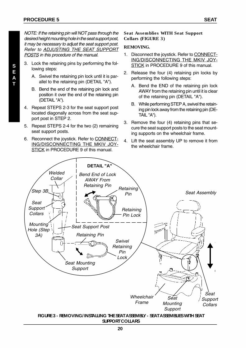
Seat Assemblies WITH Seat SupportCollars (FIGURE 3)
REMOVING.
1. Disconnect the joystick. Refer to CONNECT-ING/DISCONNECTING THE MKIV JOY-STICK in PROCEDURE 9 of this manual.
2. Release the four (4) retaining pin locks byperforming the following steps:
A. Bend the END of the retaining pin lockAWAY from the retaining pin until it is clearof the retaining pin (DETAIL "A").
B. While performing STEP A, swivel the retain-ing pin lock away from the retaining pin (DE-TAIL "A").
3. Remove the four (4) retaining pins that se-cure the seat support posts to the seat mount-ing supports on the wheelchair frame.
4. Lift the seat assembly UP to remove it fromthe wheelchair frame.
SeatMountingSupport
Seat Assembly
WheelchairFrame
RetainingPin Lock
Retaining Pin
FIGURE 3 - REMOVING/INSTALLING THE SEAT ASSEMBLY - SEAT ASSEMBLIES WITH SEATSUPPORT COLLARS
Bend End of LockAWAY FromRetaining Pin
SeatSupportCollars
SeatSupportCollars
WeldedCollar
RetainingPin
Seat MountingSupport
MountingHole (Step
3A)
Seat Support Post
DETAIL "A"
SwivelRetaining
PinLock
SEAT
SEATPROCEDURE 5
NOTE: If the retaining pin will NOT pass through thedesired height mounting hole in the seat support post,it may be necessary to adjust the seat support post.Refer to ADJUSTING THE SEAT SUPPORTPOSTS in this procedure of the manual.
3. Lock the retaining pins by performing the fol-lowing steps:
A. Swivel the retaining pin lock until it is par-allel to the retaining pin (DETAIL "A").
B. Bend the end of the retaining pin lock andposition it over the end of the retaining pin(DETAIL "A").
4. Repeat STEPS 2-3 for the seat support postlocated diagonally across from the seat sup-port post in STEP 2.
5. Repeat STEPS 2-4 for the two (2) remainingseat support posts.
6. Reconnect the joystick. Refer to CONNECT-ING/DISCONNECTING THE MKIV JOY-STICK in PROCEDURE 9 of this manual.
Step 3B

21
INSTALLING.
WARNINGEnsure that the four (4) retaining pins securingthe seat assembly to the wheelchair frameare properly engaged and locked. Other-wise, injury and/or damage may result.
1. Position the seat assembly onto the wheel-chair frame, making sure that the four (4) seatsupport posts align with the four (4) seatmounting supports on the wheelchair frame.
2. Allow the seat assembly to rest on the four(4) seat support collars.
3. Grasp one (1) retaining pin and position it sothat one (1) of the following occurs:
A. Pin passes through the mounting hole di-rectly below the seat support collars.
B. Pin passes through the mounting holes di-rectly below the welded collar of the seatassembly.
NOTE: If the retaining pin will NOT pass through thedesired height mounting hole in the seat support post,it may be necessary to adjust the seat support post.Refer to ADJUSTING THE SEAT SUPPORTPOSTS in this procedure of the manual.
4. Lock the retaining pin by performing the fol-lowing steps:
A. Swivel the retaining pin lock until it is par-allel to the retaining pin (DETAIL "A").
B. Bend the end of the retaining pin lock andposition it over the end of the retaining pin(DETAIL "A").
5. Repeat STEPS 1-4 for the four (4) remainingseat support posts.
6. Reconnect the joystick. Refer to CONNECT-ING/DISCONNECTING THE MKIV JOY-STICK in PROCEDURE 9 of this manual.
ADJUSTING THE SEAT HEIGHT
Seat Assemblies WITHOUT The SeatSupport Collars (FIGURE 4)
NOTE: The seat can be adjusted to three (3)height positions.
1. Release the four (4) retaining pins locks byperforming the following steps:
SEAT PROCEDURE 5
A. Bend the END of the retaining pin lockAWAY from the retaining pin until it is clearof the retaining pin (DETAIL "A").
B. While performing STEP A, swivel the retain-ing pin lock away from the retaining pin (DE-TAIL "A").
2. Lift up on the seat assembly to remove the weightof the seat assembly from the retaining pins.
CAUTIONWhen the four (4) retaining pins are re-moved the weight of the seat assemblyMUST be supported to prevent it from fall-ing onto the frame.
3. Remove the four (4) retaining pins that securethe seat support posts to the wheelchair frame.
4. Adjust the seat assembly to the desired height.
WARNINGEnsure that the four (4) retaining pins securingthe seat assembly to the wheelchair frameare properly engaged and locked. Other-wise, injury and/or damage may result.
NOTE: When installing the retaining pins, it neces-sary to support the weight of the seat assembly.
5. Grasp one (1) retaining pin and positioning it sothat it passes through the seat mounting supportAND through the desired mounting hole in theseat support post.
6. Lock the retaining pins by performing the fol-lowing steps:
A. Swivel the retaining pin lock until it is par-allel to the retaining pin (DETAIL "A").
B. Bend the end of the retaining pin lock andposition it over the end of the retaining pin(DETAIL "A").
NOTE: If the retaining pin will NOT pass through thedesired height mounting hole in the seat support post,it may be necessary to adjust the seat support post.Refer to ADJUSTING THE SEAT SUPPORTPOSTS in this procedure of the manual.
7. Repeat STEP 2 for the seat support post lo-cated DIAGONALLY across from the seat sup-port post in STEP 2.
8. Repeat STEPS 3-4 for the two (2) remainingseat support posts.
SEAT

22
SeatSupport
Post
SeatMountingSupport
SeatAssembly
WheelchairFrame
HeightMounting
Holes
FIGURE 4 - ADJUSTING THE SEAT HEIGHT - SEATASSEMBLIES WITHOUT SEAT SUPPORT COLLARS
Seat Assemblies WITH Seat SupportCollars (FIGURE 5)
1. Remove the seat assembly. Refer to REMOV-ING/INSTALLING THE SEAT ASSEMBLY inthis procedure of the manual.
2. Remove the four (4) seat support collars.Refer to REMOVING/INSTALLING THE SEATSUPPORT COLLARS in this procedure of themanual.
3. Perform one (1) of the following:
A. To position the seat assembly in the HIGH-EST position, align the mounting hole in theseat support collar with the MIDDLE mount-ing hole in the seat support post.
B. To position the seat assembly in the MIDDLEheight position, align the mounting hole inthe seat support collar with the TOP mount-ing hole in the seat support post.
C. To position the seat assembly in the LOW-EST height position, a seat support collar isNOT necessary. The welded seat supportof the seat assembly will rest on the seatmounting support of the wheelchair frame.
4. Install one (1) nut and bolt through mountinghole in the seat support collar and throughthe mounting hole in the seat support postdetermined in STEP 2. Securely tighten.
5. Repeat STEPS 2-5 for the three (3) remain-ing seat support posts.
6. Reinstall the seat assembly. Refer to REMOV-ING/INSTALLING THE SEAT ASSEMBLY inthis procedure of the manual.
SEAT
SEATPROCEDURE 5
Bend Endof LockAWAYFrom
RetainingPin
DETAIL "A"
Retaining Pin
Seat Support Post
Seat MountingSupport
Retaining Pin Lock
Retaining PinSwivel
RetainingPin
Lock

23
FRONT
RIGGINGS
HIGHEST POSITION
MIDDLE POSITION
LOWEST POSITION
Seat SupportCollar
MountingHole
MiddleMounting
Hole
Seat Support Post
Nut
Bolt
Seat SupportCollar
MountingHole
Top Mount-ing Hole
Seat Support Post
Nut
Bolt
No Seat SupportCollar Required
WeldedCollar
ADJUSTING THE SEAT SUPPORTPOSTS (FIGURE 6)
NOTE: If the retaining pin will NOT pass through theseat mounting support AND through one (1) of thethree (3) height mounting holes in the seat supportpost, perform the following steps:
1. Loosen, but DO NOT remove, the hex boltsecuring the seat support post to the seatstand.
2. Grasp the seat support post and rotate it untilthe height adjustment holes align with theholes in the seat mounting support.
3. Keeping the holes aligned, tighten the hex boltsecuring the seat support post to the seatstand.
4. If necessary, repeat STEPS 1-3 for the re-maining seat support posts.
FIGURE 6 - ADJUSTING THE SEAT SUPPORT POSTS
Hex Bolt
SeatSupport
Post
Seat Stand
Height AdjustmentHoles
Rotate toAlign Holes
SEAT
SEAT PROCEDURE 5
FIGURE 5 - ADJUSTING THE SEAT HEIGHT - SEATASSEMBLIES WITH SEAT SUPPORT COLLARS

24
SEAT
SEATPROCEDURE 5
ADJUSTING THE SEAT DEPTH(FIGURE 7 AND 8)
1. Remove the seat assembly. Refer to REMOV-ING/INSTALLING THE SEAT ASSEMBLY inthis procedure of the manual.
2. Remove the four (4) bolts, self-locking wash-ers and washers securing the seat assemblyto the seat pan (FIGURE 7).
3. Separate the seat assembly from the seat pan.
4. Refer to the chart in FIGURE 8 to determinethe correct mounting holes to achieve thedesired seat depth position (FIGURE 8).
NOTE: By using the three (3) sets of mounting holesin the seat assembly in combination with the mount-ing hole in the seat pan, three (3) seat depth positionscan be achieved (in one (1) inch increments).
5. Align the seat assembly mounting holes de-termined in STEP 4 with the seat pan mount-ing holes determined in STEP 4 (FIGURE 8).
6. Secure the seat assembly to the seat panusing the four (4) bolts, self-locking washersand washer. Securely tighten (FIGURE 7).
7. Reinstall the seat assembly. Refer to REMOV-ING/INSTALLING THE SEAT ASSEMBLY inthis procedure of the manual.
FIGURE 7 - ADJUSTING THE SEAT DEPTH
SeatAssembly
Seat Pan
Bolts
Self-Locking Washer
Washer
Mounting Holes
NOTE: The three (3)sets of mounting holesin the seat assembly arelocated UNDER the seatassembly.

25
Standard Seat Position
Moving Seat One (1) Inch Back
Moving Seat One (1) Inch Forward
Bottom Of Seat Assembly
Bottom Of Seat Pan
REMOVING/INSTALLING THESEAT POSITIONING STRAP(FIGURE 9)
NOTE: To remove, reverse the following procedure.
Installing
1. Remove the width adjustment knob that is lo-cated on the back of the seat frame.
2. Slide width adjustment knob through grom-met on seat positioning strap.
3. Reinstall width adjustment knob into seatframe.
4. Repeat STEPS 1-3 for opposite seat position-ing strap.
FIGURE 9 -REMOVING/INSTALLING THE SEATPOSITIONING STRAP
Seat PositioningStrap
Seat Frame
Grommet
Width AdjustmentKnob
FIGURE 8 - ADJUSTING THE SEAT DEPTH
Front
Back
Mounting Holes
Correct Mounting Holes
Bottom Of Seat Assembly
Bottom Of Seat Pan
Front
Back
Correct Mounting Holes
Back
Bottom Of Seat Assembly
Bottom Of Seat Pan
Front
Mounting Holes
Correct Mounting Holes
Mounting Holes
SEAT
SEAT PROCEDURE 5
26
This Procedure Includes the Following:
Folding/Unfolding the Back
Adjusting the Back Angle
Adjusting the Headrest
BACK
BACKPROCEDURE 6
WARNINGAfter ANY adjustments, repair or service and BE-FORE use, make sure that all attaching hardwareis tightened securely - otherwise injury or dam-age may result.
For the following procedures, make sure theON/OFF switch on the joystick is in the OFFposition.
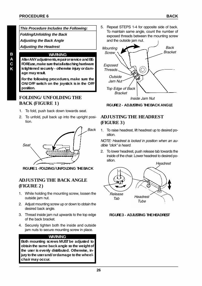
FOLDING/UNFOLDING THEBACK (FIGURE 1)
1. To fold, push back down towards seat.
2. To unfold, pull back up into the upright posi-tion.
FIGURE 1 -FOLDING/UNFOLDING THE BACK
Back
Seat
ADJUSTING THE BACK ANGLE(FIGURE 2)
1. While holding the mounting screw, loosen theoutside jam nut.
2. Adjust mounting screw up or down to obtain thedesired back angle.
3. Thread inside jam nut upwards to the top edgeof the back bracket.
4. Securely tighten both the inside and outsidejam nuts to secure mounting screw in place.
WARNINGBoth mounting screws MUST be adjusted toobtain the same back angle so the weight ofthe user is evenly distributed. Otherwise, in-jury to the user and/or damage to the wheel-chair may occur.
FIGURE 2 - ADJUSTING THE BACK ANGLE
OutsideJam Nut
MountingScrew
Inside Jam Nut
Top Edge of BackBracket
BackBracket
ADJUSTING THE HEADREST(FIGURE 3)
1. To raise headrest, lift headrest up to desired po-sition.
NOTE: Headrest is locked in position when an au-dible "click" is heard.
2. To lower headrest, push release tab towards theinside of the chair. Lower headrest to desired po-sition.
FIGURE 3 - ADJUSTING THE HEADREST
ReleaseTab
Headrest
HeadrestTube
ExposedThreads
5. Repeat STEPS 1-4 for opposite side of back.To maintain same angle, count the number ofexposed threads between the mounting screwand the outside jam nut.
27
This Procedure Includes the Following:
Removing/Installing/Adjusting the Footboard Assembly
Adjusting the Footboard Assembly Depth
FOOTBOARD
ASSEMBLY
FOOTBOARD ASSEMBLY PROCEDURE 7
WARNINGAfter ANY adjustments, repair or service and BE-FORE use, make sure that all attaching hard-ware is tightened securely - otherwise injury ordamage may result.
For the following procedures, make surethe ON/OFF switch on the joystick is in theOFF position.DO NOT stand on the flip-up footboard. Whengetting in or out of the wheelchair, make sure thatthe flip-up footboard is in the upward position .
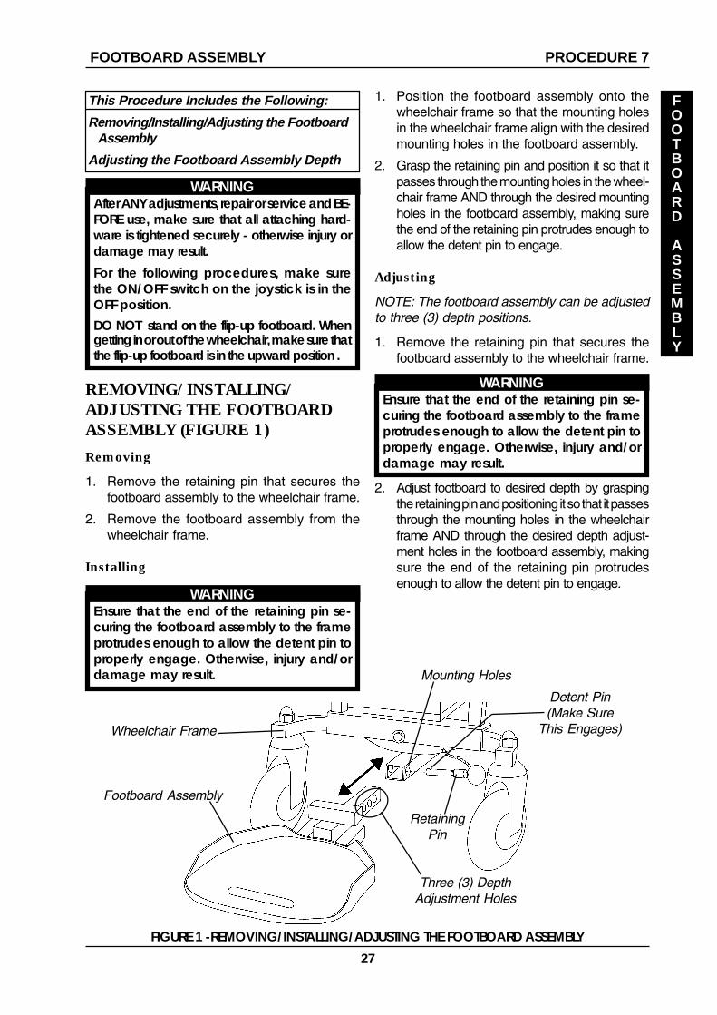
REMOVING/INSTALLING/ADJUSTING THE FOOTBOARDASSEMBLY (FIGURE 1)
Removing
1. Remove the retaining pin that secures thefootboard assembly to the wheelchair frame.
2. Remove the footboard assembly from thewheelchair frame.
Installing
WARNINGEnsure that the end of the retaining pin se-curing the footboard assembly to the frameprotrudes enough to allow the detent pin toproperly engage. Otherwise, injury and/ordamage may result.
1. Position the footboard assembly onto thewheelchair frame so that the mounting holesin the wheelchair frame align with the desiredmounting holes in the footboard assembly.
2. Grasp the retaining pin and position it so that itpasses through the mounting holes in the wheel-chair frame AND through the desired mountingholes in the footboard assembly, making surethe end of the retaining pin protrudes enough toallow the detent pin to engage.
Adjusting
NOTE: The footboard assembly can be adjustedto three (3) depth positions.
1. Remove the retaining pin that secures thefootboard assembly to the wheelchair frame.
WARNINGEnsure that the end of the retaining pin se-curing the footboard assembly to the frameprotrudes enough to allow the detent pin toproperly engage. Otherwise, injury and/ordamage may result.
2. Adjust footboard to desired depth by graspingthe retaining pin and positioning it so that it passesthrough the mounting holes in the wheelchairframe AND through the desired depth adjust-ment holes in the footboard assembly, makingsure the end of the retaining pin protrudesenough to allow the detent pin to engage.
FIGURE 1 -REMOVING/INSTALLING/ADJUSTING THE FOOTBOARD ASSEMBLY
Wheelchair Frame
RetainingPin
Footboard Assembly
Three (3) DepthAdjustment Holes
Mounting Holes
Detent Pin(Make Sure
This Engages)
28
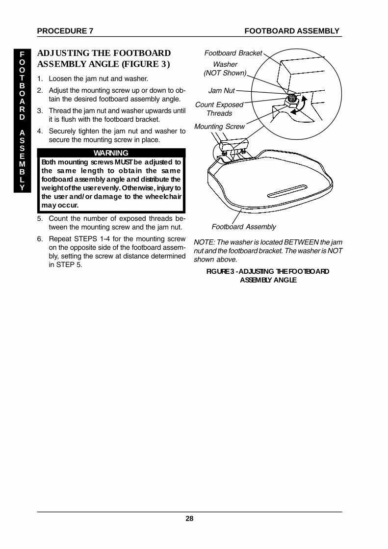
ADJUSTING THE FOOTBOARDASSEMBLY ANGLE (FIGURE 3)
1. Loosen the jam nut and washer.
2. Adjust the mounting screw up or down to ob-tain the desired footboard assembly angle.
3. Thread the jam nut and washer upwards untilit is flush with the footboard bracket.
4. Securely tighten the jam nut and washer tosecure the mounting screw in place.
WARNINGBoth mounting screws MUST be adjusted tothe same length to obtain the samefootboard assembly angle and distribute theweight of the user evenly. Otherwise, injury tothe user and/or damage to the wheelchairmay occur.
5. Count the number of exposed threads be-tween the mounting screw and the jam nut.
6. Repeat STEPS 1-4 for the mounting screwon the opposite side of the footboard assem-bly, setting the screw at distance determinedin STEP 5.
FOOTBOARD ASSEMBLYPROCEDURE 7
FOOTBOARD
ASSEMBLY
FIGURE 3 -ADJUSTING THE FOOTBOARDASSEMBLY ANGLE
Jam Nut
Mounting Screw
Footboard Assembly
Footboard Bracket
Count ExposedThreads
NOTE: The washer is located BETWEEN the jamnut and the footboard bracket. The washer is NOTshown above.
Washer(NOT Shown)

29
This Procedure Includes the Following:
Replacing the Foam Filled Tires onto the Wheel Rim
Removing/Installing the Shroud
Engaging/Disengaging Motor Locks
Removing/Installing the Axle Shroud Covers
Replacing the Front/Rear Caster Assemblies
SHROUD/WHEELS PROCEDURE 8
WARNINGAfter ANY adjustments, repair or service and BE-FORE use, make sure that all attaching hard-ware is tightened securely - otherwise injury ordamage may result.
For the following procedures, make sure theON/OFF switch on the joystick is in the OFFposition.
REPLACING THE FOAM FILLEDTIRES ONTO THE WHEEL RIM
WARNINGThis procedure MUST be performed by aqualified technician.
NOTE: During initial use of the wheelchair, the usermay experience flat spots on the wheels. Flat spotswill vanish with continued use of the wheelchair.
REMOVING/INSTALLING THESHROUD (FIGURE 1)
Removing
1. Disconnect the joystick. Refer to CONNECT-ING/DISCONNECTING THE MKIV JOY-STICK in PROCEDURE 9 of the manual.
2. Remove the seat assembly. Refer to REMOV-ING/INSTALLING THE SEAT ASSEMBLY inPROCEDURE 4 of the manual.
3. Grasp the charger port cover and remove itfrom the charger port.
4. Lift the shroud off of the wheelchair frame.
Installing
1. Align the four (4) hook and loop fasteners on theunderside of the shroud with the four (4) hookand loop fasteners on the wheelchair frame.
2. Firmly push the shroud onto the wheelchairframe, making sure the hook and loop fas-teners meet.
SHROUD/
WHEELS
FIGURE 1 - REMOVING/INSTALLING THE SHROUD
Shroud
WheelchairFrame
ENGAGING/DISENGAGINGMOTOR LOCKS (FIGURE 2)
WARNINGDO NOT engage or disengage the motorlocks until the ON/OFF switch on the joy-stick is in the OFF position.
CAUTIONEnsure both motor locks are fully engagedBEFORE driving the wheelchair
NOTE: The motor lock disengagement/engage-ment allows freewheeling OR joystick controlledoperation. Freewheeling allows an attendant tomaneuver the wheelchair WITHOUT power.
1. Locate the motor lock handles on the motors.
2. Perform one (1) of the following:
NOTE: Hook and loop fasteners under shroudNOT shown for clarity
Hook andLoop
Fasteners
Hook andLoop
Fasteners
3. Grasp the charger port cover and position itin the charger port.
4. Reinstall the seat. Refer to REMOVING/IN-STALLING THE SEAT ASSEMBLY in PRO-CEDURE 4 of the manual.
5. Reconnect the joystick. Refer to CONNECT-ING/DISCONNECTING THE MKIV JOY-STICK in PROCEDURE 9 of the manual.
ChargerPort
Cover

30
B. To ENGAGE the motor locks -
Grasp the motor lock handle connectedto the RIGHT motor and position it inthe DOWN position.
Grasp the motor lock handle connectedto the LEFT motor and position it in theUP position.
A. To DISENGAGE the motor locks -
Grasp the motor lock handle connectedto the RIGHT motor and position it inthe UP position.
Grasp the motor lock handle connectedto the LEFT motor and position it in theDOWN position.
SHROUD/WHEELSPROCEDURE 8
SHROUD/
WHEELS
LeftMotor
NOTE: To ENGAGE/DISENGAGE the motor lock for the RIGHT motor, position the motor lockhandle in the OPPOSITE position shown above.
Push handle DOWN toDISENGAGE motor lock.
Push handle UP toENGAGE motor lock.
REAR OF WHEELCHAIR
FIGURE 2 - ENGAGING/DISENGAGING MOTOR LOCKS
LeftMotor

31
REPLACING THE FRONT/REARCASTER ASSEMBLIES (FIGURE 4)
NOTE: Front and rear caster assemblies are re-placed in the same manner.
NOTE: When replacing the front/rear caster as-semblies, it is necessary to brace the caster as-semblies to prevent the wheel from spinning.
1. Remove the fork or stem cover from the wheel-chair frame. Refer to REMOVING/INSTALL-ING THE FORK AND STEM COVERS in thisprocedure of the manual.
2. Hold the caster assembly with one (1) handand loosen the cap nut with the other handusing a crescent wrench.
3. Remove the EXISTING cap nut securing the EX-ISTING caster assembly to the wheelchair frame.
4. Remove the EXISTING caster assembly fromthe wheelchair frame.
5. Position the NEW caster assembly in themounting hole in the wheelchair frame.
6. Secure the NEW caster assembly to thewheelchair frame with the NEW cap nut. Se-curely tighten.
7. If necessary, repeat STEPS 1-4 for the re-maining three (3) caster assemblies.
FIGURE 4 - REPLACING THE FRONT/REARCASTER ASSEMBLIES
Cap Nut
CasterAssembly
WheelchairFrame
MountingHole
REMOVING/INSTALLING THE AXLESHROUD COVERS (FIGURE 3)
NOTE: The front and rear axle shroud covers areremoved/installed in the same manner.
NOTE: To install the front and rear axle shroudcovers, reverse the following steps.
Removing
1. If necessary, remove the shroud. Refer toREMOVING/INSTALLING THE SHROUD inPROCEDURE 7 of the manual.
2. Remove the mounting screw securing the axleshroud cover to the wheelchair frame.
3. Remove the axle shroud cover from the wheel-chair frame.
FIGURE 3 - REMOVING/INSTALLING THE FORKAND STEM COVERS
CasterAssembly
WheelchairFrame
Mounting Screw
FrontAxle
ShroudCover
SHROUD/WHEELS PROCEDURE 8
SHROUD/
WHEELS
NOTE: Rear axle shroud cover NOT shown.

32
This Procedure Includes the Following:
Removing/Installing Batteries without Removing Cables
Connecting/Disconnecting Battery Cables
Connecting/Disconnecting Circuit Breaker Cables
Replacing Batteries
When to Charge Batteries
Charging Batteries
Battery Charger Operation
WARNINGFor the following procedures, make sure theON/OFF switch on the joystick is in the OFFposition.
The use of rubber gloves and safety glasses isrecommended when working with batteries.
Invacare strongly recommends that batteryinstallation and battery replacement alwaysbe done by a qualified technician.
After ANY adjustments, repair or service and BE-FORE use, make sure that all attaching hard-ware is tightened securely - otherwise injury ordamage may result.
CAUTIONThe POSITIVE (+) RED battery cable MUST con-nect to the battery clamp of the POSITIVE(+) battery terminal/post, otherwise seriousdamage will occur to the electrical system.
REMOVING/INSTALLINGBATTERIES WITHOUTREMOVING CABLES (FIGURE 1)
NOTE: To install the batteries without removingcables, reverse the following steps.
Removing
WARNINGAlways use a battery lifting strap when lift-ing a battery. It is the most convenientmethod and assures that the battery acidwill not spill. It also helps to prolong the lifeof the battery.
DO NOT tip the batteries. Keep the batter-ies in an upright position.
NOTE: If there is battery acid on the bottom orthe sides of the battery(ies) or on the frame of thewheelchair, apply baking soda to these areas toneutralize the battery acid. Before reinstalling theNEW or EXISTING batteries, clean the bakingsoda from the battery(ies).
1. Disconnect the joystick. Refer to DISCON-NECTING/CONNECTING THE MKIV JOY-STICK in PROCEDURE 9 of the manual.
2. Remove the seat assembly. Refer to REMOV-ING/INSTALLING THE SEAT ASSEMBLY inPROCEDURE 4 of the manual.
3. Remove the shroud. Refer to REMOVING/INSTALLING THE SHROUD in PROCE-DURE 7 of the manual.
4. Separate the FRONT frame assembly fromthe REAR frame assembly. Refer to TRANS-PORTING THE WHEELCHAIR in PROCE-DURE 10 of the manual.
5. Disconnect the battery fastening strap and pullit through the retaining ring.
CAUTIONBefore removing the batteries, it is neces-sary to disconnect the FRONT battery fromthe REAR battery. Otherwise, damage tothe batteries may occur.
BATTERIES
BATTERIESPROCEDURE 9
FIGURE 1 - REMOVING/INSTALLING THEBATTERIES WITH CABLES
BatteryFastening
Strap
RetainingRing
Front Battery
Rear Battery
Rear Frame Assembly
Disconnect FRONT Batteryfrom REAR Battery
+-
+-

33
6. Disconnect the FRONT battery from theREAR battery. Refer to CONNECTING/DIS-CONNECTING BATTERY CABLES in thisprocedure of the manual.
7. Remove both batteries with cables from therear frame assembly.
CONNECTING/DISCONNECTINGBATTERY CABLES (FIGURE 2)
NOTE: To disconnect the battery cables, reversethe following steps.
Connecting
WARNINGNEVER allow any of your tools and/or batterycable(s) to contact BOTH battery terminal(s)/post(s) at the same time. An electrical short mayoccur and serious personal injury or damagemay occur.
The use of rubber gloves and safety glasses isrecommended when working with batteries.
CAUTIONThe POSITIVE (+) RED battery cable MUST con-nect to the battery clamp of the POSITIVE(+) battery terminal/post, otherwise seriousdamage will occur to the electrical system.
1. Install the RED battery terminal cap onto theRED battery cable.
2. Install the BLACK battery terminal cap ontothe BLACK battery cable.
3. Connect battery cable(s) to battery(ies)terminal(s)/post(s) as follows:
A. NEGATIVE (-) BLACK battery cable toNEGATIVE (-) battery terminal/post on theREAR battery.
B. POSITIVE (+) RED battery cable to POSI-TIVE (+) battery terminal/post on theFRONT battery.
4. Secure the battery cable(s)/ring terminal(s) tothe battery terminal(s)/post(s), BLACK toNEGATIVE (-) and RED to POSITIVE (+), withthe provided hex flange screw and hex flangelocknut. Securely tighten.
5. Verify all battery cable(s)/ring terminal(s) are cor-rectly installed and securely tightened.
6. Slide terminal cap(s) down battery cable(s) andonto battery terminals (DETAIL "A").
BATTERIES
BATTERIES PROCEDURE 9
BLACK BatteryTerminal Cap
(STEPS 2 and 3A)
RED BatteryTerminal Cap
(STEP 1)
REAR U1Battery(STEP
3A)
Front U1Battery
Negative (-)BLACKBattery
Terminal/Post (STEP
3A)
Positive (+) REDBattery Terminal/Post
(STEP 3B)
HexFlangeLocknut
Hex FlangeScrew
Battery Terminal/Post
Cable/RingTerminal
FIGURE 2 - CONNECTING/DISCONNECTINGBATTERY CABLES
DETAIL "A"
BatteryTerminal Cap
(STEPS 1and 2)
Negative (-) BLACKBattery Cable
(STEPS 2 and 3A)
Positive (+) REDBattery Cable
(STEPS 1 and 3B)

34
BATTERIES
BATTERIESPROCEDURE 9
7. Install the batteries with cables into the wheel-chair. Refer to REMOVING/INSTALLING THEBATTERIES WITH CABLES in this procedureof the manual.
CAUTIONALWAYS charge new batteries before ini-tial use or battery life will be reduced.
8. If necessary, charge the batteries. Refer toCHARGING THE BATTERIES in this proce-dure of the manual.
CONNECTING/DISCONNECTINGCIRCUIT BREAKER CABLES(FIGURE 3)
NOTE: To disconnect the circuit breaker cables,reverse the following steps.
Connecting
WARNINGNEVER allow any of your tools and/or batterycable(s) to contact BOTH battery terminal(s)/post(s) at the same time. An electrical short mayoccur and serious personal injury or damagemay occur.
The use of rubber gloves and safety glasses isrecommended when working with batteries.
CAUTIONThe POSITIVE (+) RED battery cable MUST con-nect to the battery clamp of the POSITIVE(+) battery terminal/post, otherwise seriousdamage will occur to the electrical system.
1. Install the RED battery terminal cap onto theRED circuit breaker cable.
2. Install the BLACK battery terminal cap ontothe BLACK circuit breaker cable.
3. Connect circuit breaker cable(s) to battery(ies)terminal(s)/post(s) as follows (FIGURE 2):
A. NEGATIVE (-) BLACK circuit breakercable to NEGATIVE (-) battery terminal/post on the FRONT battery.
B. POSITIVE (+) RED circuit breaker cableto POSITIVE (+) battery terminal/post onthe REAR battery.
4. Secure the circuit breaker cable(s)/ringterminal(s) to the battery terminal(s)/post(s),BLACK to NEGATIVE (-) and RED to POSI-TIVE (+), with the provided hex flange screwand hex flange locknut. Securely tighten (FIG-URE 2).
5. Verify all circuit breaker cable(s)/ring terminal(s)are correctly installed and securely tightened.
HexFlangeLocknut
HexFlangeScrew
Negative(-)Battery
Terminal/Post
Cable/RingTerminal
Black BatteryTerminal Cap
Negative(-)BlackCircuit
BreakerCable
HexFlangeLocknut
HexFlangeScrew
Positive(+)Battery
Terminal/Post
Cable/RingTerminal
Red BatteryTerminal Cap
Positive(+)RedCircuit
BreakerCable
Front U1 Battery+
-
-+
Rear U1 Battery
FIGURE 3 - CONNECTING/DISCONNECTING CIRCUIT BREAKER CABLES

35
6. Slide terminal cap(s) down circuit breaker cable(s)and onto battery terminals (FIGURE 3).
7. Install the batteries with cables into the wheel-chair. Refer to REMOVING/INSTALLING THEBATTERIES WITH CABLES in this procedureof the manual.
CAUTIONALWAYS charge new batteries before ini-tial use or battery life will be reduced.
8. If necessary, charge the batteries. Refer toCHARGING THE BATTERIES in this proce-dure of the manual.
REPLACING BATTERIES
WARNINGMost batteries are not sold with instructions.However, warnings are frequently noted onthe cell caps. Read them carefully, otherwiseinjury or damage can occur.
NOTE: Invacare recommends that both batteries bereplaced if one (1) battery is defective.
Recommended Battery Types
WARNINGThe warranty and performance specificationscontained in this manual are based on the useof deep cycle gel cell or sealed lead acidbatteries. Invacare strongly recommends theiruse as the power source for this unit.
CAUTIONFailure to use the correct battery size and/orvoltage may cause damage to your wheel-chair and give you unsatisfactory perfor-mance.
NOTE: The recommended battery type is U1 deepcycle.
1. Remove the EXISTING batteries with cables.Refer to REMOVING/INSTALLING THE BAT-TERIES WITH CABLES in this procedure ofthe manual.
2. Disconnect the battery cables. Refer to CON-NECTING/DISCONNECTING BATTERYCABLES in this procedure of the manual.
3. Disconnect the circuit breaker cables. Referto CONNECTING/DISCONNECTING CIR-CUIT BREAKER CABLES in this procedureof the manual.
4. Clean the NEW battery terminals. Refer toCLEANING BATTERY TERMINALS in thisprocedure of the manual.
5. Reconnect the EXISTING battery cables tothe NEW batteries. Refer to CONNECTING/DISCONNECTING BATTERY CABLES in thisprocedure of the manual.
6. Reconnect the EXISTING circuit breaker cablesto the NEW batteries. Refer to CONNECTING/DISCONNECTING CIRCUIT BREAKERCABLES in this procedure of the manual.
7. Install the NEW batteries with cables. Refer toREMOVING/INSTALLING THE BATTERIESWITH CABLES in this procedure of the manual.
Cleaning Battery Terminals
WARNINGDO NOT allow the liquid in the battery to comein contact with skin, clothes or other possessions.It is a form of acid and harmful or damagingburns may result. Should the liquid touch yourskin, wash the area immediately and thoroughlywith cool water. In serious cases or if eye contactis made, seek medical attention IMMEDIATELY.NEVER smoke or strike a match near batter-ies. If the caps of the battery cells are re-moved, NEVER look directly into them whilecharging batteries.
1. Examine battery clamps and terminals for corrosion.
2. Slide the terminal cap up the wire to exposethe battery terminal.
3. Disconnect the battery cable from one (1) bat-tery terminal/post. Refer to CONNECTING/DISCONNECTING BATTERY CABLES in thisprocedure of the manual.
4. Clean the terminals and inside the battery clampsby using a battery cleaning tool, wire brush, ormedium grade sand paper.
NOTE: When done, these areas should be shiny, notdull.
5. Carefully dust off all metal particles.
6. Slide the terminal cap back down the wire tocover the battery terminal.
7. Reconnect the battery cable to the battery ter-minal/post. Refer to CONNECTING/DISCON-NECTING BATTERY CABLES in this proce-dure of the manual.
8. If necessary, repeat STEPS 1-7 for the re-maining battery terminal/post.
BATTERIES
BATTERIES PROCEDURE 9

36
WHEN TO CHARGE BATTERIES(FIGURE 4)It is advantageous to recharge daily rather than onlywhen necessary. In fact, a battery’s life is extended ifthe charge level is maintained well above a low condi-tion.
The range per battery charge using recommendedbatteries should be approximately 5 to 9 hours oftypical operation. Extensive use on inclines or theage of the batteries may substantially reduce percharge mileage.
MKIV RII Joystick
BATTERY DISCHARGE INDICATOR (BDI) is locatedat the front of the joystick housing and provides infor-mation on the remaining charge in the batteries. AtFULL charge the BDI will be GREEN. As the batterybecomes discharged, the BDI indicator will turn AM-BER (YELLOW), then RED and finally FLASHINGRED. If the BDI is FLASHING RED, the user shouldcharge the batteries as soon as possible.
NOTE: Accurate readings are displayed when in neu-tral.
Battery DischargeIndicator (BDI)
FIGURE 4 - WHEN TO CHARGE BATTERIES
CHARGING BATTERIES
WARNINGNEVER attempt to recharge the batteriesby attaching cables directly to the batteryterminals.
DO NOT attempt to recharge the batteries andoperate the wheelchair at the same time.
DO NOT attempt to recharge the batterieswhen the wheelchair has been exposedto ANY type of moisture.
DO NOT attempt to recharge the batterieswhen the wheelchair is outside.
DO NOT sit in the wheelchair while recharg-ing the batteries.
DO NOT attempt to recharge the batteriesusing BOTH the on-board battery charger ANDan independent battery charger (pluggedinto the joystick charger port) at the SAME time.Doing so will reduce the life of the batteries.
READ and CAREFULLY follow the individualinstructions for each charger (supplied orpurchased). If charging instructions are notsupplied, consult a qualified technician forproper procedures.
CAUTIONNew batteries MUST be fully charged priorto initial use of the wheelchair.
ALWAYS charge new batteries before ini-tial use or battery life will be reduced.
As a general rule, you should recharge yourbatteries as frequently as possible to assure thelongest possible life and to minimize requiredcharging time. Plan to recharge them whenyou do not anticipate using the wheelchair.
There are some basic concepts which will helpyou understand this automatic process:
The amount of electrical current drawn within a given timeto charge a battery is called “charge rate”. If, due to usage,the charge stored in the battery is low, the charge rate ishigh. As a charge builds up, the charge rate is reduced,and the battery charger rate decreases to a "trickle charge".
NOTE: If the batteries need to be charged more of-ten or take longer to charge than normal, they mayneed to be replaced. Contact a qualified technician.
NOTE: The batteries can be charged using theon-board battery charger OR by plugging an in-dependent battery charger into the port locatedon the front of the MKIV joystick.
BATTERIES
BATTERIESPROCEDURE 9
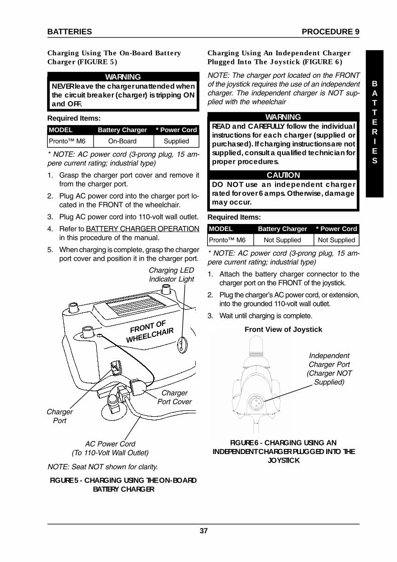
37
BATTERIES
PROCEDURE 9
FIGURE 5 - CHARGING USING THE ON-BOARDBATTERY CHARGER
AC Power Cord(To 110-Volt Wall Outlet)
FRONT OF
WHEELCHAIR
Charging Using An Independent ChargerPlugged Into The Joystick (FIGURE 6)
NOTE: The charger port located on the FRONTof the joystick requires the use of an independentcharger. The independent charger is NOT sup-plied with the wheelchair
WARNINGREAD and CAREFULLY follow the individualinstructions for each charger (supplied orpurchased). If charging instructions are notsupplied, consult a qualified technician forproper procedures.
CAUTIONDO NOT use an independent chargerrated for over 6 amps. Otherwise, damagemay occur.
Required Items:
MODEL Battery Charger * Power Cord
Pronto™ M6 On-Board Supplied
* NOTE: AC power cord (3-prong plug, 15 am-pere current rating; industrial type)
1. Grasp the charger port cover and remove itfrom the charger port.
2. Plug AC power cord into the charger port lo-cated in the FRONT of the wheelchair.
3. Plug AC power cord into 110-volt wall outlet.
4. Refer to BATTERY CHARGER OPERATIONin this procedure of the manual.
5. When charging is complete, grasp the chargerport cover and position it in the charger port.
ChargerPort
Front View of Joystick
IndependentCharger Port
(Charger NOTSupplied)
FIGURE 6 - CHARGING USING ANINDEPENDENT CHARGER PLUGGED INTO THE
JOYSTICK
BATTERIES
NOTE: Seat NOT shown for clarity.
Required Items:
MODEL Battery Charger * Power Cord
Pronto™ M6 Not Supplied Not Supplied
* NOTE: AC power cord (3-prong plug, 15 am-pere current rating; industrial type)
1. Attach the battery charger connector to thecharger port on the FRONT of the joystick.
2. Plug the charger’s AC power cord, or extension,into the grounded 110-volt wall outlet.
3. Wait until charging is complete.
Charging Using The On-Board BatteryCharger (FIGURE 5)
WARNINGNEVER leave the charger unattended whenthe circuit breaker (charger) is tripping ONand OFF.
Charging LEDIndicator Light
ChargerPort Cover

38
ON/OFF INDICATOR STATUS
SOLID RED CHARGER ON
"BLINKING" RED ABNORMAL
LED "OFF" CHARGER OFF
CHARGING INDICATOR STATUS
"BLINKING" GREEN CHARGING
SOLID GREEN FULLY CHARGED
LED "OFF" CHARGERDISCONNECTED
BATTERIES
BATTERIESPROCEDURE 9
BATTERY CHARGER OPERATION
WARNINGREAD and CAREFULLY follow the individualinstructions for each charger (supplied orpurchased). If charging instructions are notsupplied, consult a qualified technician forproper procedures.
On-Board Battery Charger (FIGURE 7)
1. Remove the shroud. Refer to REMOVING/INSTALLING THE SHROUD in PROCE-DURE 7 of this manual.
2. Locate the switch on the BACK of the batterycharger and confirm it is set to 115 volts andperform one (1) of the following:
Switch set to 115 volts -A. Continue onto STEP 3.
Switch NOT set to 115 volts -B. Peel back the plastic cover that is positioned
over the switch (DETAIL "A").
C. Flip the switch to the upward position so it isset to 115 volts (DETAIL "A").
D. Reposition the plastic cover over the switch(DETAIL "A").
F. Continue onto to STEP 3.
3. Reinstall the shroud. Refer to REMOVING/INSTALLING THE SHROUD in PROCE-DURE 7 of this manual.
NOTE: The ON/OFF LED indicator light AND thecharger LED indicator light are located in the FRONTof the wheelchair next to the charger port.
4. The ON/OFF LED indicator will illuminate solidRED indicating that the charger is ON.
5. If the ON/OFF LED indicator is "BLINKING" RED,this is abnormal. Unplug AC power cord from theon-board battery charger and wall outlet. ContactInvacare at the number listed on the back page.
6. When the ON/OFF LED indicator light is OFF,charger is OFF.
7. When the CHARGE LED indicator light is "BLINK-ING" GREEN, the batteries are charging.
8. When the CHARGE LED indicator light is solidGREEN, the batteries are FULLY charged (or asfully charged as their condition will allow). At thispoint, the charger automatically stops charging.
FIGURE 7 - BATTERY CHARGER OPERATION
ON/OFFLED
IndicatorLight
NOTE: Seat NOT shown for clarity.
FRONT OF
WHEELCHAIR
Charging Port
ChargingLED
IndicatorLight
6. If the charger is on and the CHARGE LED indi-cator light is OFF, the charger is disconnected.Check that all connections are secure. IfCHARGE LED indicator light is still OFF, unplugAC power cord from the on-board battery chargerand wall outlet. Contact Invacare at the numberlisted on the back page.
NOTE: The wheelchair is designed with an electricallockout to prevent it from being driven while thecharger is plugged in to an outlet.
DETAIL "A"
Back ofBatteryCharger
PlasticCover
(PeeledBack)
Switch(flipped toupwardposition)115V

39
Independent Battery Charger
NOTE: The charger port located on the FRONTof the joystick requires the use of an independentcharger. The independent charger is NOT sup-plied with the wheelchair
WARNINGREAD and CAREFULLY follow the individualinstructions for each charger (supplied orpurchased). If charging instructions are notsupplied, consult a qualified technician forproper procedures.
CAUTIONDO NOT use an independent chargerrated for over 6 amps. Otherwise, damagemay occur.
REMOVING/INSTALLING ON-BOARD BATTERY CHARGER
WARNINGThis procedure MUST be performed by aqualified technician.
BATTERIES
PROCEDURE 9BATTERIES

40
ELECTRONICSPROCEDURE 10
This Procedure Includes the Following:
Retracting the MKIV Joystick
Repositioning the MKIV Joystick
Disconnecting/Connecting the MKIV Joystick
WARNINGAfter ANY adjustments, repair or service and BE-FORE use, make sure that all attaching hard-ware is tightened securely - otherwise injury ordamage may result.
For the following procedures, make sure theON/OFF switch on the joystick is in the OFFposition.
RETRACTING THE MKIVJOYSTICK (FIGURE 1)NOTE: The MKIV joystick can be retracted from it'sposition in front of the armrest and maneuvered sothat it is parallel to the armrest. When the MKIV joy-stick is parallel to the armrest, the wheelchair can beSLOWLY maneuvered to allow the end-user to po-sition the wheelchair at a table, desk, etc...
WARNINGPositioning the joystick PARALLEL to the arm-rest allows the wheelchair to be SLOWLYmaneuvered up to a desk/table. ANY otherwheelchair operation is to be performed withthe joystick secured with the retaining pin inthe FRONTAL position - otherwise injury or dam-age may result.
NOTE: To return the MKIV joystick to the frontalposition, reverse the following steps.
1. Position the wheelchair so that it is close to andfacing the desk, table, etc...
2. Pull the retaining pin securing the joystick in thefrontal position.
3. Grasp the joystick and push it OUTWARD andBACK, until the joystick is parallel to the armrest.
4. Slowly maneuver the wheelchair up to thedesk, table, etc...
FIGURE 1 - RETRACTING THE MKIV JOYSTICK
MKIV JOYSTICK IN FRONTAL POSITION
MKIV JOYSTICK PARALLEL TO ARMREST
RetainingPin
Joystick
Armrest
JoystickArmrest
Push JoystickOUTWARD andBACK to retract it
ELECTRONICS

41
ELECTRONICS
ELECTRONICS PROCEDURE 10
DISCONNECTING/CONNECTINGTHE MKIV JOYSTICK (FIGURE 2)Disconnecting
1. Loosen the thumb screws on the connectorfor the joystick.
2. Disconnect the joystick connector from thecontroller connecter.
Connecting
1. Align the joystick connector with the control-ler connecter.
2. Secure the joystick connector to the control-ler connector using the thumb screws on thecontroller connector.
WARNINGThe excess joystick cable MUST be coiled,tie wrapped and positioned on TOP of theshroud - otherwise injury or damage mayresult.
3. Coil any slack in the joystick cable and tie wrapit together (DETAIL "A").
4. Position the coiled joystick cable on TOP ofthe shroud (DETAIL "A")
FIGURE 2 - DISCONNECTING/CONNECTINGTHE MKIV JOYSTICK
REPOSITIONING THE MKIVJOYSTICK
WARNINGThis procedure MUST be performed by aqualified technician.
NOTE: The MKIV joystick is factory installed on theside specified by the end user when ordering the wheel-chair. To reposition the MKIV joystick onto the oppositeside of the wheelchair, contact a qualified technician.
Joystick
ThumbScrews
JoystickConnector
ControllerConnector
Shroud
CoiledJoystickCable
Tie Wrap
DETAIL A

42
TRANSPORT
TRANSPORTPROCEDURE 11
This Procedure Includes the Following:
Transporting the Wheelchair
WARNINGAfter ANY adjustments, repair or service and BE-FORE use, make sure that all attaching hard-ware is tightened securely - otherwise injury ordamage may result.
For the following procedures, make sure theON/OFF switch on the joystick is in the OFFposition.
TRANSPORTING THEWHEELCHAIR (FIGURES 1 AND 2)
Disassembling The Wheelchair
NOTE: To reassemble the wheelchair, reverse thefollowing steps.
1. Disconnect the joystick. Refer to DISCON-NECTING/CONNECTING THE MKIV JOY-STICK in PROCEDURE 9 of the manual.
2. Fold down the back. Refer to FOLDING/UN-FOLDING THE BACK in PROCEDURE 5 ofthe manual.
3. Remove the seat. Refer to REMOVING/IN-STALLING THE SEAT in PROCEDURE 4 ofthe manual.
4. Remove the shroud. Refer to REMOVING/INSTALLING THE SHROUD in PROCE-DURE 7 of the manual.
NOTE: The motor connectors are located UN-DERNEATH the FRONT frame assembly.
WARNINGWhen reconnecting the motors, be sure themotor wires are routed toward the INSIDEof the wheelchair frame - otherwise, injuryor damage may result.
5. Disconnect the LEFT motor connector fromthe controller connector.
6. Repeat STEP 5 for the RIGHT motor connector.
FIGURE 1 - TRANSPORTING THE WHEELCHAIR
Left MotorConnector
RedCable
BlackCable
ControllerConnector
Circuit Breaker
RearFrame
Assembly
Front FrameAssembly
STEP 5 AND 6
STEP 8
STEP 9 AND 10
BendLockOut
RetainingPin Lock
RetainingPin
STEP 7ControllerConnector
BatteryConnector
Left Motor WireRouted (TowardInside Of Frame)
Wheelchair Frame
DETAIL "A"

43
TRANSPORT
TRANSPORT PROCEDURE 11
Rear FrameAssembly
Front FrameAssembly
STEP 11
DISASSEMBLED VIEW
Shroud
Seat
7. Disconnect the battery connector from thecontroller connector.
8. Disconnect the RED and BLACK circuitbreaker cables from the circuit breaker.
WARNINGWhen reassembling the wheelchair, ensure theretaining pins securing the frame assembliestogether are properly engaged and locked.Otherwise, injury and/or damage may result.
9. Release the two (2) retaining pins locks byperforming the following steps:
A. Bend the END of the retaining pin lockAWAY from the retaining pin until it is clearof the retaining pin (DETAIL "A").
B. While performing STEP A, swivel the re-taining pin lock away from the retaining pin(DETAIL "A").
10. Remove the two (2) retaining pin that secures therear frame assembly to the front frame assembly.
11. Separate the front frame assembly from therear frame assembly.
12. Remove the batteries with cables. Refer to RE-MOVING/INSTALLING THE BATTERIES WITHCABLES in PROCEDURE 8 of the manual.
Front FrameAssembly
BatteriesWith
Cables
Rear FrameAssembly
FIGURE 2 - TRANSPORTING THE WHEELCHAIR

44
FIGURE 1 - REMOVING/INSTALLING THE CRUTCH/CANE HOLDER
Crutch/CaneHolder
AccessoryTube
MountingScrew
Base
Hook
Seat
REMOVING/INSTALLING THESAFETY FLAG (FIGURE 2)
NOTE: To remove, reverse the following proce-dure.
WARNINGThe installation of the safety flag onto the backof the wheelchair seat significantly increasesthe length of the wheelchair. When turningthe wheelchair or swiveling the wheelchairseat, it is important to take note of this in-creased length - otherwise, injury and/or dam-age to the surrounding property may result.
Installing
1. Install the bracket into the accessory tube lo-cated on the back of the seat.
2. Install mounting screw to secure the bracketin place. Securely tighten.
3. Install safety flag into bracket.
FIGURE 2 - REMOVING/INSTALLING THE SAFETYFLAG
AccessoryTube
MountingScrewBracket
SafetyFlag
Seat
This Procedure Includes the Following:
Removing/Installing the Crutch/Cane Holder
Removing/Installing The Safety Flag
WARNINGAfter ANY adjustments, repair or service and BE-FORE use, make sure that all attaching hard-ware is tightened securely - otherwise injury ordamage may result.
For the following procedures, make sure theON/OFF switch on the joystick is in the OFFposition.
REMOVING/INSTALLING THECRUTCH/CANE HOLDER(FIGURE 1)
NOTE: To remove, reverse the following proce-dure.
WARNINGThe installation of the crutch/cane holder ontothe back of the wheelchair seat significantlyincreases the length of the wheelchair. Whenturning the wheelchair or swiveling thewheelchair seat, it is important to take noteof this increased length - otherwise, injury and/or damage to the surrounding property mayresult.
Installing
1. Install the crutch/cane holder into the acces-sory tube located on the back of the seat.
2. Install mounting screw to secure the crutch/cane holder in place. Securely tighten.
3. Align slot on base with hook on crutch/caneholder and slide base down into position.
OPTIONSPROCEDURE 12
SlotOPTIONS

45
NOTES____________________________________________________________________________________________________________________________________________________________________________________________________________________________________________________________________________________________________________________________________________________________________________________________________________________________________________________________________________________________________________________________________________________________________________________________________________________________________________________________________________________________________________________________________________________________________________________________________________________________________________________________________________________________________________________________________________________________________________________________________________________________________________________________________________________________________________________________________________________________________________________________________________________________________________________________________________________________________________________________________________________________________________________________________________________________________________________________________________________________________________________________________________________________________________________________________________________________________________________________________________________________________________________________________________________________________________________________________________________________________________________________________________________________________________________________________________________________________________________________________________________________________________________________________________________________________________________________________________________________________________________________________________________________________________________________________________________________________________________________________________________________________________________________________________________________________________________________________________________________________________________________________________________________________________________________________________________________________________________________________________________________________________________________________________________________________________________________________________________________________________________________________________________________________________________________________________________________________________________________________________________________________________________________________________________________________________________________________________________________________________________________________________________________________________________________________________________________________________________________________________________________________________________________________________________________________________________________________________________________________________________________________________________________________________________________________________________________________________________________________________________________________________________
NOTES
NOTES

46
NOTES____________________________________________________________________________________________________________________________________________________________________________________________________________________________________________________________________________________________________________________________________________________________________________________________________________________________________________________________________________________________________________________________________________________________________________________________________________________________________________________________________________________________________________________________________________________________________________________________________________________________________________________________________________________________________________________________________________________________________________________________________________________________________________________________________________________________________________________________________________________________________________________________________________________________________________________________________________________________________________________________________________________________________________________________________________________________________________________________________________________________________________________________________________________________________________________________________________________________________________________________________________________________________________________________________________________________________________________________________________________________________________________________________________________________________________________________________________________________________________________________________________________________________________________________________________________________________________________________________________________________________________________________________________________________________________________________________________________________________________________________________________________________________________________________________________________________________________________________________________________________________________________________________________________________________________________________________________________________________________________________________________________________________________________________________________________________________________________________________________________________________________________________________________________________________________________________________________________________________________________________________________________________________________________________________________________________________________________________________________________________________________________________________________________________________________________________________________________________________________________________________________________________________________________________________________________________________________________________________________________________________________________________________________________________________________________________________________________________________________________________________________________________________________________
NOTES
NOTES

47
LIMITED WARRANTYPLEASE NOTE: THE WARRANTY BELOW HAS BEEN DRAFTED TO COMPLY WITH FEDERAL LAW APPLI-CABLE TO PRODUCTS MANUFACTURED AFTER JULY 4, 1975.
This warranty is extended only to the original purchaser/user of our products.
This warranty gives you specific legal rights and you may also have other legal rights which varyfrom state to state.
With regards to the original purchaser/user only, Invacare warrants the front and rear frames tobe free from defects in materials and workmanship for a period of three (3) years from date ofpurchase; seat frame for a period of three (3) years from the date of purchase; electronics ,motors and gearboxes for a period of one (1) year from the date of purchase; all remainingcomponents for one (1) year from the date of purchase except upholstered materials, paddedmaterials and tires/wheels. If within such warranty period any product shall be proven to bedefective, such product shall be repaired or replaced, at Invacare's option. This warranty doesnot include any labor or shipping charges incurred in replacement part installation or repair ofany such product. Invacare's sole obligation and your exclusive remedy under this warranty shallbe limited to such repair and/or replacement.
For warranty service, please contact the dealer from whom you purchased your Invacare prod-uct. In the event you do not receive satisfactory warranty service, please write directly to Invac-are at the address on the bottom of the back cover. Provide dealer's name address, date ofpurchase, indicate nature of the defect and, if the product is serialized, indicate the serial num-ber. Do not return products to our factory without our prior consent.
LIMITATIONS AND EXCLUSIONS: THE FOREGOING WARRANTY SHALL NOT APPLY TO SERIAL NUM-BERED PRODUCTS IF THE SERIAL NUMBER HAS BEEN REMOVED OR DEFACED, PRODUCTS SUBJECTTO NEGLIGENCE, ACCIDENT, IMPROPER OPERATION, MAINTENANCE OR STORAGE, COMMER-CIAL OR INSTITUTIONAL USE, PRODUCTS MODIFIED WITHOUT INVACARE'S EXPRESS WRITTEN CON-SENT INCLUDING, BUT NOT LIMITED TO, MODIFICATION THROUGH THE USE OF UNAUTHORIZED PARTSOR ATTACHMENTS; PRODUCTS DAMAGED BY REASON OF REPAIRS MADE TO ANY COMPONENTWITHOUT THE SPECIFIC CONSENT OF INVACARE, OR TO A PRODUCT DAMAGED BY CIRCUMSTANCESBEYOND INVACARE'S CONTROL, AND SUCH EVALUATION WILL BE SOLELY DETERMINED BY INVAC-ARE. THE WARRANTY SHALL NOT APPLY TO PROBLEMS ARISING FROM NORMAL WEAR OR FAILURETO ADHERE TO THESE INSTRUCTIONS. A CHANGE IN OPERATING NOISE, PARTICULARLY RELATIVE TOMOTORS AND GEARBOXES DOES NOT CONSTITUTE A FAILURE. ALL SUCH DEVICES WILL EXHIBIT ACHANGE IN OPERATING NOISE DUE TO AGING.
THE FOREGOING WARRANTY IS EXCLUSIVE AND IN LIEU OF ALL OTHER EXPRESS WARRANTIES. IM-PLIED WARRANTIES, IF ANY, INCLUDING THE IMPLIED WARRANTIES OF MERCHANTABILITY AND FIT-NESS FOR A PARTICULAR PURPOSE, SHALL NOT EXTEND BEYOND THE DURATION OF THE EXPRESSEDWARRANTY PROVIDED HEREIN AND THE REMEDY FOR VIOLATIONS OF ANY IMPLIED WARRANTYSHALL BE LIMITED TO REPAIR OR REPLACEMENT OF THE DEFECTIVE PRODUCT PURSUANT TO THETERMS CONTAINED HEREIN. INVACARE SHALL NOT BE LIABLE FOR ANY CONSEQUENTIAL OR INCI-DENTAL DAMAGES WHATSOEVER.
THIS WARRANTY SHALL BE EXTENDED TO COMPLY WITH STATE/PROVINCIAL LAWS AND REQUIRE-MENTS.
WARRANTY
WARRANTY

���������������� �������������� !
�� �����������������" #$%&��'�(� �)'���" ����������(�*+�,��" -����*�����)��(�!��.,� /���������0"������'� ����� ��,,�,,�-1�����)��� � �2 ��)� �33&456787# �#��4�$������(�
�����7&&&���������� �2 ��)� �
9&&644465$&& $E$&69949 � �!� ��$$673$ :��)� ��8&$9893 ������;7<�6�8&=&&>
Recommended