NASA / TM--2000-210054
International Test Program for Synergistic
Atomic Oxygen and VUV Exposure
of Spacecraft Materials
Sharon Rutledge, Bruce Banks, and Joyce Dever
Glenn Research Center, Cleveland, Ohio
William Savage
Cleveland State University, Cleveland, Ohio
May 2000
https://ntrs.nasa.gov/search.jsp?R=20000065642 2018-06-24T22:33:40+00:00Z
The NASA STI Program Office... in Profile
Since its founding, NASA has been dedicated tothe advancement of aeronautics and spacescience. The NASA Scientific and Technical
Information (STI) Program Office plays a key partin helping NASA maintain this important role.
The NASA STI Program Office is operated byLangley Research Center, the Lead Center forNASA's scientific and technical information. The
NASA STI Program Office provides access to the
NASA STI Database, the largest collection of
aeronautical and space science STI in the world.The Program Office is also NASA's institutional
mechanism for disseminating the results of its
research and development activities. These resultsare published by NASA in the NASA STI Report
Series, which includes the following report types:
TECHNICAL PUBLICATION. Reports ofcompleted research or a major significant
phase of research that present the results of
NASA programs and include extensive dataor theoretical analysis. Includes compilations
of significant scientific and technical data andinformation deemed to be of continuingreference value. NASA's counterpart of peer-
reviewed formal professional papers but
has less stringent limitations on manuscript
length and extent of graphic presentations.
TECHNICAL MEMORANDUM. Scientific
and technical findings that are preliminary or
of specialized interest, e.g., quick release
reports, working papers, and bibliographiesthat contain minimal annotation. Does not
contain extensive analysis.
CONTRACTOR REPORT. Scientific and
technical findings by NASA-sponsored
contractors and grantees.
CONFERENCE PUBLICATION. Collected
papers from scientific and technical
conferences, symposia, seminars, or othermeetings sponsored or cosponsored byNASA.
SPECIAL PUBLICATION. Scientific,
technical, or historical information from
NASA programs, projects, and missions,
often concerned with subjects having
substantial public interest.
TECHNICAL TRANSLATION. English-language translations of foreign scientific
and technical material pertinent to NASA'smission.
Specialized services that complement the STIProgram Office's diverse offerings include
creating custom thesauri, building customized
data bases, organizing and publishing researchresults.., even providing videos.
For more information about the NASA STI
Program Office, see the following:
Access the NASA ST[ Program Home Page
at http://www.sti.nasa.gov
E-mail your question via the Internet to
• Fax your question to the NASA Access
Help Desk at (301) 621-0134
• Telephone the NASA Access Help Desk at(301) 621-0390
Write to:
NASA Access Help DeskNASA Center for AeroSpace Information7121 Standard Drive
Hanover, MD 21076
NASA / TM--2000-210054
International Test Program for Synergistic
Atomic Oxygen and VUV Exposure
of Spacecraft Materials
Sharon Rutledge, Bruce Banks, and Joyce Dever
Glenn Research Center, Cleveland, Ohio
William Savage
Cleveland State University, Cleveland, Ohio
Prepared for the
8th International Symposium on Materials in a Space Environment and the 5th International
Conference on Protection of Materials and Structures from the LEO Space Environment
cosponsored by the CNES, Integrity Testing Laboratory, ESA, ONERA, and the
Canadian Space Agency
Arcachon, France, June 5-9, 2000
National Aeronautics and
Space Administration
Glenn Research Center
May 2000

Acknowledgments
The authors would like to acknowledge Dr. Weirling at CNES, Dr. Guerard at MAP and Dr. Imagawa at NASDA for
agreeing to the publication of some of the results on their samples for example purposes.
Trade names or manufacturers' names are used in this report for
identification only. This usage does not constitute an official
endorsement, either expressed or implied, by the National
Aeronautics and Space Administration.
NASA Center for Aerospace Information7121 Standard Drive
Hanover, MD 21076
Price Code: A03
Available from
National Technical Information Service
5285 Port Royal RoadSpringfield, VA 22100
Price Code: A03

INTERNATIONAL TEST PROGRAM FOR SYNERGISTIC ATOMIC OXYGEN AND
VUV EXPOSURE OF SPACECRAFT MATERIALS
Sharon Rutledge, Bruce Banks, and Joyce Dever
National Aeronautics and Space AdministrationGlenn Research Center at Lewis Field
21000 Brookpark Road. MS 309-2
Cleveland, Ohio 44135
William Savage
Cleveland State University
Cleveland, Ohio 44115
ABSTRACT- Spacecraft in low Earth orbit (LEO) are subject to degradation in
thermal and optical pelformance of components and materials through
interaction _,,ith atomic oxygen and vacuum ultraviolet radiation which are
predominant in LEO. Due to the importance of LEO durability and pepforvnance
to manufacturers and users, an hTternational test program for assessing the
durability of spacecraft materials and components was initiated, h2itial tests
consisted of exposure of samples representing a variety of the_Tnal control paints
and multilayer insulation materials that have been used in space. Materials
donated from various international sources were tested alongside a material
whose performance is well known such as Teflon FEP or Kapton H for multilayer
insulation, or Z-93-P for white thermal control paints. The optical, thermal or
mass loss data generated during the test was then provided to the participating
material supplier. Data was not published unless the participant donating the
material consented to publication. This paper presents a description of the _pes
of tests and facilities that have been used for the test program as well as some
examples of data that have been generated. The test program is intended to give
spacecraft builders and users a better understanding of degradation processes
and effects to enable improved prediction of spacecraft pelfonnance.
1 - INTRODUCTION
Spacecraft in Low Earth Orbit (LEO) are subjected to many components of the environment such
as atomic oxygen and vacuum ultraviolet (VUV) radiation which can cause them to degrade,
thereby compromising performance or shortening their functional life. Sensitive surfaces such as
thermal control paints, multilayer insulation (MLI), and optical surfaces are especially susceptible
because small changes in their surface properties can have large effects on their functional ability.
The Low Earth Orbit Spacecraft Materials Test Program (LEO-SMT) was initiated to assess the
effects of simulated LEO exposure on current spacecraft materials in order to understand LEO
degradation processes and to enable predictions of in-space durability. It is important not only to be
able to select materials for future spacecraft which will survive the environment, but to be able to
determine if currently flying spacecraft may fail due to interactions with the environment. By
durability testing materials currently flying in LEO using ground based simulation facilities,
degradation evidenced in these facilities can be compared with that observed on orbit. This will
allow refinement of ground laboratory test systems and the development of algorithms to enable the
prediction of performance of new materials in LEO based on ground laboratory testing. More
NASA/TM--2000-210054 1
accurate predictions based on ground test data can lead to lower development costs and greater
reliability.
A directed atomic oxygen beam system with synergistic VUV radiation exposure and in-situ
reflectance measurement capability has been used to test thermal control paints and MLI materials
supplied by a variety of international participants in the LEO-SMT program. This paper presents a
description of the facilities used for the test program as well as some examples of the data that have
been generated and provided to the participants.
2 - TEST FACILITIES
2.1 - Atomic Oxygen and VUV Exposure
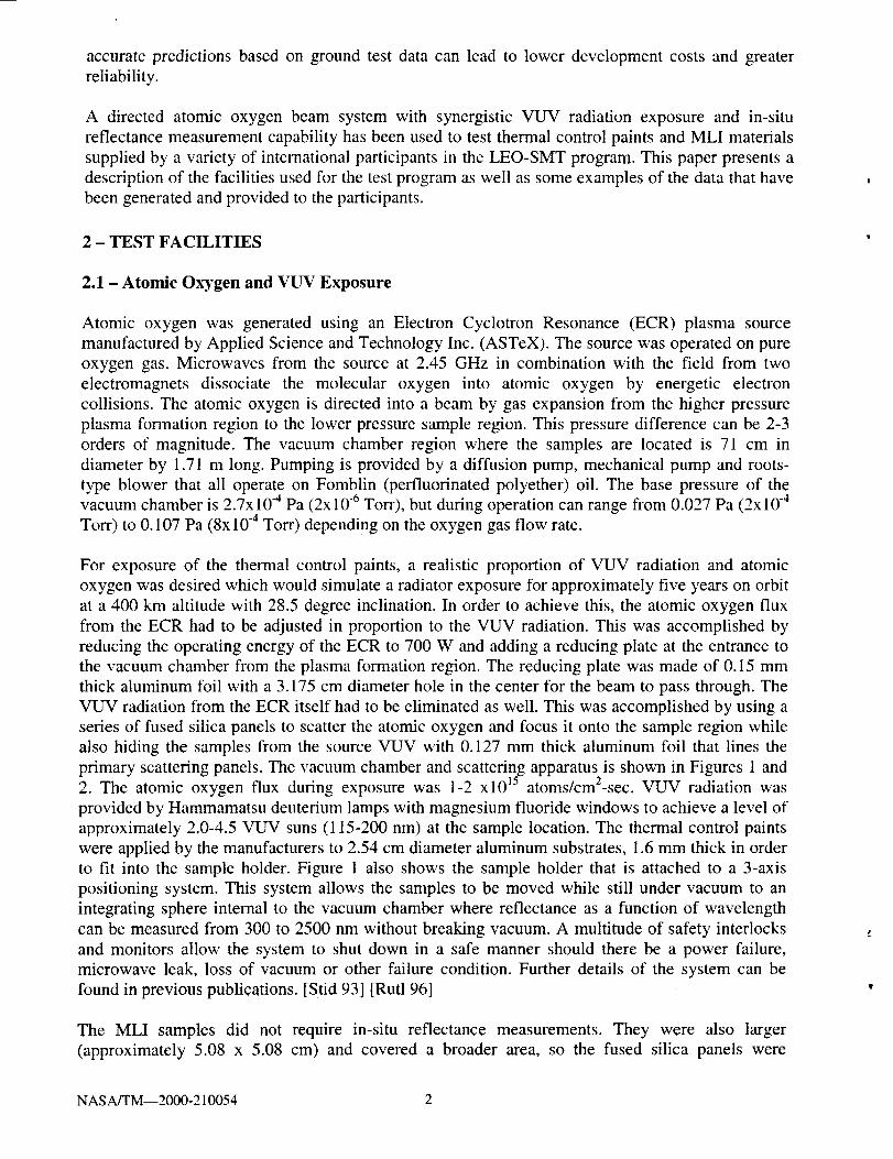
Atomic oxygen was generated using an Electron Cyclotron Resonance (ECR) plasma source
manufactured by Applied Science and Technology Inc. (ASTeX). The source was operated on pure
oxygen gas. Microwaves from the source at 2.45 GHz in combination with the field from two
electromagnets dissociate the molecular oxygen into atomic oxygen by energetic electron
collisions. The atomic oxygen is directed into a beam by gas expansion from the higher pressure
plasma formation region to the lower pressure sample region. This pressure difference can be 2-3
orders of magnitude. The vacuum chamber region where the samples are located is 71 cm in
diameter by 1.71 m long. Pumping is provided by a diffusion pump, mechanical pump and roots-
type blower that all operate on Fomblin (perfluorinated polyether) oil. The base pressure of thevacuum chamber is 2.7x 10 -4 Pa (2x10 -6 Torr), but during operation can range from 0.027 Pa (2x 10 -4
Torr) to 0.107 Pa (8x10 "4 Torr) depending on the oxygen gas flow rate.
For exposure of the thermal control paints, a realistic proportion of VUV radiation and atomic
oxygen was desired which would simulate a radiator exposure for approximately five years on orbit
at a 400 krn altitude with 28.5 degree inclination. In order to achieve this, the atomic oxygen flux
from the ECR had to be adjusted in proportion to the VUV radiation. This was accomplished by
reducing the operating energy of the ECR to 700 W and adding a reducing plate at the entrance to
the vacuum chamber from the plasma formation region. The reducing plate was made of 0.15 mm
thick aluminum foil with a 3.175 cm diameter hole in the center for the beam to pass through. The
VUV radiation from the ECR itself had to be eliminated as well. This was accomplished by using a
series of fused silica panels to scatter the atomic oxygen and focus it onto the sample region while
also hiding the samples from the source VUV with 0.127 mm thick aluminum foil that lines the
primary scattering panels. The vacuum chamber and scattering apparatus is shown in Figures 1 and15 2
2. The atomic oxygen flux during exposure was 1-2 xl0 atoms/cm-sec. VUV radiation was
provided by Hammamatsu deuterium lamps with magnesium fluoride windows to achieve a level of
approximately 2.0-4.5 VUV suns (115-200 nm) at the sample location. The thermal control paints
were applied by the manufacturers to 2.54 cm diameter aluminum substrates, 1.6 mm thick in order
to fit into the sample holder. Figure 1 also shows the sample holder that is attached to a 3-axis
positioning system. This system allows the samples to be moved while still under vacuum to an
integrating sphere internal to the vacuum chamber where reflectance as a function of wavelength
can be measured from 300 to 2500 nm without breaking vacuum. A multitude of safety interlocks
and monitors allow the system to shut down in a safe manner should there be a power failure,
microwave leak, loss of vacuum or other failure condition. Further details of the system can be
found in previous publications. [Stid 93] [Rutl 96]
The MLI samples did not require in-situ reflectance measurements. They were also larger
(approximately 5.08 x 5.08 cm) and covered a broader area, so the fused silica panels were
NASA/TM--2000-210054 2

removed, the sample holder on the multiaxis positioner was retracted farther back into the chamber,
and a fiat sample holder plate installed in its place. The atomic oxygen flux during exposure was
S'_MMETRiCPLASMA /--CIRCULATOR/DIRECTIONAL COUPLER/DUMMY LOADCOUPLER _ /
q.__F__-'---- ELECTROMAGNET
ELECTRON- C'fCLOTRON c---- VA CLIUId
RESONANCE SOURCE / CHA, MBER
---"---- ELE:TROMAGNE:[ // _ iNTEGRAT_NG
___ .PLOW ENERGY / // SPHERE '
_OX','OEN BEAM / / ATTACHMENT
m i_iL_:iJ_'lJ _--_DEuTERIUM LAMP'_ /_ -rF__----_--_IZ ..... _!l , _ LIGH_ , ATH
' ) /-G _A_S ENPLOSI;RE,.... _ _, %, _- REFLE_ VrWrR
/11 .,,,, ,Ill , .-ill PUM-tNGSYSTEM", Ill ; ""
_-u_--'_x_X .... F //Z LIuHT SOUR_ R
''1.71 m ' T d "_-_MONOCHROM' 0
_ },-AXIS SAMPLEPOSITIONER
Figure 1. Side view schematic of vacuum chamber showing ECR source, reflectance measurement system,motion arm, and VUV blocking apparatus (From [Stid 93])
DEUTERIUM
LAMPS (VUV)(NOSE OFLAMPS INSIDEVACUUM
CHAMBER)
TO ECR /_.i QUARTZ
t ,./ LINE%AcUUM
......! , , i............._...........
___ 0
ALUMINUM
FOIL LINERINSIDE FUSED
SAMPLES SILICATRIANGLEPANELS
Figure 2. Atomic oxygen scattering and VUV blocking apparatus inside vacuum chamber
FUSED
SILICAPANELS
WITHSTAINLESS
STRAPS
NASA/TM--2000-210054 3

approximately 4.3x10¹⁵ atoms/cm2-sec with the ECR source operating at 700 W of microwave
power. Because the VUV from the source was not blocked during exposure, VUV at an intensity
of approximately 150 suns (predominantly at 130 nm) was provided to the samples. This was
measured using an Acton Research photomultiplier and filter wheel calibrated to a deuterium lamp
that was calibrated by the National Institute of Standards and Technology (NIST).
The size of the vacuum chamber also allows exposure of spacecraft components to atomic oxygen.
The facility has been used to expose battens under tension [Stid 95], and a section of a solar array
panel under load and rotating to simulate sweeping ram exposure [Fork 96]. The configuration of
the facility allows a great flexibility in the materials tested and the manner in which they are
exposed.
2.2 - Sample Characterization
The reflectance for the thermal control paint samples was measured in-situ using a reflectance
measurement system (RMS) manufactured by Optronic Laboratories Inc. It was designed
specifically for this vacuum chamber. It measures the hemispherical spectral refectance of opaque
samples over a wavelength range from 300 to 2500 nm. The reflectance in air was measured using
a Lambda-9 UV-VIS-NIR spectrophotometer manufactured by Perkin Elmer. It measures the
hemispherical spectral reflectance from 250 to 2500 nm. This instn_ment was used to determine the
in-air solar absorptance of both the thermal control paints and the MLI. The solar absorptance was
calculated by integrating the spectral absorptance (l.0-spectral reflectance) with respect to the air
mass zero solar curve [Raus 80]. The change in mass of the exposed MLI samples was measured
using a Sartorious Balance R-150-P. Thermal emittance was also measured for the MLI samples
using a Gier Dunkle DB-100 Reflectometer. This instrument measures the reflectance at 355 K,
which can be subtracted from unity to obtain the emittance at 355 K.
2.3 - Sample Preparation and Atomic Oxygen Effective Fluence Measurement
Aluminum substrates, 2.54 cm diameter by 1.6 mm thick, were supplied to participating thermal
control paint manufacturers for paint application. MLI material was supplied by the participants as
sheets from which 5.08 cm x 5.08 cm samples were cut for testing. The MLI was fully dehydrated
in vacuum for the pre and post exposure mass measurements in order to minimize errors in mass
measurement due to water absorption. [Rutl 86][Rutl 96] A vacuum dessicator operating at
pressures between 8-13 Pa (60-100 mTorr) was used to dehydrate the samples for a period of 48 hrs
prior to mass measurement. Samples were quickly removed from vacuum and weighed to reduce
errors in mass measurement due to water reabsorption.
The effective fluence of atomic oxygen onto the samples was determined using a 2.54 cm diameter
sample either punched from a 0.0127 cm thick sheet of DuPont Kapton H or a 0.0051 cm thick
sheet of DuPont Teflon FEP. The witness coupon was selected based on the type of material being
exposed. Kapton was used for the thermal control paints and polyimide-based MLI, and Teflon
FEP was included in tests where there was FEP-based MLI. During exposure, the witness coupon
was placed next to the samples being exposed. Knowing the density of the material, the measured
mass toss per unit area during the exposure, and the erosion yield of the material in space, an
effective fluence can be calculated. [Rutl 96] The effective fluence is not an absolute measure of
atoms per unit area arriving at the surface. It is the calculation of the equivalent atoms per unit area
in LEO that would produce the same damage as observed in the ground based facility and is strictly
used as a means of comparison.
NASA/TM--2000-210054 4

3 - TESTING OF THERMAL CONTROL PAINTS
As part of the test program, the reflectance of the thermal control paints exposed to atomic oxygen
and VUV radiation was measured prior to exposure in air, prior to exposure in vacuum, during
exposure at selected intervals in vacuum, and again at the end both in vacuum and in air. Spectral
reflectance data was then plotted as a function of wavelength and sent to the participant that
donated the samples. Figure 3 contains a typical spectral plot as a function of wavelength. This
particular sample experienced a darkening upon atomic oxygen and VUV radiation exposure. The
reflectance of this paint was found to remain fairly stable after an approximately 7.5x10²°
atoms/cm 2 atomic oxygen effective fluence and 816 ESH VUV exposure. Data was not available in
this particular exposure beyond these levels due to difficulties with the RMS system. The
reflectance recovered slightly when the sample was exposed to air. Although not all paint samples
experience a bleaching effect with air, it is important to make measurements in vacuum prior to
venting the exposure chamber. This can provide verification of whether or not bleaching will occur,
thereby giving a better indication of what the change in optical properties can be in space.
.,..a
O
[.-
1.0
0.9
0.8
0.7
0.6
0.5
0.4
0.3
0.2
0.1
0.0 i i i i i i i i i i i
400 600 800 1000 1200 1400 1600 1800 2000 2200 2400
Wavelength (nm)
-- Lambda-9 Pre-Test
........ RMS Pre-Test in Air
RMS Pre-Test In-Vacuum
Lambda-9 Post-Test After Exposure to AO Fluence of 2.59e21 atoms/cm z , 2792 ESH
.... RMS After Exposure to AO Fluence of 7.59e20 atoms/cm 2 , 816 ESH
Figure 3. Hemispherical total spectral reflectance data for PSB Silicate both in air
(before and after exposure with Lambda-9) and in vacuum (before and during with
RMS)
NASA/TM--2000-210054 5

Measured reflectance data was then used to calculate the absorptance spectral data that was
integrated with respect to the air mass zero solar spectra to obtain the solar absorptance of each
sample. These values were tabulated and also supplied to the participant along with an estimate of
the VUV radiation and effective atomic oxygen dose experienced by each sample. These were
estimated by calibration using a positional photodiode, and witness coupons respectively. The
variation of the VUV dose is due to the sample position with respect to the pair of deuterium lamps.
There is some overlap of the lamp output for the two samples in the central sample slots and more
of a single lamp exposure for those on the edge.
Table I contains examples of the integrated solar absorptance data gathered for selected white
thermal control paints. The paints listed that are from MAP are older formulations and do not
represent their current paint products. These and other formulations were tested because they have
been used on spacecraft in the past and can give the participant a basis for comparison and
understanding of their spacecraft's performance.
Table I. White thermal control paint optical and exposure level data
Material and
Manufacturer
Z-93-P (ITTRI)PSB (MAP)SI3GPLO-I
0TTRI)SG120FD (MAP).
Atomic OxygenEffective Fluence
(atoms/cm 2)
4.1x10²_4.1x1021
4.1xt02j
4.lx1021
VUV EquivalentSun Hours (115-
200 nm)1t30
Solar Absorptance(In-vacuum before
exposure)0.09
Solar Absorptance(In-vacuum after
exposure)0.11
1640 0.08 0.18
2200 0.18
0.141590
0.18
0.13
4 - TESTING OF MULTILAYER INSULATION
Solar absorptance data prior to and after atomic oxygen and VUV radiation exposure was ob_taioed
for multilayer insulation samples. An example of the data generated is shown in Table II. Thermal
emittance was also measured prior to and after exposure and is included in the table. The variation
in fluence dose noted in the table is due to the placement of the sample with respect to the atomic
oxygen beam. With the scattering apparatus removed, the beam arriving at the samples follows a
Gaussian distribution pattern.
In general, for the MLI material types tested to date, the solar absorptance increased when the metal
reflector surface was oxidized. Where a stable metal reflector surface existed, the absorptance
remained fairly stable even with a thinning of the first surface material. The samples were not
completely shielded so some atomic oxygen was able to reach the back of the sample. This allowed
some oxidation of the second surface reflector to take place. The emittance, however, seems to be
much more dependent on the first surface. Thinning of the primary surface due to oxidation
resulted in a decrease in thermaI emittance. Materials that exhibited the least change had a coating
on the exposed surface. However, if the coating is disturbed by processing, such as occurred with
the UTC-025R-AAEN embossed aluminum coated polyimide, then atomic oxygen can enter
defects in the coating at the site of the processing and attack the underlying material. In this case,
there were embossed dimples that actually fell out after the MLI was exposed.
Figure 4 shows the mass loss experienced by selected MLI materials with atomic oxygen exposure.
As would be expected, MLI with a first surface of either polyimide or Teflon FEP loses mass with
increased atomic oxygen exposure. The polyimide loss rate is higher than that for FEP as a function
of the effective fluence. Samples with a surface coating exhibited a much lower mass loss as a
NASA/TM 2000-210054 6
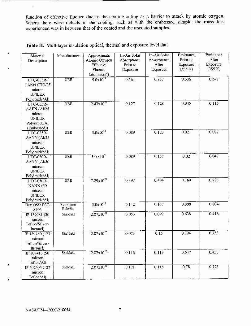
function of effective fluence due to the coating acting as a barrier to attackby atomic oxygen.Where there were defects in the coating, such as with the embossedsample,the mass lossexperiencedwasin betweenthatof thecoatedandtheuncoatedsamples.
Table II. Multilayer insulation optical, thermal and exposure level data
Material
Description
UTC-025R-
TANN (ITO/25micron
UPILEX
Polyimide/A1)UTC-025R-
AAEN (A!/25micron
UPILEX
Polyimide/A1(Embossed))UTC-025R-
AANN (A1/25micron
UPILEX
Polyimide/Al)UTC-050R-
AANN (AI/50micron
UPILEX
Polyimide/Al)UTC-050R-
NANN (50micron
UPILEX
Polyimide/A1)Flex OSR FST-
8403
IP 139481 (50micron
TeflorgSilver-
Inconel)
IP 139480 (127micron
Teflon/Silver-
Inconel)
IP 2O7413 (50micron
Teflon/A1)
IP 502303 (127micron
Teflon/Al)
Manufacturer
UBE
UBE
UBE
UBE
UBE
SumitomoBakelite
Sheldahl
Sheldahl
Sheldahl
Sheldahl
ApproximateAtomic Oxygen
Effective
Fluence
(atoms/cm 2)
5.0x10²¹
2.47x10 _-l
5.0x 10²J
5.0 xl0 -'j
7.29x10²°
5.0x10²¹
2.07xl 0"-"
2.07x10²²
2.07x10-'-"
2.07x10²²
In-Air Solar
AbsorptancePrior to
Exposure
0.364
0.127
0.089
0.089
0.397
0.142
0.053
0.073
0.116
0.121
In-Air Solar
AbsorptanceAfter
Exposure
0.357
0.128
0.123
0.157
0.494
0.137
0.092
0.15
0.113
0.118
EmittancePrior to
Exposure(355 K)
0.536
0.045
0.021
0.02
0.769
0.808
0.638
0.794
0.647
0.78
EmittanceAfter
Exposure(355 K)
0.547
0.115
0.027
0.047
0.723
0.804
0.416
0.753
0.453
0.725
NASA/TM--2000-210054 7

0.010
0.008
0.006
_D
o.oo_
0.002
0.000
..-'"
....++ _
F -/
</-
i * i +
0.0 5.0e+21 1.0e+22 1.5e+22 2.0e+22
Atomic Oxygen Effective Fluence (atoms/cm 2)
2.5e+22
4
---O'"
--.__
...At..,
UBE UTC-050R-NANN (UPILEX Polyimide/Al)
UBE UTC-025R-NANN (UPILEX Polyimide/Al)
Sheldahl IP139480 (127 micron Teflon/Ag-Inconel)
Sheldahl IP 207413 (50 micron Teflon/Aluminum)
Sheldahl IP 502303 (127 micron Teflon/Aluminum)
Sheldahl IP 139481 (50 micron Teflon/Ag-Inconel)
UBE UTC-025R-AAEN (AI on Both Sides of
UP1LEX
UBE UTC-050R-AANN (A1 on Both Sides of
UPILEX Polyimide)
UBE UTC-025R-AANN (AI on Both Sides of
UPILEX Polyimide)
----O.- UBE UTC-025R-TANN (ITO/UPILEX Polyimide/A1)
Figure 4. Mass loss per unit area for selected MLI materials as a function of atomic oxygen effective fluence
5 - LEO-SMT REPORT
Participants in the LEO Spacecraft Materials Test Program have received a brief description of the
tests conducted as well as tables and plots of their data as presented in this paper. Each participant
only receives the information on the materials they have donated and that of a well known baseline
material such as Z-93-P. The results of the tests are only shared with others with the agreement of
the participant donating material.
6 - CONCLUSIONS
The LEO-SMT program was initiated in order to give manufacturers and users information about
the durability and perfor_m_ance of spacecraft materials and components that can be used to
understand spacecraft performance and aid in selection of materials for future missions. Initial
testing has focused on thermal control paints and multilayer insulation (MLI). The initial testingdemonstrated that in-situ measurement of reflectance for white paints is important because it points
nF
NASA[rM--2000-210054 8

out the extent to which some paints darkened by exposure recover some of their original reflectance
when exposed to air. It was also shown that second surface reflector integrity is important for
maintaining the solar absorptance of MLI, while the integrity of the front polymer is important for
maintaining the thermal emittance. Through this testing, general characteristics of classes of
materials can be obtained as well as specific material performance information. Data is provided to
each participant, for their own use, on the materials that they donate. Information from these tests
along with available space data can also be used to develop and validate performance and durability
prediction models. NASA welcomes the opportunity to consider additional international
participants in this program that should greatly aid spacecraft designers of the future in materialselection for LEO missions.
REFERENCES:
[Fork 96] M.J. Forkapa, C.R. Stidham, B.A. Banks, S.K. Rutledge, D.H. Ma, and E.A. Sechkar:
"Atomic Oxygen Durability Testing of an International Space Station Solar Array
Validation Coupon" Protection of Materials and Structures from the Low Earth Orbit
Space Environment, Toronto, Canada, April 1996, NASA TM- 107212.
[Raus 80] H.S. Rauschenbach: Solar Cell Array Design Handbook, Van Nostrand Reinhold Co.,
1980, p411.
[Rutl 86] S. Rutledge, B. Banks, F. DiFilippo, J. Brady, T. Dever and D. Hotes, "An Evaluation of
Candidate Oxidation Resistant Materials for Space Applications in LEO", Workshop on
Atomic Oxygen Effects, Pasadena, Califor_ffa, November 1986, NASA TM- 100122.
[Rutl 96] S.K. Rutledge and B.A. Banks: "A Technique for Synergistic Atomic Oxygen and
Vacuum Ultraviolet Radiation Durability Evaluation of Materials for Use in LEO", 3 rd
International Conference on Protection of Materials and Structures From the Low
Earth Orbit Space Envi_vnment, Toronto, Canada, April 1996, NASA TM-107230.
[Stid 93] C.R. Stidham, T.J. Stueber, B.A. Banks, J.A. Dever, S.K. Rutledge and E.J. Bruckner:
"Low Earth Orbital Atomic Oxygen Environmental Simulation Facility for Space
Materials Evaluation", 38 th blternational SAMPE Symposium and Exhibition, Anaheim,
California, May 1993, NASA TM-106128.
[Stid 95] C.R. Stidham, S.K. Rutledge, E.A. Sechkar, D.S. Flaherty, D.M. Roig and J.L. Edwards:
"Atomic Oxygen Durability Evaluation of the Flexible Batten for the Photovoltaic Array
Mast on Space Station", 1995 International Solar Energy Conference, Lahaina, Maui,
Hawaii, March 1995, NASA TM-106798.
NASA/TM--2000-210054 9
REPORT DOCUMENTATION PAGE Fo,','nApprove_OMB No. 0704-0188
T r7
Public reporting burden for this collection of information is estimated to average 1 hour per response, including the time for reviewing instructions, searching existing data sources,gathering and maintaining the data needed, and completing and reviewing the collection of information. Send comments regarding this burden estimate or any other aspect of thiscollection of information, including suggestions for reducing this burden, to Washington Headquarters Services, Directorate for Information Operations and Reports, 1215 JeffersonDavis Highway, Sure f204, Adlngton, VA 22202-4302, and to the Office of Management and Budget, Paperwork Reduction Project (0704-0188), Washington, DC 20503.
1. AGENCY USE ONLY (Leave blank) 2. REPORT DATE 3. REPORT TYPE AND DATES COVERED
May 2000 Technical Memorandum
4. TITLE AND SUBTITLE 5. FUNDING NUMBERS
International Test Progranl for Synergistic Atomic Oxygen and VUV
Exposure of Spacecraft Materials
6. AUTHOR(S)
Sharon Rutledge, Bruce Banks, Joyce Dever, and William Savage
! 7. PERFORMING ORGANIZATION NAME(S) AND ADDRESS(ES)
National Aeronautics and Space Administration
John H. Glenn Research Center at Lewis Field
Cleveland, Ohio 44135- 3191
9. SPONSORING/MONITORING AGENCY NAME(S) AND ADDRESS(ES)
National Aeronautics and Space Administration
Washington, DC 20546-0001
11. SUPPLEMENTARY'NoTES
WU-632-6A-1E--00
8. PERFORMING ORGANIZATION
REPORT NUMBER
E-12255
10. SPONSORING/MONITORING
AGENCY REPORT NUMBER
NASA TM--2000-210054
Prepared for the 8th International Symposium on Materials in a Space Environment and the 5th International Conference
on Protection of Materials and Structures from the LEO Space Environment cosponsored by the CNES, Integrity Testing
Laboratory, ESA, ONERA, and the Canadian Space Agency, Arcachon, France, June 5-9, 2000. Sharon Rutledge, Bruce
Banks, and Joyce Dever, NASA Glenn Research Center; William Savage, Cleveland State University, 1983 E. 24th St.,
Cleveland, Ohio 44115-2403. Responsible person, Sharon Rutledge, organization code 5480, (216) 433-22t9.
12a. DISTRIBUTION/AVAiLABILITY STATEMENT
Unclassified - Unlimited
Subject Category: 27 Distribution: Nonstandard
This publication is available from the NASA Center for AeroSpace Information, (301) 621-0390.
12b. DISTRIBUTION CODE
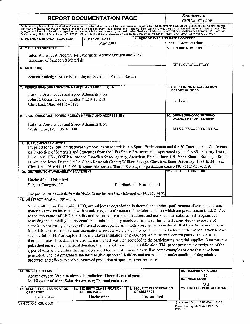
13. ABSTRACT (Maximum 200 words)
Spacecraft in low Earth orbit (LEO) are subject to degradation in thermal and optical performance of components and
materials through interaction with atomic oxygen and vacuum ultraviolet radiation which are predominant in LEO. Due
to the importance of LEO durability and performance to manufacturers and users, an international test program for
assessing the durability of spacecraft materials and components was initiated. Initial tests consisted of exposure of
samples representing a variety of thermal control paints and multilayer insulation materials that have been used in space.
Materials donated from various international sources were tested alongside a material whose performance is well known
such as Teflon FEP or Kapton H for multilayer insulation, or Z-93-P for white thermal control paints. The optical,
thermal or mass loss data generated during the test was then provided to the participating material supplier. Data was not
published unless the participant donating the material consented to publication. This paper presents a description of the
types of tests and facilities that have been used for the test program as well as some examples of data that have been
generated. The test program is intended to give spacecraft builders and users a better understanding of degradation
processes and effects to enable improved prediction of spacecraft performance.
14. SUBJECT TERMS
Atomic oxygen; Vacuum ultraviolet radiation; Thermal control paint;
Muhilayer insulation; Solar absorptance; Thermal emittance
17. SECU RITY C LASSIFICATION
OF REPORT
Unclassified
NSN 7540-01-280-5500
18. SECURITY CLASSIFICATIONOF THIS PAGE
Unclassified
19. SECURITY CLASSIFICATIONOF ABSTRACT
Unclassified
15. NUMBER OF PAGES
1516. PRICE CODE
AQ_20. LIMITATION OF ABSTRACT
Standard Form 298 (Rev. 2-89)
Prescribed by ANSI Std. Z39-1B298-102
Recommended