Interaction between Boundary Layer and Shock in
Hypersonic Flows with chemical real gas effects
Nabi Jahantigh1, M.Mirzaei
2, A. Shadaram
3
Mechanical engineering department
Zabol University
Jahad square - Zabol
Iran
Email: [email protected]
ABSTRACT
In this paper, viscous interaction phenomenon in hypersonic flows with chemical
reactions is numerically simulated. Two-dimensional Navier-Stokes equations are
solved to simulate this phenomenon. Inviscid fluxes are approximated using Van
Leer flux vector splitting method and to increase the accuracy of this
approximation, MUSCL approach with Van albada limiters is applied. Chemical
reactions are considered to be in equilibrium conditions. With this assumption there
is no closed form for equation of state for the gas (air) and relation between
thermodynamic properties are calculated from thermodynamic tables. In addition,
transport properties (viscosity and conductivity) are functions of two independent
thermodynamic properties. These functions are calculated using kinetic theory. To
evaluate the performance of the model used in this research, some test cases are
studied. First test case is flow over a ramp with various angles. The results of this
test case are compared with the results of other numerical methods and the effect of
geometry on separation length is studied. The second case is a hypersonic flow over
a 15-degree ramp. The results are in good agreement compared with experimental
data. In addition, there results are compared with the results of ideal gas (non-
reacting flow) calculations. It can be seen that ideal gas assumption for air
introduces considerable deviation form experimental data.
Keywords: Compressible navier stokes equations- Interaction-Flux vector descretise-
Shock waves- Limiter-Chemical reaction
1 Head of department of mechanics
2 Assistant Professor
3 Assistant Professor
Proceedings of the 4th WSEAS International Conference on Fluid Mechanics and Aerodynamics, Elounda, Greece, August 21-23, 2006 (pp68-74)
1 Introduction
Viscous interaction is one of the major aspects of
hypersonic flows. Interaction between a shock
wave and a boundary layer can produce a region of
separated flow. The phenomenon may occur, for
example, at the upstream-facing corner formed by
deflected control surface on a hypersonic reentry
vehicle, where the length of separation has
implications for control effectiveness. Separation
can also occur where a shock wave generated
internally to a hypersonic air-breathing propulsion
system impinges on a boundary layer. Thus
separation length may be important in determining
engine performance. In addition, knowledge
regarding separation length in shock/boundary-
layer interactions has relevance to separation
length in supersonic wake flow. Various
experimental and numerical works have been
carried out to simulate this problem. Since this
problem involves downstream effects, especially in
separation regions, models based on boundary
layer theory or parboiled Navier-stokes (PNS) lead
to inaccurate results. So, usually full Navier-Stokes
equations are employed to analyze this problem [1-
5]. This phenomenon is normally simultaneous
with fluid chemical reaction due to high
temperature effects Because of this; several
researchers have considered the effects of chemical
reactions [6-11]. These effects are normally called
“real gas effects”. Chemical reactions, depending
on the flow time scale, may be assumed to be in
equilibrium [6-8] or in non-equilibrium [9-11]
conditions. In this Paper, this problem is modeled
using full Navier-Stokes equations and the effects
of chemical reaction with equilibrium assumption
on the results are evaluated. Separation length,
pressure distribution, friction factor, and heat
transfer coefficient are parameters, which are
studied in this research.
2 Governing Equations
Navier-stokes equations are used to simulate this
phenomenon. These equations in conservative
form in a generalized coordinate system ),( ηξ are
express as follow:
y
F
x
E
y
F
x
E
t
Q vvii
∂∂
+∂∂
=∂∂
+∂∂
+∂∂
(1)
Where, Q is vector of dependent variables, iE and
iF are in viscid fluxes, and vE and
vF are
Viscous flux. To close the system of equations,
relations between thermodynamic variables are
required, along with expressions for the transport
properties µ and k . For flow with no chemical
reaction, prefect gas equation of state can be used.
For transport properties, viscosity is calculated using
Sutherland equation and Prandle number is assumed
to be constant. For a chemical reacting flow, these
correlations are not very simple. In this paper,
chemical reactions are considered to be in
equilibrium conditions and the working fluid is air.
For equilibrium air computations, approximate
curve fits are employed to correlate thermodynamic
properties and calculation of transport properties.
The thermodynamic properties are obtained using
the correlations:
)~,e~(~~),~,e~(~~),~,e~(p~p~ ρµ=µργ=γρ=
)~,e~(T~
T~
),~,p~(T~
T~
),~,p~(h~
h~
ρ=ρ=ρ= (2)
Developed by Srinivasan et al.[12], This curve fits
Are valid for temperatures up to 15000o K and
Density ratio from 10- 7 to 103 . The pressure is
Computed using the expression:
e~~)1~(p~ ρ−γ= (3)
Hereγ~ is defined by:
e~/h~~ =γ (4)
For perfect-gas computation, ∞= γγ~ .The curved
Fits for the transport properties were also developed
by Srinivasan et al. [13], and include the following
correlations:
Proceedings of the 4th WSEAS International Conference on Fluid Mechanics and Aerodynamics, Elounda, Greece, August 21-23, 2006 (pp68-74)
)~,e~(k~
k~
),~,e~(~~ ρ=ρµ=µ (5)
The curves fits are constructed based on kinetic
theory and are valid for temperature up to 15000o
K and density ratio from 10-5 to 10.
3 Numerical Method
Finite volume technique is used to descritize the
governing equations in a structural grid and for
temporal approximation, simple explicit method is
applied. The descritized form of the governing
equations in a computational cell is:
iv
4
1i
i ]An).FF[(V
tQ ∆−
∆∆
−=∆ ∑=
(6)
The next step is approximation of viscous and in
viscid fluxes. Viscous fluxes are approximated by
central differencing. This approximation is
compatible with physical nature of these fluxes.
There are various kinds of method to approximate
in viscid fluxes on cell boundaries. In this paper
Van Leer flux vector splitting is used for this
approximation. In this approach, flux vectors are
splitted to positive and negative based on local
Mach number. Negative fluxes are calculated from
left side of a cell boundary and positive fluxes are
calculated from right side of the boundary. This
method in comparison with other methods such as
Stegar-Warming method [14], has better ability in
shock capturing. General forms of splitted fluxes
are as follow [15]:
−γ
±−γ+
−
γ
±−+
γ
±−+
×= ±±
)1(2
]c2v)1[(
2
vV
)c2v(nv
)c2v(nu
1
FF
2
2nn
22
ny
ny
)n(mass
)n(
(7)
4
)1(cF
2n)n(
mass
±Μρ±=± (8)
Where u and v are velocity components in
Cartesian coordinate system, c is local sonic
velocity, Mn is local Mach number based on normal
velocity, nx ,ny are components of unit vector
normal to cell boundary vn is velocity component in
normal direction. The lateral flux for function Φ
has the following form:
( ) TT,massBB,mass FFv φ+φ=ρ −+ (9)
Or
( ) ( )
( )
φ−φ−−
φ+φ+=ρ
−+
−+
2FF
2FFv
BTT,massB,mass
TBT,massB,mass
(10)
The first term of equation (9) indicates a central
approximation and the second terms shows
numerical diffusion. If one of the fluxes is plotted
versus Mach number, it can be seen that for zero
Mach number, splitted flux is not zero. So if we
define such a function that results zero splitted flux
at zero Mach number, numerical diffusion will be
zero. Since first order Van Leer scheme presents
numerical diffusion error, MUSCL approximation
[16] is used to remove this drawback, In this
approximation,L
jiQ ,2/1+ , R
jiQ ,2/1+ are defined as
follow:
)]QQ(
)K1()QQ(
)K1([25.0.QQ
j,ij,1i
LLj,1ij,i
LLj,i
Lj,2/1i
−
×Ψ+Ψ+−
×Ψ−Ψ+=
+
−
+
(11)
And
)]QQ(
)K1()QQ(
)K1([25.0.QQ
j,ij,1i
RRj,1ij,2i
RRj,i
Rj,2/1i
−
×Ψ+Ψ+−×
Ψ−Ψ−=
+
++
+
(12)
WhereLΨ and
RΨ are limiters which are used to
suppress numerical oscillations. In this paper Val
Albada limiters [16] is applied. The general forms of
these limiters are as follow:
ε+−+−
ε+−×−=Ψ
+++
+++2
j,ij,1i2
j,1ij,2i
j,ij,1ij,1ij,2iR
)QQ()QQ(
)]QQ()QQ[(2
(13-a)
Proceedings of the 4th WSEAS International Conference on Fluid Mechanics and Aerodynamics, Elounda, Greece, August 21-23, 2006 (pp68-74)
ε+−+−
ε+−×−=Ψ
−++
−++
2j,1ij,i
2j,1ij,1i
j,1ij,ij,1ij,1iL
)QQ()QQ(
)]QQ()QQ[(2
(13-b)
Where, 1c is the cell size, V flow velocity, and c
local sonic velocity
4 Results
Two test cases have been carried out and the
results are compared with the results of other
numerical methods and experimental data.
4.1 Case1:
The first problem is flow over a compression
corner with the following free stream condition: 4
L 10681K216T3 ×===Μ ∞∞ .Re,,. o
The ramp is in constant temperature of 660 K in
this problem downstream effects are very strong.
Figures 1 to 4 show the results of this problem.
The results are obtained from the solution of the
problem in grid with 52 non-uniform distributed
points in lateral direction and 101 uniform
distributed in longitudinal direction This grid size
insures us for grid independency of the results.
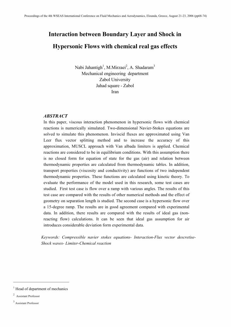
Figure 1 shows pressure coefficient along the ramp
for ramp angle of 10 degree. In this figure, the
results of present calculations are compared with
the results of Navier-Sokes calculation reference
[1]. Good agreement can be seen between these
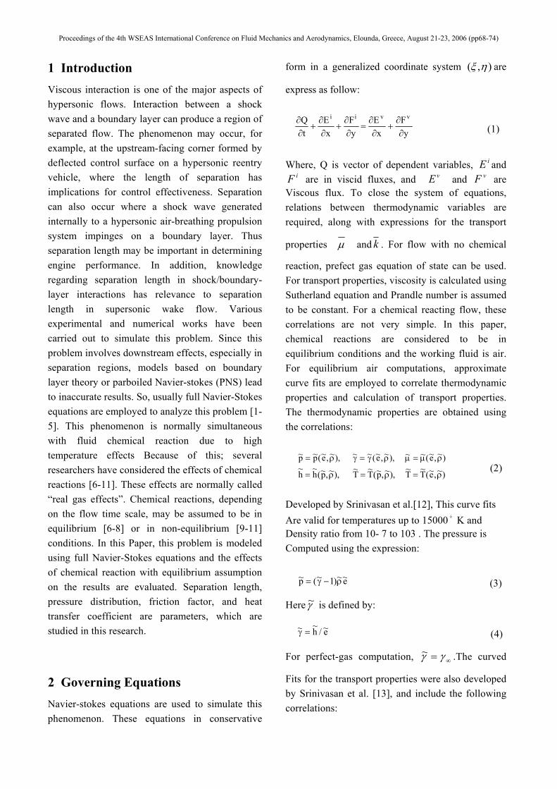
two results. Stanton number distribution along 10
degree ramp is shown in figure 2. In this figure,
the results of this study are compared with other
Navier-Stokes calculation presented in reference
[1] and [2]. We can see that Stanton number
distribution predicted by the present scheme has
excellent agreement with the results of [1] and [2].
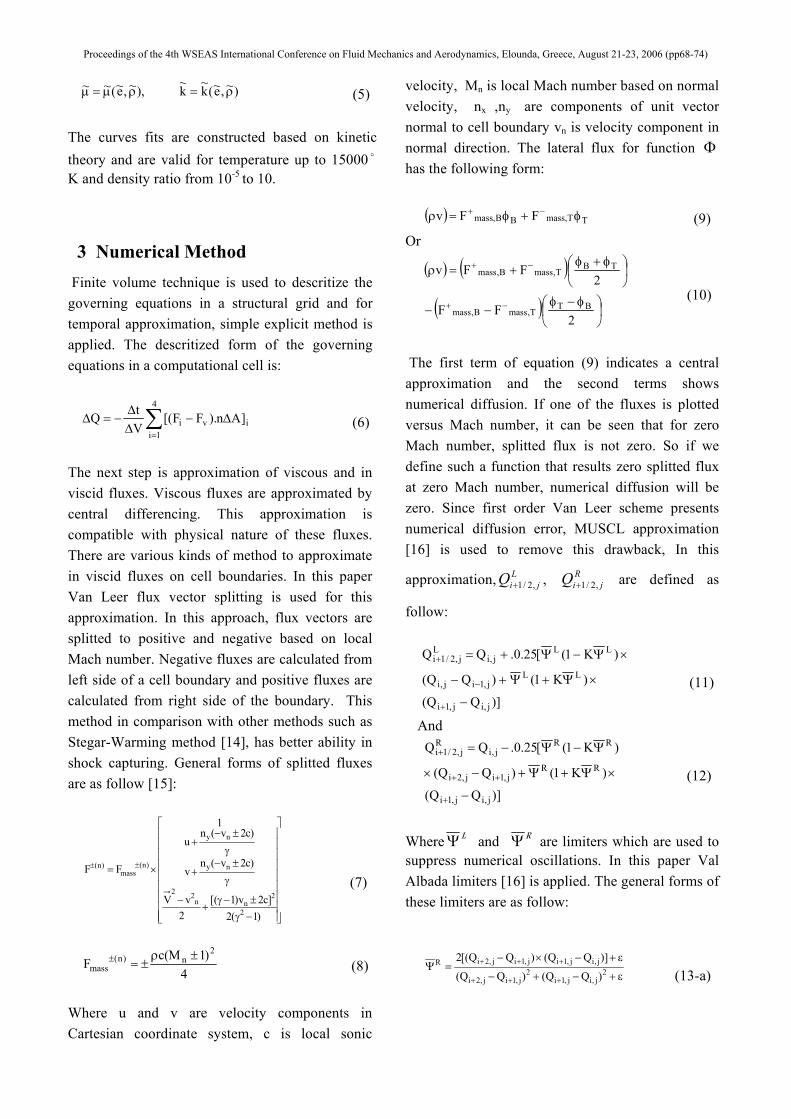
One of the major parameter in viscous interaction
problem is separation length. This parameter is a
function of flow conditions and geometry. For this
case the effect of geometry on the separation
length is shown in figure 3. It can be seen that
increasing the ramp angle causes increasing the
separation length. Figure 4 shows streamlines
around the separation region for a 25-degree ramp.
Fig.1: Pressure coefficient along 10 degree ramp
Figure 2 Stanton Number for case 1
Figure 3: Effect of ramp angle on separation
length
Proceedings of the 4th WSEAS International Conference on Fluid Mechanics and Aerodynamics, Elounda, Greece, August 21-23, 2006 (pp68-74)
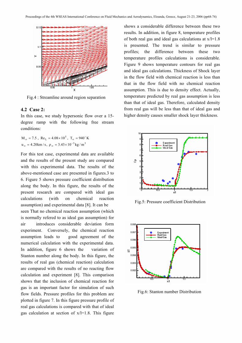
Fig.4 : Streamline around region separation
4.2 Case 2:
In this case, we study hypersonic flow over a 15-
degree ramp with the following free stream
conditions:
33
5L
m/kg1043.3,s/km20.4u
K940T,1008.4Re,5.7
−∞∞
∞∞
×=ρ=
=×==Μ o
For this test case, experimental data are available
and the results of the present study are compared
with this experimental data. The results of the
above-mentioned case are presented in figures.3 to
6. Figure 5 shows pressure coefficient distribution
along the body. In this figure, the results of the
present research are compared with ideal gas
calculations (with on chemical reaction
assumption) and experimental data [8]. It can be
seen That no chemical reaction assumption (which
is normally refered to as ideal gas assumption) for
air introduces considerable deviation form
experiment. Conversely, the chemical reaction
assumption leads to good agreement of the
numerical calculation with the experimental data.
In addition, figure 6 shows the variation of
Stanton number along the body. In this figure, the
results of real gas (chemical reaction) calculation
are compared with the results of no reacting flow
calculation and experiment [8]. This comparison
shows that the inclusion of chemical reaction for
gas is an important factor for simulation of such
flow fields. Pressure profiles for this problem are
plotted in figure 7. In this figure pressure profile of
real gas calculations is compared with that of ideal
gas calculation at section of x/l=1.8. This figure
shows a considerable difference between these two
results. In addition, in figure 8, temperature profiles
of both real gas and ideal gas calculations at x/l=1.8
is presented. The trend is similar to pressure
profiles; the difference between these two
temperature profiles calculations is considerable.
Figure 9 shows temperature contours for real gas
and ideal gas calculations. Thickness of Shock layer
in the flow field with chemical reaction is less than
that in the flow field with no chemical reaction
assumption. This is due to density effect. Actually,
temperature predicted by real gas assumption is less
than that of ideal gas. Therefore, calculated density
from real gas will be less than that of ideal gas and
higher density causes smaller shock layer thickness.
Fig.5: Pressure coefficient Distribution
Fig.6: Stanton number Distribution
Proceedings of the 4th WSEAS International Conference on Fluid Mechanics and Aerodynamics, Elounda, Greece, August 21-23, 2006 (pp68-74)
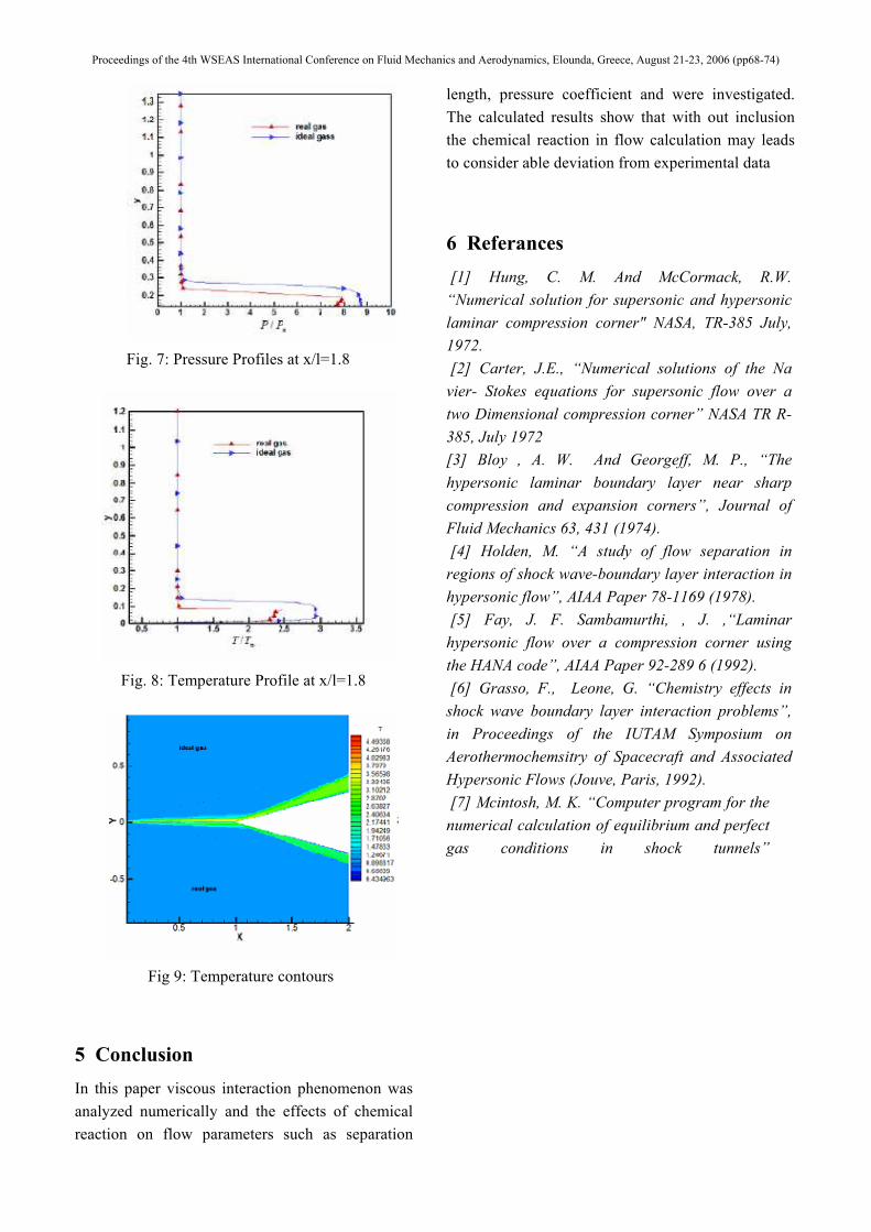
Fig. 7: Pressure Profiles at x/l=1.8
Fig. 8: Temperature Profile at x/l=1.8
Fig 9: Temperature contours
5 Conclusion
In this paper viscous interaction phenomenon was
analyzed numerically and the effects of chemical
reaction on flow parameters such as separation
length, pressure coefficient and were investigated.
The calculated results show that with out inclusion
the chemical reaction in flow calculation may leads
to consider able deviation from experimental data
6 Referances
[1] Hung, C. M. And McCormack, R.W.
“Numerical solution for supersonic and hypersonic
laminar compression corner" NASA, TR-385 July,
1972.
[2] Carter, J.E., “Numerical solutions of the Na
vier- Stokes equations for supersonic flow over a
two Dimensional compression corner” NASA TR R-
385, July 1972
[3] Bloy , A. W. And Georgeff, M. P., “The
hypersonic laminar boundary layer near sharp
compression and expansion corners”, Journal of
Fluid Mechanics 63, 431 (1974).
[4] Holden, M. “A study of flow separation in
regions of shock wave-boundary layer interaction in
hypersonic flow”, AIAA Paper 78-1169 (1978).
[5] Fay, J. F. Sambamurthi, , J. ,“Laminar
hypersonic flow over a compression corner using
the HANA code”, AIAA Paper 92-289 6 (1992).
[6] Grasso, F., Leone, G. “Chemistry effects in
shock wave boundary layer interaction problems”,
in Proceedings of the IUTAM Symposium on
Aerothermochemsitry of Spacecraft and Associated
Hypersonic Flows (Jouve, Paris, 1992).
[7] Mcintosh, M. K. “Computer program for the
numerical calculation of equilibrium and perfect
gas conditions in shock tunnels”
Proceedings of the 4th WSEAS International Conference on Fluid Mechanics and Aerodynamics, Elounda, Greece, August 21-23, 2006 (pp68-74)

Proceedings of the 4th WSEAS International Conference on Fluid Mechanics and Aerodynamics, Elounda, Greece, August 21-23, 2006 (pp68-74)
Recommended