Intense Diagnostic Neutral Beam For Burning PlasmasChallenges for ITER and Opportunities for KSTAR
Jaeyoung Park
Glen Wurden and MFE team
Los Alamos National Laboratory
US-Korea workshop, Sad Diego, May 19, 2004Presented at the US ITER Forum, Univ.. of Maryland, May 8, 2003

Why IDNB?
• Upcoming burning plasma experiments (ITER or FIRE) • Intense diagnostic neutral beam (IDNB): Critical baseline diagnostics for burning plasma experiments.
- CHarge Exchange Recombination Spectroscopy (CHERS): ion temperature profile, impurity and helium ash measurements and fast alpha distribution.- Motional Stark Effect (MSE): current profile (q-profile).
• Current technology on diagnostic neutral beam: unlikely to work on burning plasmas due to beam penetration, increased background noise -> low S/N.
• Intense (~ 100 A/cm2) pulsed beam: better S/N.• LANL has hardware, history and expertise (since 90s) and personnel for pulsed IDNB source R&D.
Existing IDNB Hardware at LANL
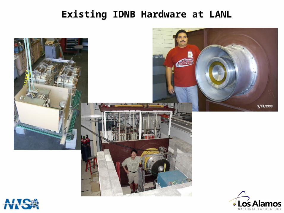
Conventional DNB in burning plasmas? How well will it work?
• Burning plasmas: higher electron density and larger plasma dimension --> beam penetration problem
• Visible background bremsstrahlung: main source of noise and increase with radius and ne
2 (while CHERS signal increase
with ne)
• Increasing beam intensity: very costly in CW beam.• Proposed ITER heating beam: H- based at 500 keV vs. ~125 keV for optimal beam energy for CHERS (need for DNB)
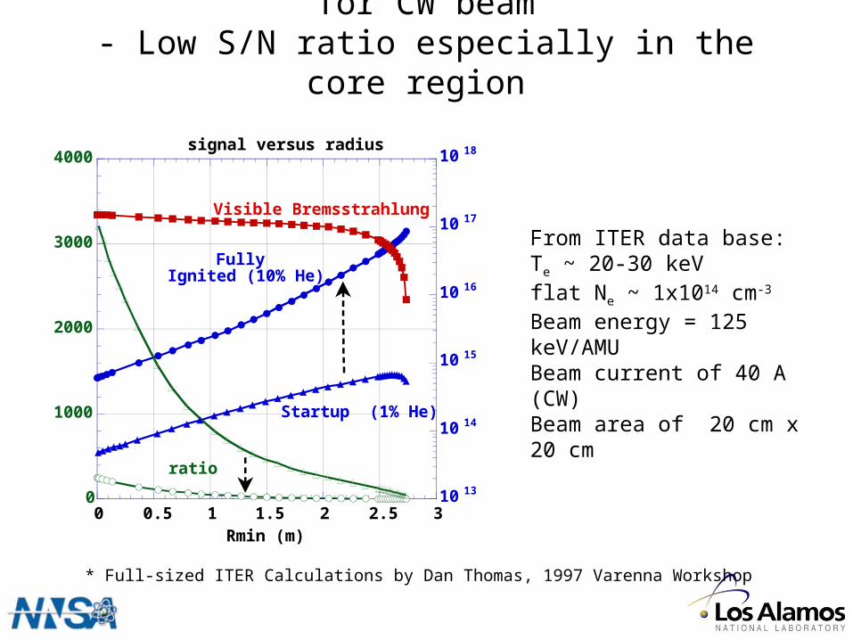
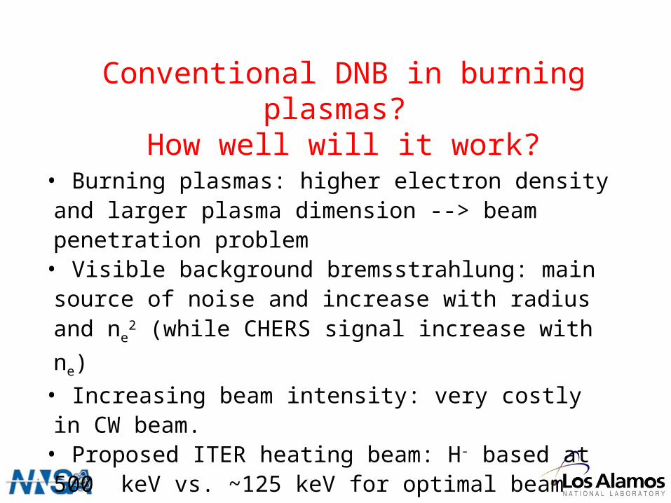
Bremsstrahlung vs. CER signal levels for CW beam- Low S/N ratio especially in the core region
0
1000
2000
3000
4000
10 13
10 14
10 15
10 16
10 17
10 18
0 0.5 1 1.5 2 2.5 3
signal versus radius
ratio: VB/He CER (486 nm)
Ph/cm
2/s/sr/nm
Rmin (m)
Visible Bremsstrahlung
Fully Ignited (10% He)
Startup (1% He)
ratio
* Full-sized ITER Calculations by Dan Thomas, 1997 Varenna Workshop
From ITER data base: Te ~ 20-30 keVflat Ne ~ 1x1014 cm-3 Beam energy = 125 keV/AMUBeam current of 40 A (CW)Beam area of 20 cm x 20 cm
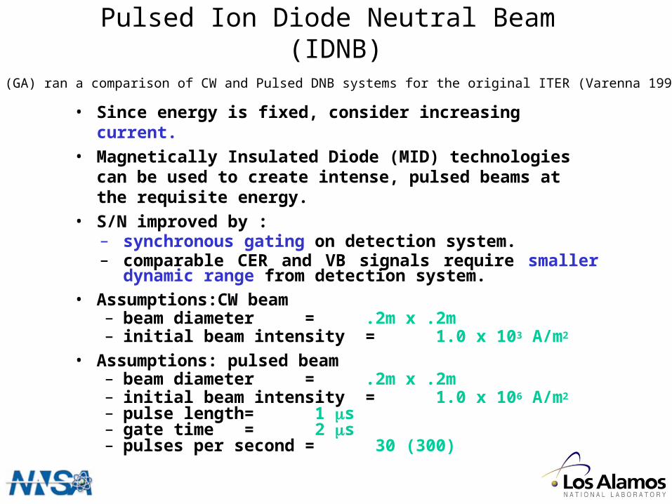
Pulsed Ion Diode Neutral Beam (IDNB)
• Since energy is fixed, consider increasing current.
• Magnetically Insulated Diode (MID) technologies can be used to create intense, pulsed beams at the requisite energy.
• S/N improved by :– synchronous gating on detection system.– comparable CER and VB signals require smaller dynamic
range from detection system.• Assumptions:CW beam
– beam diameter = .2m x .2m– initial beam intensity = 1.0 x 10³ A/m2
• Assumptions: pulsed beam– beam diameter = .2m x .2m– initial beam intensity = 1.0 x 10⁶ A/m2
– pulse length = 1 s– gate time = 2 s– pulses per second = 30 (300)
Dan Thomas (GA) ran a comparison of CW and Pulsed DNB systems for the original ITER (Varenna 1997 Workshop)
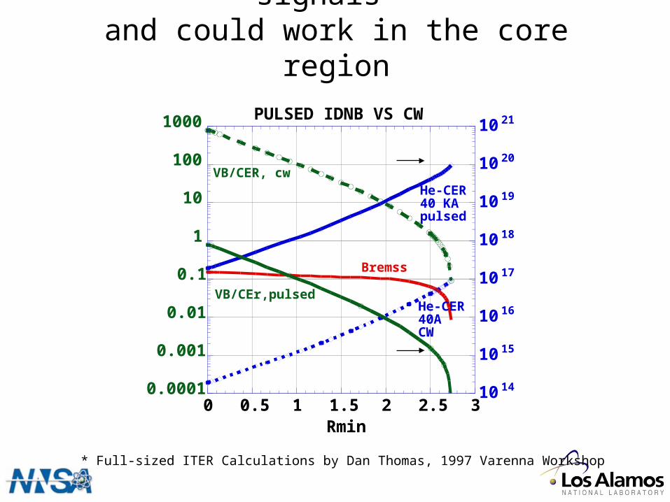
Pulsed IDNB yields much larger signals* and could work in the core region
0.0001
0.001
0.01
0.1
1
10
100
1000
10 14
10 15
10 16
10 17
10 18
10 19
10 20
10 21
0 0.5 1 1.5 2 2.5 3
PULSED IDNB VS CW
Ratio:VB/He-CER
Ph/cm2/s/sr/nm
Rmin
He-CER40ACW
VB/CER, cw
VB/CEr,pulsed
He-CER40 KApulsed
Bremss
* Full-sized ITER Calculations by Dan Thomas, 1997 Varenna Workshop

Technical approach•Intense ion beam source: Magnetically Insulated Diode (MID)
-beam extraction over Child-Langmuir (CL) limit (~ 100 times)• Plasma anode: clean beam with long lifetime• Repetitive pulse operation: short pulses (1-2 s) with high rep-rate (~ 30 Hz)
- improve S/N ratio with low cost.• Optimal beam energy: @ 125 keV/amu for CHERS. Independent from neutral heating beam.
Potential show stoppers• Beam divergence: 1˚ or less divergence required. Not yet proven with MID with plasma anode at high beam extraction.• Lifetime issue: 10,000 shots or more. May not be compatible with high beam extraction (~ 100 times CL limit), high power (~ 4 GW peak power), low beam divergence, etc.• Repetition rate: gas handling and cooling requirement.
LANL IDNB Proposal
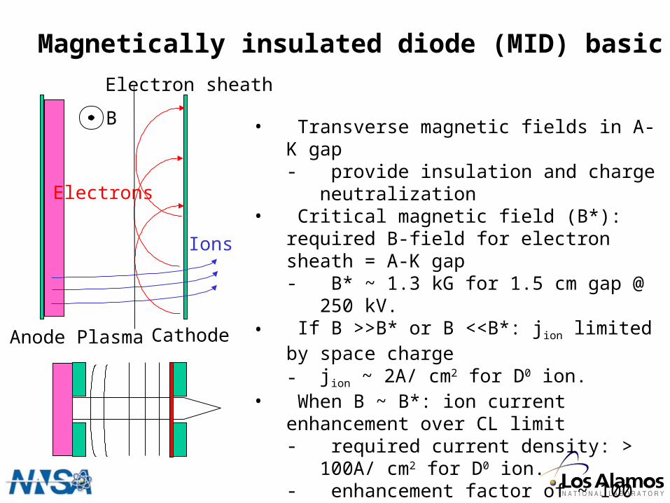
Magnetically insulated diode (MID) basic
• Transverse magnetic fields in A-K gap- provide insulation and charge neutralization
• Critical magnetic field (B*): required B-field for electron sheath = A-K gap- B* ~ 1.3 kG for 1.5 cm gap @ 250 kV.
• If B >>B* or B <<B*: jion limited by space charge- jion ~ 2A/ cm2 for D0 ion.
• When B ~ B*: ion current enhancement over CL limit- required current density: > 100A/ cm2 for D0
ion.- enhancement factor of ~ 100 was obtained
(by Ueda et al. in 1993) for H0 ion beam.• Beam extraction will be done in the cathode
opening
B
Anode Plasma Cathode
Ions
Electrons
Electron sheath
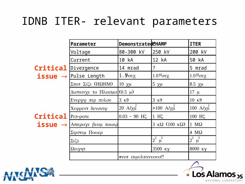
IDNB ITER- relevant parameters
Parameter Demonstrated* CHAMP ITER
Voltage 80-300 kV 250 kV 200 kV
Current 10 kA 12 kA 50 kA
Divergence 14 mrad ? 5 mrad
Pulse Length 1.5 sec 1.0 sec 1.0 sec
( )Spot Size HWHM 10 cm 5 cm 8.5 cm
Distance to Plasma (0.5 )m 17 m
Energy per pulse 3 kJ 3 kJ 10 kJ
Current density 20 /A cm2 >100 /A cm2 100 /A cm2
-Rep rate 0.03 - 90 Hz 1 Hz 100 Hz
Average beam power 3 (100 )kW kW 1 MW
System Power 4 MW
Size 23 m3 23 m3
Weight 3500 kg 8000 kg
* !!not simultaneous
Critical issue
Critical issue
In relation to ITER • Beam divergence, gas handling and repetition rate, lifetime and reliability - all critical issues for IDNB performance• KSTAR is a logical choice for IDNB demonstration and deployment• Successful operation of IDNB ensures the critical diagnostic capability for ITER
Specific to KSTAR• High S/N ratio and excellent spatial resolution• Diagnostic flexibility (independent of NBI) • Low power consumption (100 kW@ 30 Hz) and small footprint
Opportunities for KSTAR

IDNB R&D (2-3 years) - LANL lead• FY 06 funding requested• MID operation and performance optimization
- High beam extraction (~ 100 x CL limit)- Low beam divergence (5-10 mrad)- Lifetime (~ 100,000 shots)- Optimize the repetition rate (10 - 100 Hz)
• Design tool for MID system - 2D fluid + PIC simulation
Deployment and Demonstration (2-3 years) - KSTAR lead• Prototype construction and installation
- Beam neutralization (gas handling and pumping requirement) specific to KSTAR
• DNB capability to KSTAR• IDNB performance demonstration for ITER
Project scope and expected schedule
Proposal Title: Intense Diagnostic Neutral Beam For Burning Plasmas
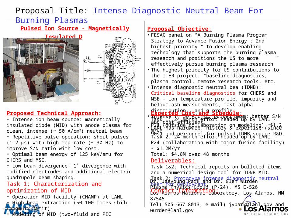
Pulsed Ion Source - Magnetically Insulated Diode Proposal Objective:• FESAC panel on “A Burning Plasma Program Strategy to Advance
Fusion Energy”: 2nd highest priority “ to develop enabling technology that supports the burning plasma research and positions the US to more effectively pursue burning plasma research”
• The highest priority for US contributions to the ITER project: “baseline diagnostics, plasma control, remote research tools, etc.”
• Intense diagnostic neutral bea (IDNB): Critical baseline diagnostics for CHERS and MSE - ion temperature profile, impurity and helium ash measurements, fast alpha distribution., and q profile.
• Intense (~ 50 A/cm2), pulsed beam: better S/N and cost efficient.• LANL has hardware, history & expertise (since 90s) and personnel
for pulsed IDNB source R&D.
Expected Cost and Schedule:Task 1: 24 month effort headed up by LANL - P24 (outside collaboration on modeling) ~$1.2 M/yrTask 2: 24 month effort headed up by LANL - P24 (collaboration with major fusion facility) ~ $1.2M/yrTotal: $4.8M over 48 monthsDeliverables:Task 1&2: Technical reports on bulleted items and a numerical design tool for IDNB MID.Task 2: Prototype intense diagnostic neutral beam for deployment.Contact Information:
Proposed Technical Approach:• Intense ion beam source: magnetically insulated diode (MID) with anode plasma for clean, intense (~ 50 A/cm2) neutral beam• Repetitive pulse operation: short pulses (1-2 s) with high rep-rate (~ 30 Hz) to improve S/N ratio with low cost.• Optimal beam energy of 125 keV/amu for CHERS and MSE.• Low beam divergence: 1˚ divergence with modified electrodes and additional electric quadrupole beam shaping.Task 1: Characterization and optimization of MID• Operation MID facility (CHAMP) at LANL• High beam extraction (50-100 times Child-Langmuir limit)• Modeling of MID (two-fluid and PIC simulation).Task 2: Deployment of prototype diagnostic beam• Parallel beam extraction with electrode modification.• Efficient neutralization and high rep-rate• Deployment ready at major fusion facility in 4 years
Dr. Jaeyoung Park and Dr. Glen WurdenPlasma Physics Group (P-24), MS E-526Los Alamos National Laboratory, Los Alamos, NM 87545Tel) 505-667-8013, e-mail) [email protected] and [email protected]
Recommended