k
Location Item Description Specification
A MODULE 1Plug-in comm module
Communication module options
B ETHERNET Ethernet port built-in on-board Ethernet connection (10Base-T/100Base-T)
C USB USB port USB connector (for firmware updates and RPS connection)
D Heartbeat LED Slow=normal, rapid=service mode
E Reset Reset switch Hold five seconds to enter or exit service mode
F B C Outputs B(2) C(3) Open collector, 50mA, active low
G TMPR Tamper Optional tamper switch connector (ICP-EZTS)
H1 COM 2 to 7 COM 8
Alarm inputs End Of Line (EOL) resistor supervised alarm inputs
I R Y G B SDI2 bus SDI2 device bus
J COM AUX Aux power 12 VDC, 800mA
K NO C NC Output A(1) Programmable relay output
L+ BAT –18 VAC,
Battery, Earth ground, 18 VAC
Primary/Secondary power and Earth Ground connections
M Mounting Mounting holes Mounting holes for control panel
Control panel connection location
B Series Control PanelInstaller Quick Start GuideUse this guide to quickly install a Bosch B6512/B5512/B4512/B3512 security system. Additional information is found in the Control Panels Installation Manual.
For additional training:
Bosch YouTube channel:
When you see this icon, use your smart phone with a QR code reader app to view helpful videos.
Control panel component layout
R
Y
G
B
7 COM 8
COUTPUT
B
1 k End of Line Resistors
Voltage RangesON-BOARD POINTS
3.7 - 5.0 VDC2.0 - 3.0 VDC0.0 - 1.3 VDC
Open Normal Short
3 COM 4 5 COM 61 COM 2
R Y G B
SDI2Device Bus
AUX- 12 V + TM
PR
1 COM 2 7 COM 83 COM 4 5 COM 6
RES
ET
COM AUX R Y G BPWR A B COM
B
C
OU
TPU
T
RYGB
Step 1 Mounting the control panel
▶ Mount the enclosure prior to mounting the control panel. ▶ Mount control panel into enclosure with hardware provided.
Bosch tips:
B10
B11
RYGB
7 COM 8
COUTPUT
B
1 k End of Line Resistors
Voltage RangesON-BOARD POINTS
3.7 - 5.0 VDC2.0 - 3.0 VDC0.0 - 1.3 VDC
Open Normal Short
3 COM 4 5 COM 61 COM 2
R Y G B
SDI2Device Bus
AUX- 12 V + TM
PR
1 COM 2 7 COM 83 COM 4 5 COM 6
RESE
T
COM AUX R Y G BPWR A B COM
B
CO
UTPU
T
NOEOL
NC
7 COM 8
COUTPUT
B
1 k End of Line Resistors
Voltage RangesON-BOARD POINTS
3.7 - 5.0 VDC2.0 - 3.0 VDC0.0 - 1.3 VDC
Open Normal Short
3 COM 4 5 COM 61 COM 2
R Y G B
SDI2Device Bus
AUX- 12 V + TM
PR
1 COM 2 7 COM 83 COM 4 5 COM 6
RES
ET
COM AUX R Y G BPWR A B COM
B
C
OU
TPU
T
+
TMPR
7 COM 8
RESE
TET
HERN
ETB
C
OUT
PUT
7 COM 8
COUTPUT
B
USB
ETHERNET100BASE-T
LINK
NOTE: Not all modules are available in all regions.
B Series Installer's Site:
M
A
B
C
D
E
F
G
HIJKL
Step 2 Installing a communication module
▶ Insert leg of module into slot marked “x.” ▶ Cellular: Place antenna on top of enclosure and run cable inside,
then connect to module. ▶ PSTN: Connect module to a D166 (RJ31x) jack using a D161/D162
cable.
Bosch tips:
AM Step 3 Installing a keypad
▶ When installing a compatible Bosch keypad, refer to keypad installation guide for specific wiring diagrams. Basic keypad wiring is shown below.
▶ When installing more than one keypad, refer to keypad installation guide for unique address settings.
Bosch tips:
I
Step 4 Installing expansion modules
▶ If installing more than one device that is similar, refer to the module’s installation guide for address settings (for example, two of the same device).
▶ If installing a RADION B810 wireless receiver, use address 1 only.
Bosch tips:
I
Step 7 Powering the control panel
▶ Connect wires to control panel before applying battery or AC power.
▶ Connect earth ground to a cold water pipe (copper) or other solid connection to ground.
Bosch tips:
L
Step 5 Installing wired inputs
▶ If using a dual EOL, 2K EOL, or no EOL, refer to control panel installation guide for control panel settings.
▶ If using 2-wired powered devices, use a B201 or D125B.
Bosch tips:
H Step 6 Installing a bell or siren
▶ Output A can supply up to 1 A at 12 VDC when sourced from a control panel (jumper in AUX PWR position).
▶ Output A can support up to 3 amps at 12 VDC when using a separate power supply (jumper in DRY position).
▶ Output B and C are open collectors and are limited to 50 mA at 12 VDC.
Bosch tips:
KJ
Step 9 Connecting the control panel using RPS
Bosch tips:
CB
Installation sequence:Scan and follow these videos in sequential order to the steps listed below.
▶ Connect a computer with RPS installed. Direct RPS connections can be done through a USB connection or Ethernet connection.
▶ The Account Assistant automatically launches when you create a new account.
▶ For USB direct connection, use a B99 USB cable.
Step 8 Create panel accounts using RPS
▶ If configuring using the Installer Services Portal, go to Step 11. ▶ Install Remote Programming Software (RPS) v6.06 or later. You can
download RPS from the RPS product page. ▶ Follow the RPS Account Assistant instructions to create new control
panel accounts. The Account Assistant helps you create a new panel account.
▶ If RPS is not available, keypad programming is an option. Refer to keypad installation instructions.
Bosch tips:
(North America only)
1. Scan QR code.
2. Scroll down.
3. Locate and select your region for additional videos.
FAQs
Test Menu
Notification Test
Revisions
Test Report
Walk Test
RFBT Billtrap Transmitter
RFDL–11 PIR Microwave TriTech35 x 25 ft.
RFPR–12 PIR, Pet Immune 40 ft.
RFDW–RM Recessed Door/Window Contact
RFDW–SM Surface Mount Door/Window Contact
RFGB Glass Break Detector
RFUN Universal Transmitter w/ Door/Window Contact
RFSM Wireless Smoke Detector
RFPR–C12Curtain PIR,Pet Immune 40 x 5 ft.
RFPB–SBRFPB–TB1 & 2 Button Panic
RFKF–TBSRFKF–FBS2 & 4 Button Keyfobs
ACA–ATR13 ACD–ATR14CSACD–ATR11ISO
B810 SDI2 Wireless Receiver RFRP Wireless Repeater
Any Bosch IP camera
DS9370/DS9371360TriTech 70 ft.
ISC–BDL2–WP12G/WP6G/W12G TriTech40 X 40 ft./20 x 20 ft./ 40 x 40 ft.
B430 Telephone (PSTN)
D192G Bell Super Vision Module
D125B Dual Class B Initiating Module
B201 2–wire powered loop
F220/F220–B6RSmoke Detector plus Base
D132A Reversing Relay
B56 Keypad Backbox
D137 Mounting Bracket
D138 Mounting BracketRight Angle
ICP–EZTS Universal Tamper
B10 Medium Enclosure
B11 Small Enclosure
B208 Octo-Input Module
B308 Octo-Output Module
ISC–CDL1–W15xTriTech50 ft.
Commercial Series
B443 Cellular (HSPA+ SIM Required)
D5500CURPS Upgrade
Remote Security Control Mobile App
B99 USB Cable
Remote Security Plus Mobile App
G450 Z-Wave Home Control Gateway
EN4200 Serial Receiver
B820 Wireless Interface
B942 Touch Screen
What is my default code?User Code: 123456Installer Code: 123
How do I use Output B and C?Outputs B and C are Open Collector Outputs. Wiring can be found in control panel installation manual, section heading Open Collector Outputs.
How do you remotely turn on and turn off the control panel?This can be done through the use of the Remote Security Control App.
How do I connect directly to the control panel with Ethernet?By default, the control panel is set up to auto detect and negotiate a connection to RPS when an ethernet cable is connected between them.
What do I need to be able to send personal notifications?SMS (Text) messages require the use of a cellular module and emails can be sent by either an Ethernet or Cellular connection. How do I enter “Service Mode”?Press and hold the yellow reset button on the control panel for 5 seconds (repeat to exit).
Control panel
B901 Access Module(B6512 only)
(B942 is keypad shown)
D101 Lock and Key set
ISC–CDL1–WA15xTriTech+ w/Anti-Mask50 ft.
Note: Not all products and features are available in all regions. Consult your Bosch representative or product datasheets for details.
*Home automation may not be available in all regions. Consult your Bosch representative for details.
-A versions of RADION devices are used in North and South America. Non -A versions are used in Europe, Africa, and Australia.
B442 Cellular (GPRS SIM Required)
B444 Cellular (VZW LTE, hot SIM Required)
B Series Control PanelInstaller Quick Start Guide
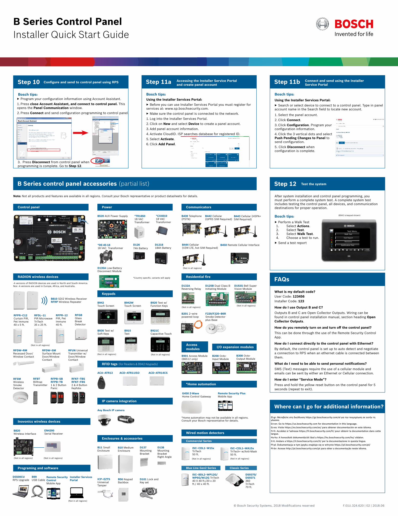
Step 11a
Bosch tips:
Step 12
After system installation and control panel programming, you must perform a complete system test. A complete system test includes testing the control panel, all devices, and communication destinations for proper operation.
Test the system
Bosch tips:
B Series control panel accessories (partial list)
FAQs
Where can I go for additional information?
B520 AUX Power Supply *CX4010 18 VAC Transformer
*TR1850 18 VAC Transformer
D1218 18Ah Battery
D135A Low-Battery Disconnect Module
D126 7Ah Battery
Power Communicators
RADION wireless devices
Keypads
B942W Touch Screen
B920 Text w/ Function Keys
B930 Text w/ Soft Keys
B915 Text
B921C Capacitive Touch
RFID tags (for Readers & B942 Keypads)
Inovonics wireless devices
Programing and software
IP camera integration
Enclosures & accessories
Residential fire
Access modules I/O expansion modules
*Home automation
Wired motion detectors
Blue Line Gen2 Series Classic Series
Step 10
Bosch tips:
Configure and send to control panel using RPS
▶ Program your configuration information using Account Assistant.1. Press close Account Assistant, and connect to control panel. This opens the Panel Communication window.2. Press Connect and send configuration programming to control panel.
Accessing the Installer Service Portal and create panel account
Using the Installer Services Portal: ▶ Before you can use Installer Services Portal you must register for
services at: www.sp.boschsecurity.com. ▶ Make sure the control panel is connected to the network.
1. Log into the Installer Services Portal.2. Click on New and select Device to create a panel account.3. Add panel account information.4. Activate CloudID. ISP searches database for registered ID.5. Select Activate.6. Click Add Panel.
3. Press Disconnect from control panel when programming is complete. Go to Step 12.
*DE-45-18 18 VAC Transformer
*Country specific, variants will apply
(Not in all regions)
(Not in all regions)
(Not in all regions)
(Not in all regions) (Not in all regions)
Step 11b
▶ Search or select device to connect to a control panel. Type in panel account name in the Search field to locate new account.
Bosch tips:
Connect and send using the Installer Service Portal
Using the Installer Services Portal:
B450 Remote Cellular Interface
El-gr: Μεταβείτε στη διεύθυνση https://gr.boschsecurity.com/el για την τεκμηρίωση σε αυτήν τη γλώσσα.En-en: Go to https://us.boschsecurity.com for documentation in this language.Es-es: Visite https://es.boschsecurity.com/es/ para obtener documentación en este idioma.Fr-fr: Accédez à l’adresse https://fr.boschsecurity.com/fr/ pour obtenir la documentation dans cette langue.Hu-hu: A honosított dokumentációt lásd a https://hu.boschsecurity.com/hu/ oldalon.It-it: Andare a https://it.boschsecurity.com/it/ per la documentazione in questa lingua.Pl-pl: Dokumentacja w tym języku znajduje się w witrynie https://pl.boschsecurity.com/pl/Pt-br: Acesse http://pt.boschsecurity.com/pt para obter a documentação neste idioma.
(Not in all regions)
(Not in all regions)
(Not in all regions) (Not in all regions) (Not in all regions)
Installer Services Portal
(Not in all regions)
▶ Perform a Walk Test1. Select Actions.2. Select Test.3. Select Walk Test.4. Choose a test to run. ▶ Send a test report
1. Select the panel account.2. Click Connect.3. Click Configuration. Program your configuration information.4. Click the 3 vertical dots and select Push Pending Changes to Panel to send configuration.5. Click Disconnect when configuration is complete.
© Bosch Security Systems, 2018 Modifications reserved F.01U.324.620 | 02 | 2018.06
Recommended