Information Note
Project: Forth Replacement Crossing Study Job No: 49550TEDT
Subject: Comparison of other Tunnels and Bridges Date: 3rd November 2007
Checked by: Simon James and Chris Dulake Date: 2nd November 2007
Approved by: Ian Dudgeon Date: 6th November 2007 1.0 Introduction As part of the Forth Replacement Crossing Study, Transport Scotland has requested Faber Maunsell to prepare a report with a comparison of tunnels and bridges across the world with the options proposed in Report 4: Appraisal Report. This study will briefly examine the following items:
• Location of tunnel or bridge • Date of construction • Length and size • Construction duration • Cost • Multi-modal capacity • Comparisons with the proposed tunnel or bridge • Photographs
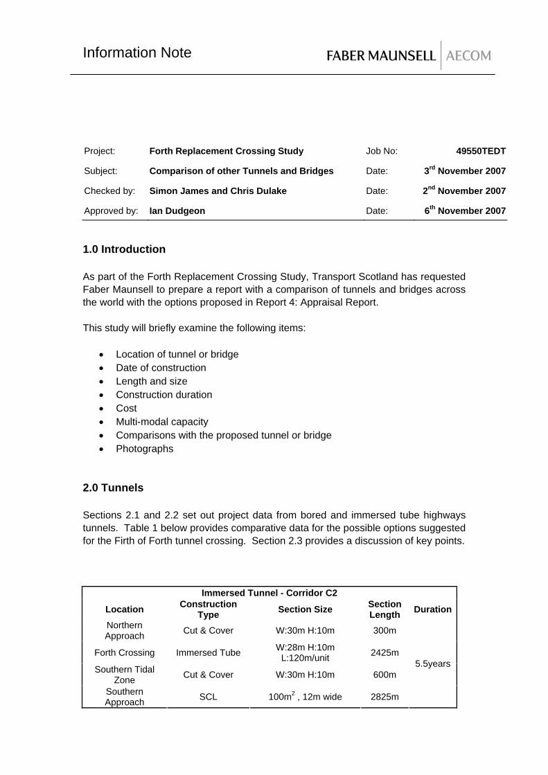
2.0 Tunnels Sections 2.1 and 2.2 set out project data from bored and immersed tube highways tunnels. Table 1 below provides comparative data for the possible options suggested for the Firth of Forth tunnel crossing. Section 2.3 provides a discussion of key points.
Immersed Tunnel - Corridor C2
Location Construction Type Section Size Section
Length Duration Northern Approach Cut & Cover W:30m H:10m 300m
Forth Crossing Immersed Tube W:28m H:10m L:120m/unit 2425m
Southern Tidal Zone Cut & Cover W:30m H:10m 600m
Southern Approach SCL 100m2 , 12m wide 2825m
5.5years
Information Note
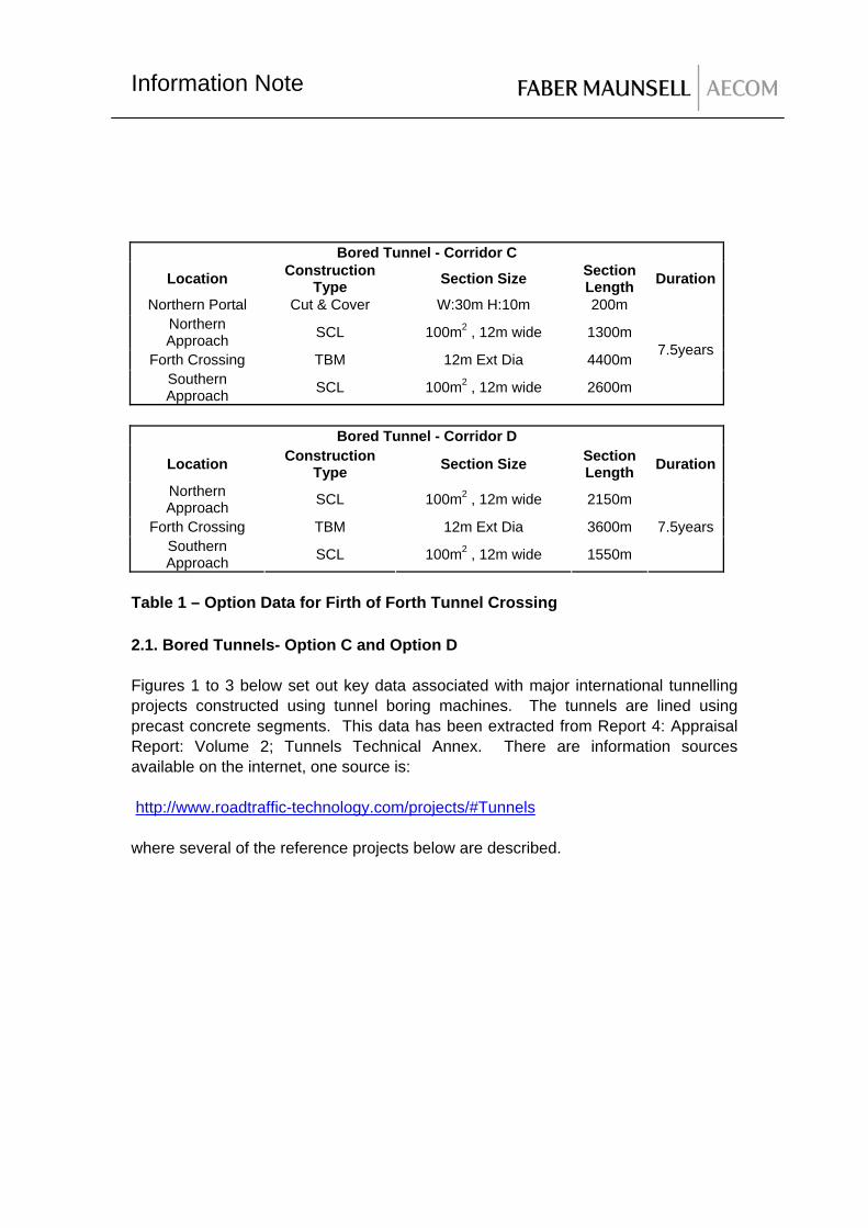
Bored Tunnel - Corridor C
Location Construction Type Section Size Section
Length Duration
Northern Portal Cut & Cover W:30m H:10m 200m Northern Approach SCL 100m2 , 12m wide 1300m
Forth Crossing TBM 12m Ext Dia 4400m Southern Approach SCL 100m2 , 12m wide 2600m
7.5years
Bored Tunnel - Corridor D
Location Construction Type Section Size Section
Length Duration
Northern Approach SCL 100m2 , 12m wide 2150m
Forth Crossing TBM 12m Ext Dia 3600m Southern Approach SCL 100m2 , 12m wide 1550m
7.5years
Table 1 – Option Data for Firth of Forth Tunnel Crossing 2.1. Bored Tunnels- Option C and Option D Figures 1 to 3 below set out key data associated with major international tunnelling projects constructed using tunnel boring machines. The tunnels are lined using precast concrete segments. This data has been extracted from Report 4: Appraisal Report: Volume 2; Tunnels Technical Annex. There are information sources available on the internet, one source is: http://www.roadtraffic-technology.com/projects/#Tunnels where several of the reference projects below are described.

Information Note
Figure 1: TBM Tunnels –external diameters

Information Note
Figure 2: TBM Tunnels –construction programme
Information Note
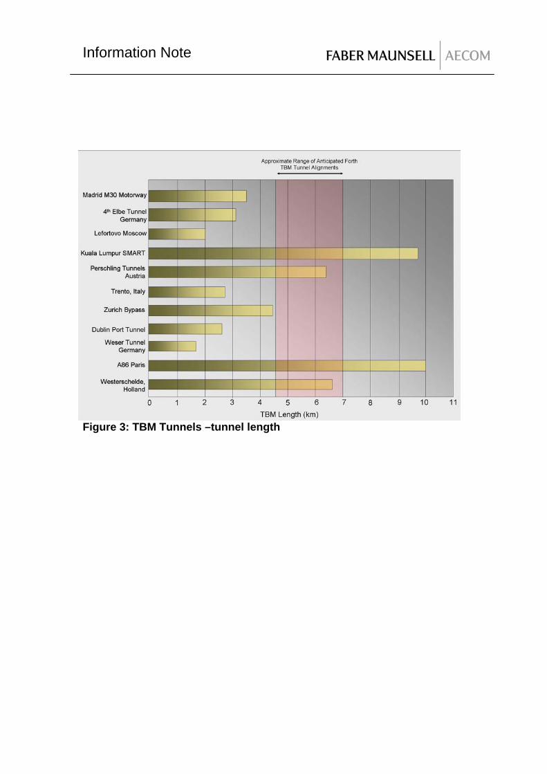
Figure 3: TBM Tunnels –tunnel length

Information Note
PROJECT
DATE COMPLETED COST MULTI-MODAL
Madrid M30 Motorway
Ongoing €792 No
4th Elbe Tunnel
2002 Not available No
Lefortovo, Moscow
2003 Not available No
Kuala Lumpur, SMART
2007 US $514M Multi-functional. Includes storm sewer.
Perschling Tunnels, Austria
Not available Not available No
Trento, Italy
2002 Not available No
Zurich Bypass
Not available Not available No
Dublin Port Tunnel
2006 €752M No
Weser Tunnel, Germany
Not available Not available No
A86 Paris
2007 €2.23Bn No
Westerschelde, Holland
2003 €726M No
Additional Project: Chongming South Channel Tunnel
Ongoing RMB 12.3 Bn Yes, Utilities and light Rail on lower deck
Table 2: TBM Tunnels-other data requested Chongming South Channel Tunnel- Additional information The 7.5 km Chongming South Channel Tunnel will be the world longest bored tunnel underneath water. This tunnel is part of the 25.5 km long Shanghai – Chongming expressway, linking the Changxing and Chongming islands to the city. The expressway consists of the tunnel and a cable bridge from Chang Xing Island to Chongming Island. The tunnel section comprises two 15.3 m OD tunnels, which are the largest TBM tunnels in the world, connected by eight cross passages. The length of each tunnel is approximately 7.5 km and there is a further 1.5 km approach road.
Information Note
The tunnel will be a double-deck tunnel. The upper part will be a three lane city road; the lower part will house the utilities and a light railway. The tunnels will be excavated in soft ground. Ground freezing technique will be used for cross passage construction. Cast iron lining segments will replace the 650 mm thick concrete at the junction between the bored tunnel and cross passage. Maunsell AECOM was appointed as independent consultant to undertake design review of the preliminary designs done by the local design institute and providing expert advice on various technical matters, including civil, geotechnical, structural, electrical and mechanical aspects.

Information Note
Madrid M30 Motorway
Dublin Port Tunnel
A86 Paris

Information Note
Westerschelde, Holland
Additional Project: Chongming South Channel Tunnel
Table 3: Compilation of photographs from the above projects

Information Note
2.2 Immersed Tube Tunnel Table 4 below sets out key data associated with major international immersed tube tunnelling projects. There are fewer examples of this form of road tunnel. The base data has been extracted from Report 4: Appraisal Report: Volume 2; Tunnels Technical Annex.
PROJECT DATE COMPLETED
COST MULTI-MODAL
LENGTH & SIZE L X (H X W X UNIT LENGTH)
CONSTRUCTION PERIOD
Jack Lynch Tunnel Ireland. (Dual two lane)
1999 IR£70M No 1.9km x (8.5m x 24.5m x 120m)
4 years
Ted Williams Tunnel, Boston, USA. (Dual two lane)
1996 Not available No 2.6km x (1.2km underwater) x (6m x 24m x ?)
Not available
Thomassen Tunnel, Netherlands. (Dual Three Lane)
2004 DFL 350,000,000
No 1km x (9m x 34m x ?) 5 years
Warnow Tunnel, Germany. (Dual two lane)
2003 €224M No 790m x (9m x 23m x ?) Not available
Öresund Crossing, Denmark (Dual two lane plus Rail)
1998 DN KR 3.8Bn
Yes Includes cell for light rail.
3.5km x (9m x 41m x 120m)
7 years
Medway Tunnel, UK. (Dual two lane)
1996 £80M No 585m x (9m x 24m x 126)
4.5 years
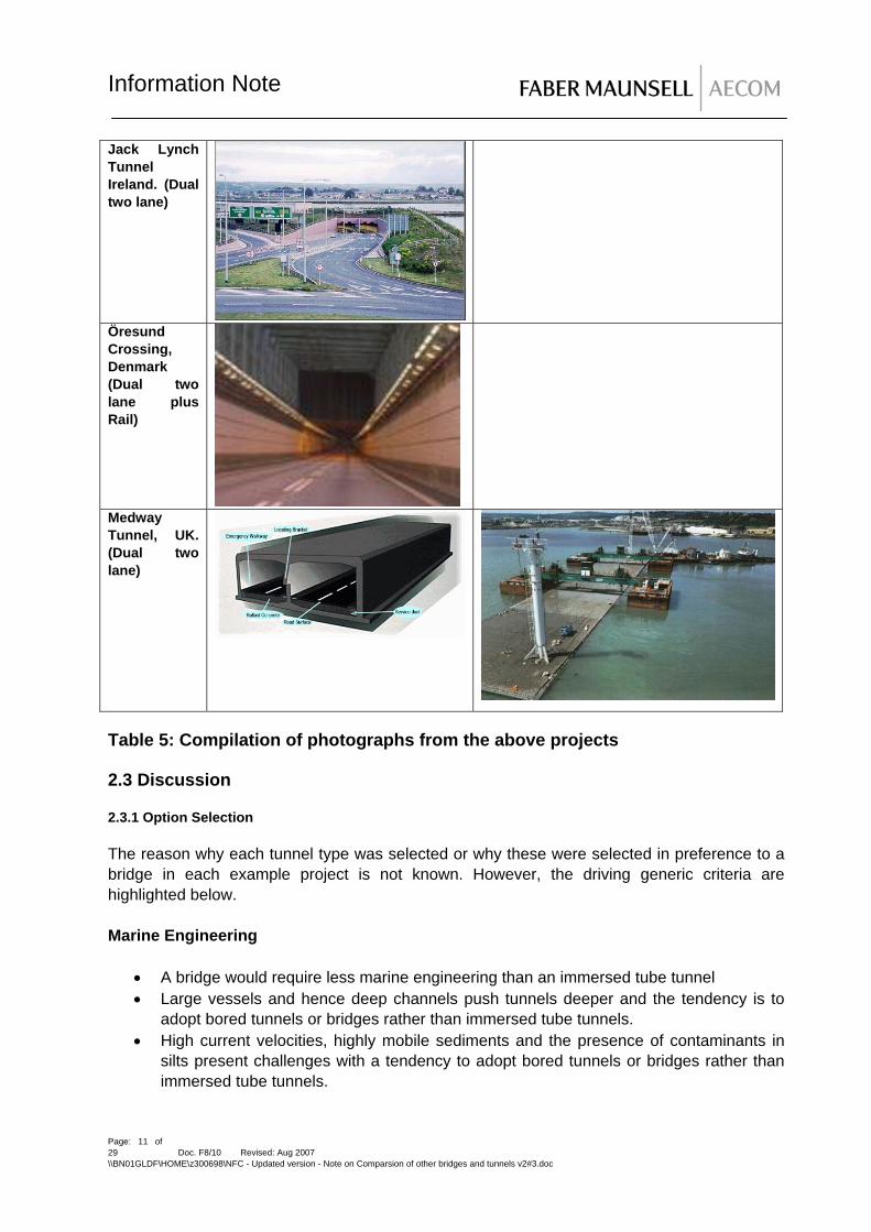
Table 4: Immersed Tube Tunnels
Information Note
Jack Lynch Tunnel Ireland. (Dual two lane)
Öresund Crossing, Denmark (Dual two lane plus Rail)
Medway Tunnel, UK. (Dual two lane)
Table 5: Compilation of photographs from the above projects 2.3 Discussion 2.3.1 Option Selection The reason why each tunnel type was selected or why these were selected in preference to a bridge in each example project is not known. However, the driving generic criteria are highlighted below. Marine Engineering
• A bridge would require less marine engineering than an immersed tube tunnel • Large vessels and hence deep channels push tunnels deeper and the tendency is to
adopt bored tunnels or bridges rather than immersed tube tunnels. • High current velocities, highly mobile sediments and the presence of contaminants in
silts present challenges with a tendency to adopt bored tunnels or bridges rather than immersed tube tunnels.
Page: 11 of 29 Doc. F8/10 Revised: Aug 2007 \\BN01GLDF\HOME\z300698\NFC - Updated version - Note on Comparsion of other bridges and tunnels v2#3.doc

Information Note
• The presence of rock in the marine trenches favours bored tunnels as drill and blast in a marine environment is not recommended and is expensive to execute.
• Bored tunnel in very soft sediments are not favoured as the circular segmental structures can be unstable and less watertight than immersed tube tunnels. Immersed tube tunnels perform well is these materials when they are constructed at shallow depth in low current environments. Bridges have higher founding pressures than immersed tube tunnels and hence can be precluded if ground conditions are poor.
Steepness of Land Fall on either side of the Channel As highway tunnels require maximum gradients to be applied for safety and operational considerations, finding suitable shoreline landing sides is a difficulty for both immersed tube and bored tunnels. Bored tunnel solutions can be excessively long as maximum gradients are defined. This favours immersed tube tunnel solutions. However the approach structures which can be cut and cover, cause significant temporary disturbance at ground level. Bridges overcome the problem associated with steep shorelines and hence alignment gradients. Geology of the Crossing If significant quantities of hard rock are present along the alignment in soft estuarine or marine soils at shallow depth, this may preclude the use of immersed tube tunnels. If the river channel is formed of hard rock with limited marine or estuarine deposits a bored tunnel or bridge would be the preferred choices. If geologically old (consolidated) soft soils are present over the length of the crossing an immersed tube tunnel would be favoured. Environmental Impact A balance will need to be drawn between the impact of the infrastructure in the temporary and permanent conditions. Bored tunnels are likely to pass beneath the channel with no noticeable signs of construction activity. Immersed tube tunnels will have an impact on the shoreline and marine environment but provide overall a shorter and probably cheaper alternative to a bored tunnel. Both generate large quantities of spoil that will need to be disposed of but the final solution is less visually intrusive. Bridges can be iconic, aesthetically pleasing structures but have a higher visual impact than an immersed tube or bored tunnel. Cost of Construction The cost of construction of a bored tunnel per linear meter is cheaper than an immersed tube tunnel but the length of tunnel needed is longer. On balance immersed tube tunnels have a tendency to provide overall, cheaper tunnel solutions. Per linear meter bridges are the cheaper of the three solutions. 2.3.2 Programme Considerations. The length of tunnel, rate of progress of tunnel construction and the overall programme do not necessarily show a consistent pattern. This can be for several reasons:
• Varying geology and hence progress
Page: 12 of 29 Doc. F8/10 Revised: Aug 2007 \\BN01GLDF\HOME\z300698\NFC - Updated version - Note on Comparsion of other bridges and tunnels v2#3.doc

Information Note
• Investment in plant. It is accepted that for shorter tunnels less than 1km the cost of buying bespoke plant is more expensive than accepting low production rates.
• Larger diameter tunnels are driven more slowly smaller ones. • Some project data includes the construction of other infrastructure that cannot be
separated to provide compatible base data. 2.3.3 Double stacked highways The data indicates that double stacked bored tunnels have been adopted. This has only been achieved by compromising the size of vehicles accepted in the tunnel. For example, this is only possible for the A86 in Paris by limiting headroom to 2.1m. This means that only light vans can use the highway, hence precluding lorries. Compromises can be made to achieve a higher number of vehicles using the tunnel but access would need to be restricted. It is understood that for the Firth of Forth crossing lorries will be accepted applying the headroom requirements for the Trans-European Road Network. The maximum size of any bored tunnel in the world is 15.43m external diameter (see section 2.1). At this stage we do not believe that it is possible to double stack highway lanes using the currently defined headroom.
Page: 13 of 29 Doc. F8/10 Revised: Aug 2007 \\BN01GLDF\HOME\z300698\NFC - Updated version - Note on Comparsion of other bridges and tunnels v2#3.doc

Information Note
3.0 Bridges Two bridge forms have been proposed for the Forth Replacement Crossing. One option is a cable stay option with 2 main spans of 650m with its central pylon founded on Beamer Rock. The second option is a Suspension bridge with a main span of 1375m which spans over the Grangemouth and Rosyth navigation channels. Both bridge forms have multi modal capacity. The following table is Table A2 extracted from Report 3 and summarises the major long span bridges with multi modal capacity Long Span Bridges with Rail Loading
Bridge Type Span Rail loading Tsing Ma, Hong Kong Suspension 1377m 2 tracks, medium loading (airport
shuttle trains) Tagus, Lisbon, Portugal
Suspension 1013m 2 tracks, medium loading (passenger & goods)
Minami Bisan-Seto, Japan
Suspension 1100m 2 tracks, provision for 2 tracks for bullet train (See Note 1 below)
Kita Bisan-Seto, Japan
Suspension 990m 2 tracks, provision for 2 tracks for bullet train (See Note 1 below)
Shimotsui-Seto, Japan Suspension 940m 2 tracks, provision for 2 tracks for bullet train (See Note 1 below)
Ohnaruto, Japan Suspension 864m Provision for 2 tracks for bullet train (See Note 1 below)
Rainbow, Japan Suspension 570m 2 tracks, medium loading (passenger)
Øresund, Denmark/Sweden
Cable stayed
490m 2 tracks, heavy loading
Note 1: It is believed that, for these bridges the rail loading is medium to light loading with heavy locomotive. Width of Bridge In the following descriptions of various suspension and cable stay bridges, it can be seen that the width of the bridge varies from bridge to bridge. A comparison of the elements which make up the width is provided for each bridge considered in the following sections wherever this data is available. The width of the bridge depends on several factors, namely:
Page: 14 of 29 Doc. F8/10 Revised: Aug 2007 \\BN01GLDF\HOME\z300698\NFC - Updated version - Note on Comparsion of other bridges and tunnels v2#3.doc
Information Note
• Number and width of traffic lanes. The proposed New Forth Crossing would be Dual 2 with each lane at a width of 3.65m. In many parts of the world, lane widths are slightly less at 3.5m
• Presence of hard shoulder and width. The proposed New Forth Crossing has hard shoulders of 2.75m as stated in Report 4. It is understood that Transport Scotland are exploring the option of increasing the hard shoulder width to 3.3m. In many of the bridges researched for this report, the hard shoulder is significantly less than 2.75m.
• Legislation regarding working widths to safety barriers and central reserve widths. For the New Forth Crossing it was proposed in Report 4 to use a working width of 1.3m. The central reserve is proposed to be 3 m.
• Provision for cyclists/ pedestrians and provision of maintenance access ways. For the New Forth Crossing, an access way with a minimum width of 2.6m has been proposed. This access way will also act as a combined footway/ cycleway. In many of the bridges researched for this report, the access way is significantly reduced with no provision for access vehicles on a separate access way.
• Provision of wind-shielding. It was found during the Setting Forth studies in the mid 1990s that the deck width needed to be increased, if wind-shielding was provided, in order to ensure aerodynamic stability. As noted in Report 3, this extra width is used to accommodate the access way and pedestrian/cycleway noted above.
• Multi-modal capacity. As noted in Report 4, the bridge deck can be modified to provide multi-modal capacity. Report 4 describes how this capacity can be provided by either widening the deck or by providing a double deck solution. The report concluded that the provision of light rapid transit (LRT) at the centre of the bridge would be the most economic and most structurally favourable solution. A double deck solution would keep the deck width to a minimum, but the deck structure would need to be radically changed with the result that the deck would be heavier and would be more expensive. The sides of the deck could be enclosed by a structural cladding system in order to provide a stream-lined shape for aerodynamic stability. In addition ventilation would need to be introduced possibly along the centre-line of the bridge deck. Within the enclosed box emergency access routes would need to be provided either side of the LRT.
3.1 Cable Stay Bridges The table below is Table A3 extracted from Report 3 and summarises the world’s largest cable stay bridges
Page: 15 of 29 Doc. F8/10 Revised: Aug 2007 \\BN01GLDF\HOME\z300698\NFC - Updated version - Note on Comparsion of other bridges and tunnels v2#3.doc

Information Note
World’s Longest Cable Stayed Bridges
Ranking Name Span (m)
Completion Date
Construction Duration (Years)
1 Sutong, China 1088 Expected 2009 2 Stonecutters, HK 1018 Expected 2008 3 Tatara, Japan 890 1999 6 4 Pont de
Normandie, France
856 1995 7
5 Second Yangtze 628 2001 4 6 SkyBridge,
Canada 616 1990 ?
7 Rion-Antirion, Greece
560 2004 6 (including dredging )
8 Skarnsund, Norway
530 1991 ?
9 ohlbrandbrucke, Germany
520 1974 4
10 Mumbai, India 500 3.1.1 Examples of Cable Stay Bridges Rion-Antirion Bridge
Page: 16 of 29 Doc. F8/10 Revised: Aug 2007 \\BN01GLDF\HOME\z300698\NFC - Updated version - Note on Comparsion of other bridges and tunnels v2#3.doc

Information Note
Bridge Data Bridge Location Greece Date and Duration of Construction 1998 – 2004 (6 years) Main Span length (m) 560 Total Bridge Length (m) 2880 including approach spans Bridge Width (m) 27.2 No of Lanes 2 lanes in each direction, narrow (2m)
emergency lanes Original Cost (and currency) 800 million Euros Multi – Modal Capability No
Comparisons between Bridge and Proposed New Forth Crossing The bridge has a direct comparison as it is a multi-span cable stay bridge. The tower type based on an inverted Y is also similar to the proposed scheme. However, the deck construction is a ladder style construction using steel girders composite with concrete slab. The main spans at 560 m are shorter than that proposed for the New Forth Crossing. Comparison of Bridge Width with New Forth Crossing
New Forth Crossing (m) Rion – AntiRion (m) Carriageway 7.3 x 2 =14.6 7.0 x 2 = 14.0 Hard Shoulder/ Strip 2.75 x 2 = 5.5 2.0 x 2 = 4.0 Width for access way, cables 4.9 x 2 = 9.8 (includes space
for access vehicles) 2.85 x 2 = 5.9 (insufficient space for access vehicles
Stream – Lined Shaping 1.2 x 2 = 2.4 0 Central Reserve 3.0 1.5 Set back for Safety Barriers 0.6 x 2 = 1.2 Included in Hard Shoulder Working Width for Safety Barriers
1.3 x 2 = 2.6 0.6 x 2 = 1.2
Edge beams 0.45 x 2 = 0.9 0.4 x 2 = 0.8 Total 40 27.2
Page: 17 of 29 Doc. F8/10 Revised: Aug 2007 \\BN01GLDF\HOME\z300698\NFC - Updated version - Note on Comparsion of other bridges and tunnels v2#3.doc
Information Note
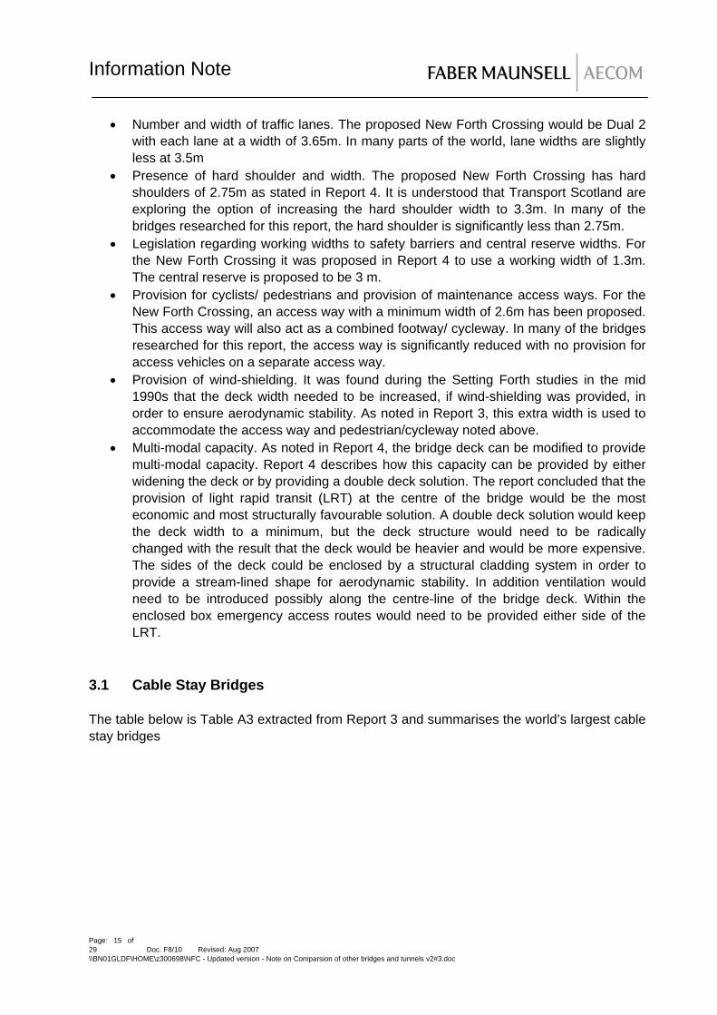
Tatara Bridge Bridge Data
Bridge Location Japan Date and Duration of Construction 1993 – 1999 (6 years) Main Span length (m) 890 Total Bridge Length (m) 1480
Bridge Width (m) 30.6 No of Lanes Original Cost (and currency) Multi – Modal Capability No
Comparisons between Bridge and Proposed New Forth Crossing This bridge is currently (in 2007) the longest span cable stay bridge in the world and is included for comparison. The deck construction is a steel box girder similar to the New Forth Crossing. Each pylon is a twin-legged inverted Y constructed from reinforced concrete. The proposed New Forth Crossing pylons consist of a 4 –legged inverted Y.
Page: 18 of 29 Doc. F8/10 Revised: Aug 2007 \\BN01GLDF\HOME\z300698\NFC - Updated version - Note on Comparsion of other bridges and tunnels v2#3.doc

Information Note
New Forth Crossing (m) Tatara Carriageway 7.3 x 2 =14.6 7.0 x 2 = 14.0 Hard Shoulder/ Strip 2.75 x 2 = 5.5 1.75 x 2 = 3.5 Width for access way, cables 4.9 x 2 = 9.8 (includes space
for access vehicles) 5.04 x 2 = 10.08
Stream – Lined Shaping 1.2 x 2 = 2.4 0 Central Reserve 3.0 2.5 Set back for Safety Barriers 0.6 x 2 = 1.2 Included in access way width Working Width for Safety Barriers
1.3 x 2 = 2.6 Included in access way width
Edge beams 0.45 x 2 = 0.9 0.26 x 2 = 0.52 Total 40 30.6 Oresund Bridge Bridge Data Bridge Location Denmark - Sweden Date and Duration of Construction 1995-1999 (4 years) Main Span length (m) 490 Total Bridge Length (m) 7845 Bridge Width (m) 32 No of Lanes 4 Highway plus 2 Rail Original Cost (and currency) Multi – Modal Capability Yes
Page: 19 of 29 Doc. F8/10 Revised: Aug 2007 \\BN01GLDF\HOME\z300698\NFC - Updated version - Note on Comparsion of other bridges and tunnels v2#3.doc

Information Note
Comparisons between Bridge and Proposed New Forth Crossing The Oresund Bridge has multi-modal capacity. The deck consists of a double deck with highway traffic located on the top level and rail traffic located on the lower level. The main span at 490 m is less than that proposed for the New Forth Crossing. The pylons are H-shaped. Comparison of Bridge Width with New Forth Crossing New Forth Crossing (m) Oresund (m) Carriageway 7.3 x 2 =14.6 7.0 x 2 = 14.0 Hard Shoulder/ Strip 2.75 x 2 = 5.5 2.5 x 2 = 5.0 Width for access way, cables 4.9 x 2 = 9.8 (includes space
for access vehicles) 4.4 x 2 = 8.8
Stream – Lined Shaping 1.2 x 2 = 2.4 0 Central Reserve 3.0 3.0 (Approx) Set back for Safety Barriers 0.6 x 2 = 1.2 Included in Hard Shoulder Working Width for Safety Barriers
1.3 x 2 = 2.6 Included in Hard Shoulder
Edge beams 0.45 x 2 = 0.9 0.6 x 2 = 1.2
Total 40 32 Approx
Kap Shui Mun Bridge
Page: 20 of 29 Doc. F8/10 Revised: Aug 2007 \\BN01GLDF\HOME\z300698\NFC - Updated version - Note on Comparsion of other bridges and tunnels v2#3.doc

Information Note
Bridge Data Bridge Location Hong Kong Date and Duration of Construction 1997 completed Main Span length (m) 430 Total Bridge Length (m) 820 Bridge Width (m) 35.7 No of Lanes 6 lanes plus 2 Rail tracks Original Cost (and currency) Multi – Modal Capability Yes Comparisons between Bridge and Proposed New Forth Crossing The Kap Shui Mun Bridge has multi-modal capacity. The deck consists of a double deck with highway traffic located on the top level and rail traffic located on the lower level. The main span at 430 m is less than that proposed for the New Forth Crossing. The pylons are H – shaped. Comparison of Bridge Width with New Forth Crossing
New Forth Crossing (m) Kap Shui Mun Carriageway 7.3 x 2 =14.6 10.5 x 2 = 21 Hard Shoulder/ Strip 2.75 x 2 = 5.5 2.5 x 2 = 5 Width for access way, cables 4.9 x 2 = 9.8 (includes space
for access vehicles) 2.25 x 2 = 4.5 ( No space for access vehicles)
Stream – Lined Shaping 1.2 x 2 = 2.4 0 Central Reserve 3.0 3.5 Set back for Safety Barriers 0.6 x 2 = 1.2 0.6 x 2 = 1.2 Working Width for Safety Barriers
1.3 x 2 = 2.6 Included in carriageway width
Edge beams 0.45 x 2 = 0.9 0.25 x 2 = 0.5 Total 40 35.7
Page: 21 of 29 Doc. F8/10 Revised: Aug 2007 \\BN01GLDF\HOME\z300698\NFC - Updated version - Note on Comparsion of other bridges and tunnels v2#3.doc
Information Note
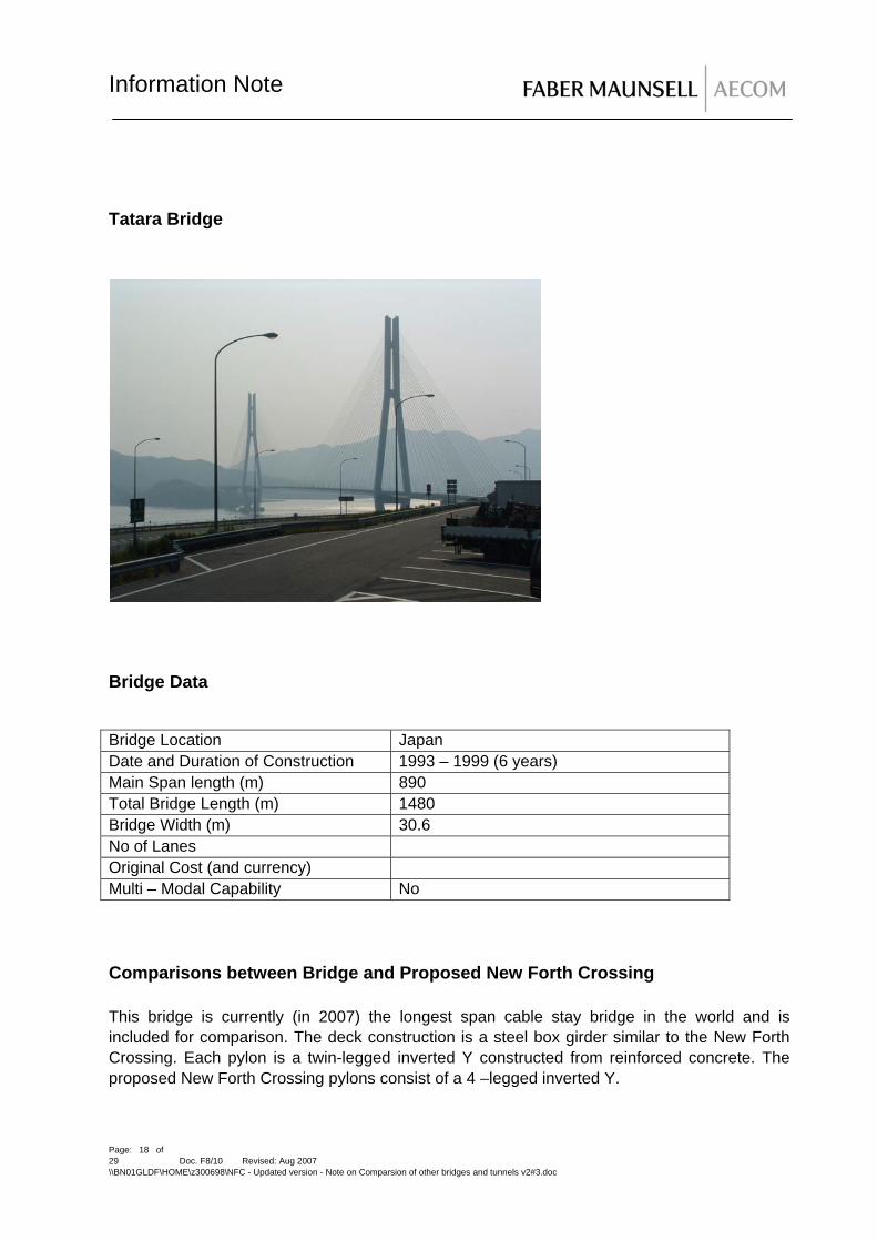
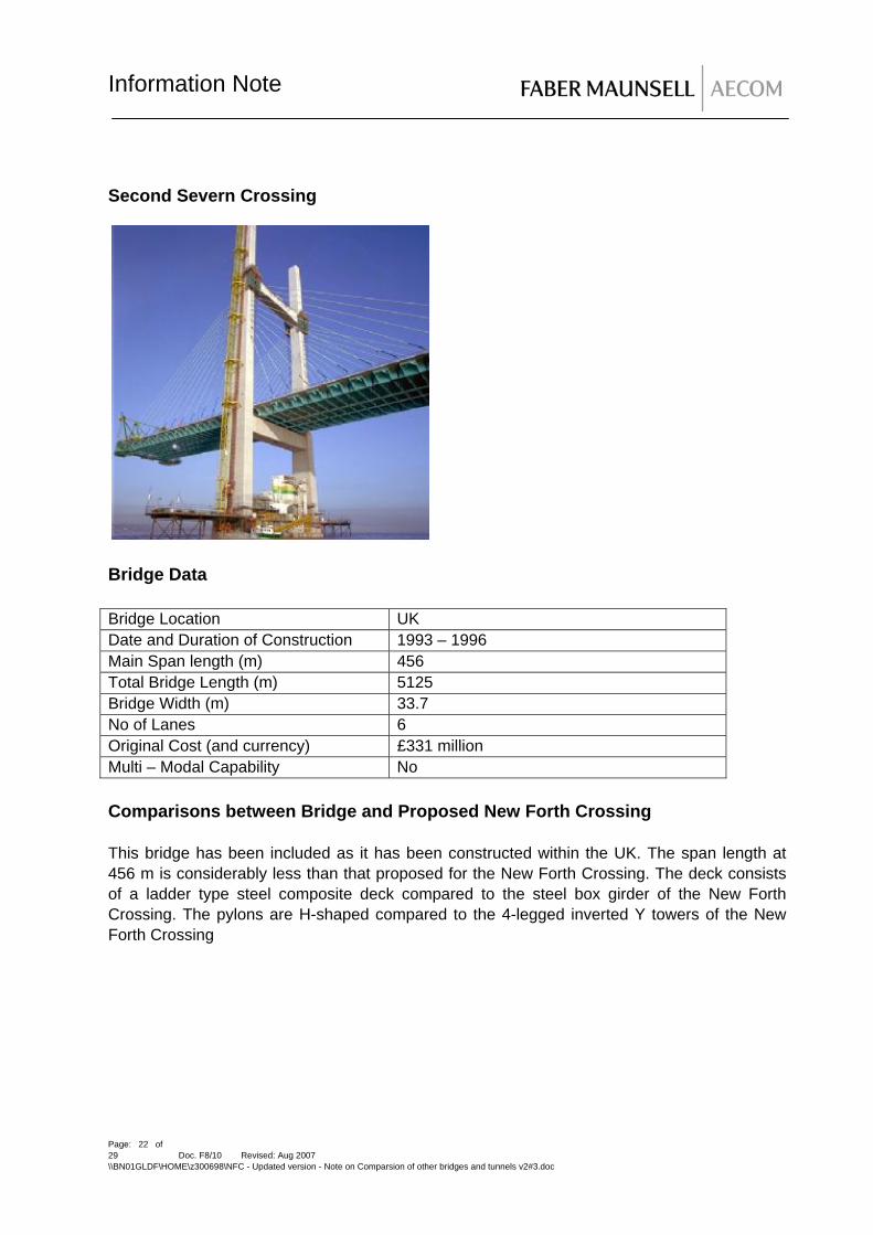
Second Severn Crossing Bridge Data Bridge Location UK Date and Duration of Construction 1993 – 1996 Main Span length (m) 456 Total Bridge Length (m) 5125 Bridge Width (m) 33.7 No of Lanes 6 Original Cost (and currency) £331 million Multi – Modal Capability No Comparisons between Bridge and Proposed New Forth Crossing This bridge has been included as it has been constructed within the UK. The span length at 456 m is considerably less than that proposed for the New Forth Crossing. The deck consists of a ladder type steel composite deck compared to the steel box girder of the New Forth Crossing. The pylons are H-shaped compared to the 4-legged inverted Y towers of the New Forth Crossing
Page: 22 of 29 Doc. F8/10 Revised: Aug 2007 \\BN01GLDF\HOME\z300698\NFC - Updated version - Note on Comparsion of other bridges and tunnels v2#3.doc

Information Note
Comparison of Bridge Width with New Forth Crossing New Forth Crossing (m) Second Severn Carriageway 7.3 x 2 =14.6 10.1 x 2 = 20.2 Hard Shoulder/ Strip 2.75 x 2 = 5.5 2.6 x 2 = 5.2 Width for access way, cable clearance
4.9 x 2 = 9.8 (includes space for access vehicles)
2.1 x 2 = 4.2
Stream – Lined Shaping 1.2 x 2 = 2.4 0 Central Reserve 3.0 2.0 Set back for Safety Barriers 0.6 x 2 = 1.2 0.6 x 2 = 1.2 Working Width for Safety Barriers
1.3 x 2 = 2.6 Included in cable clearance
Edge beams 0.45 x 2 = 0.9 0.45 x 2 = 0.9
Total 40 33.7
3.2 Suspension Bridges The following table is Table A1 extracted from Report 3 and summarises the world’s largest suspension bridges.
World’s Longest Suspension Bridges
Ranking Name Main Span (m)
Completion Date
Construction Duration (Years)
1 Akashi-Kaikyo, Japan
1991 1998 10
2 Great Belt Bridge, Denmark
1624 1998 7
3 Runyang, China 1490 2005 5 4 Humber, UK 1410 1981 8 5 Jiangyin, China 1385 1999 5 6 Tsing Ma, HK 1377 1997 5 7 Verrazano
Narrows, USA 1298 1964 5
8 Golden Gate,USA
1280 1937 4
9 High Coast, Sweden
1210 1997 4
10 Mackinac, USA 1158 1957 2.5
Page: 23 of 29 Doc. F8/10 Revised: Aug 2007 \\BN01GLDF\HOME\z300698\NFC - Updated version - Note on Comparsion of other bridges and tunnels v2#3.doc

Information Note
In addition to the list above, the following suspension bridges are at the construction, planning phases or have recently been completed:
Name Main Span (m)
Completion Date
Phase
1 Messina, Italy 3300 Planning 2 Chacao, Chile 1100 Planning 3 Tacoma
Narrows, USA 853 2007 Completed
4 Carquinez, USA 1056 2003 Completed 5 East Bay, USA 385 Under
construction 6 Hardanger,
Norway 1200 Planning
Various other suspension bridges are also in the planning phase in Japan and South Korea. It can be noted from the above table that modern suspension bridges are generally considered where the clear main span is greater than 1000m. The maximum span that can be achieved by a cable stay bridge is now in excess of 1000m and cable stay bridges can compete economically with a suspension bridge up to this span. 3.2.1 Examples of Suspension Bridges Tsing Ma Bridge
Page: 24 of 29 Doc. F8/10 Revised: Aug 2007 \\BN01GLDF\HOME\z300698\NFC - Updated version - Note on Comparsion of other bridges and tunnels v2#3.doc

Information Note
Bridge Data Bridge Location Hong Kong Date and Duration of Construction 1992 – 1997 (5 Years) Main Span length (m) 1377 Total Bridge Length (m) 2160 Bridge Width (m) 41 No of Lanes 6 lanes plus 2 Rail Original Cost (and currency) 880 US$ Multi – Modal Capability Yes Comparisons between Bridge and Proposed New Forth Crossing The proposed span is equivalent to the proposed Suspension Bridge span for the New Forth Crossing. The deck construction consisting of a box girder is similar to the New Forth Crossing. Comparison of Bridge Width with New Forth Crossing New Forth Crossing (m) Tsing Ma Carriageway 7.3 x 2 =14.6 11.0 (assumed) x 2 = 22.0 Hard Shoulder/ Strip 2.75 x 2 = 5.5 2.0 (assumed) x 2 = 4.0 Width for access way, cable clearance
4.9 x 2 = 9.8 (includes space for access vehicles)
Stream – Lined Shaping 1.2 x 2 = 2.4 4.5 (assumed) x 2 = 9.0 Central Reserve 3.0 6.0 (assumed) including
offside hard strip Set back for Safety Barriers 0.6 x 2 = 1.2 Included in hard shoulder Working Width for Safety Barriers
1.3 x 2 = 2.6 Included in hard shoulder
Edge beams 0.45 x 2 = 0.9 included
Total 40 41.0
Page: 25 of 29 Doc. F8/10 Revised: Aug 2007 \\BN01GLDF\HOME\z300698\NFC - Updated version - Note on Comparsion of other bridges and tunnels v2#3.doc

Information Note
Jiang Yin Bridge Bridge Data Bridge Location China Date and Duration of Construction 1995 - 1999 Main Span length (m) 1385 Total Bridge Length (m) Approx 3000 Bridge Width (m) No of Lanes 6 lanes Original Cost (and currency) 495 US$ Multi – Modal Capability No Comparisons between Bridge and Proposed New Forth Crossing The main span is approximately equal to the proposed New Forth Crossing suspension bridge.
Page: 26 of 29 Doc. F8/10 Revised: Aug 2007 \\BN01GLDF\HOME\z300698\NFC - Updated version - Note on Comparsion of other bridges and tunnels v2#3.doc

Information Note
Comparison of Bridge Width with New Forth Crossing
New Forth Crossing (m) Jiang Yin Carriageway 7.3 x 2 =14.6 14.0 x 2 = 28.0 Hard Shoulder/ Strip 2.75 x 2 = 5.5 Included in carriageway Width for access way, cable clearance
4.9 x 2 = 9.8 (includes space for access vehicles)
2.2 x 2 = 4.4
Stream – Lined Shaping 1.2 x 2 = 2.4 1.5 x 2 = 3.0 Central Reserve 3.0 1.5 Set back for Safety Barriers 0.6 x 2 = 1.2 Included in carriageway Working Width for Safety Barriers
1.3 x 2 = 2.6 Included in carriageway
Edge beams 0.45 x 2 = 0.9 Included in access way
Total 40 36.9
Humber Bridge Bridge Data Bridge Location UK Date and Duration of Construction 1972 – 1981 (8 years) Main Span length (m) 1410 Total Bridge Length (m) 2220 Bridge Width (m) 28.5 No of Lanes 4 Original Cost (and currency) £ 98 million Multi – Modal Capability No Comparisons between Bridge and Proposed New Forth Crossing This UK bridge has a main span slightly greater than that proposed for the New Forth Crossing suspension bridge.
Page: 27 of 29 Doc. F8/10 Revised: Aug 2007 \\BN01GLDF\HOME\z300698\NFC - Updated version - Note on Comparsion of other bridges and tunnels v2#3.doc

Information Note
Comparison of Bridge Width with New Forth Crossing New Forth Crossing (m) Humber Carriageway 7.3 x 2 =14.6 7.3 x 2 = 14.6 Hard Shoulder/ Strip 2.75 x 2 = 5.5 0.8 x 2 = 1.6 Width for access way, cable clearance
4.9 x 2 = 9.8 (includes space for access vehicles)
3.0 x 2 = 6.0
Stream – Lined Shaping 1.2 x 2 = 2.4 1.9 x 2 = 3.8 Central Reserve 3.0 2.0 Set back for Safety Barriers 0.6 x 2 = 1.2 Included in hard strip Working Width for Safety Barriers
1.3 x 2 = 2.6 included
Edge beams 0.45 x 2 = 0.9 0.25 x 2 = 0.5
Total 40 28.5
Minami Bisan Seto Bridge Data Bridge Location Japan Date and Duration of Construction Completed 1988 Main Span length (m) 1100 Total Bridge Length (m) 1723 Bridge Width (m) 37.0 (approx) No of Lanes Highway bridge includes 2 rail tracks and
provision for 2 further rail tracks
Page: 28 of 29 Doc. F8/10 Revised: Aug 2007 \\BN01GLDF\HOME\z300698\NFC - Updated version - Note on Comparsion of other bridges and tunnels v2#3.doc

Information Note
Original Cost (and currency) Multi – Modal Capability Yes Comparisons between Bridge and Proposed New Forth Crossing The main span is less than that proposed for the New Forth Crossing. The bridge carries highway and rail traffic. Comparison of Bridge Width with New Forth Crossing
New Forth Crossing (m) Minami Bisan Seto Carriageway 7.3 x 2 =14.6 7.0 x 2 = 14.0 Hard Shoulder/ Strip 2.75 x 2 = 5.5 2.5 x 2 = 5.0 Width for access way, cable clearance
4.9 x 2 = 9.8 (includes space for access vehicles)
6.25 x 2 = 12.5
Stream – Lined Shaping 1.2 x 2 = 2.4 0 Central Reserve 3.0 3.5 Set back for Safety Barriers 0.6 x 2 = 1.2 included Working Width for Safety Barriers
1.3 x 2 = 2.6 Included
Edge beams 0.45 x 2 = 0.9 1.0 x 2 = 2.0 (approx) Total 40 37.0 (approx)
Page: 29 of 29 Doc. F8/10 Revised: Aug 2007 \\BN01GLDF\HOME\z300698\NFC - Updated version - Note on Comparsion of other bridges and tunnels v2#3.doc
Recommended