INSTALLATION INSTRUCTIONSfor Economizer (NPECOMZR006A00)ICP
Manufacturer reserves the right to discontinue, or change at any time, specifications, designs and prices without notice and without incurring obligations. Form No. 5052-1P Copyright MicroMetl Corporation 2007. All rights reserved.
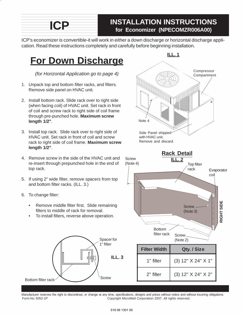
ICP's economizer is convertible-it will work in either a down discharge or horizontal discharge appli-cation. Read these instructions completely and carefully before beginning installation.
For Down Discharge(for Horizontal Application go to page 4)
ILL. 1
CompressorCompartment
Rack DetailILL. 2
Side Panel shippedwith HVAC unit.Remove and discard.
Spacer for1" filter
ScrewBottom filter rack
ILL. 3htdiWretliF eziS/.ytQ
retlif"1 "1X"42X"21)3(
retlif"2 "2X"42X"21)3(
1. Unpack top and bottom filter racks, and filters.Remove side panel on HVAC unit.
2. Install bottom rack. Slide rack over to right side(when facing coil) of HVAC unit. Set rack in frontof coil and screw rack to right side of coil framethrough pre-punched hole. Maximum screwlength 1/2".
3. Install top rack. Slide rack over to right side ofHVAC unit. Set rack in front of coil and screwrack to right side of coil frame. Maximum screwlength 1/2".
4. Remove screw in the side of the HVAC unit andre-insert through prepunched hole in the end oftop rack.
5. If using 2" wide filter, remove spacers from topand bottom filter racks. (ILL. 3.)
6. To change filter:
• Remove middle filter first. Slide remainingfilters to middle of rack for removal.
• To install filters, reverse above operation.
Screw(Note 4)
Screw(Note 3)
Top filterrack
Bottomfilter rack Screw
(Note 2)
RIG
HT
SID
E
Evaporatorcoil
Note 4
519 06 1301 00

DownDischarge
2
Install 3/4" x 1/8"gasket alongdivider flange
Divider w/HVAC unit
Install 3/4" x 1/8"gasket alongeconomizer bottom
1/2" flange
3/8"flange
Install additional screwthrough HVAC unit flange intoreplacement panel.
Coil
Divider
ReliefBlade Damper
actuator
Add 3/4" x 1/8"gasket here.
GasketTop View
Detail
Alignment Holes
Horizontal filteraccess door
ILL.5
Replacement panel.Shipped witheconomizer
MicroMetleconomizer
7. Install the replacement panel (shipped with the economizer) over the compressor compartment of theHVAC unit. Screw in place through the prepunched holes.
NOTE: Top left hole will need to be field drilled. See ILL. 5.
8. Slide the economizer into the return air chamber, ILL. 5. Slide the economizer as far to the left as possible.The economizer's right side will slightly overlap the bottom filter rack. Be sure economizer is flat.
9. Install 3/4 x 1/8 gasket to bottom flange of economizer, see detail. Install gasket to HVAC unit divider.See detail.
10.Route the economizer wiring harness through the grommet in the economizer side (ILL. 5) and throughthe HVAC units provided hole located in the upper part of the HVAC unit divider. (Install provided grom-met in divider hole of HVAC unit. Follow the included harness routing diagram. (see page 9)
11. Install the economizer cover panel over the economizer. Slide panel underneath HVAC unit flange. Screwin place to the divider in the HVAC unit, base and top. Also, align economizers 3/8" flange to the outsideof 1/2" flange as shown and secure economizer cover panel to economizer using provided pre-punchedalignment holes with 1" long tek screw.
28 ½"
Economizercover panel
13 7 / 16"
23 7/16"
23 9/16"
519 06 1301 00

DownDischarge
3
14 1”8
ILL. 6
ILL. 7
TOP VIEW ILL. 8
Replacementpanel
Filter accessdoor - hinged
13. After adjusting the minimum position setting onthe actuator, screw the rainhood to the econo-mizer panel through the prepunched holes. Thetop flange of the hood slips underneath the HVACunit flange. Caulk hood perimeter. Install thealuminum filter in the rain hood.
14. Remove the cover panel shipped over thehorizontal return opening. Locate the filteraccess panel and door latch. Install door latchangle. Screw the hinge to the HVAC unit overthe horizontal return opening. Adjust the closurehandles for a tight seal. Install the provided filteraccess sticker on the hinged door.
Compressor
Coil
ReplacementPanelEconomizer
Hood
0"
Filterrack
Hinge
Door latchangle
Install filteraccess doorsticker
Horizontal supplyair cover panel.Shipped on HVACunit.
13. Be sure the seams are all water tight. Seal asrequired.
14. Follow the wiring instructions enclosed.(see page 7,8)
Filters
Rainhood
SIDE VIEWDown Discharge
Screw
Unit panel
Door latchangle
DOOR LATCH ANGLEDETAIL
"
Aluminum waterentrainment filter(23 7/8" x 17 1/2" x 2")
Rainhood
519 06 1301 00
HorizontalDischarge
4
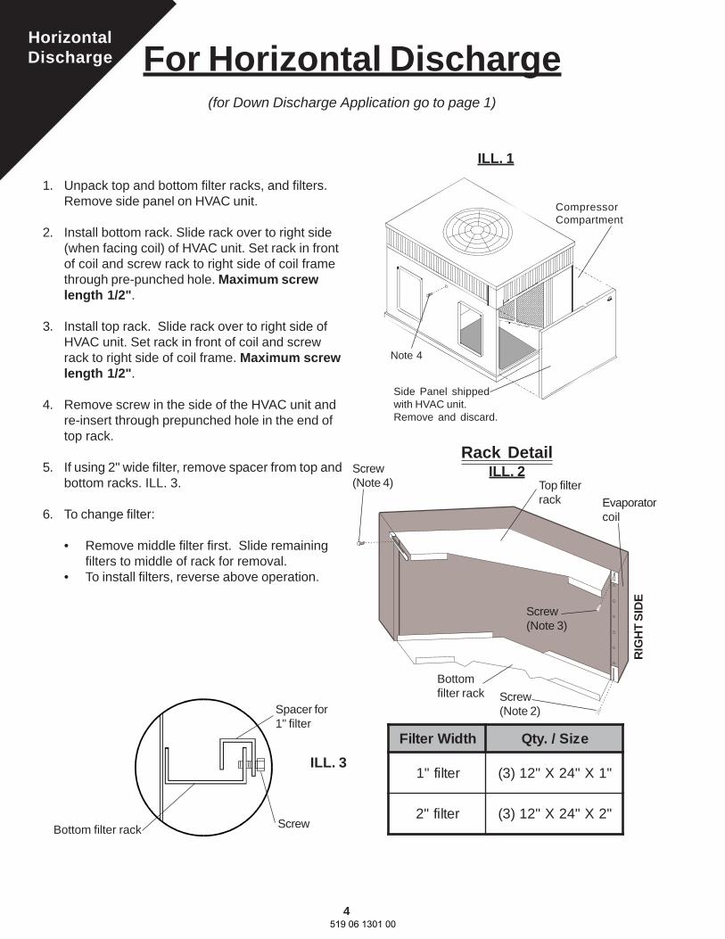
For Horizontal Discharge(for Down Discharge Application go to page 1)
ILL. 1
CompressorCompartment
Rack DetailILL. 2
Side Panel shippedwith HVAC unit.Remove and discard.
Spacer for1" filter
ScrewBottom filter rack
ILL. 3htdiWretliF eziS/.ytQ
retlif"1 "1X"42X"21)3(
retlif"2 "2X"42X"21)3(
1. Unpack top and bottom filter racks, and filters.Remove side panel on HVAC unit.
2. Install bottom rack. Slide rack over to right side(when facing coil) of HVAC unit. Set rack in frontof coil and screw rack to right side of coil framethrough pre-punched hole. Maximum screwlength 1/2".
3. Install top rack. Slide rack over to right side ofHVAC unit. Set rack in front of coil and screwrack to right side of coil frame. Maximum screwlength 1/2".
4. Remove screw in the side of the HVAC unit andre-insert through prepunched hole in the end oftop rack.
5. If using 2" wide filter, remove spacer from top andbottom racks. ILL. 3.
6. To change filter:
• Remove middle filter first. Slide remainingfilters to middle of rack for removal.
• To install filters, reverse above operation.
Screw(Note 4)
Screw(Note 3)
Top filterrack
Bottomfilter rack Screw
(Note 2)
RIG
HT
SID
E
Evaporatorcoil
Note 4
519 06 1301 00
HorizontalDischarge
5
Coil
Divider
Gasket
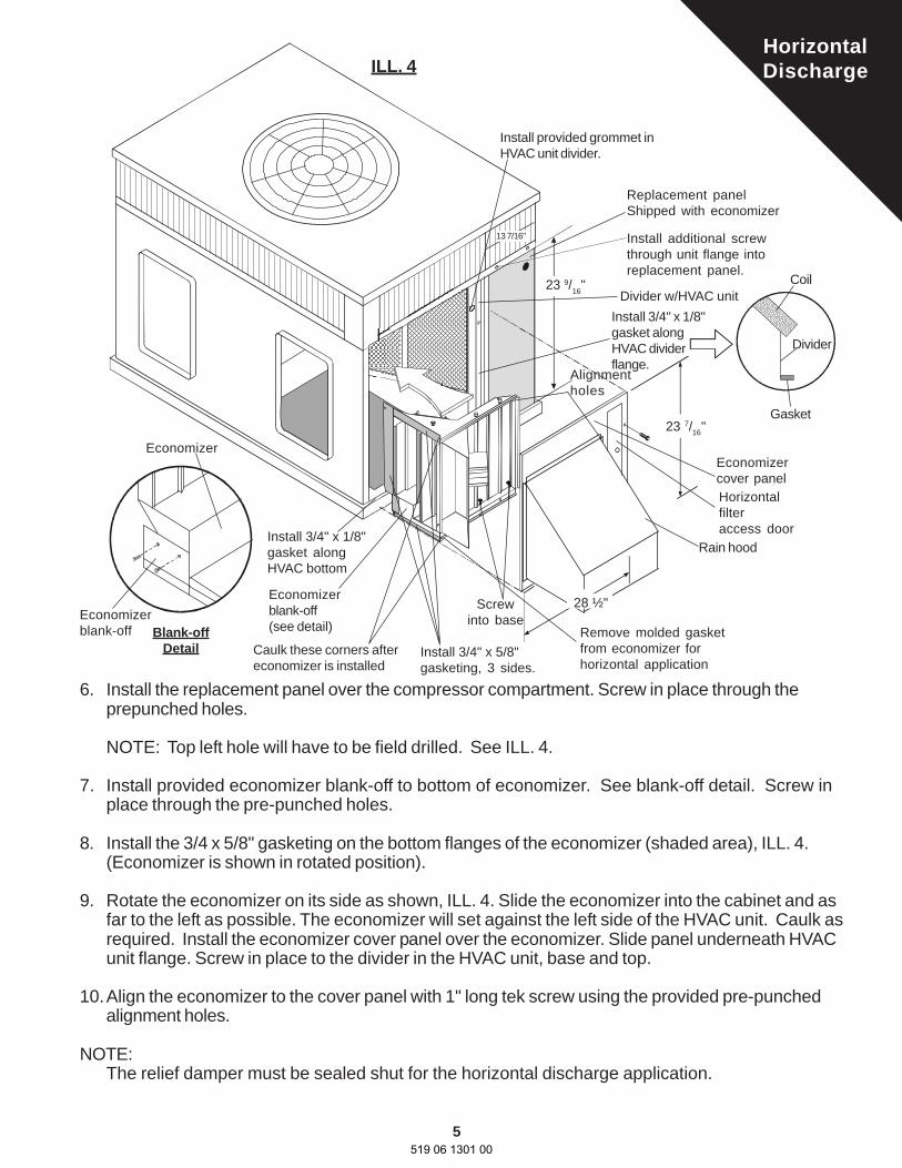
6. Install the replacement panel over the compressor compartment. Screw in place through theprepunched holes.
NOTE: Top left hole will have to be field drilled. See ILL. 4.
7. Install provided economizer blank-off to bottom of economizer. See blank-off detail. Screw inplace through the pre-punched holes.
8. Install the 3/4 x 5/8" gasketing on the bottom flanges of the economizer (shaded area), ILL. 4.(Economizer is shown in rotated position).
9. Rotate the economizer on its side as shown, ILL. 4. Slide the economizer into the cabinet and asfar to the left as possible. The economizer will set against the left side of the HVAC unit. Caulk asrequired. Install the economizer cover panel over the economizer. Slide panel underneath HVACunit flange. Screw in place to the divider in the HVAC unit, base and top.
10.Align the economizer to the cover panel with 1" long tek screw using the provided pre-punchedalignment holes.
NOTE:The relief damper must be sealed shut for the horizontal discharge application.
Replacement panelShipped with economizer
Screwinto base
Economizercover panel
28 ½"
ILL. 4
Caulk these corners aftereconomizer is installed
13 7/16"
Economizerblank-off(see detail)
Install 3/4" x 1/8"gasket alongHVAC bottom
23 7/16"
Divider w/HVAC unit
Install additional screwthrough unit flange intoreplacement panel.
Install 3/4" x 1/8"gasket alongHVAC dividerflange.
Horizontalfilteraccess door
23 9/16"
Rain hood
Install provided grommet inHVAC unit divider.
Economizer
Economizerblank-off Blank-off
Detail Install 3/4" x 5/8"gasketing, 3 sides.
Alignmentholes
Remove molded gasketfrom economizer forhorizontal application
519 06 1301 00
HorizontalDischarge
6
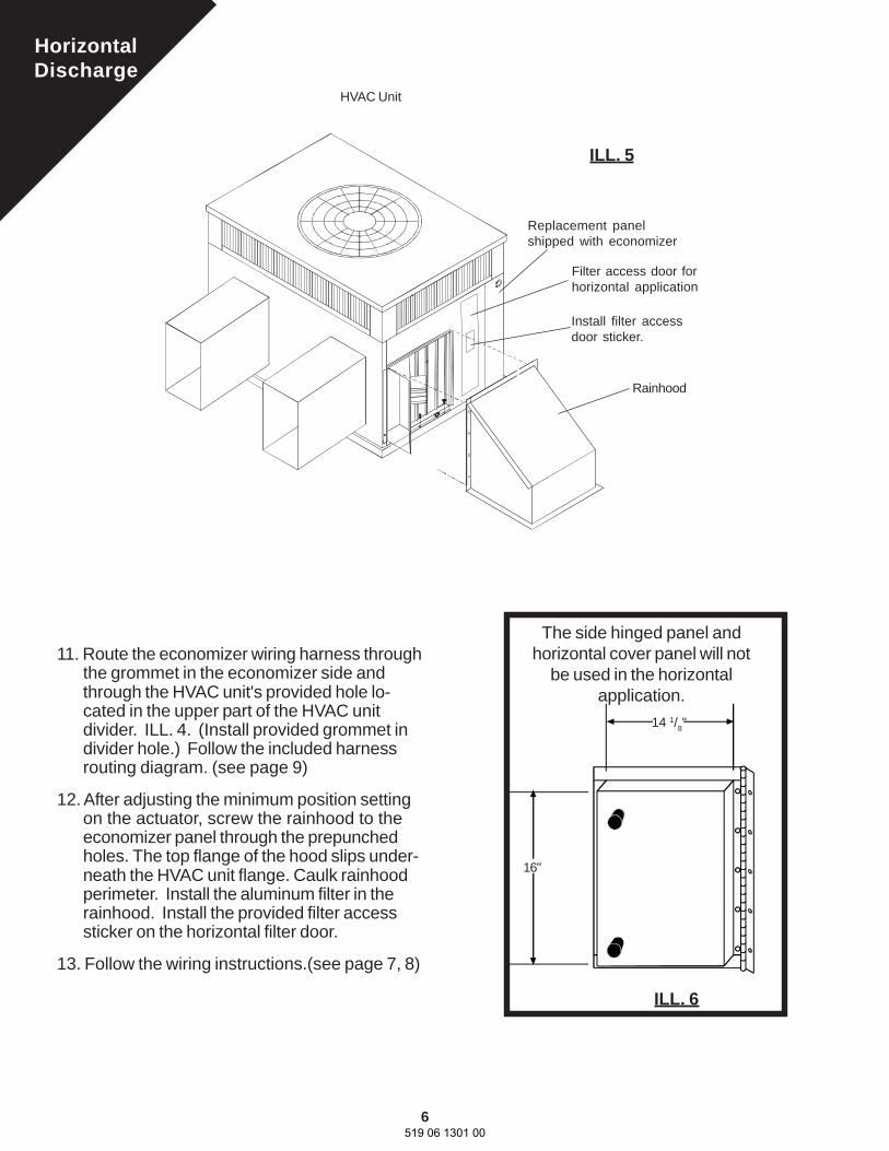
Install filter accessdoor sticker.
11. Route the economizer wiring harness throughthe grommet in the economizer side andthrough the HVAC unit's provided hole lo-cated in the upper part of the HVAC unitdivider. ILL. 4. (Install provided grommet individer hole.) Follow the included harnessrouting diagram. (see page 9)
12. After adjusting the minimum position settingon the actuator, screw the rainhood to theeconomizer panel through the prepunchedholes. The top flange of the hood slips under-neath the HVAC unit flange. Caulk rainhoodperimeter. Install the aluminum filter in therainhood. Install the provided filter accesssticker on the horizontal filter door.
13. Follow the wiring instructions.(see page 7, 8)
ILL. 6
ILL. 5
Filter access door forhorizontal application
HVAC Unit
Replacement panelshipped with economizer
Rainhood
14 1/8"
16"
The side hinged panel andhorizontal cover panel will not
be used in the horizontalapplication.
519 06 1301 00

7
2
WIRING LEGEND
Terminals
Wire nut or equivalent connection
MMC wiring harness
Field supplied low voltage wire
Field supplied high voltage wire
Other low voltage wire
OrangeGreen
Wiring Diagram For Economizers with Heat Pump
Y2
3
WHITE
YEL.
P
3
T
4
5
2
P1
T1
P
P1
T1
T
TR1
TR24 VAC
resistor620
Gray
Economizer
Gray4
2K
1K1S
5
EquipmentTransformer Main 24V
Splice Box
Optional RemotePotentiometer
Dry Bulb OutsideAir Sensor(or optional enthalpy)
Form No. 2931-2PW2
Discharge Sensor
1S1
THERMOSTAT
TR TR1
+
+
1
ACTUATOR
RED
BLUE
L1L2
11R1
11
11
Min.Pos
Dis
char
geSe
nsor
Min
imum
Posi
tion
OPTIONAL LOW AMBIENT CONTROL.EQUIPMENT TRANSFORMER MUST BE SIZED TO ACCOMMO-DATE AN ADDITIONAL 12VA. IF NOT, AN ADDITIONALOPTIONAL TRANSFORMER IS REQUIRED.POWER SUPPLY. DISCONNECT MEANS AND OVERLOADPROTECTION AS REQUIRED.MUST BE INSTALLED IN SUPPLY AIR STREAM. 3000 OHMSAT 25ºC, 77ºFREMOVE JUMPER WHEN OPTIONAL REMOTE POTENTIOM-ETER IS USED1S IS AN ELECTRONIC SWITCH WHICH CLOSES WHENPOWERED BY A 24 VAC INPUT.RELAY 1K & 2K ACTUATE WHEN THE OUTSIDE AIR SENSEDBY THE ENTHALPY OR DRY BULB IS LOWER THAN THE SETPOINT A-D.FACTORY INSTALLED 620 OHM, 1 WATT, 5% RESISTORSHOULD BE REMOVED ONLY IF AN ENTHALPY OR ADJUST-ABLE DRY BULB SENSOR IS ADDED TO SR AND + FORDIFFERENTIAL.RESISTOR ONLY REQUIRED FOR FIXED DRY BULB.R1- RELAY IS FACTORY SUPPLIED AND FIELD INSTALLED.MOUNT RELAY IN CONTROL BOX, ABOVE INDOOR FANRELAY.
NOTES:
61. Disconnect power supply beforeconnecting wiring to prevent electricalshock or equipment damage
CAUTION
+s
6SR
SO 8
7
R G Y1W1W2
L
R1N.O.
R1
2
3
4
7
8
11
1
VOILET
GREEN
BROWN
YELLOW
RED
ORANGE
9resistor
O
1
5
9
519 06 1301 00
CC
1FR
HC
OrangeGreen
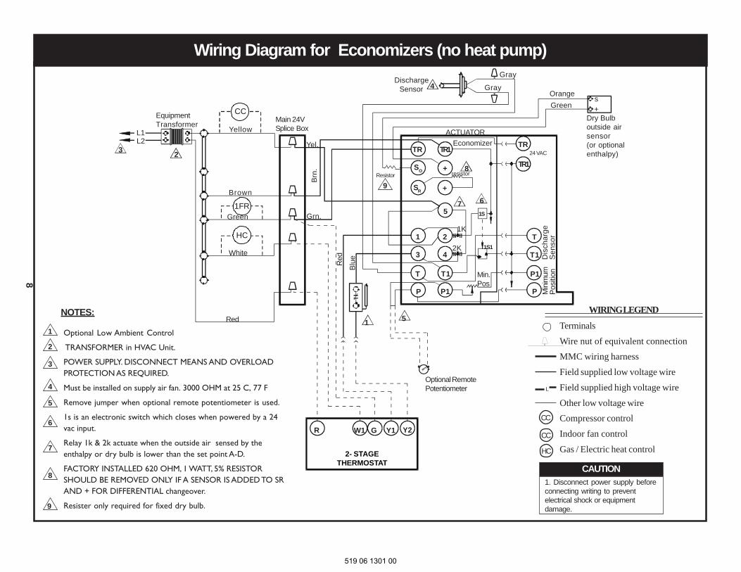
Wiring Diagram for Economizers (no heat pump)
2- STAGETHERMOSTAT
R G Y1 Y2W1
23
Grn.
Brn
.
Yel.
Red
Blue
TR
SR
SO
TR1
+
+
P
3
1
T
4
5
2
P1
T1
P
P1
T1
T
TR1
TR24 VAC
resistor8
Discharge Sensor Gray
EconomizerACTUATOR
Gray4
+s
2K
1K
1S
1S1
67
5
Min.Pos
1NOTES:
EquipmentTransformer
Main 24VSplice Box
Optional RemotePotentiometer
Dry Bulboutside airsensor(or optionalenthalpy)
2
3
4
5
6
7
8
WIRING LEGEND
Terminals
Wire nut of equivalent connectionMMC wiring harness
Field supplied low voltage wire
Field supplied high voltage wire
Other low voltage wireCompressor control
Indoor fan control
Gas / Electric heat control
L
1. Disconnect power supply beforeconnecting writing to preventelectrical shock or equipmentdamage.
CAUTION
L2L1 Yellow
Green
Brown
White
Red
Min
imum
Posi
tion
Dis
char
geS
enso
r
Optional Low Ambient Control
TRANSFORMER in HVAC Unit.
POWER SUPPLY. DISCONNECT MEANS AND OVERLOADPROTECTION AS REQUIRED.
Must be installed on supply air fan. 3000 OHM at 25 C, 77 F
Remove jumper when optional remote potentiometer is used.
1s is an electronic switch which closes when powered by a 24vac input.
Relay 1k & 2k actuate when the outside air sensed by theenthalpy or dry bulb is lower than the set point A-D.
FACTORY INSTALLED 620 OHM, 1 WATT, 5% RESISTORSHOULD BE REMOVED ONLY IF A SENSOR IS ADDED TO SRAND + FOR DIFFERENTIAL changeover.
Resister only required for fixed dry bulb.9
1
9Resistor
CC
CC
HC
8
519 06 1301 00
9
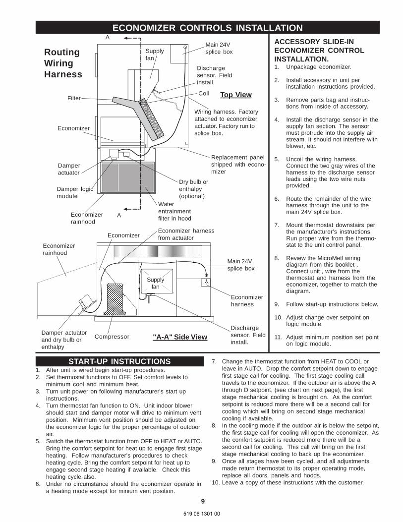
ECONOMIZER CONTROLS INSTALLATIONACCESSORY SLIDE-INECONOMIZER CONTROLINSTALLATION.1. Unpackage economizer.
2. Install accessory in unit perinstallation instructions provided.
3. Remove parts bag and instruc-tions from inside of accessory.
4. Install the discharge sensor in thesupply fan section. The sensormust protrude into the supply airstream. It should not interfere withblower, etc.
5. Uncoil the wiring harness.Connect the two gray wires of theharness to the discharge sensorleads using the two wire nutsprovided.
6. Route the remainder of the wireharness through the unit to themain 24V splice box.
7. Mount thermostat downstairs perthe manufacturer’s instructions.Run proper wire from the thermo-stat to the unit control panel.
8. Review the MicroMetl wiringdiagram from this booklet .Connect unit , wire from thethermostat and harness from theeconomizer, together to match thediagram.
9. Follow start-up instructions below.
10. Adjust change over setpoint onlogic module.
11. Adjust minimum position set pointon logic module.
START-UP INSTRUCTIONS1. After unit is wired begin start-up procedures.2. Set thermostat functions to OFF. Set comfort levels to
minimum cool and minimum heat.3. Turn unit power on following manufacturer's start up
instructions.4. Turn thermostat fan function to ON. Unit indoor blower
should start and damper motor will drive to minimum ventposition. Minimum vent position should be adjusted onthe economizer logic for the proper percentage of outdoorair.
5. Switch the thermostat function from OFF to HEAT or AUTO.Bring the comfort setpoint for heat up to engage first stageheating. Follow manufacturer’s procedures to checkheating cycle. Bring the comfort setpoint for heat up toengage second stage heating if available. Check thisheating cycle also.
6. Under no circumstance should the economizer operate ina heating mode except for minium vent position.
7. Change the thermostat function from HEAT to COOL orleave in AUTO. Drop the comfort setpoint down to engagefirst stage call for cooling. The first stage cooling calltravels to the economizer. If the outdoor air is above the Athrough D setpoint, (see chart on next page), the firststage mechanical cooling is brought on. As the comfortsetpoint is reduced more there will be a second call forcooling which will bring on second stage mechanicalcooling if available.
8. In the cooling mode if the outdoor air is below the setpoint,the first stage call for cooling will open the economizer. Asthe comfort setpoint is reduced more there will be asecond call for cooling. This call will bring on the firststage mechanical cooling to back up the economizer.
9. Once all stages have been cycled, and all adjustmentsmade return thermostat to its proper operating mode,replace all doors, panels and hoods.
10. Leave a copy of these instructions with the customer.
A
Economizerrainhood
Damper actuatorand dry bulb orenthalpy
Supplyfan
Dischargesensor. Fieldinstall.
Main 24Vsplice box
Economizerharness
Compressor "A-A" Side View
EconomizerEconomizer harnessfrom actuator
Waterentrainmentfilter in hood
Economizer
Main 24Vsplice boxSupply
fan
Damperactuator
Damper logicmodule
Dry bulb orenthalpy(optional)
Filter
Economizerrainhood
Wiring harness. Factoryattached to economizeractuator. Factory run tosplice box.
Replacement panelshipped with econo-mizer
Dischargesensor. Fieldinstall.
A
Top ViewCoil
RoutingWiringHarness
519 06 1301 00
10
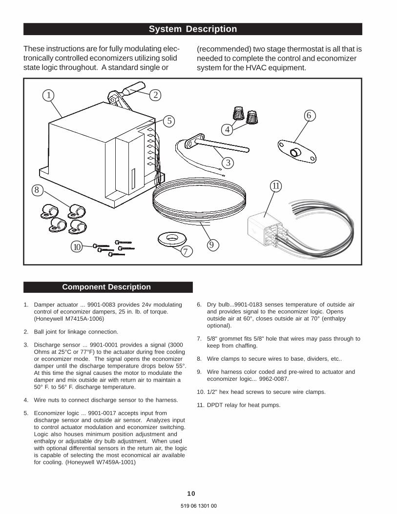
System Description
These instructions are for fully modulating elec-tronically controlled economizers utilizing solidstate logic throughout. A standard single or
(recommended) two stage thermostat is all that isneeded to complete the control and economizersystem for the HVAC equipment.
Component Description
1. Damper actuator ... 9901-0083 provides 24v modulatingcontrol of economizer dampers, 25 in. lb. of torque.(Honeywell M7415A-1006)
2. Ball joint for linkage connection.
3. Discharge sensor ... 9901-0001 provides a signal (3000Ohms at 25°C or 77°F) to the actuator during free coolingor economizer mode. The signal opens the economizerdamper until the discharge temperature drops below 55°.At this time the signal causes the motor to modulate thedamper and mix outside air with return air to maintain a50° F. to 56° F. discharge temperature.
4. Wire nuts to connect discharge sensor to the harness.
5. Economizer logic ... 9901-0017 accepts input fromdischarge sensor and outside air sensor. Analyzes inputto control actuator modulation and economizer switching.Logic also houses minimum position adjustment andenthalpy or adjustable dry bulb adjustment. When usedwith optional differential sensors in the return air, the logicis capable of selecting the most economical air availablefor cooling. (Honeywell W7459A-1001)
6. Dry bulb...9901-0183 senses temperature of outside airand provides signal to the economizer logic. Opensoutside air at 60°, closes outside air at 70° (enthalpyoptional).
7. 5/8" grommet fits 5/8" hole that wires may pass through tokeep from chaffing.
8. Wire clamps to secure wires to base, dividers, etc..
9. Wire harness color coded and pre-wired to actuator andeconomizer logic... 9962-0087.
10. 1/2" hex head screws to secure wire clamps.
11. DPDT relay for heat pumps.
1
465
3
8
9
2
710
11
519 06 1301 00

11
The purpose of an economizer is to use outdoor airfor cooling , whenever possible, to reduce compres-sor operation.
The economizer system initially responds to a signalfrom the cooling thermostat and functions as a truefirst stage for cooling, while providing maximum fueleconomy. The economizer is automatically lockedout during the heating mode and holds the outdoorair damper at the minimum position settings.
During the occupied period, on a call for cooling,when outdoor air temperature or enthalpy (optional)conditions are low, the economizer actuator willproportion to maintain between 50º F and 56º F atthermistor discharge sensor.
If the mixed or discharge temperature is above 56º F,actuator will open to admit additional outdoor air untilthe temperature returns to the 50º to 56º F range. Ifthe mixed or discharge air temperature is below 50ºF, the actuator will proportion closed, shutting theoutdoor air damper until the temperature returns tothe 50º to 56º F range. During the occupied period,the actuator will not close past the minimumposition.
INTEGRATED ECONOMIZERS
If the fully open actuator cannot satisfy the spacedemand, mechanical cooling is sequenced on.During the unoccupied period, the actuator willoverride minimum position setting and drive fullyclosed. On a loss of power, the actuator will springreturn fully closed.
When in heating operation, or when outdoor airtemperature or enthalpy (optional) conditions arehigh, economizer operation is locked out, andactuator is held at minimum position.
The staging relay is used when the first stagecompressors must provide mechanical coolingwhen assisting the economizer.
The staging relay can be omitted when the secondstage compressors can be used to assist theeconomizer with mechanical cooling.
519 06 1301 00
12
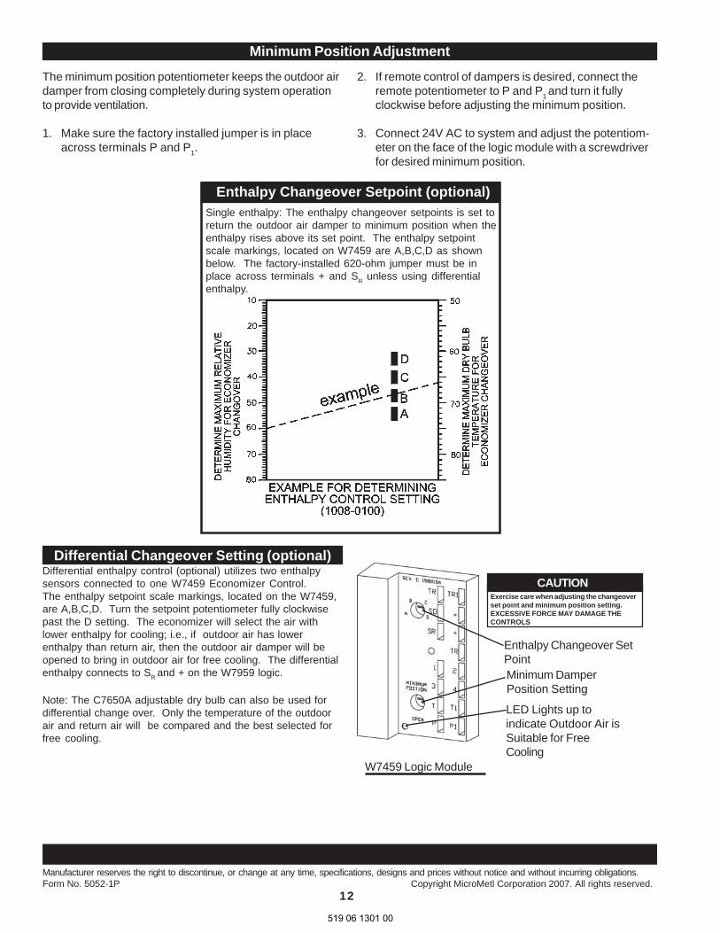
The minimum position potentiometer keeps the outdoor airdamper from closing completely during system operationto provide ventilation.
1. Make sure the factory installed jumper is in placeacross terminals P and P1.
Differential Changeover Setting (optional)Differential enthalpy control (optional) utilizes two enthalpysensors connected to one W7459 Economizer Control.The enthalpy setpoint scale markings, located on the W7459,are A,B,C,D. Turn the setpoint potentiometer fully clockwisepast the D setting. The economizer will select the air withlower enthalpy for cooling; i.e., if outdoor air has lowerenthalpy than return air, then the outdoor air damper will beopened to bring in outdoor air for free cooling. The differentialenthalpy connects to SR and + on the W7959 logic.
Note: The C7650A adjustable dry bulb can also be used fordifferential change over. Only the temperature of the outdoorair and return air will be compared and the best selected forfree cooling.
CAUTIONExercise care when adjusting the changeoverset point and minimum position setting.EXCESSIVE FORCE MAY DAMAGE THECONTROLS
Enthalpy Changeover SetPointMinimum DamperPosition Setting
LED Lights up toindicate Outdoor Air isSuitable for FreeCooling
W7459 Logic Module
Enthalpy Changeover Setpoint (optional)Single enthalpy: The enthalpy changeover setpoints is set toreturn the outdoor air damper to minimum position when theenthalpy rises above its set point. The enthalpy setpointscale markings, located on W7459 are A,B,C,D as shownbelow. The factory-installed 620-ohm jumper must be inplace across terminals + and SR unless using differentialenthalpy.
Manufacturer reserves the right to discontinue, or change at any time, specifications, designs and prices without notice and without incurring obligations.Form No. 5052-1P Copyright MicroMetl Corporation 2007. All rights reserved.
Minimum Position Adjustment
2. If remote control of dampers is desired, connect theremote potentiometer to P and P1 and turn it fullyclockwise before adjusting the minimum position.
3. Connect 24V AC to system and adjust the potentiom-eter on the face of the logic module with a screwdriverfor desired minimum position.
519 06 1301 00
Recommended


