i
DESIGNING AND FABRICATING THE PUNCH CHUCK AND PRECISION HOLE
PUNCH DIAMETER 3.0MM, 3.5MM AND 4.0MM FOR TURRET PUNCH
MACHINE
PRABAGAR A/L MURUKESAVAN
A report submitted in fulfillment of the
requirement for the award of the
Diploma of Mechanical Engineering
Faculty of Mechanical Engineering
University Malaysia Pahang
NOVEMBER 2008
ii
I hereby declare that I have read this project report
and in my opinion this project report is sufficient in
terms of scope and quality for the award of the
Diploma in Mechanical Engineering
Signature : …………………………
Name of Supervisor : Mr.Hazami Bin Che Hussain
Date : November 2008
iii
I declare that this report entitled “Designing and Fabricating The Punch
Chuck And Precision Hole Punch Diameter 3.0mm, 3.5mm And 4.0mm For
Turret Punch Machine” is the result of my own research except as cited in the
references. The r ep o r t has not been accepted for any degree and is not
concurrently submitted in candidature of any other degree.
Signature : ………………………………..
Name : Prabagar a/l Murukesavan
Date : November 2008

iv
DEDICATION
This report is dedicated to God whose guidance, help and grace was instrumental in
making this humble work a reality. To my beloved father and mother,
Mr.Murukesavan Thannimalai and Mrs.Bathmavathi Rengasamy and my respected
supervisor, Mr.Hazami Bin Che Hussain..
v
ACKNOWLEDGEMENTS
First of all, the deepest sense of gratitude to the God, who guide and gave
me the strength and ability to complete this final year project. Infinite thanks I brace
upon Him.
I would like to take this opportunity to express my gratitude and sincere
appreciation to all those who gave me the possibility to complete this report. I am very
grateful to my supervisor Mr.Hazami Bin Che Hussain for his patience, trust and
supporting for guide me finished this project. I also sincerely thanks for the time spent
proofreading and correcting my many mistakes.
I would like to acknowledge to all the staffs in Mechanical Laboratory, whom
gave me permission to use the necessary tools in the laboratory and guide me the
machine’s operating system.
I would also like to express my deepest appreciation to my parents whom always
support me and motivate me to complete this final year project.
My sincere appreciation also extends to all my colleagues, housemates, and
friends whom had provided assistance at various occasions by support and ideas for this
final year project.
Finally to individuals who has involved neither directly nor indirectly in
succession of this thesis. Indeed I could never adequately express my indebtedness to all
of them. Hope all of them stay continue support me and give confidence in my efforts in
future. Thank you.

vi
ABSTRACT
Design and fabricating the punch chuck and precision hole punch 3.0mm, 3.5mm
and 4.0mm is a conceptual understanding of manufacturing engineering which is not
provided in daily lectures room due to the fact that it is advance knowledge in this field.
The project is to test and analyze the percentage of failure of punch tool fabricated using
mild steel during punching process. As such, it is vital to attain this basic knowledge
through this project. The purpose of this project is to design and fabricate the punch
chuck and precision hole punch 3.0mm, 3.5mm and 4.0mm. The design must follow the
dimensions of the original punch tool so that it could be mounted into the machine. A
material test should be done to determine the hardness of mild steel before fabrication.
The progress of this project needs documenting, as it can be a good reference for the
next student who involve in this project as well as for a research related to the punch
tool. This report describes the project development of the first prototype of punch chuck
and precision hole punch fabricated using mild steel material.

vii
ABSTRAK
Tujuan utama projek ini adalah untuk mereka dan membuat sebuah
pemegang penebuk dan penebuk bersaiz 3mm, 3.5mm dan 4mm. Konsep projek ini
adalah amat sukar difahami, dan jarang diberi perhatian ketika dalam kuliah maka projek
ini member ilmu yang lebih mendalam tentang projek ini. Projek ini adalah untuk
menguji dan menganalisa keupayaan penebuk yang diperbuat daripada besi tuang
semasa proses menebuk.Spesifikasi penebuk hendaklah mengikut spesifikasi asal supaya
boleh dimuatkan ke dalam mesin. Jenis bahan yang digunakan sebelum proses fabrikasi
haruslah diuji kekerasannya. Projek ini memerlukan dokumentasi yang baik kerana ia
boleh menjadi panduan kepada pelajar-pelajar selepas ini dan juga kajian berkaitan
dengan tajuk ini. Laporan ini menunjukkan projek pertama UMP berkaitan dengan
pemegang penebuk dan penebuk bersaiz 3mm, 3.5mm dan 4mm yang diperbuat
daripada besi tuang.
viii
TABLE OF CONTENTS
Page
SUPERVISOR’S DECLARATION ii
STUDENT’S DECLARATION iii
DEDICATION iv
ACKNOWLEDGEMENTS v
ABSTRACT vi
ABSTRAK vii
TABLE OF CONTENTS viii-x
LIST OF TABLES xi
LIST OF FIGURES xii-xiii
LIST OF SYMBOLS xiv
LIST OF APPENDICES xv
CHAPTER 1 INTRODUCTION 1
1.1 Project Synopsis 1
1.2 Problem Statement 2
1.3 Scope of Work 2
1.4 Objective of Project 3
1.5 Project Planning 4
1.6 Gantt Chart 6
CHAPTER 2 LITERATURE REVIEW 7
2.0 Introduction 7
2.1 Terminology 8
2.1.1 Turret Punch Machine 8
2.1.2 Sheet Metal 9
2.1.3 Punching 9
ix
2.1.4 Mild Steel 10
2.1.5 Tools
2.1.5.1. Punch Chuck 10
2.1.5.2. Precision Hole Punch 11
2.1.5.3. Machine Cartridge 12
2.2 Material Testing 13-14
CHAPTER 3 PROJECT METHODOLOGY
AND PROCEDURE 15
3.0 Introduction 15
3.1 Process Flow Chart 16-17
3.2 Designing 18
3.2.1 Proposed Design 18-19
3.2.2 Design Analysis 20
3.2.3 Finalized Design 21
3.2.4 Three Dimensional Drawing 22
3.2.4.1 Part Drawings 22-24
3.2.4.2 Assembly Drawings 25
3.3 Material Selection 26
3.4 Fabrication 27
3.4.1 Fabrication and Machining Concept 27
3.4.2 Fabrication of Punch Chuck 27
3.4.2.1 Gathering Information 27
3.4.2.2 Raw Materials 27
3.4.2.3 Turning Process Using
Lathe Machine 28-31
3.4.3 Fabrication of Punch Tool 32
3.4.3.1 Gathering Information 32
3.4.3.2 Raw Materials 32
3.4.3.3 Turning Process Using
Lathe Machine 32-34
x
3.5 Surface Finishing 35
CHAPTER 4 RESULTS AND DISCUSSION 36
4.1 Introduction 36
4.2 Final Product 37
4.3 Assembly 38
4.4 Testing Procedure 39
4.5 Result 40
4.5.1 Testing Outcomes 40
4.6 Discussion 41
CHAPTER 5 CONCLUSION 42
5.1 Conclusion 42
5.2 Recommendation 43
REFERENCES 44
APPENDICES 45-47
xi
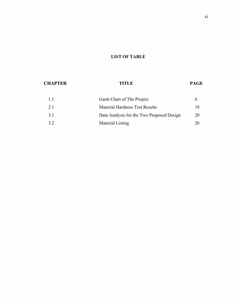
LIST OF TABLE
CHAPTER TITLE PAGE
1.1 Gantt Chart of The Project 6
2.1 Material Hardness Test Results 18
3.1 Data Analysis for the Two Proposed Design 20
3.2 Material Listing 26
xii
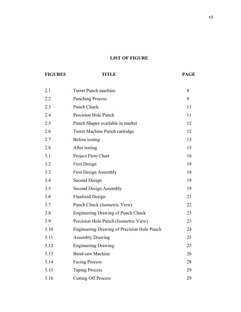
LIST OF FIGURE
FIGURES TITLE PAGE
2.1 Turret Punch machine 8
2.2 Punching Process 9
2.3 Punch Chuck 11
2.4 Precision Hole Punch 11
2.5 Punch Shapes available in market 12
2.6 Turret Machine Punch cartridge 12
2.7 Before testing 13
2.8 After testing 13
3.1 Project Flow Chart 16
3.2 First Design 18
3.3 First Design Assembly 18
3.4 Second Design 19
3.5 Second Design Assembly 19
3.6 Finalized Design 21
3.7 Punch Chuck (Isometric View) 22
3.8 Engineering Drawing of Punch Chuck 23
3.9 Precision Hole Punch (Isometric View) 23
3.10 Engineering Drawing of Precision Hole Punch 24
3.11 Assembly Drawing 25
3.12 Engineering Drawing 25
3.13 Bend-saw Machine 26
3.14 Facing Process 28
3.15 Taping Process 29
3.16 Cutting Off Process 29

xiii
3.17 Drilling Process 30
3.18 Threading process 31
3.19 Facing Process 33
3.20 Threading Process 34
3.21 Filing Process 34
3.22 Surface Finishing 35
4.1 Punch Chuck 37
4.2 Precision Hole Punch Diameter 3mm, 3.5mm and 4mm 37
4.3 Assembly Process 38
4.4 Final Assembly 38
4.5 Punch tool inside the machine cartridge 39
4.6 Testing Process 40

xiv
LIST OF SYMBOLS
SYMBOL NAME
kN Kilo Newton
º Degree
in Inches
% Percentage
kg/m3 Kilogram per meter cube
lb/in3 Pound per inches cube
MPa Mega Pascal
Gpa Giga Pascal
psi Pound per square inch
mm Millimeter
Ø Diameter
rpm Revolution per Minute
xv
LIST OF APPENDICES
CHAPTER TITLE PAGE
APPENDIX A - FABRICATION PART .....................................................................45
APPENDIX B - TOOLS AND MACHINE USED………………………………46-47
1
CHAPTER 1
INTRODUCTION
As a mechanical engineering student of University Malaysia Pahang (UMP), the
final year project gives student a chance to practice all the knowledge and skills that
they gain along the academic session in solving problems through a project in order to
be an efficient and a good engineer.
1.1. Project Synopsis
This project involves designing and fabricating a punch chuck and precision hole
punch. As the Diploma final year project allocates the duration of one semester, this
project requires significant number of machining processes such as facing, turning and
surface finishing. Basically the main processes that are involved in this project is the
fabrication of the turret machine punch chuck and precision hole punch using a lathe
machine combining different kinds of cutting process. This project is designed to be
compatible with the Trumpf CNC Turret Machine.

2
1.2. Problem Statement
The CNC Turret Machine is a machine used to process sheet metals using
different types of punch tools. The punch chuck and tools are specially made and
imported from Trumpf Manufacturers from Germany. Because of frequent use and low
maintenance of the punch chuck and tools, the products tend to fail after a certain period
of time. After this happens, it takes an amount of time to get approval from higher
authorities to purchase a new tool and delay from the suppliers.
This project is purposed to find an alternative tool which is easy to fabricate and
using materials which are easily found.
1.3. Scope of Work
In order to finish this project, it requires precise scope of work and proper plan
need to be followed because this project must go through various processes before it can
be produced. Beside that this project title is a new idea which is from an instructor
engineer in lab and as the knowledge isn’t entirely covered in classes or lab. So it give
us advantages to learn new process to produce this product and absolutely we could find
lot of advantages neither we are realized or not. These are scope of work in this project,
These scopes help me to be focused and know about my job. The scopes are:
a) Literature review on punch chuck and precision hole punch
b) Design a punch chuck and precision hole punch using Computer Aided
Design (SolidWorks)
c) Test the hardness of mild steel using Rockwell hardness test.
d) Fabricate the punch chuck and precision hole punch from mild steel material
using Conventional Lathe Machine.
e) Fit and test run the fabricated tool at the CNC Turret Punch Machine.
3
The punch tool can be used to punch aluminium sheet metals for thickness less
than 1mm.It is time where the soft skill e.g. punctuality, self discipline, time
management and problem solving have been practiced because the project highly
depend on the effectiveness of all the skill as much as the knowledge we have learnt.
1.4. Objective of Project
i) The main objective of Designing and Fabricating The Punch Chuck And
Precision Hole Punch Diameter 3.0mm, 3.5mm And 4.0mm For Turret
Punch Machine is to fabricate the alternative Punch Chuck and Precision
Hole Punch using mild steel material.
ii) The other objectives of this project is to analyze whether the mild steel
material made tool can withstand the turret machine punch force and to
determine the percentage of failure using the mild steel made tool on
sheet metals such as aluminium of thickness less than 1mm..

4
1.5. Project Planning
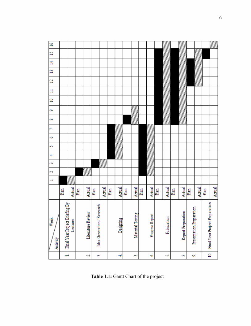
Based on the Gantt chart in Table 1.1, the confirmation of project title was done
on Week 1.This project begun with a research and literature review made via internet,
catalogs, supervisor, and others relevant academic material that related to the title, this
literature review was done on week 2. This continues along the way of this project
because there is a lot of knowledge to be learned.
At the same week, some schedule management for this project which included
schedule management for the project. This is done by using Microsoft Excel Project
using Gantt chart system.
Supervisor gave briefing about the introduction of the project and the usage of
the punch chuck and precision hole punch.
The sketching of the model takes about 1 week to be done and done on week 4.
The sketching done using manual sketched at A4 size paper and the engineering drawing
is done using Solid Work software. This was done from week 5 to week 7. The design of
the sketching are deeply discussed and the best design that suits is selected. The design
also must be suitable for the Trumpf CNC Turret Machine.
The next task is preparation of progress presentation of the project. In this
particular week, the student receives aids from the supervisor about the presentation.
The preparation of the presentation requires comments and correction from the
supervisor.
On week 8, which is the material testing week where different types of materials
are tested for their hardness properties using Rockwell Hardness Tester and the hardness
are compared. Then, the material suitable for punching thin sheet metals is chosen.
5
Next is the fabrication process. The punch chuck and precision hole punch is
fabricated using Conventional Lathe machine. The knowledge of manufacturing process
is applicable here. This task scheduled to take time about eight weeks and is done from
week 8 to week 15.
Finally, the surface finishing process using sandpaper is done. To achieve and
analyze the percentage of failure of this tool, it is tested on the Trumpf CNC Turret
Machine.
Next task is the final report writing and final presentation preparation. This take
about one week to accomplished which is week 16. The report is done with the
supervisor’s guidance. All the task is scheduled to take about sixteen weeks overall.
6
Table 1.1: Gantt Chart of the project
7
CHAPTER 2
LITERATURE REVIEW
The title design and fabrication of a Punch chuck and Precision Hole Punch
requires an amount of good understanding on the knowledge of the CNC Turret Punch
Machine. Therefore, executing a research is necessary to obtain all the information
available and related to this topic. The information or literature reviews obtained are
essentially valuable to assist in the fabrication and specification of this final year project.
With this grounds established, the project can proceed with guidance and assertiveness
in achieving the target mark.
2.0. Introduction
The machine used in FKM lab is the Trumatic 2020R FMC model from Trumpf
Company. Trumatic 2020R FMC is a high-precision coordinate-holing sheet-processing
center with numerical program control. It has: high speed of cutting-out and a hydraulic
cutting head with 360° rotation as well as an easy-to-use linear tool buffer. A
professional in the field of cutting produces parts without scratches and with high
accuracy and uniformity. It is manufactured in the year 2005 in Germany. The
maximum punch capacity of this machine is 180kN. The tools associated with this
machine are usually made from High Speed Steel (HSS) material and from Trumpf
Company.
8
2.1. Terminology
2.1.1. Turret Punch Machine
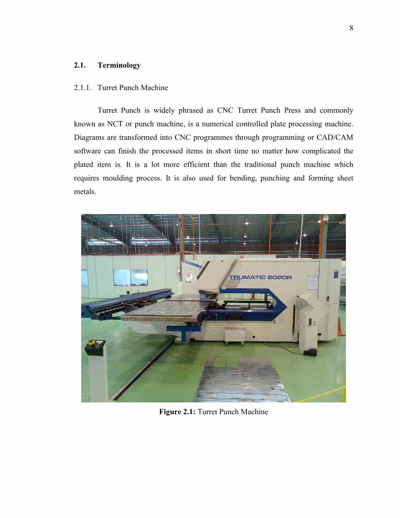
Turret Punch is widely phrased as CNC Turret Punch Press and commonly
known as NCT or punch machine, is a numerical controlled plate processing machine.
Diagrams are transformed into CNC programmes through programming or CAD/CAM
software can finish the processed items in short time no matter how complicated the
plated item is. It is a lot more efficient than the traditional punch machine which
requires moulding process. It is also used for bending, punching and forming sheet
metals.
Figure 2.1: Turret Punch Machine

9
2.1.2. Sheet Metal
Sheet metal is simply metal formed into thin and flat pieces. It is one of the
fundamental forms used in metalworking, and can be cut and bent into a variety of
different shapes. Countless everyday objects are constructed of the material.
Thicknesses can vary significantly, although extremely thin thicknesses are considered
foil or leaf, and pieces thicker than 6mm (0.25in) are considered plate.
Sheet metal is available as flat pieces or as a coiled strip. The coils are formed by
running a continuous sheet of metal through a roll slitter. The thickness of the sheet
metal is called its gauge. The gauge of sheet metal ranges from 30 gauge to about 8
gauge. The higher the gauge, the thinner the metal is.
2.1.3. Punching
Punching is performed by moving the sheet metal between the top and bottom
tools of a punch. The top tool (punch) mates with the bottom tool (die), cutting a simple
shape (e.g. a square, circle, or hexagon) from the sheet. An area can be cut out by
making several hundred small square cuts around the perimeter. A punch is less flexible
than a laser for cutting compound shapes, but faster for repetitive shapes. A typical CNC
punch has a choice of up to 60 tools in a ‘turret’ that can be rotated to bring any tool to
the active punching position. A modern CNC punch can take 600 blows per minute.
Figure 2.2: Punching Process
Recommended