
Dell™ Latitude™ 13 Service Manual
Notes, Cautions, and Warnings
If you purchased a Dell™ n Series computer, any references in this document to Microsoft® Windows® operating systems are not applicable.
Information in this document is subject to change without notice. © 2010 Dell Inc. All rights reserved.
Reproduction of this material in any manner whatsoever without the written permission of Dell Inc. is strictly forbidden.
Other trademarks and trade names may be used in this document to refer to either the entities claiming the marks and names or their products. Dell Inc. disclaims any proprietary interest in trademarks and trade names other than its own.
March 2010 Rev. A00
Working on Your Computer
Removing and Replacing Parts
Specifications
System Setup
Diagnostics
NOTE: A NOTE indicates important information that helps you make better use of your computer.
CAUTION: A CAUTION indicates potential damage to hardware or loss of data if instructions are not followed.
WARNING: A WARNING indicates a potential for property damage, personal injury, or death.
Trademarks used in this text: Dell, the DELL logo, and Latitude are trademarks of Dell Inc.; Intel, Core, and Celeron are either trademarks or registered trademarks of Intel Corporation; Microsoft, Windows, Windows Vista, and the Windows Vista start button are either trademarks or registered trademarks of Microsoft Corporation in the United States and/or other countries; Bluetooth is a registered trademark of Bluetooth SIG, Inc.
Back to Contents Page
System Setup Dell™ Latitude™ 13 Service Manual
Entering System Setup
Boot Menu
Navigation Keystrokes
System Setup Menu Options
Your computer offers the following BIOS and System Setup options:
l Access System Setup by pressing <F2> l Bring up a one-time boot menu by pressing <F12> l Access the Intel® AMT settings by pressing <Ctrl> + <P>
Entering System Setup
Press <F2> to enter System Setup and make changes to user-definable settings. If you have trouble entering System Setup using this key, press <F2> when the keyboard lights first flash.
Boot Menu
Press <F12> when the Dell logo appears to initiate a one-time boot menu with a list of the valid boot devices for the computer. Diagnostics and Enter Setup options are also included in this menu. The devices listed on the boot menu depend on the bootable devices installed in the computer. This menu is useful when you are attempting to boot to a particular device or to bring up the diagnostics for the computer. Using the boot menu does not make any changes to the boot order stored in the BIOS.
Navigation Keystrokes
Use the following keystrokes to navigate System Setup screens.
System Setup Menu Options
The following tables describe the menu options for the System Setup program.
Navigation
Action Keystroke(s)
Expand and collapse field <Enter>, left- or right-arrow key, or +/–
Expand or collapse all fields < >
Exit BIOS <Esc>—Remain in Setup, Save/Exit, Discard/Exit
Change a setting Left or right-arrow key
Select field to change <Enter>
Cancel modification <Esc>
Reset defaults <Alt><F> or Load Defaults menu option
General
Option Description
System Information
This section lists the primary hardware features of your computer. There are no configurable options in this section.
l System Information ¡ BIOS Version ¡ Service Tag ¡ Asset Tag ¡ Ownership Tag
l Memory Information ¡ Memory Installed ¡ Memory Available ¡ Memory Speed ¡ Memory Channel Mode ¡ Memory Technology ¡ DIMM A Size ¡ DIMM B Size
l Processor Information ¡ Processor Type ¡ Core Count ¡ Processor ID ¡ Current Clock Speed ¡ Minimum Clock Speed ¡ Maximum Clock Speed
l Device Information ¡ Primary Hard Drive ¡ System eSATA Device
¡ Video Controller ¡ Video BIOS Version ¡ Video Memory
¡ Panel Type ¡ Native Resolution
¡ Audio Controller ¡ Wi-Fi Device ¡ Cellular Device ¡ Bluetooth Device ¡ Integrated NIC MAC
Battery Information Displays the status of the battery and the type of AC adapter connected to the computer.
Boot Sequence
Specifies the order in which the computer attempts to find an operating system.
l Diskette drive l USB Storage Device l CD/DVD/CD-RW Drive l eSATA HDD l Onboard NIC
Date/Time Displays current date and time settings.
NOTE: System Configuration contains options and settings related to integrated system devices. Depending on your computer and installed devices, the items listed in this section may or may not appear.
System Configuration
Option Description
Integrated NICAllows you to configure the integrated network controller. The options are: Disabled, Enabled, Enabled w/PXE, and Enabled w/RPL
System Management Allows you to configure the system management options. The options are: Disabled, Alert Only, ASF 2.0, and DASH/ASF 2.0
SATA Operation Allows you to configure the operating mode of the internal SATA hard drive controller. The options are: Disabled, ATA, and AHCI
Miscellaneous Devices
Allows you to enable or disable the following devices:
l eSATA Ports l External USB Port l Microphone
Default setting: All enabled.
Video
Option Description
LCD Brightness Allows you to set the display brightness depending up on the power source (On Battery and On AC).
Security
Option Description
Admin Password
Allows you to set, change, or delete the administrator (admin) password. When set, the admin password enables several security features including:
l Restricts changes to the settings in Setup l Restricts the boot devices listed in the <F12> Boot Menu to those enabled in the "Boot Sequence" field l Prohibits changes to the owner and asset tags l Substitutes for the system and hard drive password
NOTE: You must set the admin password before you set the system or hard drive password. NOTE: Successful password changes take effect immediately. NOTE: Deleting the admin password automatically deletes the system password as well.
System Password
Allows you to set, change, or delete the system password. When set, your computer requests you to enter the system password every time your computer turns on or restarts.
NOTE: Successful password changes take effect immediately.
Internal HDD Password
This field lets you set, change, or delete the password on the system's internal hard disk drive (HDD). Successful changes take place immediately and require a system restart. The HDD password travels with the hard drive, so the HDD is protected even when installed in another system.
Password Bypass
Allows you to bypass the system and internal hard drive password prompts when your computer restarts or resumes from standby.
You can set Password Bypass to: Disabled, Reboot Bypass, Resume Bypass, and Reboot & Resume Bypass.
NOTE: You cannot bypass the system or hard drive password when you turn on your computer that has been shut down.
Password Change Allows you to enable of disable changes to the System and hard drive passwords when the admin password is set.
TPM Security
Allows you to enable or disable the Trusted Platform Module (TPM) on the computer.
NOTE: Disabling this option does not change any settings you may have made to the TPM, or delete any information or keys you may have stored there.
When TPM is enabled, the following options are available:
l Deactivate—Disables the TPM. The TPM restricts access to the stored owner information and does not execute any commands that use TPM resources.
l Activate—Enables and activates the TPM. l Clear—Clears the owner information stored in the TPM.
Allows you to enable or disable the optional Computrace software. The options are Deactivate, Disable, and Activate.
Computrace® NOTE: The Activate and Disable options will permanently activate or disable the feature and no further changes will be allowed.
CPU XD Support
Allows you to enable or disable the Execute Disable mode of the processor.
Default setting: Enabled
Performance
Option Description
Multi Core Support Enables or disables multi-core support for the processor.
Intel® SpeedStep™ Enables or disables the Intel SpeedStep feature.
Power Management
Option Description
Wake on AC Allows you to enable or disable the computer from turning on automatically when an AC adapter is connected.
Auto On Time
Allows you to set the time at which the computer must turn on automatically.
You can set the of days, if any, when you would like the system to turn on automatically. The settings are Disabled, Everyday, or Weekdays.
Default setting: Off
USB Wake Support
Allows you to enable or disable the ability of USB devices to wake the computer from Standby.
This feature is only functional when the AC power adapter is connected. If the AC power adapter is removed during Standby, the BIOS will remove power from all of the USB ports to conserve battery power.
Wake on LAN/WLAN
Allows the computer to turn on by a special LAN signal or from Hibernate state when triggered by a special wireless LAN signal. Wake-up from the Standby state is unaffected by this setting and must be enabled in the operating system.
l Disabled — Do not allow the system to power on when it receives a wake-up signal from the LAN or wireless LAN. l LAN Only — Allow the system to be powered on by special LAN signals. l WLAN Only — Allow the system to be powered on by special WLAN signals. l LAN or WLAN — Allow the system to be powered on by special LAN or wireless LAN signals.
The factory default setting is Off.
ExpressChargeAllows you to enable or disable the ExpressCharge feature. NOTE: ExpressCharge may not be available for all battries.
Charger Behavior
Allows you to enable or disable the battery charger. If disabled, the battery will not lose power when the system is connected to an AC adapter but it will not charge either.
Default setting: Charger Enabled
POST Behavior
Option Description
Adapter Warnings
Allows you to enable or disable the BIOS warning messages when you use certain power adapters. The BIOS displays these messages if you attempt to use a power adapter that has too little capacity for your configuration.
The factory default setting is Enabled.
Keypad (Embedded)
Allows you to select one of two methods to enable the keypad that is embedded in the internal keyboard.
l Fn Key Only — The keypad is only enabled when you hold down the <Fn> key. l By Num Lk — The keypad is enabled when (1) the Num Lock LED is on and (2) no external keyboard is attached. Note that the
system might not notice immediately when an external keyboard is detached.
NOTE: When Setup is running, this field has no effect—Setup works in the Fn Key Only mode.
Default setting: Fn Key Only.
Numlock LED
Allows you to enable or disable the Num Lock LED when the computer boots.
Default setting: Enabled.
USB Emulation
Defines how the BIOS handles the USB devices. USB emulation is always enabled during POST.
The factory default setting is Enabled.
Fn Key Emulation
Allows you to use the <Scroll Lock> key on an external PS/2 keyboard the same way you use the <Fn> key on the computer's internal keyboard.
NOTE: USB keyboards cannot emulate the <Fn> key if you are running an ACPI operating system such as Microsoft® Windows® XP. USB keyboards will only emulate the <Fn> key in non-ACPI mode (e.g., when you are running a DOS).
Default setting: Enabled.
Fast Boot
Allows you to enable or disable the Fast Boot feature. The following options are available:
l Minimal — Boot quickly unless the BIOS has been updated, memory changed, or the previous POST did not complete. l Thorough — Do not skip any steps in the boot process. l Auto — Allow the operating system to control this setting (this works only when the operating system supports Simple Boot Flag).
Default setting: Minimal
Intel Fast Call for Help
Used in conjunction with iAMT 4.0. Allows users to initiate contact with a management console while residing outside of the corporate infrastructure (i.e. remote location, behind a firewall or NAT, etc.) Use the check box to enable / disable this feature.

Back to Contents Page
Virtualization Support
Option Description
VT for Direct I/O
Specifies whether a Virtual Machine Monitor (VMM) can utilize the additional hardware capabilities provided by Intel Virtualization Technology for Direct I/O.
Default setting: Disabled.
Wireless
Option Description
Wireless Devices Allows you to enable or disable the following wireless devices: Internal WWAN, Internal WLAN, and Internal Bluetooth.
Maintenance
Option Description
Service Tag
Displays your computer's Service Tag. If for some reason the Service Tag was not already set, you would be able to use this field to set it.
If a Service Tag has not been set for this computer, the computer will automatically bring up this screen when you enter the BIOS. You will be prompted to enter the Service Tag.
Asset Tag Allows you to create a system Asset Tag. The field can only be updated if the Asset Tag is not already set.
System Logs
Option Description
BIOS Events Allows you to view and clear BIOS POST events. It includes the date and time of the event as well as the LED code.
DellDiag Events
Allows you to view the diagnostic results from Dell Diagnostics and PSA. It includes the time and date, the diagnostic and version which was run and the resulting code.
Thermal Events
Allows you to view and clear thermal events. It includes the date and time as well as the name of the event.
Power Events Allows you to view and clear power events. It includes the date and time of the event as well as the power state and reason.

Dell Training Tool | Latitude 13
Previous | Next
Drivers
Bios Options
Chassis View
Expand All Collapse All
Introduction
Welcome
Using This Material
Course Introduction
Product Overview
System Overview
Essential Knowledge
Software
Bios Simulation
Diagnostic Tools
Chassis
CRU Listing
Field Service Information
Safety Precautions
Service Issues
Interactive Teardown
Disassembly and Reassembly
Hard Drive Cable Kit
Express Card
SD Memory Card
Bottom Base Cover
Battery
SIM Card
SIM Board
WLAN
WWAN
Audio Board / Hard Drive
Hal Sensor Board
Speaker
LED Cover
Memory
Keyboard
Card Reader Board
Coin-Cell Battery
System Board
Heat Sink / CPU Fan
Bluetooth®
Palm Rest / LCD Assembly
LCD Bezel
LCD Panel
Camera
LCD Top Cover
Appendixes
Specifications
Online Review
Document History
Document Outline
Printer-Friendly Format
Hard Drive Cable Kit
CAUTION:
Please follow the Safety Precautions before removing any part from the system.
Installing The Hard Drive Cable Kit
1. Pre-Removal Instructions
Technicians need to remove the following components prior proceeding to installing the hard drive cable kit:
1. Remove the Express Card
2. Remove the SD Memory Card
3. Remove the Bottom Base Cover
4. Remove the Battery
2. Establishing image.
3. Disconnect both end of the existing hard drive flex cable from the system board and hard drive connectors.
4. The hard drive flex cable is attached with a double sided tape. Peel off the cable from the system.
5. Remove the cloth tape from the card reader board edge.
NOTE:
Skip this step if the cloth tape is not there.

Step 1: Arrange the cable in order to leave assembly space of new rubber.
Step 2: Peel off the double sided tape and attach the rubber bumper to the system.
Step 3: After adding the rubber bumper, re-assemble the cable.
NOTE:
The steps described below address HDD flex cable broken issue. This new solution will improve serviceability that will ease
DSP installation.
NOTE:
It is important that the onsite technician paste the rubber bumper to the right position as shown in this step in order to protect the
replacement cable from being cut by the card reader board edge.
NOTE:
Cable should be pressed back to the gap between board and HDD

Step 4: Fix the cable and rubber as indicated in the diagrams below.
NOTE:
The tape used here is for fixing black cable 100%.
Copyright 1999-2010 Dell Inc. For Dell Employees and Dell Service Providers only.
inside.us.dell.com | Privacy Policy | About Dell | Contact Us | About Us
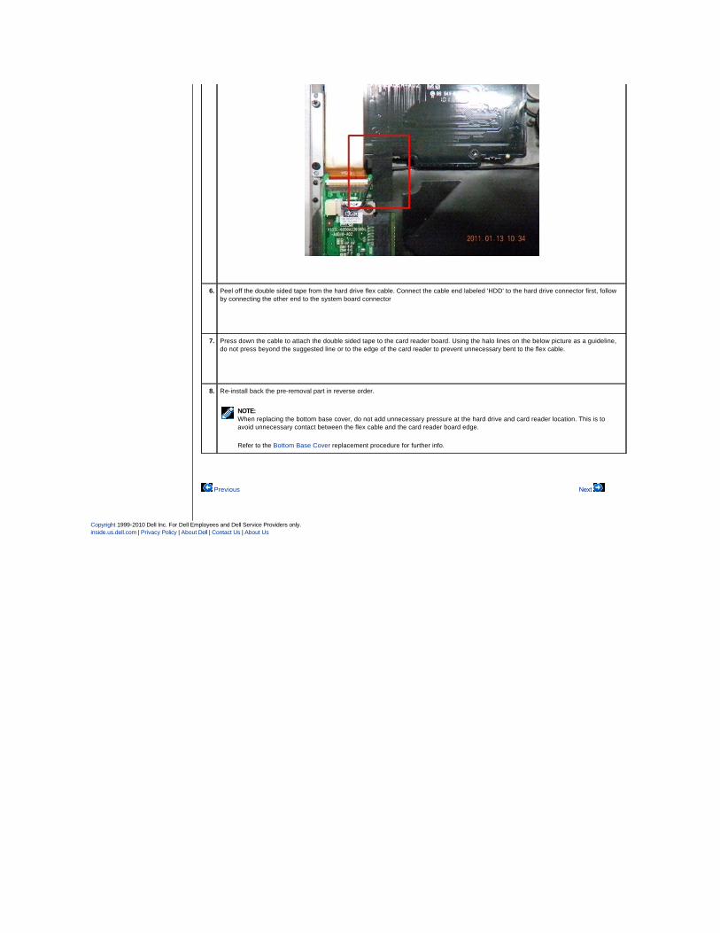
6. Peel off the double sided tape from the hard drive flex cable. Connect the cable end labeled 'HDD' to the hard drive connector first, follow
by connecting the other end to the system board connector
7. Press down the cable to attach the double sided tape to the card reader board. Using the halo lines on the below picture as a guideline,
do not press beyond the suggested line or to the edge of the card reader to prevent unnecessary bent to the flex cable.
8. Re-install back the pre-removal part in reverse order.
NOTE:
When replacing the bottom base cover, do not add unnecessary pressure at the hard drive and card reader location. This is to
avoid unnecessary contact between the flex cable and the card reader board edge.
Refer to the Bottom Base Cover replacement procedure for further info.
Previous
Next


Back to Contents Page
Diagnostics Dell™ Latitude™ 13 Service Manual
Device Status Lights
Battery Status Lights
Battery Charge and Health
Keyboard Status Lights
LED Error Codes
Device Status Lights
Battery Status Lights
If the computer is connected to an electrical outlet, the battery light operates as follows:
l Alternately blinking amber light and blue light — An unauthenticated or unsupported, non-Dell AC adapter is attached to your laptop. l Alternately blinking amber light with steady blue light — Temporary battery failure with AC adapter present. l Constantly blinking amber light — Fatal battery failure with AC adapter present. l Light off — Battery in full charge mode with AC adapter present. l Blue light on — Battery in charge mode with AC adapter present.
Battery Charge and Health
To check the battery charge, press and release the status button on the battery charge gauge to illuminate the charge-level lights. Each light represents approximately 20 percent of the total battery charge. For example, if four lights are on, the battery has 80 percent of its charge remaining. If no lights appear, the battery has no charge.
To check battery health using the charge gauge, press and hold the status button on the battery charge gauge for at least 3 seconds. If no lights appear, the battery is in good condition and more than 80 percent of its original charge capacity remains. Each light represents incremental degradation. If five lights appear, less than 60 percent of the charge capacity remains, and you should consider replacing the battery.
Keyboard Status Lights
The green lights located above the keyboard indicate the following:
LED Error Codes
The following table shows the possible LED codes that may display in a no-POST situation.
Turns on when you turn on the computer and blinks when the computer is in a power management mode.
Turns on when the computer reads or writes data.
Turns on steadily or blinks to indicate battery charge status.
Turns on when wireless networking is enabled.
Turns on when a card with Bluetooth® wireless technology is enabled. To turn off only the Bluetooth wireless technology function, right-click the icon in the system tray and select Disable Bluetooth Radio.
Turns on when the numeric keypad is enabled.
Turns on when the Caps Lock function is enabled.
Turns on when the Scroll Lock function is enabled.
Appearance Description Next Step
ON-FLASH-FLASH
No SODIMMs are installed
1. Install supported memory modules. 2. If memory is already present, reseat the module(s) one at
time in each slot. 3. Try known good memory from another computer or replace the
memory. 4. Replace the system board.
FLASH-ON-ON
System board error
1. Reseat the processor. 2. Replace the system board. 3. Replace the processor.

Back to Contents Page
FLASH-ON-FLASH
display panel error
1. Reseat the display cable. 2. Replace the display panel. 3. Replace the video card/system board.
OFF-FLASH-OFF
Memory compatibility error
1. Install compatible memory modules. 2. If two modules are installed remove one and test. Try the
other module in the same slot and test. Test the other slot with both modules.
3. Replace the memory. 4. Replace the system board.
ON-FLASH-ON
Memory is detected but has errors
1. Reseat the memory. 2. If two modules are installed remove one and test. Try the
other module in the same slot and test. Test the other slot with both modules.
3. Replace the memory. 4. Replace the system board.
OFF-FLASH-FLASH
Modem error
1. Reseat the modem. 2. Replace the modem. 3. Replace the system board.
FLASH-FLASH-FLASH
System board error1. Replace the system board.
FLASH-FLASH-OFF
Option ROM error
1. Reseat the device. 2. Replace the device. 3. Replace the system board.
OFF-ON-OFF
Storage device error
1. Reseat the hard drive and optical drive. 2. Test the computer with just the hard drive and just the optical
drive. 3. Replace the device that is causing the failure. 4. Replace the system board.
FLASH-FLASH-ON
Video card error1. Replace the system board.

Back to Contents Page
Removing and Replacing Parts Dell™ Latitude™ 13 Service Manual
Back to Contents Page
ExpressCard
Base Cover
Wireless Local Area Network (WLAN) Card
Hard Drive and Audio Board
Speaker
Memory
Subscriber Identity Module (SIM) Card
Coin-Cell Battery
Heat Sink and Fan Assembly
Display Panel
Palm Rest and Display Assembly
Secure Digital (SD) Card
Battery
Display Closure Sensor
LED Cover
Keyboard
ExpressCard/SD Card Reader
SIM Card Reader
System Board
Internal Card With Bluetooth® Wireless Technology
Display Bezel
Camera
Hard Drive Cable Kit

Back to Contents Page
Specifications Dell™ Latitude™ 13 Service Manual
System Information
Memory
Audio
ExpressCard
Display
Touchpad
AC Adapter
Environmental
Processor
Video
Communications
Ports and Connectors
Keyboard
Battery
Physical
NOTE: Offerings may vary by region. For more information regarding the configuration of your computer, click Start® Help and Support and select the
option to view information about your computer.
System Information
Chipset Mobile Intel® GS45 Express Chipset
DRAM bus width 64-bit buses
Processor address bus width 36 bits
Flash EPROM SPI 16 Mbits
Processor
Types Intel Celeron® Ultra Low Voltage (ULV) Intel Core™2 Solo ULV Intel Core2 Duo ULV
L2 cache Intel Celeron ULV – 1MB Intel Core2 Solo ULV – 3 MB Intel Core2 Duo ULV – 3 MB
External bus frequency 800 MHz
Memory
Type DDR3
Speed supported: 1067 MHz functional: 800 MHz due to limitations of the front side bus (FSB)
Connector one SODIMM socket
Module capacities 1 GB, 2 GB, or 4 GB
Minimum memory 1 GB
Maximum memory 4 GB
Video
Type integrated on system board
Controller Intel GMA 4500MHD
Output 15-pin VGA connector
Audio
Type two-channel high definition audio
Controller Realtek ALC269
Stereo conversion 24-bit (analog-to-digital and digital-to-analog)
Interface:
Internal high definition audio
External microphone connector stereo headphones/external speakers connector
Speakers one 1.5 W
Internal speaker amplifier 1.5 W
Volume controls keyboard function keys (Fn+F3/F4/F5) and program menus
Communications
Network adapter 10/100/1000 Mbps Broadcom NetXtreme Ethernet LAN
Wireless dedicated WLAN, WWAN, and Bluetooth® wireless support if optional cards are purchased
ExpressCard

NOTE: The ExpressCard slot does not support PC Cards.
ExpressCard connector ExpressCard slot
Cards supported 34-mm ExpressCards
Ports and Connectors
Audio microphone connector stereo headphone/ speakers connector
Video 15-pin VGA connector
Network adapter RJ-45 connector
USB one 4-pin USB 2.0-compliant connector one eSATA/USB 2.0-compliant connector
Memory-card slot 5-in-1 memory-card slot supporting MS, MS Pro, SD, SDHC, and MMC cards
Mini Card PCI-E Half-Mini Card support for WLAN PCI-E Mini Card support for WWAN
Display
Type white light emitting diode (WLED) anti-glare LCD
Size 13.3-inch high definition (HD)
Active area (X/Y) 293.40 mm x 165.00 mm
Dimensions:
Height 188.80 mm (7.43 inches)
Width 314.10 mm (12.37 inches)
Diagonal 337.80 mm (13.30 inches)
Maximum resolution 1366 x 768 pixels at 262 K colors
Typical brightness 200 nits
Operating angle 0 degree (closed) to 135 degrees
Refresh rate 40 Hz and 60 Hz
Viewing angles:
Horizontal 40/40 degrees
Vertical 15/30 degrees
Pixel pitch 0.2148 mm
Keyboard
Number of keys United States and Canada: 83 keys International: 87 keys Japan: 90 keys
Layout QWERTY/AZERTY/Kanji
Touchpad
Active area:
X-axis 81.00 mm (3.19 inches)
Y-axis 42.00 mm (1.65 inches)
Battery
Type 6-cell "smart" lithium-ion (30 WHr)
Charge time with computer off approximately 4 hours (on a fully discharged battery)
Operating time battery operating time varies depending on operating conditions and can significantly reduce under certain power-intensive conditions
Life span approximately 300 charge/discharge cycles
Dimensions:
Depth 155.20 mm (6.11 inches)
Height 5.35 mm (0.21 inches)
Width 177.60 mm (6.99 inches)
Voltage 11.10 VDC
Temperature range:
Operating 0 °C to 35 °C (32 °F to 95 °F)
Storage –40 °C to 60 °C (–40 °F to 140 °F)
Coin-cell battery 3 V CR2025 lithium
AC Adapter

Back to Contents Page
Type
Input voltage 100–240 VAC
Input current (maximum) 1.5 A
Input frequency 50 Hz–60 Hz
Output current 4.34 A (maximum at 4-second pulse) 3.34 A (continuous)
Output voltage 19.5 +/– 1.0 VDC
Dimensions:
Height 16 mm (0.63 inches)
Width 66 mm (2.60 inches)
Depth 127 mm (5.00 inches)
Weight (approximate) 0.29 kg (0.64 lb)
Temperature range:
Operating 0° C to 40° C (32° F to 104° F)
Storage –40° C to 70° C (–40° F to 158° F)
Physical
Height (front to back) 16.50 mm – 19.70 mm (0.65 inch – 0.78 inch)
Width 330 mm (12.99 inches)
Depth 230 mm (9.05 inches)
Weight (approximate) 1.60 kg (3.53 lb)
Environmental
Temperature range:
Operating 0° C to 35° C (32° F to 95° F)
Storage –40° C to 65° C (–40° F to 149° F)
Relative humidity (maximum):
Operating 10% – 90% (noncondensing)
Storage 5% – 95% (noncondensing)
Maximum vibration:
Operating 0.66 Grms (2 Hz–600 Hz)
Non-operating 1.30 Grms (2 Hz–600 Hz)
NOTE: Vibration is measured using a random-vibration spectrum that simulates user environment.
Maximum shock:
Operating 142 G (2 ms)
Non-operating 162 G (2 ms)
NOTE: Shock is measured with hard drive in head-parked position and a 2-ms half-sine pulse.

Back to Contents Page
Hard Drive and Audio Board Dell™ Latitude™ 13 Service Manual
Removing the Hard Drive and Audio Board
1. Follow the procedures in Before Working Inside Your Computer. 2. Remove the ExpressCard, if applicable. 3. Remove the SD card, if applicable. 4. Remove the base cover. 5. Remove the battery. 6. Disconnect the speaker cable from the audio board.
7. Disconnect the hard-drive data cable from the audio board.
8. Remove the screws that secure the audio board and the hard drive to the computer.
9. Lift and remove the hard drive assembly and audio board from the computer.
10. Disengage the audio board from the hard drive.
11. Remove the screws that secure the hard-drive bracket to the hard drive.
12. Remove the hard drive from the hard-drive bracket.
Replacing the Hard Drive and Audio Board
To replace the hard drive and audio board, perform the above steps in reverse order.
Back to Contents Page
WARNING: Before working inside your computer, read the safety information that shipped with your computer. For additional safety best practices information, see the Regulatory Compliance Homepage at www.dell.com/regulatory_compliance.
NOTE: You may need to install Adobe® Flash® Player from Adobe.com in order to view the illustrations below.

Back to Contents Page
Battery Dell™ Latitude™ 13 Service Manual
Removing the Battery
1. Follow the procedures in Before Working Inside Your Computer. 2. Remove the ExpressCard, if applicable. 3. Remove the SD card, if applicable. 4. Remove the base cover. 5. Lift the black cable-release clip to release the battery cable from the connector on the system board and disconnect the battery cable.
6. Remove the screws that secure the battery to the computer.
7. Lift the battery up and away from the computer.
Replacing the Battery
To replace the battery, perform the above steps in reverse order.
Back to Contents Page
WARNING: Before working inside your computer, read the safety information that shipped with your computer. For additional safety best practices information, see the Regulatory Compliance Homepage at www.dell.com/regulatory_compliance.
NOTE: You may need to install Adobe® Flash® Player from Adobe.com in order to view the illustrations below.
Back to Contents Page
Internal Card With Bluetooth® Wireless Technology Dell™ Latitude™ 13 Service Manual
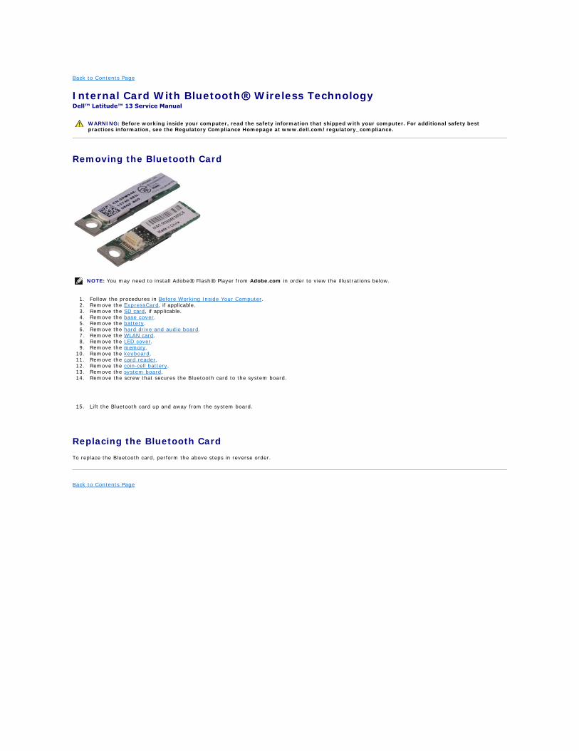
Removing the Bluetooth Card
1. Follow the procedures in Before Working Inside Your Computer. 2. Remove the ExpressCard, if applicable. 3. Remove the SD card, if applicable. 4. Remove the base cover. 5. Remove the battery. 6. Remove the hard drive and audio board. 7. Remove the WLAN card. 8. Remove the LED cover. 9. Remove the memory.
10. Remove the keyboard. 11. Remove the card reader. 12. Remove the coin-cell battery. 13. Remove the system board. 14. Remove the screw that secures the Bluetooth card to the system board.
15. Lift the Bluetooth card up and away from the system board.
Replacing the Bluetooth Card
To replace the Bluetooth card, perform the above steps in reverse order.
Back to Contents Page
WARNING: Before working inside your computer, read the safety information that shipped with your computer. For additional safety best practices information, see the Regulatory Compliance Homepage at www.dell.com/regulatory_compliance.
NOTE: You may need to install Adobe® Flash® Player from Adobe.com in order to view the illustrations below.
Back to Contents Page
Base Cover Dell™ Latitude™ 13 Service Manual
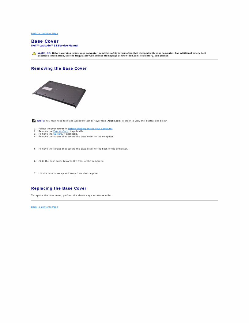
Removing the Base Cover
1. Follow the procedures in Before Working Inside Your Computer. 2. Remove the ExpressCard, if applicable. 3. Remove the SD card, if applicable. 4. Remove the screws that secure the base cover to the computer.
5. Remove the screws that secure the base cover to the back of the computer.
6. Slide the base cover towards the front of the computer.
7. Lift the base cover up and away from the computer.
Replacing the Base Cover
To replace the base cover, perform the above steps in reverse order.
Back to Contents Page
WARNING: Before working inside your computer, read the safety information that shipped with your computer. For additional safety best practices information, see the Regulatory Compliance Homepage at www.dell.com/regulatory_compliance.
NOTE: You may need to install Adobe® Flash® Player from Adobe.com in order to view the illustrations below.
Back to Contents Page
Camera Dell™ Latitude™ 13 Service Manual
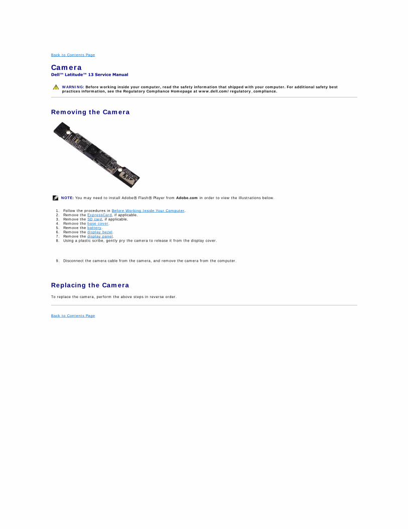
Removing the Camera
1. Follow the procedures in Before Working Inside Your Computer. 2. Remove the ExpressCard, if applicable. 3. Remove the SD card, if applicable. 4. Remove the base cover. 5. Remove the battery. 6. Remove the display bezel. 7. Remove the display panel. 8. Using a plastic scribe, gently pry the camera to release it from the display cover.
9. Disconnect the camera cable from the camera, and remove the camera from the computer.
Replacing the Camera
To replace the camera, perform the above steps in reverse order.
Back to Contents Page
WARNING: Before working inside your computer, read the safety information that shipped with your computer. For additional safety best practices information, see the Regulatory Compliance Homepage at www.dell.com/regulatory_compliance.
NOTE: You may need to install Adobe® Flash® Player from Adobe.com in order to view the illustrations below.
Back to Contents Page
ExpressCard/SD Card Reader Dell™ Latitude™ 13 Service Manual
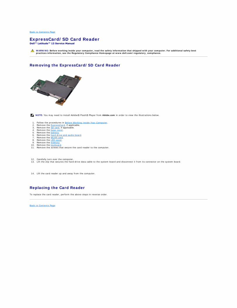
Removing the ExpressCard/SD Card Reader
1. Follow the procedures in Before Working Inside Your Computer. 2. Remove the ExpressCard, if applicable. 3. Remove the SD card, if applicable. 4. Remove the base cover. 5. Remove the battery. 6. Remove the hard drive and audio board. 7. Remove the WLAN card. 8. Remove the LED cover. 9. Remove the memory.
10. Remove the keyboard. 11. Remove the screws that secure the card reader to the computer.
12. Carefully turn over the computer. 13. Lift the clip that secures the hard-drive data cable to the system board and disconnect it from its connector on the system board.
14. Lift the card reader up and away from the computer.
Replacing the Card Reader
To replace the card reader, perform the above steps in reverse order.
Back to Contents Page
WARNING: Before working inside your computer, read the safety information that shipped with your computer. For additional safety best practices information, see the Regulatory Compliance Homepage at www.dell.com/regulatory_compliance.
NOTE: You may need to install Adobe® Flash® Player from Adobe.com in order to view the illustrations below.

Back to Contents Page
Coin-Cell Battery Dell™ Latitude™ 13 Service Manual
Removing the Coin-Cell Battery
1. Follow the procedures in Before Working Inside Your Computer. 2. Remove the ExpressCard, if applicable. 3. Remove the SD card, if applicable. 4. Remove the base cover. 5. Remove the battery. 6. Remove the hard drive and audio board. 7. Remove the LED cover. 8. Remove the keyboard. 9. Remove the card reader.
10. Remove the tape that secures the coin-cell battery cable to the computer.
11. Disconnect the coin-cell battery cable from the system board.
12. Remove the coin-cell battery and cable from the computer.
Replacing the Coin-Cell Battery
To replace the coin-cell battery, perform the above steps in reverse order.
Back to Contents Page
WARNING: Before working inside your computer, read the safety information that shipped with your computer. For additional safety best practices information, see the Regulatory Compliance Homepage at www.dell.com/regulatory_compliance.
NOTE: You may need to install Adobe® Flash® Player from Adobe.com in order to view the illustrations below.
Back to Contents Page
ExpressCard Dell™ Latitude™ 13 Service Manual
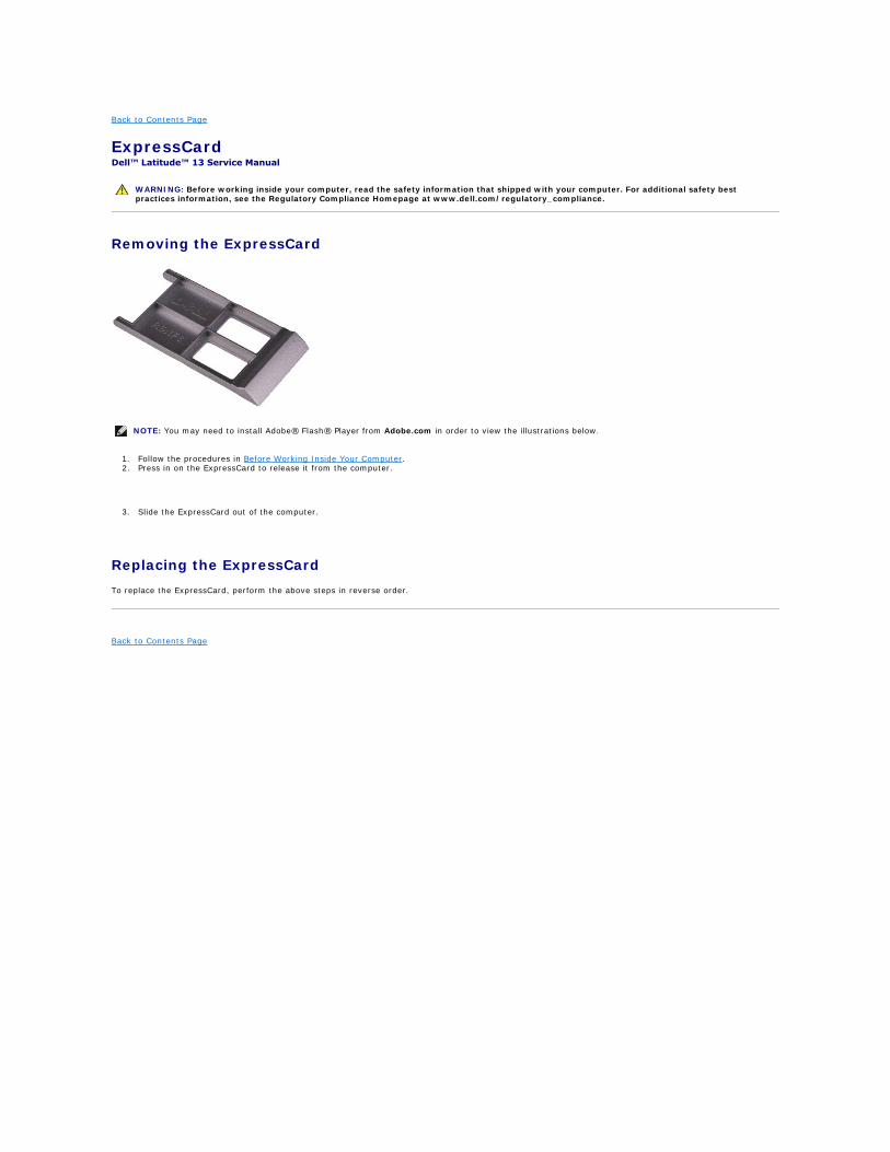
Removing the ExpressCard
1. Follow the procedures in Before Working Inside Your Computer. 2. Press in on the ExpressCard to release it from the computer.
3. Slide the ExpressCard out of the computer.
Replacing the ExpressCard
To replace the ExpressCard, perform the above steps in reverse order.
Back to Contents Page
WARNING: Before working inside your computer, read the safety information that shipped with your computer. For additional safety best practices information, see the Regulatory Compliance Homepage at www.dell.com/regulatory_compliance.
NOTE: You may need to install Adobe® Flash® Player from Adobe.com in order to view the illustrations below.
Back to Contents Page
Display Closure Sensor Dell™ Latitude™ 13 Service Manual
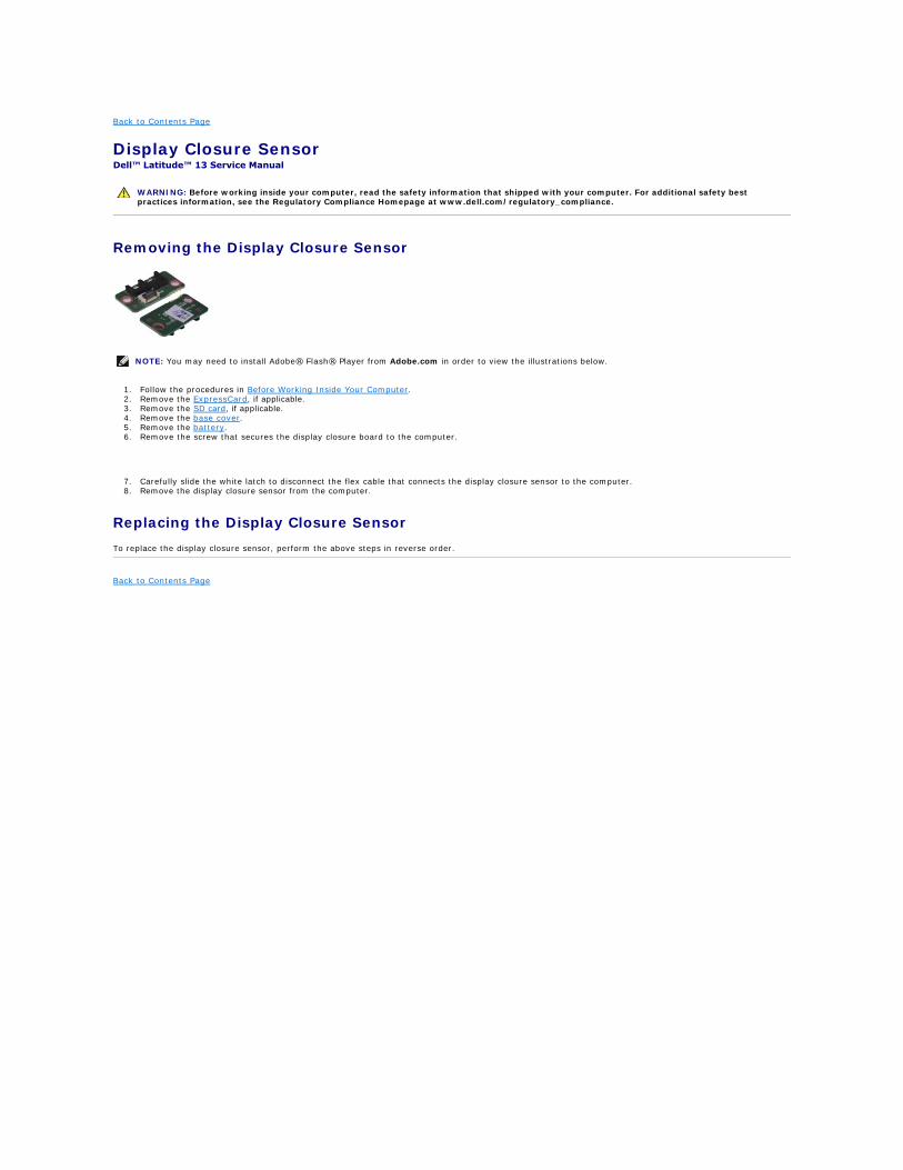
Removing the Display Closure Sensor
1. Follow the procedures in Before Working Inside Your Computer. 2. Remove the ExpressCard, if applicable. 3. Remove the SD card, if applicable. 4. Remove the base cover. 5. Remove the battery. 6. Remove the screw that secures the display closure board to the computer.
7. Carefully slide the white latch to disconnect the flex cable that connects the display closure sensor to the computer. 8. Remove the display closure sensor from the computer.
Replacing the Display Closure Sensor
To replace the display closure sensor, perform the above steps in reverse order.
Back to Contents Page
WARNING: Before working inside your computer, read the safety information that shipped with your computer. For additional safety best practices information, see the Regulatory Compliance Homepage at www.dell.com/regulatory_compliance.
NOTE: You may need to install Adobe® Flash® Player from Adobe.com in order to view the illustrations below.

Back to Contents Page
Hard Drive Cable Kit Dell™ Latitude™ 13 Service Manual
Installing the Hard Drive Cable Kit
1. Follow the procedures in Before Working Inside Your Computer. 2. Remove the ExpressCard, if applicable. 3. Remove the SD card, if applicable. 4. Remove the base cover. 5. Remove the battery.
6. Disconnect both ends of the existing hard drive flex cable from the system board and hard drive connectors.
WARNING: Before working inside your computer, read the safety information that shipped with your computer. For additional safety best practices information, see the Regulatory Compliance Homepage at www.dell.com/regulatory_compliance.
NOTE: You may need to install Adobe® Flash® Player from Adobe.com in order to view the illustrations below.

7. The hard drive flex cable is attached with a double sided tape. Peel off the cable from the system.
8. Remove the cloth tape from the card reader board edge.
NOTE: Skip this step if the cloth tape is not present.

Step 1: Arrange the cable in order to leave assembly space of new rubber.
Step 2: Peel off the double sided tape and attach the rubber bumper to the system.
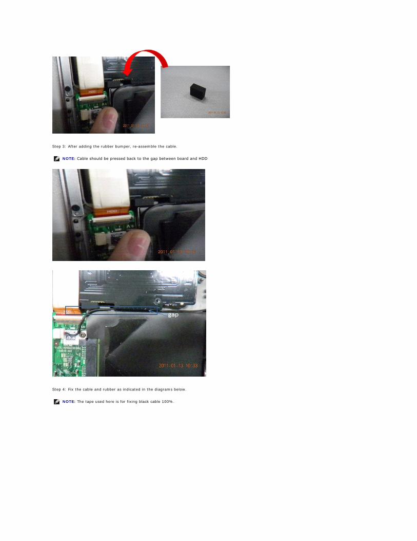
Step 3: After adding the rubber bumper, re-assemble the cable.
Step 4: Fix the cable and rubber as indicated in the diagrams below.
NOTE: Cable should be pressed back to the gap between board and HDD
NOTE: The tape used here is for fixing black cable 100%.

9. Peel off the double sided tape from the hard drive flex cable. Connect the cable end labeled 'HDD' to the hard drive connector first, follow by connecting the other end to the system board connector.
10. Press down the cable to attach the double sided tape to the card reader board. Using the halo lines on the below picture as a guideline, do not press beyond the suggested line or to the edge of the card reader to prevent unnecessary bent to the flex cable.

11. Re-install back the pre-removal part in reverse order.
Refer to the Bottom Base Cover replacement procedure for further information.
Back to Contents Page
NOTE: When replacing the bottom base cover, do not add unnecessary pressure at the hard drive and card reader location. This is to avoid unnecessary contact between the flex cable and the card reader board edge.

Back to Contents Page
Heat Sink and Fan Assembly Dell™ Latitude™ 13 Service Manual
Removing the Heat Sink and Fan Assembly
1. Follow the procedures in Before Working Inside Your Computer. 2. Remove the ExpressCard, if applicable. 3. Remove the SD card, if applicable. 4. Remove the base cover. 5. Remove the battery. 6. Remove the hard drive and audio board. 7. Remove the WLAN card. 8. Remove the LED cover. 9. Remove the memory.
10. Remove the keyboard. 11. Remove the card reader. 12. Remove the coin-cell battery. 13. Remove the system board. 14. Disconnect the fan cable from the system board.
15. Remove the screws that secure the heat sink and fan assembly to the system board.
16. Lift the heat sink and fan assembly up and away from the system board.
Replacing the Heat Sink and Fan Assembly
To replace the heat sink and fan assembly, perform the above steps in reverse order.
Back to Contents Page
WARNING: Before working inside your computer, read the safety information that shipped with your computer. For additional safety best practices information, see the Regulatory Compliance Homepage at www.dell.com/regulatory_compliance.
NOTE: You may need to install Adobe® Flash® Player from Adobe.com in order to view the illustrations below.

Back to Contents Page
Keyboard Dell™ Latitude™ 13 Service Manual
Removing the Keyboard
1. Follow the procedures in Before Working Inside Your Computer. 2. Remove the ExpressCard, if applicable. 3. Remove the SD card, if applicable. 4. Remove the base cover. 5. Remove the battery. 6. Remove the LED cover. 7. Remove the screws that secure keyboard to the computer.
8. Flip over the keyboard and lay it on the palm rest.
9. Carefully lift the white clip to release the keyboard cable.
10. Disconnect the keyboard cable from its connector on the system board.
11. Lift the keyboard up and away from the computer.
Replacing the Keyboard
To replace the keyboard, perform the above steps in reverse order.
Back to Contents Page
WARNING: Before working inside your computer, read the safety information that shipped with your computer. For additional safety best practices information, see the Regulatory Compliance Homepage at www.dell.com/regulatory_compliance.
NOTE: You may need to install Adobe® Flash® Player from Adobe.com in order to view the illustrations below.
Back to Contents Page
Display Panel Dell™ Latitude™ 13 Service Manual
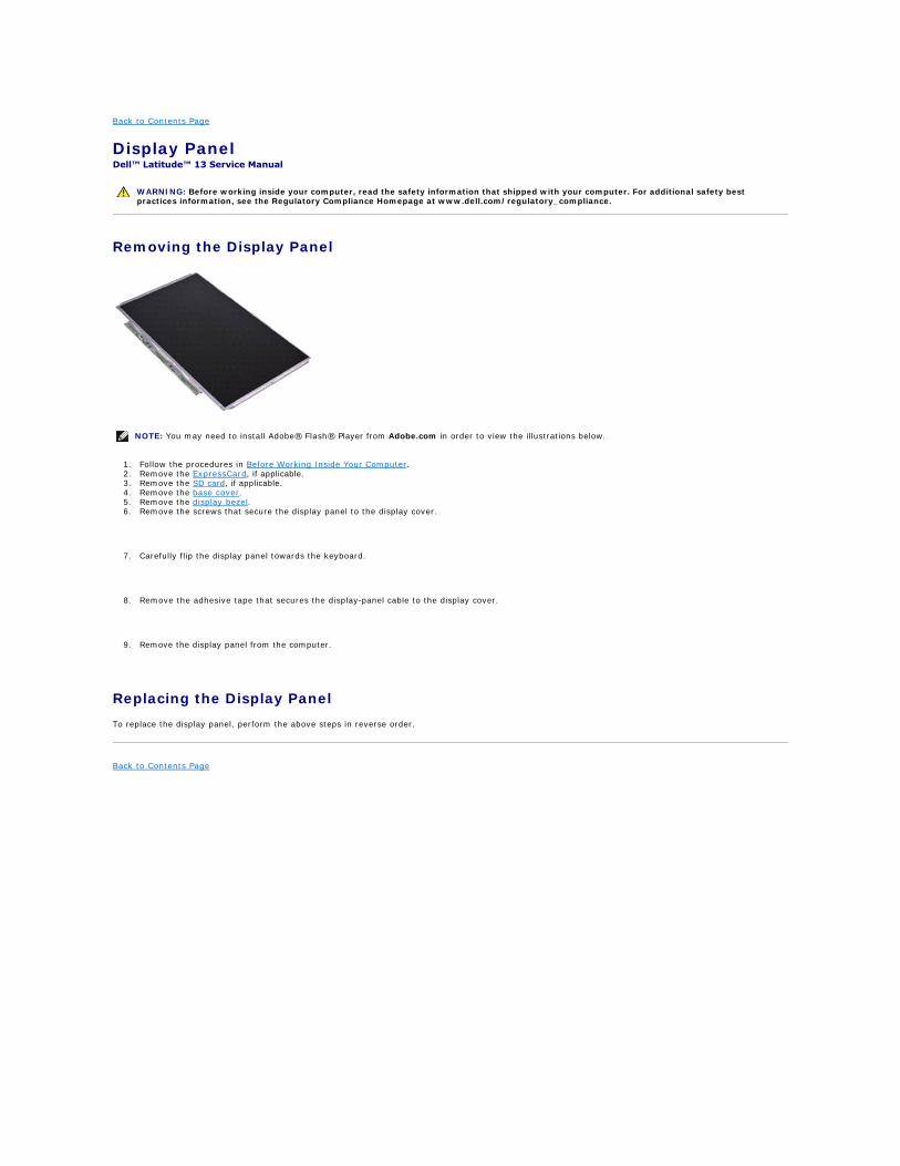
Removing the Display Panel
1. Follow the procedures in Before Working Inside Your Computer. 2. Remove the ExpressCard, if applicable. 3. Remove the SD card, if applicable. 4. Remove the base cover. 5. Remove the display bezel. 6. Remove the screws that secure the display panel to the display cover.
7. Carefully flip the display panel towards the keyboard.
8. Remove the adhesive tape that secures the display-panel cable to the display cover.
9. Remove the display panel from the computer.
Replacing the Display Panel
To replace the display panel, perform the above steps in reverse order.
Back to Contents Page
WARNING: Before working inside your computer, read the safety information that shipped with your computer. For additional safety best practices information, see the Regulatory Compliance Homepage at www.dell.com/regulatory_compliance.
NOTE: You may need to install Adobe® Flash® Player from Adobe.com in order to view the illustrations below.

Back to Contents Page
Display Bezel Dell™ Latitude™ 13 Service Manual
Removing the Display Bezel
1. Follow the procedures in Before Working Inside Your Computer. 2. Remove the screw covers from the display bezel.
3. Remove the screws that secure the display bezel to the display assembly.
4. Using a plastic scribe, gently pry under the display bezel to release it from the display assembly.
5. Lift the display bezel and remove it from the display assembly.
Replacing the Display Bezel
To replace the display bezel, perform the above steps in reverse order.
Back to Contents Page
WARNING: Before working inside your computer, read the safety information that shipped with your computer. For additional safety best practices information, see the Regulatory Compliance Homepage at www.dell.com/regulatory_compliance.
NOTE: You may need to install Adobe® Flash® Player from Adobe.com in order to view the illustrations below.
Back to Contents Page
Memory Dell™ Latitude™ 13 Service Manual
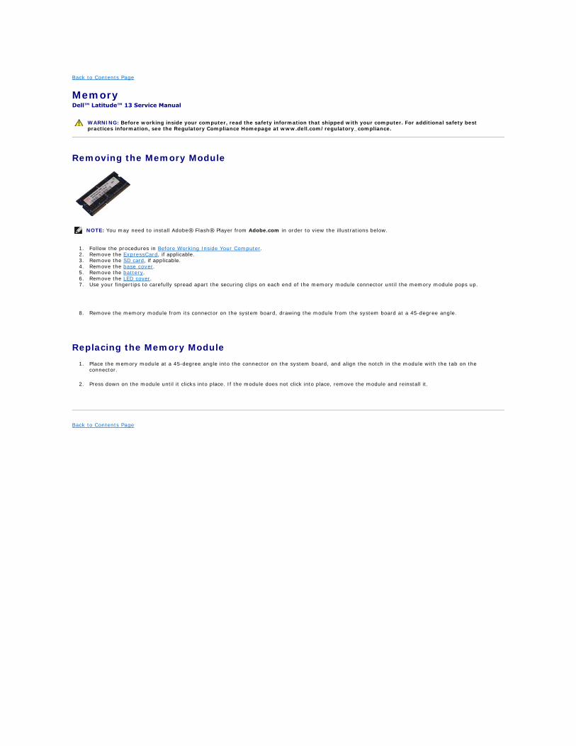
Removing the Memory Module
1. Follow the procedures in Before Working Inside Your Computer. 2. Remove the ExpressCard, if applicable. 3. Remove the SD card, if applicable. 4. Remove the base cover. 5. Remove the battery. 6. Remove the LED cover. 7. Use your fingertips to carefully spread apart the securing clips on each end of the memory module connector until the memory module pops up.
8. Remove the memory module from its connector on the system board, drawing the module from the system board at a 45-degree angle.
Replacing the Memory Module
1. Place the memory module at a 45-degree angle into the connector on the system board, and align the notch in the module with the tab on the connector.
2. Press down on the module until it clicks into place. If the module does not click into place, remove the module and reinstall it.
Back to Contents Page
WARNING: Before working inside your computer, read the safety information that shipped with your computer. For additional safety best practices information, see the Regulatory Compliance Homepage at www.dell.com/regulatory_compliance.
NOTE: You may need to install Adobe® Flash® Player from Adobe.com in order to view the illustrations below.

Back to Contents Page
Palm Rest and Display Assembly Dell™ Latitude™ 13 Service Manual
Removing the Palm Rest and Display Assembly
1. Follow the procedures in Before Working Inside Your Computer. 2. Remove the ExpressCard, if applicable. 3. Remove the SD card, if applicable. 4. Remove the base cover. 5. Remove the battery. 6. Remove the hard drive and audio board. 7. Remove the WLAN card. 8. Remove the LED cover. 9. Remove the memory.
10. Remove the keyboard. 11. Remove the card reader. 12. Remove the coin-cell battery. 13. Remove the system board. 14. Remove the screws on the right of the display hinge.
15. Remove the screws on the left of the display hinge to release the display assembly from the palm rest.
16. Release the antennae, camera, and display cables and remove them from the palm rest.
17. Remove the palm rest from the display assembly.
Replacing the Palm Rest and Display Assembly
To replace the palm rest and display assembly, perform the above steps in reverse order.
Back to Contents Page
WARNING: Before working inside your computer, read the safety information that shipped with your computer. For additional safety best practices information, see the Regulatory Compliance Homepage at www.dell.com/regulatory_compliance.
NOTE: You may need to install Adobe® Flash® Player from Adobe.com in order to view the illustrations below.
Back to Contents Page
LED Cover Dell™ Latitude™ 13 Service Manual
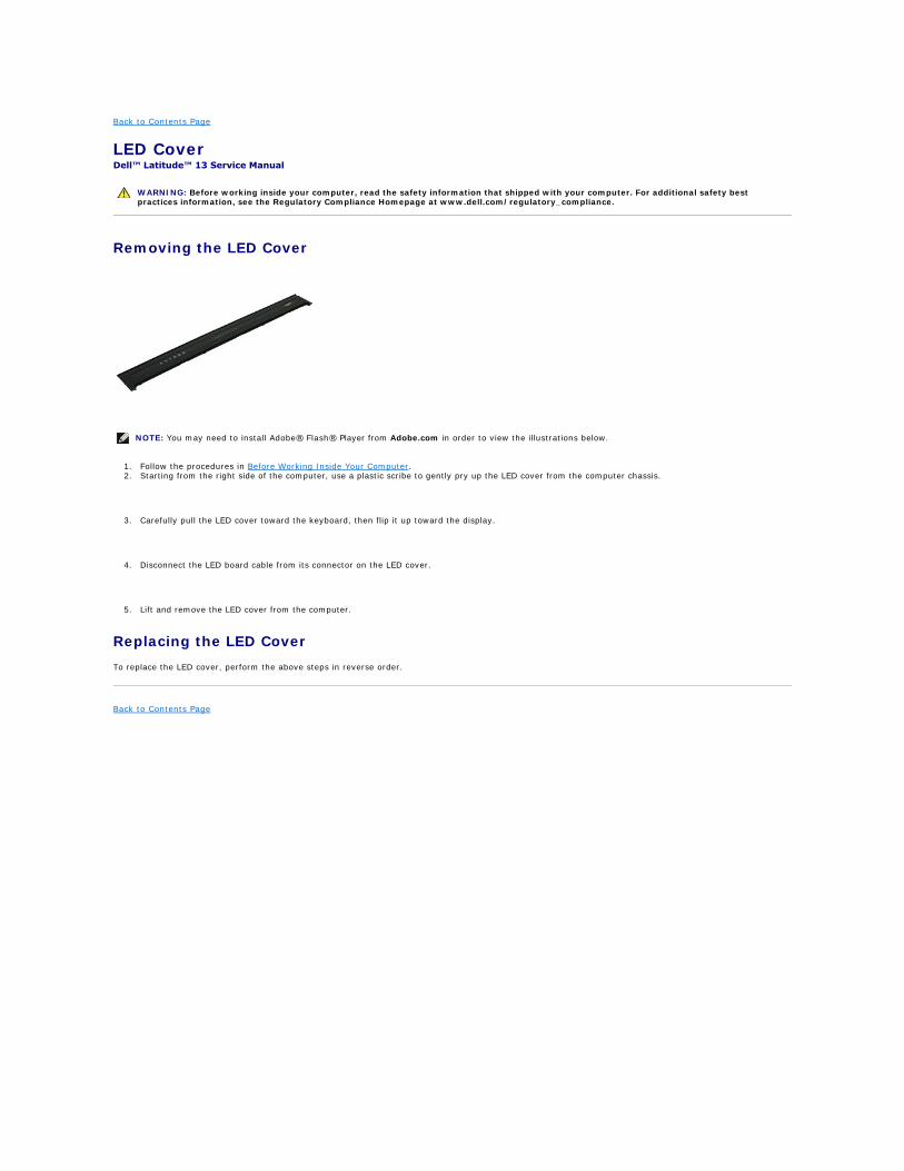
Removing the LED Cover
1. Follow the procedures in Before Working Inside Your Computer. 2. Starting from the right side of the computer, use a plastic scribe to gently pry up the LED cover from the computer chassis.
3. Carefully pull the LED cover toward the keyboard, then flip it up toward the display.
4. Disconnect the LED board cable from its connector on the LED cover.
5. Lift and remove the LED cover from the computer.
Replacing the LED Cover
To replace the LED cover, perform the above steps in reverse order.
Back to Contents Page
WARNING: Before working inside your computer, read the safety information that shipped with your computer. For additional safety best practices information, see the Regulatory Compliance Homepage at www.dell.com/regulatory_compliance.
NOTE: You may need to install Adobe® Flash® Player from Adobe.com in order to view the illustrations below.
Back to Contents Page
Secure Digital (SD) Card Dell™ Latitude™ 13 Service Manual
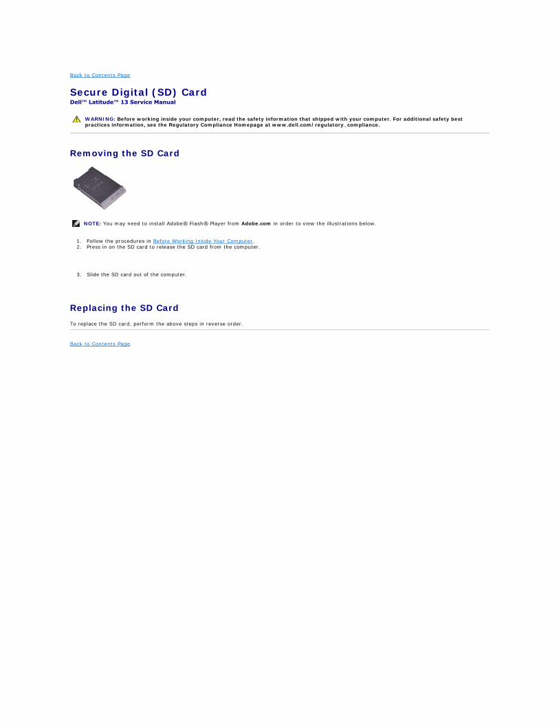
Removing the SD Card
1. Follow the procedures in Before Working Inside Your Computer. 2. Press in on the SD card to release the SD card from the computer.
3. Slide the SD card out of the computer.
Replacing the SD Card
To replace the SD card, perform the above steps in reverse order.
Back to Contents Page
WARNING: Before working inside your computer, read the safety information that shipped with your computer. For additional safety best practices information, see the Regulatory Compliance Homepage at www.dell.com/regulatory_compliance.
NOTE: You may need to install Adobe® Flash® Player from Adobe.com in order to view the illustrations below.

Back to Contents Page
SIM Card Reader Dell™ Latitude™ 13 Service Manual
Removing the SIM Card Reader
1. Follow the procedures in Before Working Inside Your Computer. 2. Remove the ExpressCard, if applicable. 3. Remove the SD card, if applicable. 4. Remove the base cover. 5. Remove the battery. 6. Slide the white latch to disconnect the flex cable from the SIM card reader.
7. Remove the screw that secures the SIM card reader to the computer.
8. Remove the SIM card reader from the computer.
Replacing the SIM Card Reader
To replace the SIM card reader, perform the above steps in reverse order.
Back to Contents Page
WARNING: Before working inside your computer, read the safety information that shipped with your computer. For additional safety best practices information, see the Regulatory Compliance Homepage at www.dell.com/regulatory_compliance.
NOTE: You may need to install Adobe® Flash® Player from Adobe.com in order to view the illustrations below.

Back to Contents Page
Subscriber Identity Module (SIM) Card Dell™ Latitude™ 13 Service Manual
Removing the SIM Card
1. Follow the procedures in Before Working Inside Your Computer. 2. Remove the battery. 3. Remove the LED cover. 4. Remove the keyboard. 5. Slide the SIM card holder and lift it to release the the SIM card from the SIM card holder.
6. Remove the SIM card from the SIM card holder.
Replacing the SIM Card
To replace the SIM card, perform the above steps in reverse order.
Back to Contents Page
WARNING: Before working inside your computer, read the safety information that shipped with your computer. For additional safety best practices information, see the Regulatory Compliance Homepage at www.dell.com/regulatory_compliance.
NOTE: You may need to install Adobe® Flash® Player from Adobe.com in order to view the illustrations below.

Back to Contents Page
Speaker Dell™ Latitude™ 13 Service Manual
Removing the Speaker
1. Follow the procedures in Before Working Inside Your Computer. 2. Remove the ExpressCard, if applicable. 3. Remove the SD card, if applicable. 4. Remove the base cover. 5. Remove the battery. 6. Remove the display closure sensor. 7. Disconnect the touch-pad cable from its connector on the system board.
8. Remove the tape to release the speaker cable from its routing guide in the computer.
9. Disconnect the speaker cable from the audio board and remove it from its routing guide in the computer.
10. Carefully pull up the flex cable and remove it from the speaker.
11. Remove the screws that secure the speaker to the computer.
12. Lift the speaker up and away from the computer.
Replacing the Speaker
To replace the speaker, perform the above steps in reverse order.
Back to Contents Page
WARNING: Before working inside your computer, read the safety information that shipped with your computer. For additional safety best practices information, see the Regulatory Compliance Homepage at www.dell.com/regulatory_compliance.
NOTE: You may need to install Adobe® Flash® Player from Adobe.com in order to view the illustrations below.

Back to Contents Page
System Board Dell™ Latitude™ 13 Service Manual
Removing the System Board
1. Follow the procedures in Before Working Inside Your Computer. 2. Remove the ExpressCard, if applicable. 3. Remove the SD card, if applicable. 4. Remove the base cover. 5. Remove the battery. 6. Remove the hard drive and audio board. 7. Remove the WLAN card. 8. Remove the LED cover. 9. Remove the memory.
10. Remove the keyboard. 11. Remove the card reader. 12. Remove the coin-cell battery. 13. Pull up the blue tab to disconnect the display cable from the system board.
14. Gently turn over the computer and remove the tape to release the antennae cables from the system board.
15. Disconnect the camera cable from the system board.
16. Disconnect the display status sensor and touch-pad flex cables from the system board.
17. Remove the screws that secure the system board and fan to the computer.
18. Remove the system board from the computer.
Replacing the System Board
To replace the system board, perform the above steps in reverse order.
Back to Contents Page
WARNING: Before working inside your computer, read the safety information that shipped with your computer. For additional safety best practices information, see the Regulatory Compliance Homepage at www.dell.com/regulatory_compliance.
NOTE: You may need to install Adobe® Flash® Player from Adobe.com in order to view the illustrations below.

Back to Contents Page
Wireless Local Area Network (WLAN) Card Dell™ Latitude™ 13 Service Manual
Removing the WLAN Card
1. Follow the procedures in Before Working Inside Your Computer. 2. Remove the ExpressCard, if applicable. 3. Remove the SD card, if applicable. 4. Remove the base cover. 5. Remove the battery. 6. Remove the antenna cables from the WLAN card.
7. Remove the screw that secures the WLAN card to the system board.
8. Gently pry the WLAN card from the system board.
9. Pull the WLAN card away from its connector on the system board and remove it from the computer.
Replacing the WLAN Card
To replace the WLAN Card, perform the above steps in reverse order.
Back to Contents Page
WARNING: Before working inside your computer, read the safety information that shipped with your computer. For additional safety best practices information, see the Regulatory Compliance Homepage at www.dell.com/regulatory_compliance.
NOTE: You may need to install Adobe® Flash® Player from Adobe.com in order to view the illustrations below.

Working on Your Computer Dell™ Latitude™ 13 Service Manual
Before Working Inside Your Computer
Use the following safety guidelines to help protect your computer from potential damage and to help to ensure your personal safety. Unless otherwise noted, each procedure included in this document assumes that the following conditions exist:
l You have performed the steps in Working on Your Computer. l You have read the safety information that shipped with your computer. l A component can be replaced or--if purchased separately--installed by performing the removal procedure in reverse order.
To avoid damaging your computer, perform the following steps before you begin working inside the computer.
1. Ensure that your work surface is flat and clean to prevent the computer cover from being scratched. 2. Turn off your computer (see Turning Off Your Computer). 3. If the computer is connected to a docking device (docked), undock it.
4. Disconnect all network cables from the computer. 5. Disconnect your computer and all attached devices from their electrical outlets. 6. Close the display and turn the computer upside-down on a flat work surface.
7. Remove the main battery (see Battery). 8. Turn the computer top-side up. 9. Open the display.
10. Press the power button to ground the system board.
11. Remove any installed ExpressCards or Smart Cards from the appropriate slots. 12. Remove the hard drive (see Hard Drive).
Recommended Tools
The procedures in this document may require the following tools:
l Small flat-blade screwdriver l #0 Phillips screwdriver l #1 Phillips screwdriver l Small plastic scribe l Flash BIOS update program CD
Turning Off Your Computer
1. Shut down the operating system:
Before Working Inside Your Computer
Recommended Tools
Turning Off Your Computer
After Working Inside Your Computer
WARNING: Before working inside your computer, read the safety information that shipped with your computer. For additional safety best practices information, see the Regulatory Compliance Homepage at www.dell.com/regulatory_compliance.
CAUTION: Many repairs may only be done by a certified service technician. You should only perform troubleshooting and simple repairs as authorized in your product documentation, or as directed by the online or telephone service and support team. Damage due to servicing that is not authorized by Dell is not covered by your warranty. Read and follow the safety instructions that came with the product.
CAUTION: To avoid electrostatic discharge, ground yourself by using a wrist grounding strap or by periodically touching an unpainted metal surface, such as a connector on the back of the computer.
CAUTION: Handle components and cards with care. Do not touch the components or contacts on a card. Hold a card by its edges or by its metal mounting bracket. Hold a component such as a processor by its edges, not by its pins.
CAUTION: When you disconnect a cable, pull on its connector or on its pull-tab, not on the cable itself. Some cables have connectors with locking tabs; if you are disconnecting this type of cable, press in on the locking tabs before you disconnect the cable. As you pull connectors apart, keep them evenly aligned to avoid bending any connector pins. Also, before you connect a cable, ensure that both connectors are correctly oriented and aligned.
NOTE: The color of your computer and certain components may appear differently than shown in this document.
CAUTION: To disconnect a network cable, first unplug the cable from your computer and then unplug the cable from the network device.
CAUTION: To avoid damaging the system board, you must remove the main battery before you service the computer.
CAUTION: To guard against electrical shock, always unplug your computer from the electrical outlet before opening the display.
CAUTION: Before touching anything inside your computer, ground yourself by touching an unpainted metal surface, such as the metal at the back of the computer. While you work, periodically touch an unpainted metal surface to dissipate static electricity, which could harm internal components.
CAUTION: To avoid losing data, save and close all open files and exit all open programs before you turn off your computer.

l In Windows Vista®:
Click Start , then click the arrow in the lower-right corner of the Start menu as shown below, and then click Shut Down.
l In Windows® XP:
Click Start® Turn Off Computer® Turn Off.
The computer turns off after the operating system shutdown process is complete.
2. Ensure that the computer and all attached devices are turned off. If your computer and attached devices did not automatically turn off when you shut down your operating system, press and hold the power button for about 6 seconds to turn them off.
After Working Inside Your Computer
After you complete any replacement procedure, ensure you connect any external devices, cards, and cables before turning on your computer.
1. Connect any external devices, such as a port replicator, battery slice, or media base, and replace any cards, such as an ExpressCard.
2. Connect any telephone or network cables to your computer. 3. Replace the battery. 4. Connect your computer and all attached devices to their electrical outlets. 5. Turn on your computer.
Back to Contents Page
CAUTION: To avoid damage to the computer, use only the battery designed for this particular Dell computer. Do not use batteries designed for other Dell computers.
CAUTION: To connect a network cable, first plug the cable into the network device and then plug it into the computer.
Recommended


![6HUYLVQtS tUX þND'HOO /DWLWXGH€¦ · 6HUYLVQtS tUX þND'HOO /DWLWXGH 3R]QiPN\ XSR]RUQ QtDYêVWUDK\ Pokud jste zakoupili po þtWDþ DG\'HOO Q QHSODWtSURYiV åiGQêRGND]QDRSHUD þQtV\VWpP0LFURVRIW](https://img.dokumen.tips/doc/110x75/5f996ae52c6dd0736a16639a/6huylvqts-tux-ndhoo-dwlwxgh-6huylvqts-tux-ndhoo-dwlwxgh-3rqipn-xsrruq.jpg)


