Department of Chemical Engineering
Heat Transfer Mechanisms in an Indirectly Heated Rotary Kiln with
Lifters and Its Role in Scaling
Iwan Harsono Hwan
This thesis is presented for the Degree of
Doctor of Philosophy
of
Curtin University of Technology
April 2009
i
Declaration
To the best of my knowledge and belief this thesis contains no material previously
published by any other person except where due acknowledgment has been made.
This thesis contains no material which has been accepted for the award of any other
degree or diploma in any other university.
Signature : …………………………
Date : …………………………

ii
Dedications
To my wife, Nancy, my children, Kenzo - Keiko, my cheerleaders

iii
Abstract
This present research aims to obtain a fundamental understanding on solid transport,
solid mixing and the complex heat transfer mechanisms related to the important
installed segmented lifter in an indirectly heated rotary kiln. To accomplish these
objectives in a systematic manner, the experimental and modelling studies on solid
transport and mixing were first carried out in pilot-scale cold kilns at Curtin
University of Technology, Perth, Western Australia then followed by heat transfer
study in a pilot-scale hot kiln system available at ANSAC Pty Ltd, Bunbury, Western
Australia.
For design and scaling purposes, dimensional analysis was carried out. A series of
experiments in cold kilns were also carried out, considering lifter design, lifter
configurations, helix, a wide-range of solid and various kiln designs under different
kiln operating conditions. The results showed that a flat bed depth profile can be
achieved using purposely-designed segmented lifters at favourable practical low Reω
values (less energy input to drive the kilns and more throughputs), with a low total
kiln filling fraction and a high degree of axial mixing (Pe < 50 or Dz = 10-5
- 10-3
m2/s). This is essential to good heat transfer performance. The effects of helix, L/D,
Fr and d/D have relatively insignificant differences on solid transport and mixing
under the current experimental conditions. These findings demonstrate the unique
advantages of the purposely-designed segmented lifters compared to other
conventional lifters (e.g. single throughout lifters), providing important information
for scaling criteria and modelling work.
A preliminary DEM simulation, as an emerging simulation tool at a particle level,
confirmed that axial displacement is mainly due to the function of the folded lifter
sections of the segmented lifters. The folded lifter sections push the solids towards
the kiln discharge end along the bed arc length and such effect increases as Reω
increases. This finding leads to the development of a transport model, limited to
underloading regimes, to predict the average bed depth in this type of kilns. The
iv
model predictions are in good agreement with experimental data. A set of global
power-law dimensionless empirical correlations on solid transport and mixing,
applicable to all three (over-, design-, underloading) regimes, were also developed
based on the data obtained from our systematic experiments. The validity was tested
with data presented in selected previous studies. It is found that the developed
correlations are largely specific to the present lifter design and configurations.
A steady-state axial heat transfer model has also been developed for a kiln with
segmented lifters. The model predicts the temperature profiles at inner heat tube, in
the freeboard gas, in the bed, on the tube wall and the outer heat tube in the flue gas.
The model incorporates developed solid transport and mixing correlations, as well as
suitable heat transfer modes and reaction model. It takes the form of ordinary
differential equations which were solved numerically. The input data necessary for
the model were obtained by our own experiments and/or extracted from the
literature. The model was validated by the temperature profiles obtained from the hot
kiln. Among the heat transfer modes considered, it is found that the limiting step of
heat transfer in the kiln is the heat transfer from covered inner kiln wall to covered
bed, which is highly influenced by solid transport and mixing. Under the current
experimental conditions, the typical overall heat transfer coefficient was found to be
31 - 35 W/m2.K.
The present research advances the fundamental understanding on solid transport,
solid mixing and the complex heat transfer mechanisms in an indirectly heated rotary
kiln with segmented lifters. The obtained data and knowledge are important to
improve the kiln energy efficiency, reduce kiln manufacture and operation costs and
widen the kiln applications at different scales.
Due to nature of this thesis, chapter 6 is confidential for the first three-year based on
a confidentiality agreement with industrial partner.
v
Acknowledgments
Completing a PhD is truly a marathon event and would not be possible if it is an
individual task. I would not have been able to complete this journey without the
tireless assistance, encouragement and contributions of the following individuals and
organizations:
Associate Professor Hongwei Wu, as my supervisor, for his unstinting commitment
to helping see this project through to its final completion. He provided me with
direction to follow, technical support, perceptive feedback and especially for the
enthusiasm which he invoked within me. Again, thank you for giving me examples
how to become a truly good researcher in the academic world and caring my future
career. My hope is that in future we will be able to keep regular contact and
strengthen the friendship we have established here.
From the industrial partner, special thanks to Matthew Martella, Managing Director,
ANZAC Pty Ltd, for providing me with pilot-scale experimental rigs. I would like to
thank for his contribution for the fruitful discussions on the industrial perspective in
this project. The support and assistance of Aron Abolis, Engineering Manager and
Gavin de Bres, Projects Manager, ANSAC Pty Ltd during the hot kiln test is also
gratefully acknowledged.
My deepest appreciation is given for those who have contributed in either the
experimental, data processing and/or preliminary modelling work for both cold and
hot kilns. Firstly to the Faculty and Department workshop staff, Karen Haynes, John
Murray, David Collier and Michael Ellis, for help with the construction of helixes
and lifters at different configurations; and modification of cold kilns. To Dr Huiling
Wee, Dr Hamzah Fansuri, Syamsuddin Yani, Gunawan Wibisono and Henny Yap,
who assisted in part of the lab work and/or image processing. To 4th
year students
under ChE49x research project units, Steven Rule, Sandi Ma, Shunyin Chng, Chin
Yen Pui, Ahmad Badarani, Moiz Alibhai, Young L. Pang, Kee L. Pau, Mohd A.M.

vi
Sabri and Tasha A. Yahya, for their assistance in the lab and image processing work,
Edward Ee in the solid transport modelling work, Andrew Barycki in the DEM
simulation work, Jonathan Khoo and Jonathan Chi Yong Teoh in the heat transfer
modelling work and William Hendrawinata and Xiangpeng Gao in setting up the
data takers.
My PhD period in the Chemical Engineering Department is one of the best times in
my life, and I would like to thank all my colleagues who have shared it with me:
Johan Utomo, Agus Saptoro, Dr Richard R. Gunawan and Dr Kong Vui Yip for
being my partners in the academics and spiritual discussion; Shariff Ibrahim, Pradeep
K. Shukla, and Nurul Widiastuti for being good partners in the laboratory; Jann
Bolton and Naomi Tokisue for the administrative support.
Perth is a city with a large population of Indonesia community. Some of them have
shared their best time with me: Herman Yapeter, Dani Pranoto, Uras T. Palis, Iman
Faskayana, Hanny H. Tumbelaka, Johan Utomo and their families for the best cell
group I ever had; Christian friends, especially Pastor Paulus Surya, at WPC in Bull
Creek and my friendly neighbours at Toledo in East Victoria Park.
I must acknowledge my wife (Nancy Hendradjaja), my children (Kenzo and Keiko),
Papa and Mama, my mother- and father-in-law for the strong continuous moral
support, encouragement, understanding and immeasurable love during my 3.5 years
of PhD study overseas. I hope I have done something which makes you proud.
Financial and other supports received for this research from the Australian Research
Council, ANZAC Pty Ltd through the ARC Linkage Projects Scheme and CIRTS
scholarship from Curtin University of Technology is gratefully acknowledged.
Thank you Christ Jesus as Lord over all things for guiding me the way of life You
would have me to go.
vii
Table of Contents
Declaration ................................................................................................................ i
Dedications............................................................................................................... ii
Abstract ................................................................................................................ iii
Acknowledgments ....................................................................................................v
Table of Contents ....................................................................................................vii
List of Figures ...........................................................................................................x
List of Tables ..........................................................................................................xv
Chapters
1 Introduction ..................................................................................................1
1.1 Industrial Background ...........................................................................1
1.2 Thesis Objectives and Structure ............................................................3
1.2.1 Thesis Objectives .....................................................................3
1.2.2 Thesis Structure .......................................................................4
2 Literature Review ..........................................................................................6
2.1 Solid Transport .....................................................................................6
2.1.1 Modelling .................................................................................7
2.1.2 Experimental .............................................................................9
2.2 Solid Mixing .......................................................................................11
2.2.1 Modelling ...............................................................................12
2.2.2 Experimental ...........................................................................14
2.3 Heat Transfer ......................................................................................16
2.3.1 Modelling ...............................................................................17
2.3.2 Experimental ...........................................................................20
2.4 Summary ............................................................................................25
3 Methodology ..............................................................................................27
3.1 Dimensional analysis .......................................................................... 29
3.2 Granular solid .................................................................................... 29
3.3 Rotary kilns ....................................................................................... 31
3.3.1 Cold kilns ................................................................................31
viii
3.3.2 Lifters .....................................................................................33
3.3.3 A hot kiln .................................................................................35
3.4 Image processing ................................................................................37
3.5 Experimental methods ........................................................................38
3.5.1 Solid transport ........................................................................38
3.5.2 Solid mixing ............................................................................ 40
3.5.3 Heat transfer........................................................................... 41
3.6 Modelling ...........................................................................................42
3.7 Summary ............................................................................................43
4 Solid Transport ............................................................................................44
4.1 Effect of segmented lifter design, lifter configurations and helix on
transport prediction equations and axial bed depth profile................... 44
4.1.1 Inclined kiln without lifters ......................................................46
4.1.2 Lifter configurations ................................................................49
4.1.3 Folded lifter section ................................................................ 51
4.1.4 Axis straight lifter slope ..........................................................52
4.1.5 Number of lifters per row ........................................................53
4.1.6 Helix ....................................................................................... 56
4.2 Effect of design equations on transport prediction equations in
horizontal rotating kilns with segmented lifters....................................60
4.2.1 Dynamic ratios.........................................................................60
4.2.2 Solid characteristics ................................................................61
4.2.3 Geometric ratios ......................................................................62
4.3 Modelling ...........................................................................................64
4.3.1 A preliminary DEM simulation ............................................... 64
4.3.2 Development of a bed depth prediction model .........................71
4.3.3 Development of dimensionless empirical correlations ............. 77
4.3.4 Comparison with selected previous transport experimental
studies..................................................................................... 78
4.4 Summary ............................................................................................ 81
5 Solid Mixing ............................................................................................... 83
5.1 Effect of segmented lifter design, lifter configurations and helix on a
mixing prediction equation .................................................................84
ix
5.1.1 Inclined kiln without lifters..................................................... 84
5.1.2 Lifter configurations ............................................................... 86
5.1.3 Folded lifter section ................................................................ 86
5.1.4 Number of lifters per row ........................................................ 88
5.1.5 Helix ....................................................................................... 89
5.2 Effect of design equations on prediction equation in a horizontal
rotating kiln with segmented lifters ..................................................... 90
5.2.1 Dynamic ratios ........................................................................91
5.2.2 Solid characteristics ................................................................92
5.2.3 Geometric ratios .................................................................... 93
5.3 Modelling ...........................................................................................94
5.3.1 Development of a dimensionless empirical correlation ............94
5.3.2 Comparison with selected previous mixing experimental
studies .....................................................................................97
5.4 Summary ..........................................................................................100
6 Heat Transfer ............................................................................................101
6.1 Development of integrated mechanisms ............................................101
6.1.1 Heat transfer modes ..............................................................102
6.1.2 Reaction rate model ..............................................................104
6.1.3 Energy and mass balances ....................................................105
6.1.4 Validation .............................................................................111
6.2 Summary ..........................................................................................117
7 Conclusions and Recommendations ...........................................................119
7.1 Conclusions ......................................................................................119
7.2 Recommendations ............................................................................121
Nomenclature .......................................................................................................122
References ............................................................................................................126

x
List of Figures
Figure 1.1 Heat transfer modes inside and outside in an ANSAC indirectly
heated rotary kiln at (a) transversal and (b) axial directions. (do
not scale)
2
Figure 2.1 Schematic of the bed cross-section under rolling bed motion in
rotary kilns without lifters
7
Figure 2.2 A discrete slice of a rotary kiln showing the definition of the (a)
underloaded, (b) design loaded and (c) overloaded kilns
8
Figure 2.3 Schematic of attached (a) single throughout lifter and (b)
segmented lifters in an axial slice of rotary kilns.
11
Figure 3.1 Research methodology 28
Figure 3.2 A schematic diagram of the cold-kiln experimental system: (a)
hoppers, (b) feeding plate, (c) fix end constriction (d) rotary kiln,
(e) removable windows (f) screw feeders, (g) removable lifters
and (h) house jack
32
Figure 3.3 Design and configurations of removable segmented lifters and
helix in a horizontal rotating kiln with L/D ratio of 10. (do not
scale)
33
Figure 3.4 Designs and configurations of lifters per row with hl/D ratio of
0.16 in a horizontal rotating kiln with L/D ratio of 7: (a) single
throughout lifters 80 x 2840 mm, (b) horizontal straight lifters 80
x 270 mm, (c) inclined straight lifters 80 x 270 mm and (d) 7
lifters and (e) 4 (out of 7) lifters. (do not scale)
34
Figure 3.5 Pilot plant basic flow sheet (do not scale) 35
Figure 3.6 A pilot hot kiln showing the designated (a) transverse and (b)
axial locations of the thermocouples: (1) flue gas, (2) outer wall,
(3) inner wall, (4) bed, (5) lifter and (6) freeboard gas. (do not
scale)
37
Figure 3.7 Image processing steps to get the threshold of the surface tracer
fractions: (a) original image in RGB colour, (b) tracers/bulk
mixtures without visible kiln wall and lifters, (c) surface area of
black tracers, (d) surface area of black tracers/bulk mixtures
38

xi
Figure 3.8 Comparison of Pe profiles based on half and quarter opening
windows in horizontal rotating kilns with segmented lifters (hl/D
= 0.08): (a) L/D = 10, Reω = 1353, (b) L/D = 5, Reω = 2818
41
Figure 4.1 The f, h and Culocal of sand in a rotary kiln (L/D = 7) without and
with segmented lifters (hl/D = 0.16): (a) f vs Reω at different axis
kiln slopes without and with segmented lifters; h and Culocal vs
z/L under various Reω in: (b) a horizontal kiln without lifters, (c)
an inclined kiln without lifters, (d) a horizontal kiln with
segmented lifters
48
Figure 4.2 The f and h of glass bead in a horizontal rotating kiln (L/D = 7):
(a) f vs Reω at different lifter configurations; h vs z/L at various
Reω with: (b) single throughout lifters and (c) segmented lifters
50
Figure 4.3 The f and h of glass bead in a horizontal rotating kiln (L/D = 7):
(a) f vs Reω at different segmented lifters, (b) h vs z/L at various
Reω with segmented straight lifters
51
Figure 4.4 The f and h of sand and glass bead in a horizontal rotating kiln
(L/D = 7): (a) f vs Reω at different lifter types; h vs z/L at various
Reω and lifter slopes: (b) glass bead and (c) sand
54
Figure 4.5 The f and h of glass bead in a horizontal rotating kiln (L/D = 7):
(a) Reω vs f at different segmented lifter numbers per row and (b)
h vs z/L at various Reω with four segmented lifters per row
55
Figure 4.6 The f of glass bead and sand in horizontal rotating kilns with
segmented lifters (hl/D = 0.16) and with or without helix at
different Reω in horizontal rotating kilns with: (a) L/D = 5 and
(b) L/D = 10
56
Figure 4.7 The axial bed depth profiles in horizontal rotating kilns with
segmented lifters and with or without helix at different Reω of (a)
glass bead and (b) sand in a kiln with L/D = 10; (c) glass bead
and (d) sand in a kiln with L/D = 5
57
Figure 4.8 The f and Cu in dependence on the Reω at underloading regime in
a horizontal rotating kiln (L/D = 7) with segmented lifters (hl/D
= 0.16) (ο = glass beads, � = sand)
59
Figure 4.9 The f in dependence on the Reω at underloading regime in a
horizontal rotating kiln (L/D = 7) with segmented lifters (hl/D =
0.16) (urea: + = 2 mm, ο = 3 mm, � = 4 mm)
60
Figure 4.10 The f and Cu in dependence on the Reω at various solid in a
horizontal rotating kiln (L/D = 7) with segmented lifters (hl/D =
61
xii
0.08)
Figure 4.11 The f in dependence on the Reω at various solid in a horizontal
rotating kiln (L/D = 7) with segmented lifters (black: hl/D =
0.16, red: hl/D = 0.08).
64
Figure 4.12 The f in dependence on the Reω at various kilns designs (L/D: ο
= 5, + = 7, � = 10) with segmented lifters (hl/D = 0.16): (a) glass
bead, (b) coriander seed, (c) rice, (d) urea 3 mm, (e) sand
65
Figure 4.13 Orientation snapshot of a horizontal rotating kiln used for the
simulation with particles as vectors, installed segmented lifters
(hl/D = 0.16), feeding plate, virtual dynamic surface particle
factory and binning zones
67
Figure 4.14 Binning zones with 22 zones along the z-direction from 50 to
1100 mm, 1 zone on the y-direction from -225 to 252 mm and 3
zones across the x-direction from -50 to 80 mm
67
Figure 4.15 Axial velocity profiles from 75s to 78s 69
Figure 4.16 Top view snapshots of axial velocity profiles from 75s to 78s 70
Figure 4.17 Segmented lifter configurations between row 71
Figure 4.18 Sketch of the kiln cross-section 73
Figure 4.19 Sketch of the lifter structure with two triangular prisms Nf 73
Figure 4.20 Displaced axial volume per folded lifter section along the bed
arc length
74
Figure 4.21 Plot of calculated vs. measured h in horizontal rotating kilns
with segmented lifters at underloading regimes
76
Figure 4.22 Plot of calculated vs. measured f and Cu 78
Figure 4.23 The f and Cu in dependence on the Reω at different authors 79
Figure 5.1 The Pe and Cτ of urea in a rotary kiln (L/D = 7) without and with
segmented lifters (hl/D = 0.16) at Reω = 3692: (a) Pe vs z/L and
(b) Cτ vs z/L.
85
Figure 5.2 The Pe and Cτ profiles of urea in a rotary kiln (L/D = 7) without
lifters and with single throughout lifters and segmented lifters
(hl/D = 0.16) at Reω = 3692: (a) Pe vs z/L and (b) Cτ vs z/L.
87
xiii
Figure 5.3 The Pe and Cτ profiles of urea in a rotary kiln (L/D = 7) with
and without folded lifter sections (straight) segmented lifters
(hl/D = 0.16) at Reω = 3692: (a) Pe vs z/L and (b) Cτ vs z/L.
88
Figure 5.4 The Pe and Cτ profiles of urea in a rotary kiln (L/D = 7) at two
different numbers of lifters per row (hl/D = 0.16) at Reω = 3692:
(a) Pe vs z/L and (b) Cτ vs z/L.
89
Figure 5.5 The Pe and Cτ profiles of urea in a rotary kiln (L/D = 5) with
segmented lifters (hl/D = 0.16) and with or without helix at Reω
= 2818: (a) Pe vs z/L and (b) Cτ vs z/L.
90
Figure 5.6 The Pe and Cτ profiles of urea in a rotary kiln (L/D = 10) with
segmented lifters (hl/D = 0.16) and with or without helix at Reω
= 1353: (a) Pe vs z/L and (b) Cτ vs z/L
91
Figure 5.7 The Pe as a function of Reω at z/L = 0.8 in a rotating kiln (L/D =
7) with segmented lifters (hl/D = 0.16) using glass bead
92
Figure 5.8 The Pe as a function of Reω at at z/L = 0.8 in a rotating kiln (L/D
= 7) with segmented lifters (hl/D = 0.16) at various solid
93
Figure 5.9 The Pe as a function of Reω at at z/L = 0.8 in a rotating kiln (L/D
= 7) with different segmented lifter heights (0.08 and 0.16): (a)
urea and (b) coriander seed
94
Figure 5.10 The Pe as a function of Reω in a rotating kiln (L/D = 7) at various
z/L and solid with two different segmented lifter heights: (a) hl/D
= 0.16 and (b) hl/D = 0.08.
96
Figure 5.11 Plot of calculated vs. measured Pe at z/L = 0.8 97
Figure 5.12 The Pe in dependence on the Reω at different authors 98
Figure 5.13 The f in dependence on the Reω at different authors 98
Figure 6.1 A schematic diagram of a horizontal indirectly-heated rotary kiln
with segmented lifters. (Do not scale)
105
Figure 6.2 Flow diagram of the heat transfer model 110
Figure 6.3 Comparison of predicted axial temperature profiles by the one-
dimensional model and experimental data: (a) mb = 260 kg/h, mf
= 260 kg/h and (b) mb = 365 kg/h, mf = 234 kg/h
111
Figure 6.4 Predicted volatile species concentration profiles and its
comparison with experimental data (∆ = measured at mb = 260
114
xiv
kg/h, � = measured at mb = 325 kg/h)
Figure 6.5 Net heat fluxes outside and inside kiln from different modes of
transfer: (a) mb = 260 kg/h and (b) mb = 365 kg/h
115
Figure 6.6 Contribution of various heat transfer modes inside the kiln:
(a) mb = 260 kg/h and (b) mb = 365 kg/h.
116

xv
List of Tables
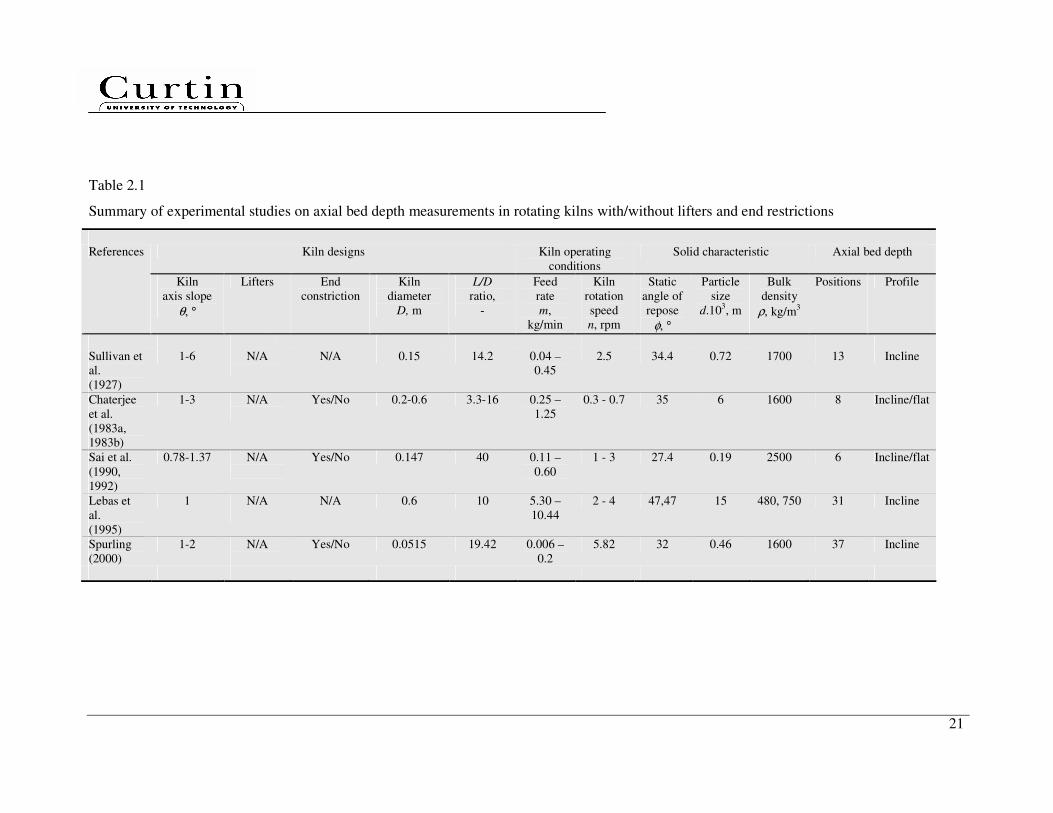
Table 2.1 Summary of experimental studies on axial bed depth
measurements in rotating kilns with/without lifters and end
restrictions
21
Table 2.2 Summary of experimental studies on total hold-up measurements
in rotating kilns
22
Table 2.3 Summary of experimental studies on axial dispersion coefficient
measurements in rotating kilns
23
Table 2.4
Summary of experimental studies on axial heat transfer in rotary
kilns
24
Table 3.1 Granular solids used in the experimental studies in cold kilns 30
Table 3.2 Tracers used for mixing experimental studies in cold kilns 30
Table 3.3 A low-rank coal sample used for experimental studies in a hot
kiln
31
Table 4.1 Parameters used for the DEM-based simulation 66
Table 4.2 Range of input dimensionless group on solid transport by
authors for developing correlations
81
Table 5.1 Range of input dimensionless group on solid mixing by authors
for developing correlations
99
Table 6.1 Correlations of various basic heat transfer coefficients (W/m2.K) 102
Table 6.2 Parameter values used during the simulations 112
1
Chapter 1
Introduction
1.1 Background
Rotary kilns play an important role in diverse industrial applications, especially in
the processing of coarse or free-flowing solid in the chemical, metallurgical ores,
mineral, pharmaceutical, ceramics, cement, polymers, food, fertilizer and waste
process industries. They are used in operations such as mixing, heating, cooling,
reacting and drying of solid or combination of theses operations. The wide use of
kilns can be attributed to major factors such as the ability to handle an extensive
range of feed physical properties and the flexible adjustment of residence time in a
continuous operation mode involving heterogeneous reactions.
Rotary kilns used in industry vary greatly in heating modes, kiln axis slopes and lifter
types. The kilns can be either directly or indirectly heated. In a directly heated kiln,
fuel (coal, gas or oil) goes through combustor or burner where it is mixed with
oxygen to generate high temperature gas. The hot gas is then introduced into the kiln
in a direction either co-current or counter-current to the solid flow. However, in an
indirectly heated kiln, the heat tube is housed in casing and the combustion occurs
with the case but external to the kiln while the solid is processed inside the kiln.
Therefore, indirect heating of kilns provide clean heating and flexible in controlling
the heat transfer for solid.
ANSAC is a wholly owned Australian company engaged in the development, design,
manufacture and supply of quality engineered thermal process equipment for
applications in the industrial and mining markets. ANSAC’s core competencies are
2
in the specialised engineering fields of combustion, heat transfer, high temperature
materials engineering, solids and materials handling, mechanical component design
and horizontal rotating elements.
The ANSAC indirectly heated rotary kiln typically operates at 873-1073°K. This kiln
is not inclined, achieving excellent mechanic performance. Compared to most
conventional single throughout lifters, the ANSAC lifters consist of a number of
segments. These lifters may provide three key functions, enhancing solid transport,
mixing and heat transfer inside the kiln.
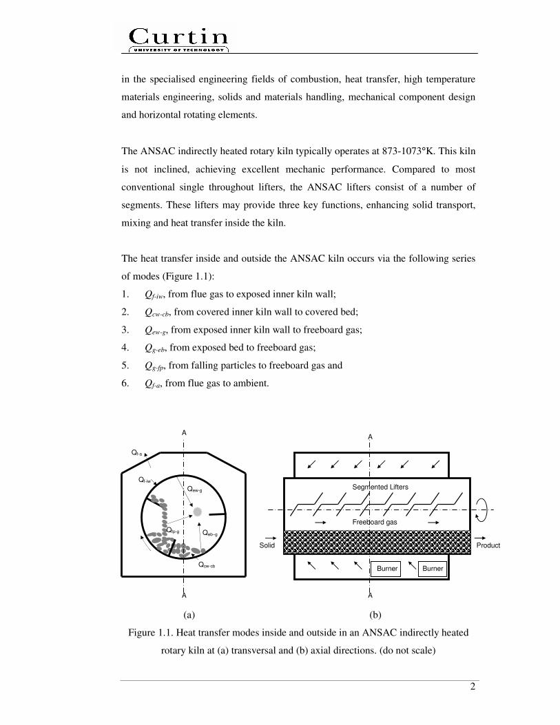
The heat transfer inside and outside the ANSAC kiln occurs via the following series
of modes (Figure 1.1):
1. Qf-iw, from flue gas to exposed inner kiln wall;
2. Qcw-cb, from covered inner kiln wall to covered bed;
3. Qew-g, from exposed inner kiln wall to freeboard gas;
4. Qg-eb, from exposed bed to freeboard gas;
5. Qg-fp, from falling particles to freeboard gas and
6. Qf-a, from flue gas to ambient.
(a) (b)
Figure 1.1. Heat transfer modes inside and outside in an ANSAC indirectly heated
rotary kiln at (a) transversal and (b) axial directions. (do not scale)
Product
Burner Burner
Solid
Segmented Lifters
Freeboard gas
A
A
Qf-a
A
Qew-g
Qeb–g
Qcw-cb
Qfp-g
Qf-iw
A
3
Each mode may involve one or more heat transfer mechanisms. The relative
importance of these modes determining the overall heat transfer which is function of
the solid thermo-physical properties, kiln designs, operating and process conditions.
Among the abovementioned heat transfer in an ANSAC kiln, steps b), d) and e) play
crucial role. This is determined by the complex motion and mixing of the solid which
is known to be one of the major challenges facing the kiln designing and scaling.
A good understanding of the complex heat transfer mechanisms in the ANSAC kiln
potentially will lead to energy efficiency improvement, reduction in costs of kiln
manufacture and operation as well as widen its applications at different scales.
However, the controlling steps in heat transfer have not been fully understood.
Moreover, no suitable simple, quick and reliable predictive tools as well as scaling
criteria have been developed for this kiln, as a foundation for the purpose of process
design, development and operation of any practical utilisation of this kiln.
1.2 Thesis Objectives and Structure
1.2.1 Thesis Objectives
This research is jointly developed by the collaborating partners between Curtin
University of Technology, Perth, Western Australia and ANSAC Pty Ltd, Bunbury,
Western Australia. This present research aims to obtain a fundamental understanding
of the complex heat transfer mechanisms in an indirectly heated rotary kiln with
segmented lifters and its role in scaling through experimental and modelling studies.
Following the understanding of the heat transfer mechanisms, semi-empirical models
and criteria will be developed to serve as a predictive tool for simple, quick and
reliable kiln designing and scaling. The study focuses on the influences of the solid
transport and mixing as well as heat transfer modes where appropriate.

4
1.2.2 Thesis Structure
Including this chapter, there are a total of 7 chapters in this thesis. Each chapter is
outlined as follows:
• Chapter 1 gives an overview of the thesis.
• Chapter 2 reviews the current state of knowledge on this subject in literature,
including solid transport, mixing and heat transfer through experimental and
modelling studies. Chapter 2 then identifies the key research gaps and specific
objectives for the present research.
• Chapter 3 describes the overall methodology employed in this study, along with
the explanations of the experimental and modelling techniques used.
• Chapter 4 presents the results of the experimental and modelling studies on
solid transport in cold kilns. Effects of segmented lifter design configurations
and helix on transport prediction equations and axial bed depth profiles are
investigated. The data shows that the segmented lifters enhance axial solid
transport and lead to flat bed depth profiles. Chapter 4 also shows results from
the preliminary DEM simulation and development of a transport model as well
as dimensionless empirical transport correlations. Attempts have also been
made to compare the results in this study with those in relevant previous
studies.
• Chapter 5 reports the results of the effects of segmented lifter design, lifter
configurations and helix on solid mixing. The data show that the segmented
lifters enhance axial solid mixing and transport, leads to the development of a
dimensionless empirical mixing correlation. Attempts have also been made to
compare the results in this study with those in relevant previous studies.

5
• Chapter 6 offers a fully integrated steady state axial heat transfer model in an
indirectly heated rotary kiln with segmented lifters. The model incorporates
developed solid transport and mixing correlations, as well as suitable heat
transfer modes and reaction rate model for a low-rank coal pyrolysis case. The
model has been validated by hot kiln experimental data. The controlling steps
in heat transfer, overall heat transfer coefficient and heat transfer efficiency are
then determined.
• Chapter 7 presents the conclusions over the whole study and outlines
recommendations for future research and development.
6
Chapter 2
Literature Review
Extensive experimental and modelling efforts have been made in order to understand
heat transfer mechanisms in rotary kilns. It is necessary to establish a solid
knowledge base for the present study by examining the information available on this
subject. This chapter reviews the previous work on the fundamentals of the solid
transport, mixing and heat transfer in continuous systems. Through a critical
evaluation of the previous work, the key research gaps in these areas are then
identified, assisting in defining the specific objectives of the present study.
2.1 Solid Transport
There are two components in the transport of the granular solid through the kiln, the
transport that occurs in a transverse section, perpendicular to the kiln axis, and the
transport taking place along the kiln axis. While the first is important to the
homogeneity of the solid bed, the second is critical in determining the bed profile and
the mean residence time of the solid in the kiln.
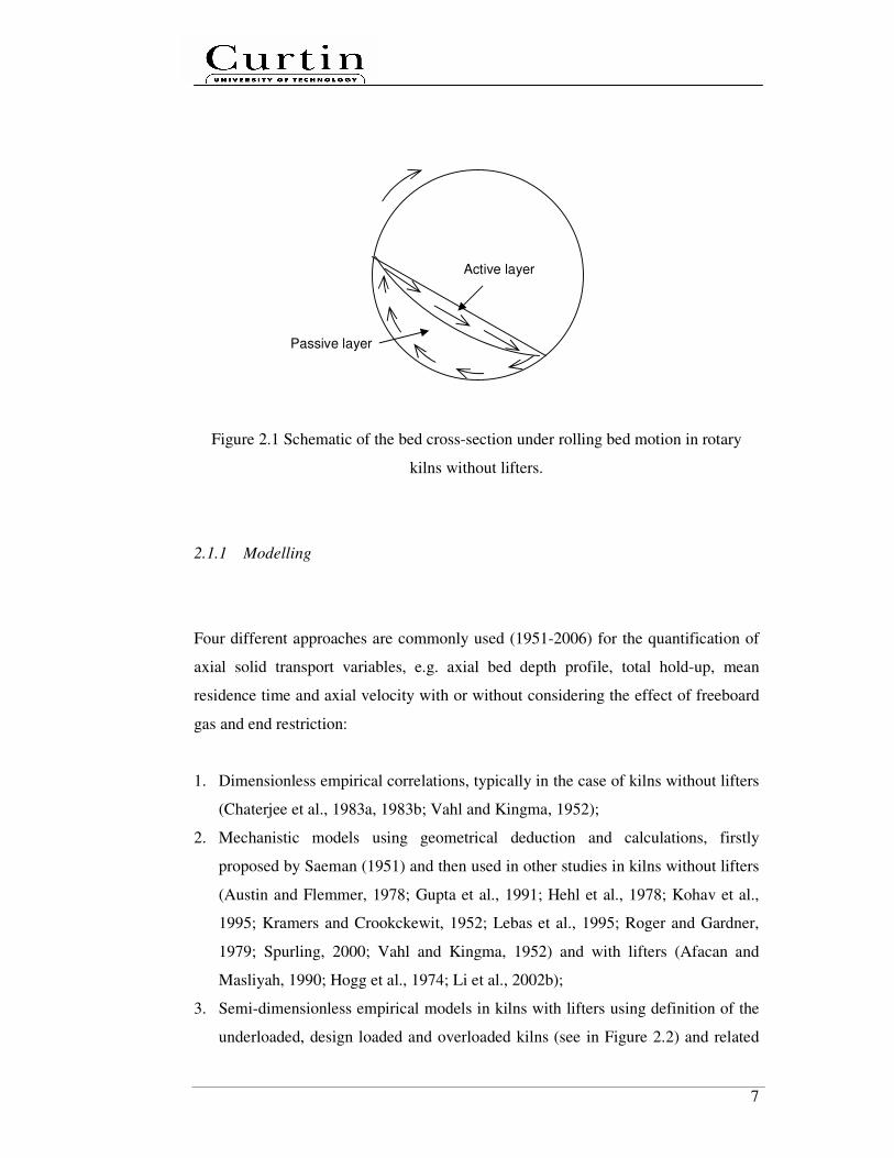
The prevailing form of solid transversal motion in rotating kilns without lifters is
rolling motion (see in Figure 2.1). This type of motion is characterized by a uniform,
static flow of a particle layer on the surface (active layer), while the larger part of the
bed (passive layer) is transported upwards by solid body rotation with the rotational
speed of the wall (Mellmann, 2001).
7
Figure 2.1 Schematic of the bed cross-section under rolling bed motion in rotary
kilns without lifters.
2.1.1 Modelling
Four different approaches are commonly used (1951-2006) for the quantification of
axial solid transport variables, e.g. axial bed depth profile, total hold-up, mean
residence time and axial velocity with or without considering the effect of freeboard
gas and end restriction:
1. Dimensionless empirical correlations, typically in the case of kilns without lifters
(Chaterjee et al., 1983a, 1983b; Vahl and Kingma, 1952);
2. Mechanistic models using geometrical deduction and calculations, firstly
proposed by Saeman (1951) and then used in other studies in kilns without lifters
(Austin and Flemmer, 1978; Gupta et al., 1991; Hehl et al., 1978; Kohav et al.,
1995; Kramers and Crookckewit, 1952; Lebas et al., 1995; Roger and Gardner,
1979; Spurling, 2000; Vahl and Kingma, 1952) and with lifters (Afacan and
Masliyah, 1990; Hogg et al., 1974; Li et al., 2002b);
3. Semi-dimensionless empirical models in kilns with lifters using definition of the
underloaded, design loaded and overloaded kilns (see in Figure 2.2) and related
Passive layer
Active layer

8
to airborne and dense phases, which was firstly proposed by Matchett and Baker
(1987, 1988) and subsequently used in other studies (Matchett and Sheikh, 1990;
Sherritt et al., 1993, 1994, 1996; Pan et al., 2006), in kilns without freeboard gas,
with lifters (Abouzeid and Fuerstenau, 1980; Karra and Fuerstenau, 1978) or
without lifters (Perron and Bui, 1990);
(a) (b) (c)
Figure 2.2 A discrete slice of a rotary kiln showing the definition of the (a)
underloaded, (b) design loaded and (c) overloaded kilns.
4. Discrete Element Method (DEM) simulations, considering flow patterns and
velocity distribution in the axial direction devices (Pandey et al., 2006; Gyenis et
al., 1999; Laurent, 2006). DEM simulation data give a good chance to give
insight and get reasonable explanations on the particle level for the practical
observations quantitatively and qualitatively.
The second approach is often favoured because it is possible to extrapolate outside
the operating conditions with reasonable confidence using measurable physical and
operational properties. The second and third approaches have not been widely used
in practical applications due to its complexity. In addition, the required depth and
quality of experimental data for model development in practical applications is often
difficult to obtain, such as initial angle of lifter discharge, lifter hold-up and dynamic
angle of repose (Matchett and Baker, 1987).
9
This has led to the emergence of more pragmatic approaches such as empirical
correlations. Empirical correlations are more practical solutions to express global
outcomes as a function of the various key measurable engineering parameters.
However, the number of dimensionless groups and the parameters within the groups
differed among different studies (Abouzeid and Fuerstenau, 1980; Chaterjee et al.,
1983a, 1983b; Karra and Fuerstenau, 1978; Perron and Bui, 1990; Vahl and Kingma,
1952). Dimensionless correlations may be used for scaling-up purpose. However,
empirical correlations in terms of the dimensionless groups were fitted to
experimental data and demonstrated to give a good fit to the data for the specific
granular solid, and the range of kiln designs and operating conditions under study.
2.1.2 Experimental
The common basis for all experimental studies is the measurement of the total hold-
up and axial bed depth, mainly by varying kiln operating conditions and kiln axis
slope. A considerable amount of experimental studies (1927-2006) were carried out
on axial bed depth (Table 2.1) and total hold-up (Table 2.2) measurements of the
solid in rotating kilns with or without lifters and end restrictions, commencing with
the work of Sullivan et al (1927). Table 2.1 and 2.2 list the key studies which are
relevant to this topic and provided sufficient process details. The devices in all
studies were operated at room temperature under steady-state conditions using dry
and free-flowing solid without freeboard gas. A wide-range of granular solid was
used, considering differences in particle size (0.19 mm - 15 mm), bulk density (225
kg/m3 - 2500 kg/m
3) and angle of repose (27.4° to 48.5°), but in all cases the physical
and chemical properties of solid were unchanged when the solid passed through the
kilns.
The kiln size varied between the laboratory- and pilot-scales; the minimum kiln
diameter studied was 0.0515 m and the maximum 0.6 m, and the ratio of the kiln
length to diameter was between 2.61 and 40. The typical kiln diameter was between
0.1 m and 0.3 m and the ratio of length to diameter between 5 and 10. The devices
10
were operated at total kiln volumetric filling fractions of 1-30%. A wide range of
rotational Froude numbers of 2.01 x 10⁻⁵
– 9.09 x 10⁻¹
was investigated, resulting in
cascading and cataracting motions in the transverse plane of the granular bed, as
described by Mellmann (2001). The slope of the kiln axis was small (0-6°).
For open-end kilns, the bed cross-section decreases along the axial kiln length, i.e.
the axial solid velocity increases and residence time decreases along kiln. In Table
2.1, some kilns deployed with end restrictions to increase the total hold-up by
reducing the slope of the granular solid bed (Chaterjee et al., 1983a, 1983b; Hogg et
al., 1974; Li et al., 2002a; Sai et al., 1990, 1992; Spurling, 2000). A flat bed depth
profile along the kiln with end restriction, which is necessary for good heat transfer
performances, may be achieved by varying the kiln rotational speed and axis slope
(Chaterjee et al., 1983a; Sai et al., 1990, 1992).
As shown in Table 2.2, in all cases the rotary kilns except those in two experimental
studies (Vahl and Kingma, 1952; Li et al., 2002a) are slightly inclined without lifters
(Kramer and Croockewit, 1952; Chaterjee et al., 1983a, 1983b) or horizontal
positioned with inclined lifters (Pan et al., 2006) or lifters parallel to the axis of the
kiln (Afacan and Masliyah, 1990; Hogg et al., 1974). It was found that a horizontal
kiln with slightly inclined lifters can transport solid in a similar matter to an inclined
kiln without lifters (Pan et al., 2006).
In sum, the literature data in Table 2.2 suggests that:
1. An increase in the kiln axis slope, lifter slope or the kiln rotational speed force
the material inside the kiln to move toward the exit end, cause a decrease in the
mean residence time and total hold-up also an increase in the axial velocity.
2. The feed rate has a minor effect on the mean residence time; a rapid increase of
mean residence time can be achieved by decreasing the kiln rotational speed.
3. The residence time of the charge and the total hold-up decrease with increasing
kiln axis slope at fixed kiln rotational speed and also with increasing kiln
rotational speeds at any fixed kiln axis slope.

11
4. The residence time of the charge decreases with increasing kiln diameter at a
constant feed rate.
5. An increase in filling degree because of an increase in feed rate reduces the
residence time, whereas any increase in the filling degree as a consequence of
changes in other operational variables increases the residence time.
(a) (b)
Figure 2.3 Schematic of attached (a) single throughout lifter and (b) segmented lifters
in an axial slice of rotary kilns.
Typically, in the past study, single throughout lifters were considered (see in Figure
2.3, compared to segmented lifters). Depending on the flow characteristics of the
particles, the lifter shapes vary from straight to folded or more complex shapes, such
as square, spiral, circular. Moreover, the lifter height plays a major role in the solid
transport (Li et al., 2002a). Most lifters are fitted to scoop, lift the solid out of the bed
and spill it into the freeboard gas. In general, these lifters provide two common tasks.
The other is to improve heat transfer between the solid and freeboard gas by falling
curtains and to improve solid mixing along the kiln.
2.2 Solid Mixing
A particle travelling in a rotating kiln moves in both transverse and axial directions.
Mixing in the transverse plane is much more rapid and is a combination of
convective (macro) and diffusive (micro) mixing. Mixing in the axial direction is
Single throughout lifter Segmented lifters

12
generally much slower, characterised as purely diffusive caused by the random
collisions of particles in the active region (Clement et al., 1995; Khakhar et al., 1997;
Metcalfe et al., 1995; Santomaso et al., 2005; Sherritt et al., 2003; Van Puyvelde,
1999). Generally, lifters can be installed to enhance axial mixing. The key
mechanism is an overall convection causing the bulk movement of the material from
the inlet of the kiln to the outlet at an average velocity equal to the plug flow velocity
(Marias et al., 2005; Mujumdar et al., 2006, Patisson et al., 2000).
2.2.1 Modelling
The velocity field in a rotating kiln is very complex and it is not possible to describe
it theoretically. In order to depict a mixing’s flow behaviour, one relies on empirical
models. The axial dispersion model is the classical one. The most common method
of describing diffusive particle mixing in the axial direction of a rotating kiln treats
the bed of particles as a continuum (Sherritt et al., 2003). Dispersion corresponds to
diffusion in bulk flow liquid mixtures. It is assumed that there is no heterogeneity in
a radial direction. Compared to the multi-parameter model (Adler and Hovorka,
1961; Dinesh and Sai, 2004; Mu and Perlmutter, 1980), the axial dispersion model,
also referred as one-parameter model, provides the best combination of simplicity,
interpretability and integrity therefore useful in kiln design and scaling.
The axial dispersion model is based on the solution to a partial differential equation
with specific assumptions to suit a particular system. The equation can be written as
z
Cu
z
CD
t
Cz
∂
∂−
∂
∂=
∂
∂2
2
....................................................................................... (2.1)
where zD is the axial-dispersion coefficient, m2/s; C is the (physical or non-reactive)
tracer concentration,-; z is the axial distance, m; t is the time, s and u is the mean
axial velocity, m/s. Equation (2.1) can be rewritten in a generalized dimensionless
form and solved using closed-closed boundary conditions where tracer is injected
13
into the system at a short distance downstream from the entrance (Levenspiel, 1999).
The cross-sectional area is constant along the kiln length. The dimensionless
standard deviation from the mean residence time is related to the Peclet number and
can be written as
( )( )PePePet
−−−== exp122
22
22 σ
σ θ ................................................................ (2.2)
with i i i
i i i
i i
t C tt t E t
C t
∆= = ∆
∆
∑ ∑∑
,
2
2 2 2 2i i i
i i i
i i
t C tt t E t t
C tσ
∆= − = ∆ −
∆
∑ ∑∑
, zD
uzPe =
where 2
θσ = dimensionless standard deviation, -; σ2 = variance, s
2; t = mean
residence time, s, i = nth
data, iE = exit age distribution, s-1
and Pe = Peclet number,
dimensionless. The variance represents the square of the spread of the distribution.
Peclet number is a dimensionless parameter that describes deviations from the ideal
continuous stirred tank reactor (CSTR) or the plug-flow reactor (PFR). A small
Peclet number means large dispersion, hence mixed flow, conversely, a big Peclet
number (Pe > 50) means small dispersion, hence plug flow. With the
instantaneously introduction of tracer (kg) into the solid entering the kiln, the tracer
concentration iC versus time it leaving the kiln can then be recorded at regular
intervals it∆ . The mean residence time can be calculated from the measured data on
total hold-up and feed rate.
Several attempts (Moriyama and Suga, 1974; Sai et al., 1990; Sze, 1995) have also
been made to correlate experimental values of axial dispersion coefficients at the kiln
discharge end in continuous rotating kilns without lifters. Moriyama and Suga
(1974) reported the axial dispersion and Residence Time Distribution (RTD) of
spherical particles, in the form of dimensionless correlations. Sai et al. (1990)
developed empirical correlations using two tracer materials which were substantially
different than the bulk material. Sze (1995) reported the axial dispersion of coal in a
kiln using a mixture of coal (-3.35 + 2.0 mm) and zircon (-180 + 125 µm) as feed in
an 140 x 1800 mm inclined kiln.

14
Sherritt et al. (2003) proposed empirical design equations for the axial dispersion
coefficient in terms of kiln rotational speed, degree of fill, kiln and particle diameter.
A total of 179 data points from the literature, encompassing both batch and
continuous operational modes without lifters, yielded design correlations for
slumping, rolling/cascading and cataracting bed behaviours. The axial dispersion
coefficient ranges from 10-7
to 10-4
m2/s. The coefficients for kilns with lifters are
about two orders of magnitude larger than those without lifters, in the range between
10-5
and 10-3
m2/s (Sherritt et al., 1996).
2.2.2 Experimental
The axial dispersion coefficient from a flowing kiln can be experimentally
determined from RTD. A considerable amount of mixing experimental studies
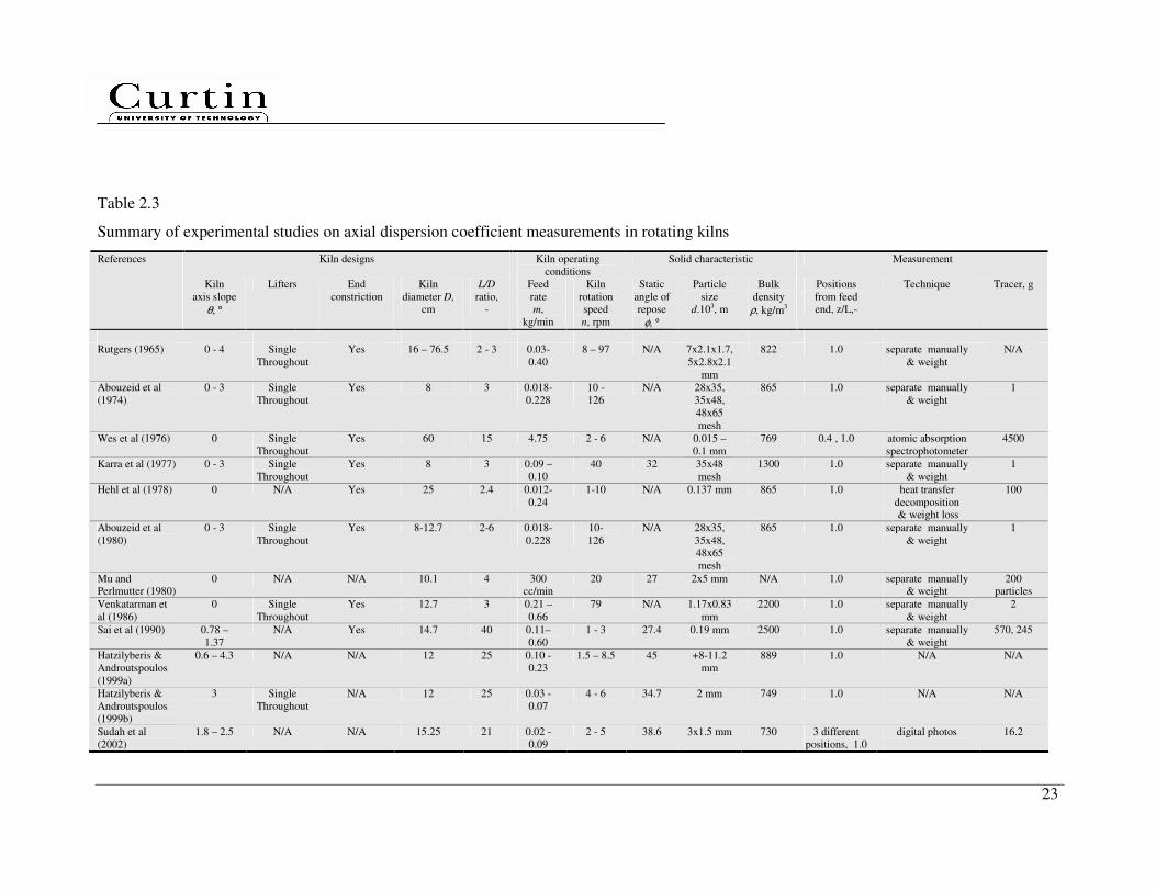
(1965-2002) were carried out to measure axial dispersion coefficient (Table 2.3) in
rotating kilns with or without lifters and end restrictions. Table 2.3 lists the key
studies which are relevant to this topic and provided sufficient process details. The
devices in all studies were operated at room temperature under steady state
conditions without freeboard gas. A wide-range of dry free-flowing granular solid
and powder was used, considering differences in particle size (0.015 mm – 11.2
mm), bulk density (730 kg/m3 - 2500 kg/m
3) and angle of repose (27° to 45°), but in
all cases the physical and chemical properties of solid were considered to be
unchanged when the solid passed through the kilns.
The kiln size varied from the laboratory- to pilot-scales; the minimum kiln diameter
studied was 0.08 m and the maximum 0.765 m, and the ratio of the kiln length to
diameter was between 2 and 40. The devices were operated at total kiln volumetric
filling fractions of 0.85 - 51 %, the rotational Froude number (8.22 x 10⁻⁵
– 8.46 x 10-
1). In most industrial applications, cascading motion is favourable because of its high
intensity of mixing. The slope of the kiln axis was small, lying between horizontal
and 4.3°.
15
All mixing experimental studies carried out the measurement of the RTD at the kiln
discharge end using a tracer technique (Levenspiel, 1999). The technique is a
stimulus/response technique method. It imposes an interference factor on the kiln
whilst it is in stationery operation and observing how this interference is broken
down inside it. While the kiln is operating in a steady-state, a fixed small amount of
dyed tracers was introduced without changing the flow pattern. This enables the
production of tracer concentrations were measured at the kiln’s outlet by collecting
the tracer/bulk mixture into cups. Samples were then collected until the entire tracer
has been discharged from the kiln. The tracers were manually separated from bulk
mixture and weighed to determine tracer concentrations. At end of the run the total
hold-up in the kiln was determined.
The RTD may also be determined using a non-intrusive image measurement
technique using a transparent rotating kiln (Sudah et al., 2002). This technique does
not disturb the structure of the mixture and allows a quantitative and evaluation of
local mixing degree in axial direction along the kiln. Image analysis allows
determining proportions of different colours at the entire exposed surface of the
mixing volume. Image analysis can be done off-line after picture taken within a
relatively short term of sampling. Previous study showed that the image analysis
technique is a powerful tool to characterise the mixing behaviour of the whole
mixture (Dauman and Nirschl, 2008).
The previous studies (Table 2.3) considered the effects of kiln rotational speed,
volumetric fill, feed rate, kiln axis slope, particle properties and dam height on the
axial-dispersion coefficient or Peclet number. For rotating kilns without lifters, the
RTD was found to consist of a narrow and approximately symmetric central peak.
The Peclet number was found to be high, indicating the granular flow being close to
plug flow behaviour of a pipe reactor. To obtain higher axial mixing coefficient or
lower Peclet number corresponds to wide and asymmetric RTD, short kiln length
(L/D ≈ 2-5), high kiln rotational speed (high Froude number) , low volumetric fill,
inclined kiln position and lifters, should be considered.
16
It was also found that the dispersion coefficient was weakly independent on feed rate
and end constriction. However, the coefficient was strongly dependent on the particle
properties, i.e size, shape, angle of repose and density. Increasing the particle
diameter increases the dispersion coefficient. Long particles give lower coefficients
than spherical particles and those wet-sticky particles give lower coefficients than
dry free-flowing granules (Rutgers, 1965). The dispersion number was strongly
dependent on the type of tracer in terms of its angle of repose, density and size (Sai
et al., 1990).
Values of axial-dispersion coefficients range from 7.02 x 10⁻⁷
to 2.61 x 10⁻⁵
m2/s
(corresponding to Pe between 71 and 3788) for kilns without lifters and 7.37 x 10⁻⁷
to
1.23 x 10⁻⁴
m2/s (corresponding to Pe between 13 and 388) for kilns with lifters. Wes
et al. (1976) found that the axial mixing coefficient is strongly affected by the
quantity of solid moving with the lifter, the orientation and number of the lifters.
Venkataraman et al. (1986) reported that the degree of mixing in the kiln fitted with
forward-spiralling square lifters was considerably greater than that in the kiln with
reverse-spiralling square lifters. The steady-state total hold-up in the kiln fitted with
the forward-spiralling square lifters was less than that in the kiln fitted with reverse-
spiralling square lifters. The solid transport in a kiln with the conventional bar lifters
(50 < Pe < 110) behaved more towards plug flow when compared with that of the
kiln fitted with these spiralling lifters (30 < Pe < 60), over the same range of feed
rates.
2.3 Heat Transfer
There are some unique challenges associated with the heat transfer in rotary kilns.
Typically, the kiln is inclined at a slight angle to the horizontal direction and the
solid bed is at an angle to the kiln due to rotation. Two distinct regions are present in
the cross-section of the kiln, i.e. the freeboard and the solid bed. The gases flow in
the freeboard while the solid material occupies the bed. The bed moves, but not in as
17
well-defined a manner as a liquid or a gas. The bed is constantly tumbled and mixed
by the kiln rotation and is continuously being exposed to the heat sources, i.e. under
the bed, on top of the bed, flame (for direct-fired kilns) and also rotating kiln wall.
Depending on applications, gases may evolve from the bed, which can be an
additional source of energy. Materials processing may also be exothermic or
endothermic depending on the involved chemical reactions (Martins et al., 2001;
Ortiz et al., 2005; Patisson et al., 2000; Ramakrishna et al., 1999). Some processes
may involve three-phase if the solid feed material melts and becomes liquid in the
kilns, in addition to the combustion gases and possible gases evolving from the
process.
2.3.1 Modelling
Over the last 40 years, there has been a continued interest in the modelling work on
axial heat transfer typically considered under steady state conditions. Zonal models
of heat transfer, where the kiln is divided into isoheat transfer slices, become
standard in heat transfer modelling of rotary kilns. The heat transfer component of
the one-dimensional models can be divided the slice into separated control volumes
of freeboard and bed.
Sass (1967) proposed one of the first early representations of one-dimensional
modelling of a directly heated rotary kiln without lifters. The model of Sass (1967)
formed the basis for the various subsequent models in the literatures for: (1) directly
heated rotary kilns without lifters (Barr et al., 1989; Brimacombe & Watkinson,
1978; Davis, 1996; Davis & Englund, 2003; Georgallis et al., 2005; Ghoshdastidar et
al., 2002; Klose & Wiest , 1999; Kroger et al., 1979; Li et al., 2005; Marias, 2003;
Mitchell et al., 2002; Mujumdar & Ranade, 2006; Mujumdar et al., 2006, 2007;
Palmer & Howes, 1998; Sammouda et al., 1999; Watkinson & Brimacombe, 1978,
1982; Wild, 1994) and with lifters (Kamke et al., 1986; Riquelme et al., 1991); and
(2) indirectly heated rotary kiln without lifters (Marias et al., 2005) and with lifters
(Wes et al., 1976).

18
Those models are capable of predicting average local compositions within the bed
and freeboard; and temperatures within the bed, kiln wall and freeboard as function
of axial position. Axial transport of solid in the kiln was considered to simulate total
volumetric filling fraction, solid residence time, variation in height of the bed, axial
velocity and the heat transfer area of exposed bed. However, axial mixing was
neglected for both rotary kilns.
The conditions in the freeboard and bed were each assumed to be well mixed hence
uniform in the transverse plane, yielding ordinary differential equations relating axial
gradients of temperature and composition to the net rates of heat transfer for each
control volume. It is also assumed that no net energy accumulation can occur within
the wall. The system of equations are therefore simultaneously for successive axial
positions.
Heat transfer inside rotary kilns occurs via conduction, convection and radiation.
The heat transfer modes can be divided into heat transfer outside, inside and across
the kiln wall. Each mode may involve one or more heat transfer mechanisms. In
general, radiative transfer is dominant at > 1000°C (Barr et al., 1989; Gorog et al.,
1981, 1982). The relative importance of each mode depends on the solid, gas and
kiln wall thermo-physical properties; kiln designs and kiln operating conditions.
The heat transfer outer, inner and across kiln wall includes mainly
1. the convection and radiation heat transfer from the flue gases to the kiln wall for
an indirectly heated rotary kiln or from the kiln wall to the ambient for a directly
heated rotary kiln,
2. the conduction and radiation heat transfer between the covered wall and the
covered bed,
3. the convection and radiation heat transfer between the exposed wall and the
freeboard gas,
4. the convection and radiation heat transfer between the freeboard gas and the
exposed bed,
19
5. the radiation heat transfer between exposed wall to exposed bed,
6. the convection and radiation heat transfer between the freeboard gas to the falling
particles for a rotary kiln with lifters, and
7. the conduction heat transfer from the outer kiln wall to the inner kiln wall for an
indirectly heated rotary kiln and visa versa for a directly heated rotary kiln.
For direct heating operations without lifters at temperatures up to 873°C, Ding et al.
(2001) indicated that heat transfer from the covered wall to the covered bed is the
dominant mechanism in supplying heat to the bed. Heat transfer between the
freeboard gas and the exposed bed accounts for only a small portion. The heat
transfer rate between the freeboard gas and the exposed wall may be comparable to
that between the covered wall and the covered bed indicating that both steps could be
controlling. Li et al. (2005) reported that heat transfer from covered wall to covered
bed and convection heat transfer from freeboard gas to exposed bed play a crucial
role in the fast heating of solid at the kiln inlet (up to 700°K). Gorog et al. (1982)
stated that in the high temperature regions of kiln (>1200°K), 60 to 80 % of the heat
received by the solid results from their radiative interaction with the freeboard gas
and exposed wall. With the low temperature regions of the kiln (< 1200°K), 70 % of
heat received by the solid results from the combination of freeboard convection and
the regenerative heating of the wall. Tscheng and Watkinson (1979) and Barr et al.
(1989) indicated that the heat transfer coefficients between the freeboard gas and
exposed bed are in the order of five to ten times the values between the gas and the
exposed wall.
Except the convection heat transfer from the flue gases to the outer kiln wall, reliable
correlations are available in the literature to determine heat transfer coefficients
related to each mode at <1273°K:
1. the convection heat transfer from the outer kiln wall to the ambient (Churchill &
Chu, 1975),
2. heat transfer between the covered wall and the covered bed accounting for
conduction and advection using penetration theory (Ferron & Singh, 1991;
Lehmberg et al., 1977; Li et al., 2005; Lybaert, 1987; Tscheng & Watkinson,
1979; Wes et al., 1976; Wachters & Kramers, 1964),
20
3. convection heat transfer between the freeboard gas and the exposed wall
(Tscheng & Watkinson, 1979),
4. convection heat transfer between the freeboard gas and the exposed bed (Tscheng
& Watkinson, 1979) and
5. convection heat transfer between the freeboard gas and the falling particles
(Churchill, 1983; Hirosue & Shinohara, 1976a, 1976b; Hirosue, 1989; Hirosue &
Mujumdar, 1993; Ranz & Marshall, 1952a, 1952b; Whitaker, 1972).
2.3.2 Experimental
Experimental studies can best be utilized for verification and enhancing the
reliability of the derived models. The common basis for the previous experimental
studies is the measurement of a set of axial gas, solid and kiln wall temperatures by
outfitting the kiln heavily with thermocouples. However, few experimental studies
(1976-2008) have been undertaken on axial heat transfer in rotary kilns with or
without lifters and end restrictions, due to the difficulty of making measurements on
a rotating vessel, particularly under industrial conditions.
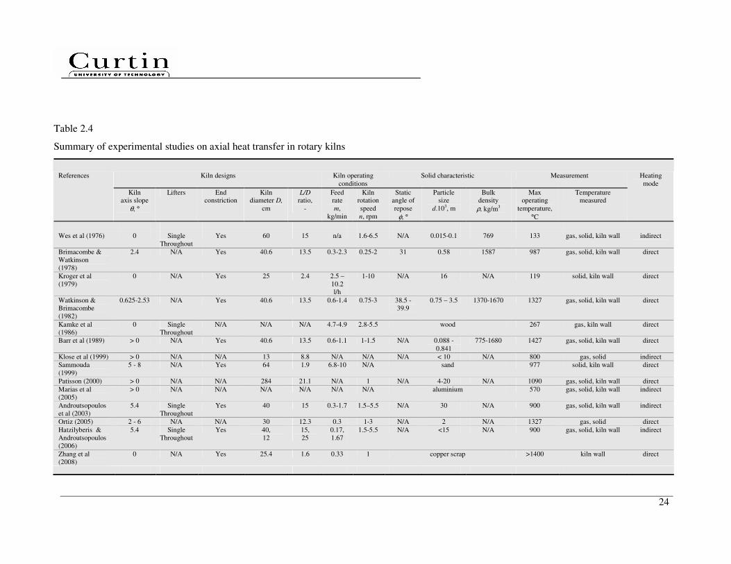
Table 2.4 summarises the key studies which are relevant to this topic and provided
sufficient process details. The devices in all studies in Table 2.4 were operated under
steady state conditions. A wide-range of dry free-flowing granular solid and powder
were used, considering differences in particle size (0.015 mm – 30 mm) and bulk
density (769 kg/m3 – 1680 kg/m
3). The kiln size varied between the laboratory- and
industrial-scales; the minimum kiln diameter studied was 0.12 m and the maximum
2.84 m, and the ratio of the kiln length to diameter was between 1.6 and 25. The
devices were operated at total kiln volumetric filling fractions of 5 – 25 %. A wide
range of rotational Froude numbers of 2.84 x 10⁻⁵
– 2.84 x 10⁻²
was investigated,
resulting in cascading motion in the transverse plane of the granular bed, as
described by Mellmann (2001). The slope of the kiln axis was small, lying between
horizontal and 8°. Most kilns were built up with end restrictions; however, few kilns
studies considered lifters.
21
Table 2.1
Summary of experimental studies on axial bed depth measurements in rotating kilns with/without lifters and end restrictions
Kiln designs Kiln operating
conditions
Solid characteristic Axial bed depth References
Kiln
axis slope
θ, °
Lifters End
constriction
Kiln
diameter
D, m
L/D
ratio,
-
Feed
rate
m,
kg/min
Kiln
rotation
speed
n, rpm
Static
angle of
repose
φ, °
Particle
size
d.103, m
Bulk
density
ρ, kg/m3
Positions Profile
Sullivan et
al.
(1927)
1-6 N/A
N/A 0.15 14.2 0.04 –
0.45
2.5 34.4 0.72 1700 13 Incline
Chaterjee
et al.
(1983a,
1983b)
1-3 N/A
Yes/No 0.2-0.6 3.3-16 0.25 –
1.25
0.3 - 0.7 35 6 1600 8 Incline/flat
Sai et al.
(1990,
1992)
0.78-1.37 N/A
Yes/No 0.147 40 0.11 –
0.60
1 - 3 27.4 0.19 2500 6 Incline/flat
Lebas et
al.
(1995)
1 N/A
N/A 0.6 10 5.30 –
10.44
2 - 4 47,47 15 480, 750 31 Incline
Spurling
(2000)
1-2 N/A
Yes/No 0.0515 19.42 0.006 –
0.2
5.82 32 0.46 1600 37 Incline

22
Table 2.2
Summary of experimental studies on total hold-up measurements in rotating kilns
Kiln designs Kiln operating
conditions
Solid characteristic References
Kiln
axis slope
θ, °
Lifters End
constriction
Kiln
diameter
D, m
L/D
ratio,
-
Feed
rate
m,
kg/min
Kiln
rotation
speed
n, rpm
Static
angle of
repose
φ, °
Particle
size
d.103, m
Bulk
density
ρ,
kg/m3
Dimensionless
empirical
correlation
developed
Vahl and
Kingma
(1952)
0 N/A
N/A 0.11 5.91 0.16 –
1.94
9 - 41 33 0.6 1490 Yes
Kramers and
Croockewit
(1952)
0.5 – 3.2 N/A
N/A 0.197 9.04 0.14 –
2.36
2.40 –
14.28
40, 36 0.9, 1.0 560,
1480
No
Hogg et al.
(1974)
0 Single
Throughout
Yes 0.095 2.61 0.08 –
0.24
90 38 0.4 1460 No
Chaterjee et al.
(1983a, 1983b)
1 – 3 N/A Yes 0.2 – 0.6 3.3 – 16 0.25 –
1.25
0.3 – 0.7 35 6 1600 Yes
Afacan and
Masliyah
(1990)
0 Single
Throughout
N/A 0.192 5.47 0.38 –
1.82
4.77 –
91.93
36 2.0 1640 No
Li et al.
(2002a)
0.62 –
2.40
Single
Throughout
Yes 0.30 6.00 0.19 –
1.04
2 - 8 48.5 2.5 225 No
Pan et al.
(2006)
0 Single
Throughout
N/A 0.374 3.21 0.42 –
1.40
3 – 9 30 3.0 695 No
23
Table 2.3
Summary of experimental studies on axial dispersion coefficient measurements in rotating kilns
Kiln designs Kiln operating
conditions
Solid characteristic Measurement References
Kiln
axis slope
θ, °
Lifters End
constriction
Kiln
diameter D,
cm
L/D
ratio,
-
Feed
rate
m,
kg/min
Kiln
rotation
speed
n, rpm
Static
angle of
repose
φ, °
Particle
size
d.103, m
Bulk
density
ρ, kg/m3
Positions
from feed
end, z/L,-
Technique Tracer, g
Rutgers (1965) 0 - 4 Single
Throughout
Yes 16 – 76.5 2 - 3 0.03-
0.40
8 – 97 N/A 7x2.1x1.7,
5x2.8x2.1
mm
822 1.0 separate manually
& weight
N/A
Abouzeid et al
(1974)
0 - 3 Single
Throughout
Yes 8 3 0.018-
0.228
10 -
126
N/A 28x35,
35x48,
48x65
mesh
865 1.0 separate manually
& weight
1
Wes et al (1976) 0 Single
Throughout
Yes 60 15 4.75 2 - 6 N/A 0.015 –
0.1 mm
769 0.4 , 1.0 atomic absorption
spectrophotometer
4500
Karra et al (1977) 0 - 3 Single
Throughout
Yes 8 3 0.09 –
0.10
40 32 35x48
mesh
1300 1.0 separate manually
& weight
1
Hehl et al (1978) 0 N/A Yes 25 2.4 0.012-
0.24
1-10 N/A 0.137 mm 865 1.0 heat transfer
decomposition & weight loss
100
Abouzeid et al
(1980)
0 - 3 Single
Throughout
Yes 8-12.7 2-6 0.018-
0.228
10-
126
N/A 28x35,
35x48, 48x65
mesh
865 1.0 separate manually
& weight
1
Mu and Perlmutter (1980)
0 N/A N/A 10.1 4 300 cc/min
20 27
2x5 mm N/A 1.0 separate manually & weight
200 particles
Venkatarman et
al (1986)
0 Single
Throughout
Yes 12.7 3 0.21 –
0.66
79 N/A 1.17x0.83
mm
2200 1.0 separate manually
& weight
2
Sai et al (1990) 0.78 –
1.37
N/A Yes 14.7 40 0.11–
0.60
1 - 3 27.4 0.19 mm
2500 1.0 separate manually
& weight
570, 245
Hatzilyberis &
Androutspoulos
(1999a)
0.6 – 4.3 N/A N/A 12 25 0.10 -
0.23
1.5 – 8.5 45 +8-11.2
mm
889 1.0 N/A N/A
Hatzilyberis &
Androutspoulos
(1999b)
3 Single
Throughout
N/A 12 25 0.03 -
0.07
4 - 6 34.7 2 mm 749 1.0 N/A N/A
Sudah et al
(2002)
1.8 – 2.5 N/A N/A 15.25 21 0.02 -
0.09
2 - 5 38.6 3x1.5 mm 730 3 different
positions, 1.0
digital photos
16.2
24
Table 2.4
Summary of experimental studies on axial heat transfer in rotary kilns
Kiln designs Kiln operating
conditions Solid characteristic Measurement References
Kiln axis slope
θ, °
Lifters End constriction
Kiln diameter D,
cm
L/D
ratio,
-
Feed rate
m,
kg/min
Kiln rotation
speed
n, rpm
Static angle of
repose
φ, °
Particle size
d.103, m
Bulk density
ρ, kg/m3
Max operating
temperature,
°C
Temperature measured
Heating
mode
Wes et al (1976) 0 Single
Throughout
Yes 60 15 n/a 1.6-6.5 N/A 0.015-0.1 769 133 gas, solid, kiln wall indirect
Brimacombe &
Watkinson
(1978)
2.4 N/A Yes 40.6 13.5 0.3-2.3 0.25-2 31 0.58 1587 987 gas, solid, kiln wall direct
Kroger et al
(1979)
0 N/A Yes 25 2.4 2.5 –
10.2
l/h
1-10 N/A 16 N/A 119 solid, kiln wall direct
Watkinson & Brimacombe
(1982)
0.625-2.53 N/A Yes 40.6 13.5 0.6-1.4 0.75-3 38.5 - 39.9
0.75 – 3.5 1370-1670 1327 gas, solid, kiln wall direct
Kamke et al
(1986)
0 Single
Throughout
N/A N/A N/A 4.7-4.9 2.8-5.5 wood 267 gas, kiln wall direct
Barr et al (1989) > 0 N/A Yes 40.6 13.5 0.6-1.1 1-1.5 N/A 0.088 -
0.841
775-1680 1427 gas, solid, kiln wall direct
Klose et al (1999) > 0 N/A N/A 13 8.8 N/A N/A N/A < 10 N/A 800 gas, solid indirect
Sammouda
(1999)
5 - 8 N/A Yes 64 1.9 6.8-10 N/A sand 977 solid, kiln wall direct
Patisson (2000) > 0 N/A N/A 284 21.1 N/A 1 N/A 4-20 N/A 1090 gas, solid, kiln wall direct
Marias et al
(2005)
> 0 N/A N/A N/A N/A N/A N/A aluminium 570 gas, solid, kiln wall indirect
Androutsopoulos
et al (2003)
5.4 Single
Throughout
Yes 40 15 0.3-1.7 1.5–5.5 N/A 30 N/A 900 gas, solid, kiln wall indirect
Ortiz (2005) 2 - 6 N/A N/A 30 12.3 0.3 1-3 N/A 2 N/A 1327 gas, solid direct
Hatzilyberis &
Androutsopoulos
(2006)
5.4 Single
Throughout
Yes 40,
12
15,
25
0.17,
1.67
1.5-5.5 N/A <15 N/A 900 gas, solid, kiln wall indirect
Zhang et al
(2008)
0 N/A Yes 25.4 1.6 0.33 1 copper scrap >1400 kiln wall direct
25
2.4 Summary
Through a thorough review of the literature, it is clear that little work has been done so
far on the influences of the installed segmented lifters on solid transport, mixing and
heat transfer. Much of the past research work focused on experimental and modelling
studies in directly heated rotary kilns without lifters. Less attention was paid on
identifying the controlling steps of heat transfer. Solid transport and mixing are
accountable for the heat transfer rate inside the kiln tube, i.e. between freeboard gas and
exposed bed, covered wall and covered bed and; freeboard gas and falling particles.
These limiting rates directly affect the yield and efficiency of the process and are quite
commonly a bottleneck.
Most of the transport and mixing experiments were based on rotating kilns with single
throughout lifters parallel to the axis of the kilns using a specific granular solid. None of
the transport experiments studied the bed depths determined in rotating kilns with lifters.
The effects of segmented lifters on solid transport and mixing have not yet been
researched and not well understood while such understanding of this is essential to
optimising lifter designs and configurations for enhanced axial solid transport and
mixing.
Unlike a non-invasive experimental technique, most axial dispersion coefficients were
quantified by separating the tracers manually and weighting at the kiln discharge end.
This procedure is tedious when the sample size is big. Moreover, due to transport
experiments were carried out after mixing; the amount of tracers used in all mixing
experiments was kept constant at different volumetric fill.
Through literature review, it is clear that developing transport and mixing models are
essential to the development of a model for kiln design and scaling considering
applications, kiln designs and operating conditions. Dimensionless correlations are very
26
useful for industry scale-up purpose but such correlations must be validated by
experimental investigations. Previous mechanistic and semi-empirical transport models
are also likely specific to the solid, lifter and end constriction types used. However, the
required depth and quality of experimental data for model development is often difficult
to obtain. DEM simulation is an emerging simulation tool but no DEM simulation has
been done on horizontal rotating kilns with segmented lifters. Therefore, there is a strong
need to develop transport, mixing and heat transfer models for an indirectly heat rotary
kiln with segmented lifters. This requires a systematic investigated research program.
Based on the literature review and key research gaps identified, the specific objectives of
the present research are as follows:
• To study the effect of segmented lifter designs, lifter configurations and end
constriction on solid transport and mixing experimentally in horizontal kilns, aiming
to investigate the potential of the use of segmented lifter to enhance axial solid
transport and mixing under various solid, kilns designs and operating conditions.
• To perform a preliminary DEM simulation on solid transport, aiming with attempts
to provide further insight into the role of lifters in axial displacement and to develop
a solid transport model, considering any measurable key engineering parameters at
industry level.
• To develop dimensionless empirical transport and mixing correlations and criteria
considering all three (over-, design-, and underloading) regimes.
• To carry out experimental study using a hot kiln to measure the temperature profiles
in the solid bed, freeboard gas, inner kiln wall and flue gas, and use the obtained data
for the validation of heat transfer model subsequently developed.
• To develop an integrated steady state axial heat transfer model in a hot kiln with
segmented lifters incorporating the developed solid transport and mixing
correlations, suitable heat transfer modes and reaction rate model.
27
Chapter 3
Methodology
This chapter details the research methodology employed in this thesis in order to achieve
the objectives outlined in Chapter 2. As discussed in Chapter 2, there are several modes
of heat transfer involved in the indirectly heated horizontal rotary kiln. Solid transport
and mixing are expected to be the key factors influencing the heat transfer inside the
kiln. Therefore, a systematic research methodology has been deployed, as illustrated in
Figure 3.1, considers both experimental and modelling studies.
The experimental investigations include mainly two parts, pilot-scale cold kilns and hot
kiln experiments. Various carefully-selected solid materials were used in our
experimental program covering a wide-range of static angle of repose, size and bulk
density. Dimensional analysis was also performed and a systematic experimental
program was then carried out to quantitatively investigate solid transport and mixing,
considering various kiln designs, kiln operating conditions and solid physical properties.
The key variables measured include total hold-up, bed depth and tracer concentration.
The cold kilns were designed with several removable rotating windows for the image
sampling method and axial bed depth profile measurement. The hot kiln has been
retrofitted to incorporate a temperature logging system, enabling the measurement of the
temperature profiles of flue gas, inner kiln wall, bed and freeboard gas.
The mathematical modelling includes three aspects, a theoretical transport model, a set
of dimensionless empirical correlations and a steady state axial heat transfer model. A
preliminary DEM simulation on solid transport was also performed to provide further
insight the role of segmented lifters. A theoretical transport model has also been
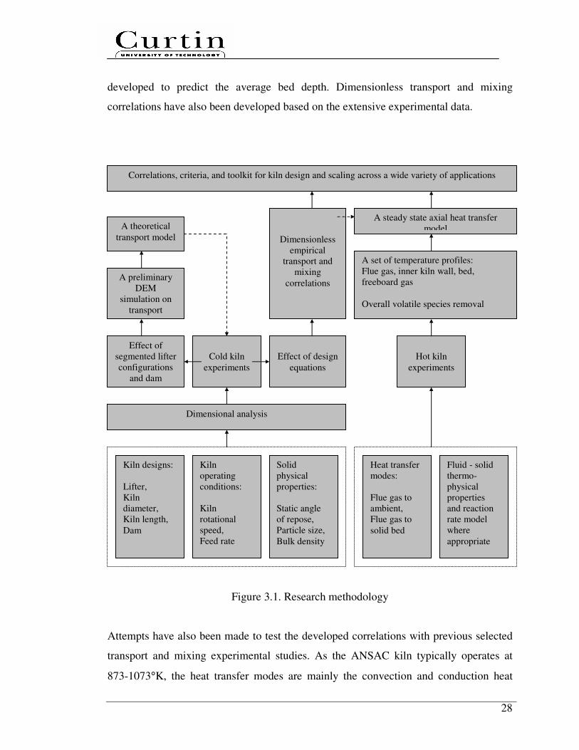
28
developed to predict the average bed depth. Dimensionless transport and mixing
correlations have also been developed based on the extensive experimental data.
Figure 3.1. Research methodology
Attempts have also been made to test the developed correlations with previous selected
transport and mixing experimental studies. As the ANSAC kiln typically operates at
873-1073°K, the heat transfer modes are mainly the convection and conduction heat
Cold kiln
experiments
Hot kiln
experiments
Effect of
segmented lifter
configurations
and dam
Dimensionless
empirical
transport and
mixing
correlations
Correlations, criteria, and toolkit for kiln design and scaling across a wide variety of applications
A set of temperature profiles:
Flue gas, inner kiln wall, bed,
freeboard gas
Overall volatile species removal
A steady state axial heat transfer model
A preliminary
DEM
simulation on
transport
A theoretical
transport model
Effect of design
equations
Dimensional analysis
Kiln designs:
Lifter,
Kiln
diameter,
Kiln length,
Dam
Kiln
operating
conditions:
Kiln
rotational
speed,
Feed rate
Solid
physical
properties:
Static angle
of repose,
Particle size,
Bulk density
Heat transfer
modes:
Flue gas to
ambient,
Flue gas to
solid bed
Fluid - solid
thermo-
physical
properties
and reaction
rate model
where
appropriate

29
transfers. The input data necessary for the model were obtained by own experiments or
from the literature. The model predictions were also compared with experimental data
for validation.
3.1 Dimensional analysis
Dimensional analysis can provide important guidance in experimental design, similarity
laws and data correlation. Compared to similitude based on governing differential
equations in batch mode, which resulted in 19 controlling dimensionless groups (Ding et
al., 2001), dimensional analysis is a simple, straightforward and powerful approach to
developed useful correlations for applications. The use of dimensional analysis requires
only knowledge of the variables that influence the phenomena of interest. The previous
experimental studies (Table 2.1, 2.2, 2.3) are very useful in compiling a set of
measurable key engineering parameters involved in the solid transport and mixing. The
objective is to determine an appropriate reduced set of dimensionless forms of these
dimensional variables. Such dimensionless terms can then be used in place of the
original individual variables and parameters to completely define the system behaviour
using conservation law of dimensions.
3.2 Granular solids
A wide range of dry monosize granular solid were carefully selected and tested. The set
of measurements was repeated five times and the characteristics of these granular solid
are listed in Table 3.1, 3.2 and 3.3. The static angle of repose, which is sensitive to shape
and roughness, was measured by a vertical quasi-two-dimensional Hele-Shaw cell
(SEED, n.d.).
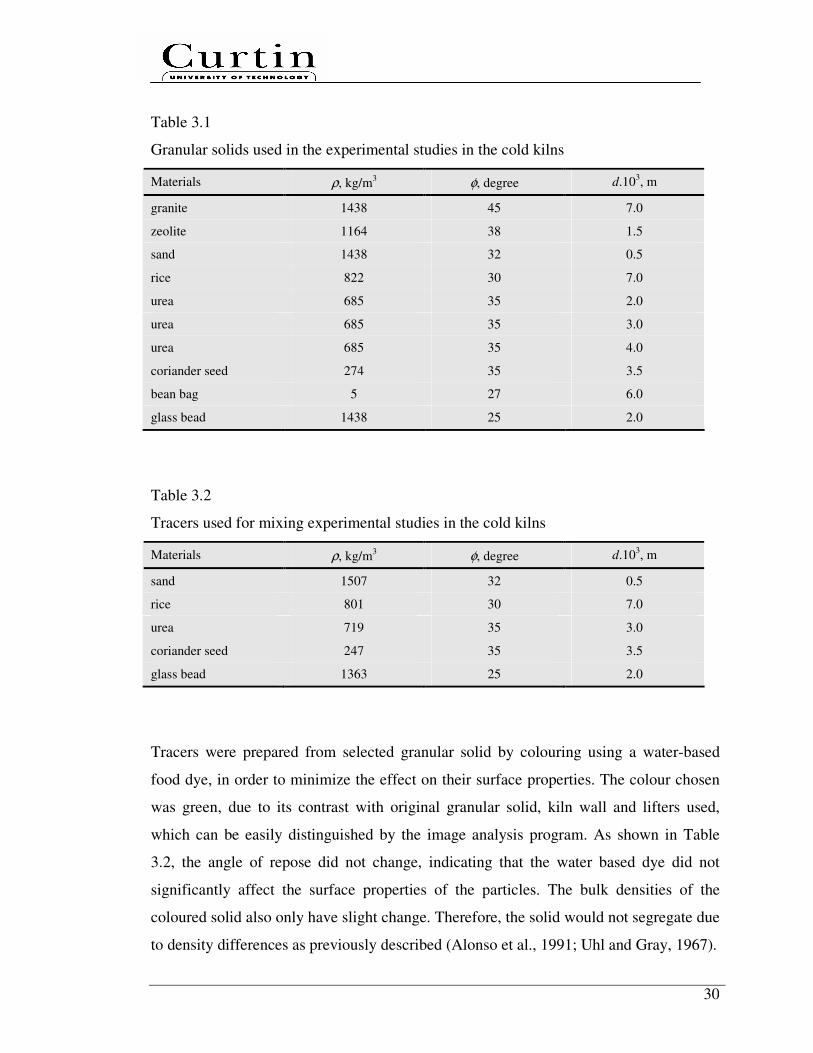
30
Table 3.1
Granular solids used in the experimental studies in the cold kilns
Materials ρ, kg/m3 φ, degree d.10
3, m
granite 1438 45 7.0
zeolite 1164 38 1.5
sand 1438 32 0.5
rice 822 30 7.0
urea 685 35 2.0
urea 685 35 3.0
urea 685 35 4.0
coriander seed 274 35 3.5
bean bag 5 27 6.0
glass bead 1438 25 2.0
Table 3.2
Tracers used for mixing experimental studies in the cold kilns
Materials ρ, kg/m3 φ, degree d.10
3, m
sand 1507 32 0.5
rice 801 30 7.0
urea 719 35 3.0
coriander seed 247 35 3.5
glass bead 1363 25 2.0
Tracers were prepared from selected granular solid by colouring using a water-based
food dye, in order to minimize the effect on their surface properties. The colour chosen
was green, due to its contrast with original granular solid, kiln wall and lifters used,
which can be easily distinguished by the image analysis program. As shown in Table
3.2, the angle of repose did not change, indicating that the water based dye did not
significantly affect the surface properties of the particles. The bulk densities of the
coloured solid also only have slight change. Therefore, the solid would not segregate due
to density differences as previously described (Alonso et al., 1991; Uhl and Gray, 1967).
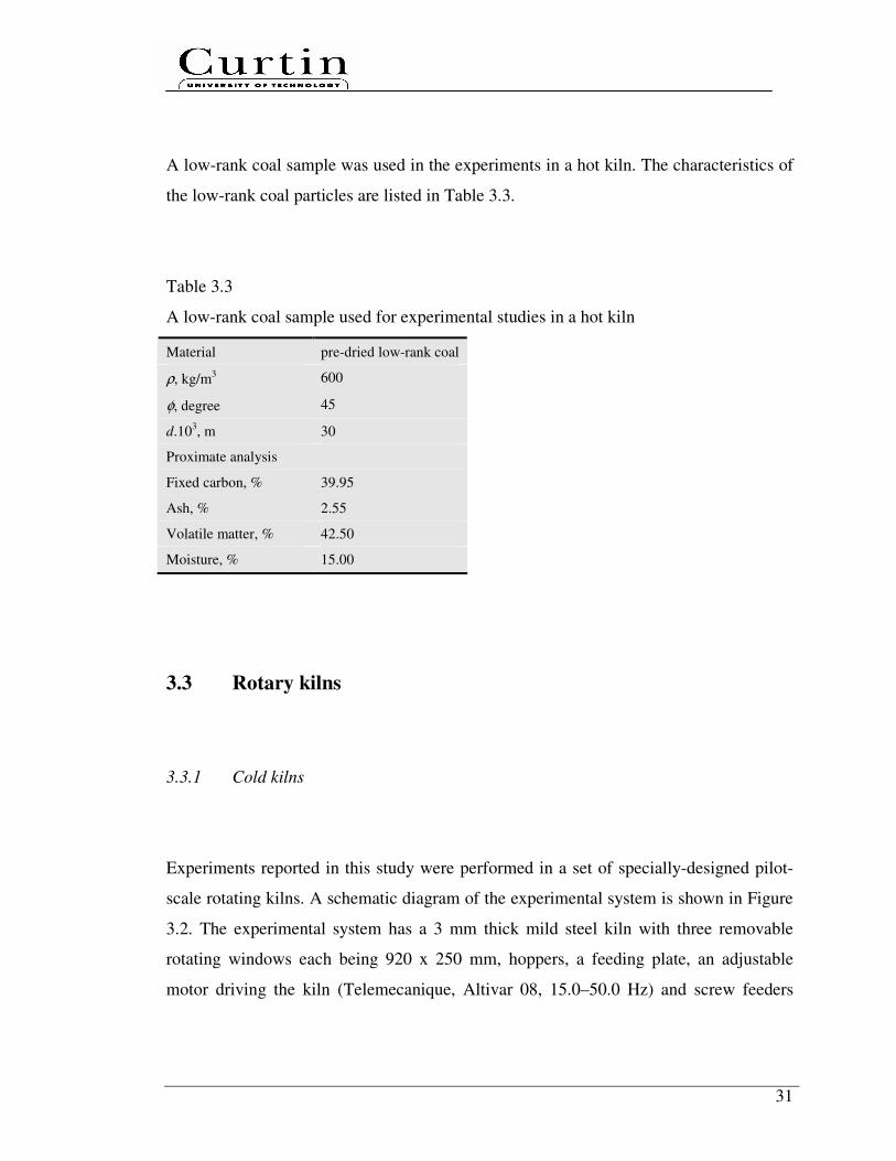
31
A low-rank coal sample was used in the experiments in a hot kiln. The characteristics of
the low-rank coal particles are listed in Table 3.3.
Table 3.3
A low-rank coal sample used for experimental studies in a hot kiln
Material pre-dried low-rank coal
ρ, kg/m3 600
φ, degree 45
d.103, m 30
Proximate analysis
Fixed carbon, % 39.95
Ash, % 2.55
Volatile matter, % 42.50
Moisture, % 15.00
3.3 Rotary kilns
3.3.1 Cold kilns
Experiments reported in this study were performed in a set of specially-designed pilot-
scale rotating kilns. A schematic diagram of the experimental system is shown in Figure
3.2. The experimental system has a 3 mm thick mild steel kiln with three removable
rotating windows each being 920 x 250 mm, hoppers, a feeding plate, an adjustable
motor driving the kiln (Telemecanique, Altivar 08, 15.0–50.0 Hz) and screw feeders

32
(Telemecanique, Altivar 31, 0–50.0 Hz). The last two devices were calibrated versus
kiln rotational speed and feed rate for each solid.
Figure 3.2. A schematic diagram of the cold-kiln experimental system: (a) hoppers, (b)
feeding plate, (c) fix end constriction (d) rotary kiln, (e) removable windows (a total of
3, arranged in series), (f) screw feeders, (g) removable lifters and (h) house jack
The rotating kiln is made up of a supporting frame equipped with a house jack
mechanism provided at the kiln feed and discharge ends which capable of adjusting the
axis kiln slope. The system can be checked, measured and adjusted using a SmartToolTM
digital spirit level, 1200 mm level with an accuracy of 0.1°. The kiln movement is
supported on four metal rollers.
This study employs three different kilns with diameters D and lengths L (D x L: 0.618 x
3.0, 0.510 x 3.6 and 0.400 x 4.0 m) which give L/D ratios of 5, 7 and 10. Fixed feed end
constrictions of height 0.20, 0.15 and 0.10 m from the kiln wall were used. The feed end
constrictions are to prevent back-spillage of the feed, through which a feeding plate
could be inserted into the rotating kiln.
Outflow of solid at the kiln discharge end was directed into a 20 L collection plastic
bucket. The bucket stands on top of a Mettler TE30 digital platform balance which has a
maximum load of 30 kg and an accuracy of 0.01 kg.
a
b d
g
f e
h
c
Y
X
Z
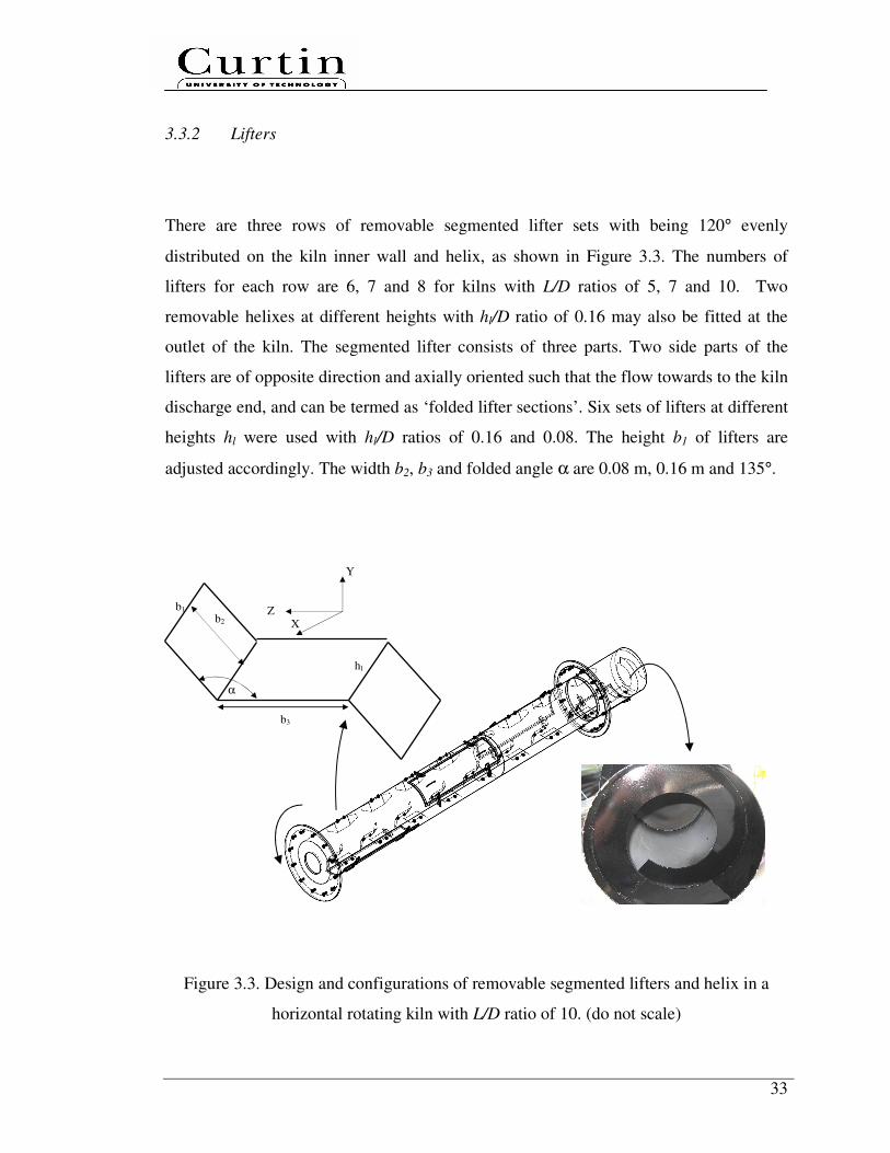
33
3.3.2 Lifters
There are three rows of removable segmented lifter sets with being 120° evenly
distributed on the kiln inner wall and helix, as shown in Figure 3.3. The numbers of
lifters for each row are 6, 7 and 8 for kilns with L/D ratios of 5, 7 and 10. Two
removable helixes at different heights with hl/D ratio of 0.16 may also be fitted at the
outlet of the kiln. The segmented lifter consists of three parts. Two side parts of the
lifters are of opposite direction and axially oriented such that the flow towards to the kiln
discharge end, and can be termed as ‘folded lifter sections’. Six sets of lifters at different
heights hl were used with hl/D ratios of 0.16 and 0.08. The height b1 of lifters are
adjusted accordingly. The width b2, b3 and folded angle α are 0.08 m, 0.16 m and 135°.
Figure 3.3. Design and configurations of removable segmented lifters and helix in a
horizontal rotating kiln with L/D ratio of 10. (do not scale)
Y
X Z
α
b1
hl
b2
b3
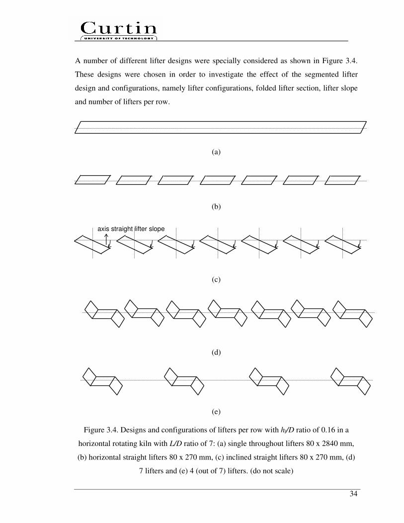
34
A number of different lifter designs were specially considered as shown in Figure 3.4.
These designs were chosen in order to investigate the effect of the segmented lifter
design and configurations, namely lifter configurations, folded lifter section, lifter slope
and number of lifters per row.
(a)
(b)
(c)
(d)
(e)
Figure 3.4. Designs and configurations of lifters per row with hl/D ratio of 0.16 in a
horizontal rotating kiln with L/D ratio of 7: (a) single throughout lifters 80 x 2840 mm,
(b) horizontal straight lifters 80 x 270 mm, (c) inclined straight lifters 80 x 270 mm, (d)
7 lifters and (e) 4 (out of 7) lifters. (do not scale)
axis straight lifter slope
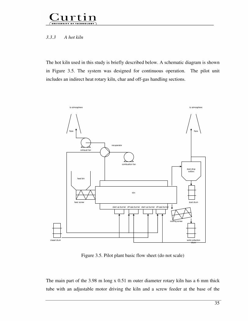
35
3.3.3 A hot kiln
The hot kiln used in this study is briefly described below. A schematic diagram is shown
in Figure 3.5. The system was designed for continuous operation. The pilot unit
includes an indirect heat rotary kiln, char and off-gas handling sections.
Figure 3.5. Pilot plant basic flow sheet (do not scale)
The main part of the 3.98 m long x 0.51 m outer diameter rotary kiln has a 6 mm thick
tube with an adjustable motor driving the kiln and a screw feeder at the base of the
diesel drum solid collection drum
dust drum
dust drop outbox
cooling screw
to atmosphere to atmosphere
flare flare
feed bin
kiln
start-up burner start-up burner off-gas burner off-gas burner
recuperator
combustion fan
exhaust fan
feed screw
36
hopper. The kiln case is lined with a 75 mm thick layer of insulating ceramic fiber. The
kiln has 21 segmented lifters (7 lifters per row, lifter height of 80 mm, spacing of 488
mm between all lifters), fix feed and discharge end (helix) constrictions. The heat tube is
a rotating tube driven from the discharge end by a gearbox and motor.
Material travels through the heat tube and was heated to a monitored and controlled
temperature of 800°C at the kiln inlet section and excess oxygen level at the exhaust
section by manipulating the amount of recycled off-gas and preheated air. The
temperature measurement is located on the outside skin surface of the heat tube. The
temperature of the material reaches approximately 873°K.
The solid product is collected in a jacketed cooling screw conveyor. This removes a
considerable amount of the heat in the material before it drops into a sealed 150 L
collection kiln which then stood on top of a digital platform balance. A slide-gate valve
mounted between the kiln and cooler was used to isolate the kiln when it requires
replacement. Operators move the kiln using a forklift and seal it, whilst replacing it with
an empty kiln.
The off-gas discharges out of the top of a disengagement chamber at the discharge end
of the kiln. The gas then proceeds through a dust drop out box. By allowing the velocity
of the gas to drop to very low speeds, dust particles settle in the chamber and into a kiln
below. If combustible, the off-gas from the dust drop out box may be recycled for heat
recovery.
Air to kiln burner is drawn in through a forced-draught fan. Combustion air is then
preheated by running counter-current through the shell-side of a shell and tube
recuperator mounted on the kiln combustion exhaust.
For characterization the various axial heat flows within the kiln and model validation
purposes, the pilot unit were also designed to measure 6 designated locations at a kiln

37
cross-section, as shown in Figure 3.6. The 3 mm diameter type-K shielded
thermocouples are directly mounted at 30 (6 x 5) designated locations and clustered into
three data takers. The five axial distances from the entrance of the kiln are 670 mm,
1530 mm, 2020 mm, 2570 mm and 3100 mm respectively. The first two designated
locations (1 and 2) are fixed to the kiln; the others (3, 4, 5 and 6) are attached to a
thermocouple holder and thus rotated with the kiln. The designated transverse location
no 2 is 5 mm from the outer wall. A stand alone and internal power data takers, DT80’s,
were used featuring USB memory stick support for data acquisition and logging.
(a) (b)
Figure 3.6. A pilot hot kiln showing the designated (a) transverse and (b) axial locations
of the thermocouples: (1) flue gas, (2) outer wall, (3) inner wall, (4) bed, (5) lifter and
(6) freeboard gas. (do not scale)
3.4 Image processing
The degree of axial dispersion along the kiln length was tracked by opening the
windows and taking digital photos of the surface tracers/bulk mixture each being 3648 x
• 2 •••• 1 • 6
• 5 •••• 4 •••• 3
Product Solid
•••• 1 •••• 1 •••• 1 •••• 1 •••• 1
• 2 • 2 • 2 • 2 • 2 •••• 3 •••• 3 •••• 3 •••• 3 •••• 3
• 5 • 5 • 5 • 5 • 5
•••• 4 •••• 4 •••• 4 •••• 4 •••• 4
• 6 • 6 • 6 • 6 • 6
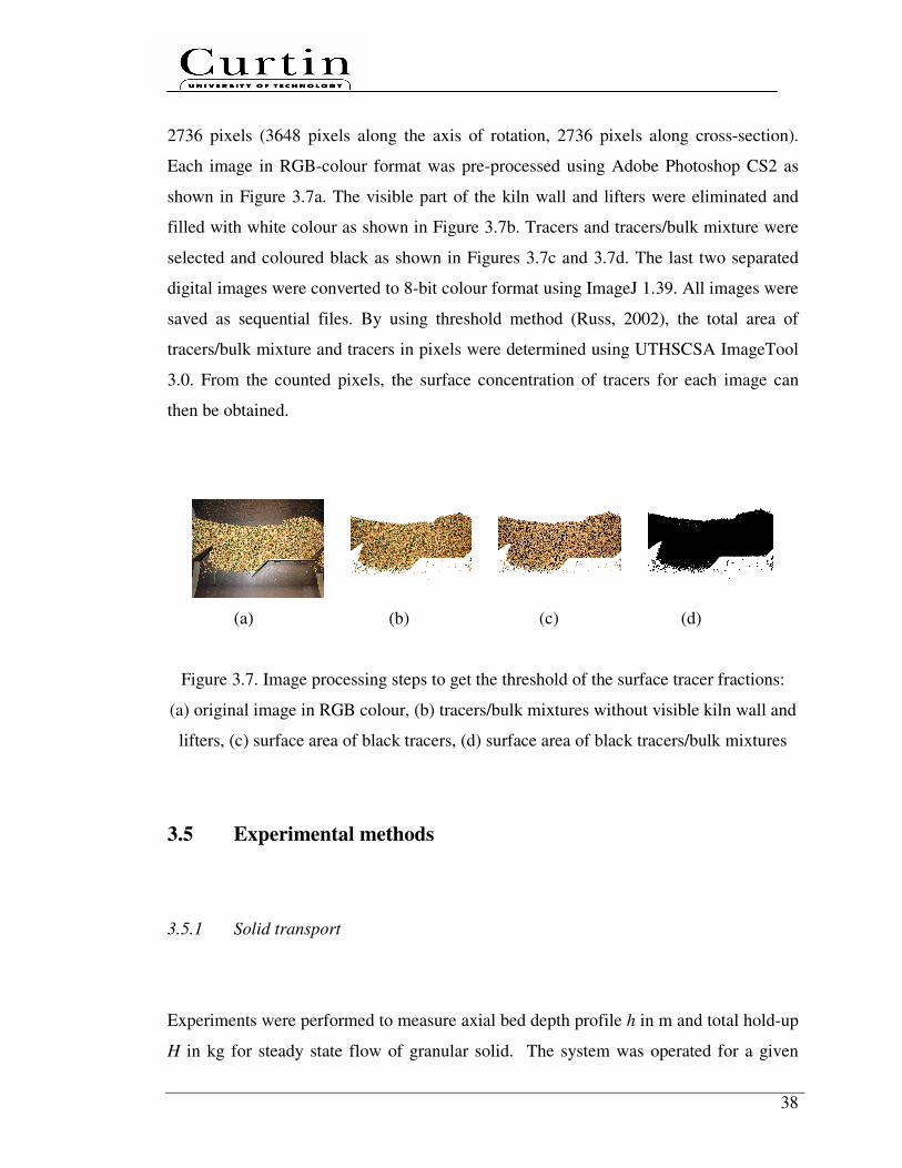
38
2736 pixels (3648 pixels along the axis of rotation, 2736 pixels along cross-section).
Each image in RGB-colour format was pre-processed using Adobe Photoshop CS2 as
shown in Figure 3.7a. The visible part of the kiln wall and lifters were eliminated and
filled with white colour as shown in Figure 3.7b. Tracers and tracers/bulk mixture were
selected and coloured black as shown in Figures 3.7c and 3.7d. The last two separated
digital images were converted to 8-bit colour format using ImageJ 1.39. All images were
saved as sequential files. By using threshold method (Russ, 2002), the total area of
tracers/bulk mixture and tracers in pixels were determined using UTHSCSA ImageTool
3.0. From the counted pixels, the surface concentration of tracers for each image can
then be obtained.
(a) (b) (c) (d)
Figure 3.7. Image processing steps to get the threshold of the surface tracer fractions:
(a) original image in RGB colour, (b) tracers/bulk mixtures without visible kiln wall and
lifters, (c) surface area of black tracers, (d) surface area of black tracers/bulk mixtures
3.5 Experimental methods
3.5.1 Solid transport
Experiments were performed to measure axial bed depth profile h in m and total hold-up
H in kg for steady state flow of granular solid. The system was operated for a given

39
solid, kiln designs and operating conditions at room-temperature and without freeboard
gas. The minimum Reω value was limited by total hold-up of ∼ 80 kg and total kiln
volumetric filling fraction of ∼20%. It was found the kiln rotational speed varies
between 1.16 and 3.88 rpm which corresponds to 15.0 to 50.0 Hz, giving Fr values from
3.01 x 10⁻⁴
to 5.21 x 10⁻³
. An independent set of experiments verified that the solid feed
rate at a given controller setting was constant and reproducible for each solid.
During the period prior to steady state being reached, the solid were recycled from the
discharge back to the feed hopper. This was done to ensure that the level of solid in the
feed hopper remained constant. After the system was at steady state when the discharge
rate is equal to the feed rate and no longer fluctuated with time, the kiln rotation and
screw feeder were then stopped simultaneously.
The bed depth at different axial kiln lengths was measured by opening the kiln windows
using a rod and pointer configurations similar to those in previous studies (Sai et al.,
1990, 1992; Chatterjee et al., 1983a, 1983b). Measurements were made in between
lifters at five distances of 640, 1060, 1905, 2345 and 2845 mm (L/D = 5), six distances
of 540, 1008, 1512, 1980, 2628 and 3060 mm (L/D = 7) and eight distances of 730,
1090, 1420, 1860, 2180, 2610, 3040, 3450 mm (L/D = 10) from the kiln feed end. The
bed depth within 540 mm from the kiln feed end was not considered due to feeding
plate. The axial solid velocity profile along the kiln was determined by dividing the
volumetric flow rate of solid by the cross-sectional area of the bed.
In order to measure the total hold-up, the solid in the kiln were discharged mechanically
and weighed. The mean residence time and average axial solid velocity can simply be
determined by τ = H / m and u = L /τ. It was verified that the experimental
measurements were reproducible by comparison of three independent sets of
measurements of the same steady state axial bed depth profile and total hold-up.
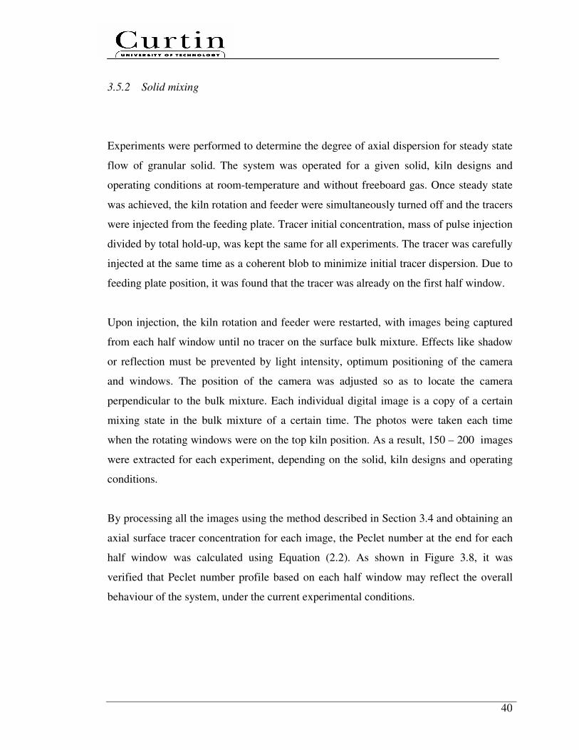
40
3.5.2 Solid mixing
Experiments were performed to determine the degree of axial dispersion for steady state
flow of granular solid. The system was operated for a given solid, kiln designs and
operating conditions at room-temperature and without freeboard gas. Once steady state
was achieved, the kiln rotation and feeder were simultaneously turned off and the tracers
were injected from the feeding plate. Tracer initial concentration, mass of pulse injection
divided by total hold-up, was kept the same for all experiments. The tracer was carefully
injected at the same time as a coherent blob to minimize initial tracer dispersion. Due to
feeding plate position, it was found that the tracer was already on the first half window.
Upon injection, the kiln rotation and feeder were restarted, with images being captured
from each half window until no tracer on the surface bulk mixture. Effects like shadow
or reflection must be prevented by light intensity, optimum positioning of the camera
and windows. The position of the camera was adjusted so as to locate the camera
perpendicular to the bulk mixture. Each individual digital image is a copy of a certain
mixing state in the bulk mixture of a certain time. The photos were taken each time
when the rotating windows were on the top kiln position. As a result, 150 – 200 images
were extracted for each experiment, depending on the solid, kiln designs and operating
conditions.
By processing all the images using the method described in Section 3.4 and obtaining an
axial surface tracer concentration for each image, the Peclet number at the end for each
half window was calculated using Equation (2.2). As shown in Figure 3.8, it was
verified that Peclet number profile based on each half window may reflect the overall
behaviour of the system, under the current experimental conditions.
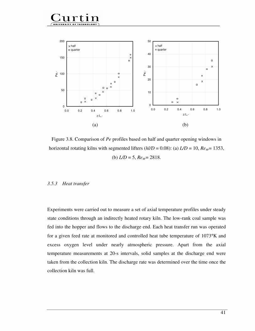
41
0
50
100
150
200
0.0 0.2 0.4 0.6 0.8 1.0
z/L,-
Pe,-
half
quarter
0
10
20
30
40
50
0.0 0.2 0.4 0.6 0.8 1.0
z/L,-
Pe,-
half
quarter
(a) (b)
Figure 3.8. Comparison of Pe profiles based on half and quarter opening windows in
horizontal rotating kilns with segmented lifters (hl/D = 0.08): (a) L/D = 10, Reω = 1353,
(b) L/D = 5, Reω = 2818.
3.5.3 Heat transfer
Experiments were carried out to measure a set of axial temperature profiles under steady
state conditions through an indirectly heated rotary kiln. The low-rank coal sample was
fed into the hopper and flows to the discharge end. Each heat transfer run was operated
for a given feed rate at monitored and controlled heat tube temperature of 1073°K and
excess oxygen level under nearly atmospheric pressure. Apart from the axial
temperature measurements at 20-s intervals, solid samples at the discharge end were
taken from the collection kiln. The discharge rate was determined over the time once the
collection kiln was full.
42
The kiln was started with diesel fuels The empty kiln was preheated with rotation for
two to three hours till the heat tube has reached greater than a setting typically 823°K
prior to commencing the feed.
All conditions were then maintained constant until all monitored variables stabilized. All
experimental results reported are based on the measured data during the steady-state
operations.
The obtained temperature profiles were used to determine the heat flux profiles, relative
distribution of various heat transfer modes along the kiln, the overall heat transfer
coefficients and heat transfer efficiency, considering all the heat transfer processes from
the flue gas to the bed. The importance of each of the heat transfer modes to the overall
heat transfer was then evaluated to determine the controlling steps of heat transfer.
3.6 Modelling
A part from experimental work, modelling work was also carried out to simulate solid
transport, mixing and heat transfer. To accomplish the mathematical solutions of the
models, the Polymath Version 5.1 was used. A preliminary DEM simulation, an
emerging simulation tool at particle level, using EDEM Version 1.3 was also performed
in a single 3.16 GHz processor mode of a E8500 – processor Intel(R) Core(TM) 2 Duo
CPU running 3.25 GB of RAM.
43
3.7 Summary
The chosen methodology to investigate the heat transfer mechanisms in an indirectly
heated rotary kiln with segmented lifters are described in this chapter. Systematic
investigation of the solid transport and mixing will provide crucial information for
developing the predictive tool of kiln design and scaling.
The utilisation of different techniques for cold and hot experiments enables the isolation
of the comprehensive analysis for both solid transport and mixing from heat transfer. A
combination of these techniques used in an innovative approach of the problem will
provide a better understanding of the overall heat transfer mechanisms.
44
Chapter 4
Solid Transport
In this chapter, dimensional analysis was performed and a systematic experimental
program was then carried out using the cold kilns under steady state condition to
quantitatively investigate the effect of segmented lifter configurations, helix and design
equations on solid transport. The study considers various kiln designs, kiln operating
conditions and solid physical properties. The key solid transport variables to be
measured were total hold-up and bed depth profile. The modelling and simulation work
include three parts: (1) a preliminary DEM simulation, (2) a theoretical transport model
and (3) dimensionless empirical correlations.
The solid, kiln design and operating condition parameters can affect the bulk solid
transport variables, namely total hold-up H in kg, mean residence time τ in s and axial
solid velocity u in m/s. These key solid transport variables are generally a function of
kiln design (kiln length L in m and kiln diameter D in m), kiln operating conditions (feed
rate m in kg/s, kiln rotational speed ω in rad/s), solid characteristics (mean particle size d
in m, particle bulk density ρ in kg/m3, particle static angle of repose φ in radian), the
acceleration of gravity g in m/s2 and lifter geometries (lifter height hl in m)
Based on Buckingham’s Π theorem (Munson et al., 2006), a dimensional analysis has
been carried out. The following applicable correlations are developed among a set of
dimensionless numbers:
45
2 2
12, , , , ,
/
lH
hH d L D DC
D L D D D g m D
ω ρωφ
ρ
= = Φ
,
Φ==
Dm
D
g
D
D
h
D
L
D
d
LD
mC l
22
22,,,,,
ρωωφ
ρ
ττ ,
Φ==
Dm
D
g
D
D
h
D
L
D
d
m
DuC l
u
22
3
2
,,,,,ρωω
φρ
.
The first three prediction equations are H/ρD2L, τm/ρD
2L and uρD
2/m, known as the
solid transport coefficients: CH, Cτ, and Cu. CH is a ratio between volumetric hold-up and
kiln volume. In practical applications, CH is generally replaced by total kiln volumetric
filling fraction f, with a simple conversion of f = CH × (4/π).
The six design equations are φ, d/D, L/D, hl/D, ω2D/g and ρωD
2/(m/D). The first and
second groups denote the solid characteristics. The third and fourth groups denote the
geometric ratio of the system. The fifth and sixth groups denote the dynamic ratio of the
system. The fifth group is Froude number Fr, ω2D/g or ω2
R/g, which is the ratio
between inertial and gravitational forces. The sixth group corresponds to the rotational
Reynolds number Reω, i.e. the ratio between inertial forces and the resistant forces which
the solid have to overcome.
The axial profile of velocity along the kiln ulocal in m/s is determined by dividing the
volumetric flow rate of solid Q in m3/s by the cross-sectional area of the bed Abed in m
2.
In a dimensionless form, ulocal is replaced by D2/Abed, known as the local solid transport
coefficient Cu,local in which Abed is a function of bed depth.
46
4.1 Effect of segmented lifter designs, lifter configurations and helix
on prediction equations and axial bed depth profile
In this section, a systematic experimental program was carried out using the cold kilns to
quantitatively investigate the presence (inclined kiln without lifters) and effect of
segmented lifter designs (folded lifter section and lifter slope), lifter configurations
(single throughout lifters, number of lifter per row) and helix on solid transport. All
experimental result plots are limited for glass bead and/or sand which are two extreme
cases.
4.1.1 Inclined kiln without lifters
All experimental studies dealt with solid transport through inclined rotating kilns
without lifters as shown in Table 2.1. However, design variables of rotating kilns and its
value as well as matrix combinations greatly vary between authors. In the present study,
the effect of the axis kiln slope on solid transport in a rotating kiln (L/D = 7) without
lifters was investigated and fairly compared with segmented lifters.
Figure 4.1 shows the impact of axis kiln slope without or with segmented lifters on solid
transport of sand under various Reω. The f in a horizontal kiln with segmented lifters is
lower than the ones without lifters at the same Reω (Figure 4.1a). The solid movement in
a kiln with segmented lifters is dominantly driven by physical push towards kiln
discharge end. As axis kiln slope increases from 0° to 0.5°, f decreases. This is
understandable because higher Reω translates into greater inertial forces (mainly due to
kiln rotational speeds) and leads to faster solid transport therefore lower f.
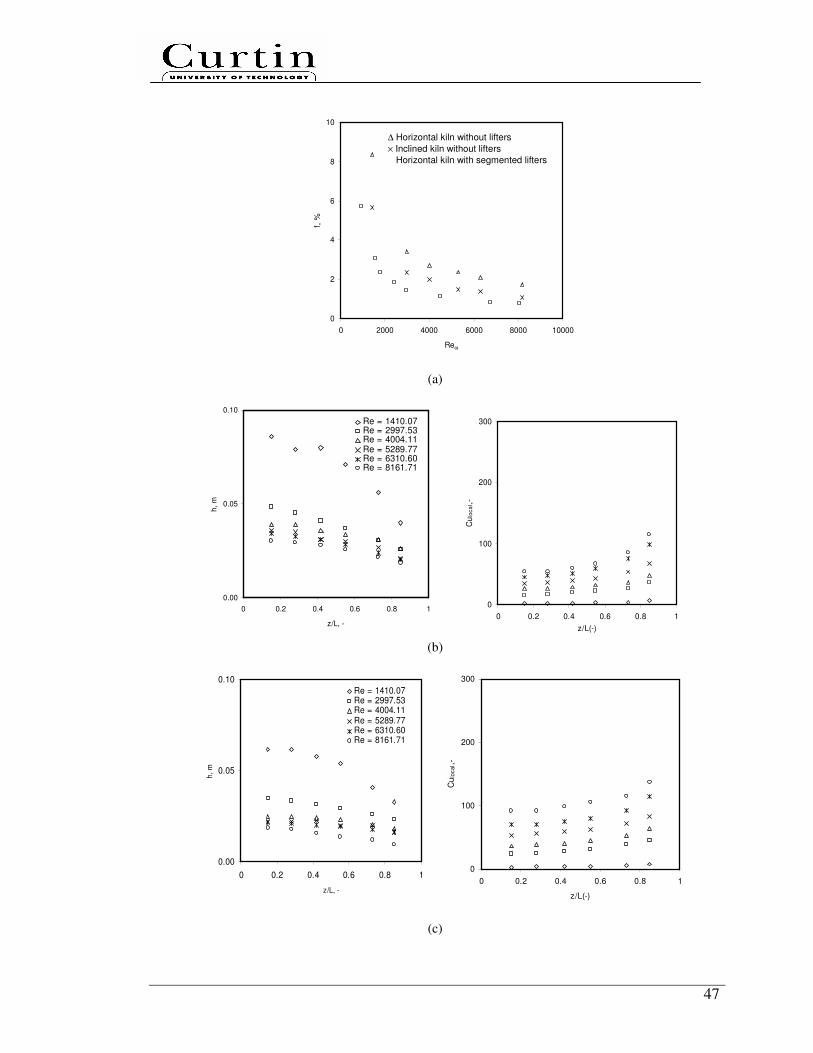
47
0
2
4
6
8
10
0 2000 4000 6000 8000 10000
Reω
f, %
(a)
0.00
0.05
0.10
0 0.2 0.4 0.6 0.8 1
z/L, -
h,
m
Re = 1410.07Re = 2997.53Re = 4004.11Re = 5289.77Re = 6310.60Re = 8161.71
0
100
200
300
0 0.2 0.4 0.6 0.8 1
z/L(-)
Cu
loc
al,-
(b)
0.00
0.05
0.10
0 0.2 0.4 0.6 0.8 1
z/L, -
h,
m
Re = 1410.07Re = 2997.53Re = 4004.11 Re = 5289.77Re = 6310.60Re = 8161.71
0
100
200
300
0 0.2 0.4 0.6 0.8 1
z/L(-)
Cu
loc
al,-
(c)
∆ Horizontal kiln without lifters
× Inclined kiln without lifters
� Horizontal kiln with segmented lifters

48
0
0.05
0.1
0 0.2 0.4 0.6 0.8 1
z/L, -
h, m
Re=927.24Re=1548.73Re=1798.52Re=2412.59Re=2965.56Re=8059.28
0
100
200
300
0 0.2 0.4 0.6 0.8 1
z/L, -
Cu
loc
al ,
-
Re=927.24
Re=1548.73
Re=1798.52
Re=2412.59
Re=2965.56
Re=8059.28
(d)
Figure 4.1. The f, h and Culocal of sand in a rotary kiln (L/D = 7) without and with
segmented lifters (hl/D = 0.16): (a) f vs Reω at different axis kiln slopes without and with
segmented lifters; h and Culocal vs z/L under various Reω in: (b) a horizontal kiln without
lifters, (c) an inclined kiln without lifters, (d) a horizontal kiln with segmented lifters
The bed depth profile increases with f. For kilns without lifters with inclined bed depth
profiles (Figures 4.1b and 4.1c), solid are transported faster in inclined kilns compared
to horizontal kilns. It is possible that the increasing axis kiln slope causes the increment
of the gravitational forces component in the axial direction of individual particle during
cascading. Governed by conservation theory, d(ρ.ulocal.Abed)/dz = 0, lower bed depth
corresponds to larger axial local velocity and smaller f, which finally causes a decrease
in residence time.
In case of a rolling mode in transversal bed motion, the axial transport of solid in kilns
without lifters mainly occurs in the thin active layer of bed surface follows the steepest
line of descent (Saeman, 1951). Within the passive layer (sub-surface), the bed is close
packed and the particles rotate with the kiln at fixed radius and axial position; this is
plug flow and particle interaction is limited. As Reω increases, particles entering the
active layer per unit time increase, which further results in the increase of the particle’s
axial displacement and the decrease of f.
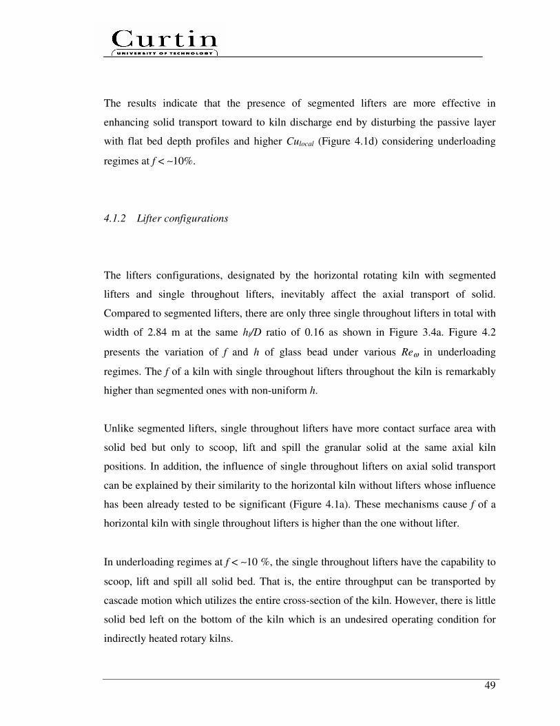
49
The results indicate that the presence of segmented lifters are more effective in
enhancing solid transport toward to kiln discharge end by disturbing the passive layer
with flat bed depth profiles and higher Culocal (Figure 4.1d) considering underloading
regimes at f < ∼10%.
4.1.2 Lifter configurations
The lifters configurations, designated by the horizontal rotating kiln with segmented
lifters and single throughout lifters, inevitably affect the axial transport of solid.
Compared to segmented lifters, there are only three single throughout lifters in total with
width of 2.84 m at the same hl/D ratio of 0.16 as shown in Figure 3.4a. Figure 4.2
presents the variation of f and h of glass bead under various Reω in underloading
regimes. The f of a kiln with single throughout lifters throughout the kiln is remarkably
higher than segmented ones with non-uniform h.
Unlike segmented lifters, single throughout lifters have more contact surface area with
solid bed but only to scoop, lift and spill the granular solid at the same axial kiln
positions. In addition, the influence of single throughout lifters on axial solid transport
can be explained by their similarity to the horizontal kiln without lifters whose influence
has been already tested to be significant (Figure 4.1a). These mechanisms cause f of a
horizontal kiln with single throughout lifters is higher than the one without lifter.
In underloading regimes at f < ∼10 %, the single throughout lifters have the capability to
scoop, lift and spill all solid bed. That is, the entire throughput can be transported by
cascade motion which utilizes the entire cross-section of the kiln. However, there is little
solid bed left on the bottom of the kiln which is an undesired operating condition for
indirectly heated rotary kilns.
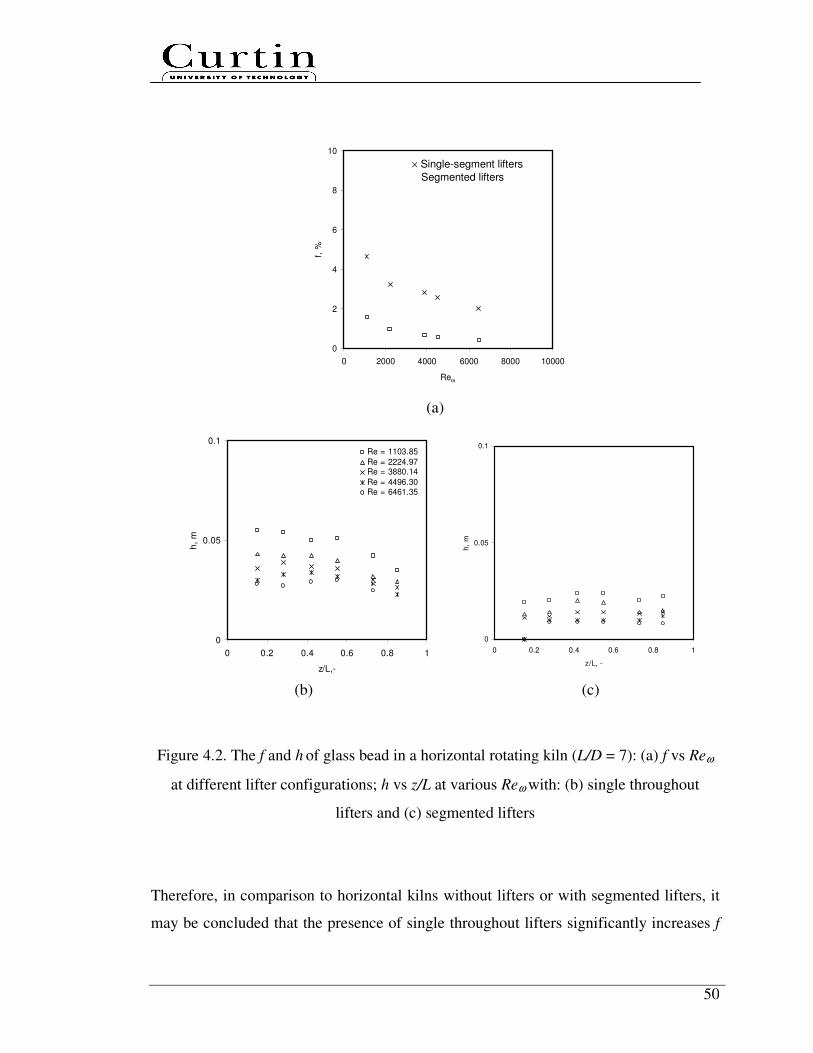
50
0
2
4
6
8
10
0 2000 4000 6000 8000 10000
Reω
f, %
(a)
0
0.05
0.1
0 0.2 0.4 0.6 0.8 1
z/L,-
h,
m
Re = 1103.85
Re = 2224.97Re = 3880.14
Re = 4496.30Re = 6461.35
0
0.05
0.1
0 0.2 0.4 0.6 0.8 1
z/L, -
h,
m
(b) (c)
Figure 4.2. The f and h of glass bead in a horizontal rotating kiln (L/D = 7): (a) f vs Reω
at different lifter configurations; h vs z/L at various Reω with: (b) single throughout
lifters and (c) segmented lifters
Therefore, in comparison to horizontal kilns without lifters or with segmented lifters, it
may be concluded that the presence of single throughout lifters significantly increases f
× Single-segment lifters
� Segmented lifters
51
of granular solid, which was observed in previous experimental studies (Afacan and
Masliyah, 1990; Hogg et al., 1974; Pan et al., 2006; Li et al., 2002a), leading to non-
uniform bed depth.
4.1.3 Folded lifter section
The impact of the segmented lifters without folded lifter sections, namely segmented
straight lifters, on axial granular solid transport in horizontal rotating kilns is shown in
Figure 4.3. In addition to width b3 of segmented lifter (Figure. 3.3), the segmented
straight lifters were extended by 0.055 m for each side to compensate the absence of the
folded lifter sections. At the same hl/D ratio of 0.16, the segmented straight lifters lead to
a higher f (Figure 4.3a) and non-uniform bed depth profiles (Figure 4.3b). With less
contact surface area, the influence of segmented straight lifters on axial granular solid
transport can be explained by their similarity to the single throughout lifters whose
influence has been already tested to be notable (Figure 4.2a).
0
2
4
6
8
10
0 2000 4000 6000 8000 10000
Reω
f, %
0
0.05
0.1
0 0.2 0.4 0.6 0.8 1
z/L,-
h,
m
Re = 1104Re = 2225Re = 3880Re = 4496Re = 6461
(a) (b)
Figure 4.3. The f and h of glass bead in a horizontal rotating kiln (L/D = 7): (a) f vs Reω
at different segmented lifters, (b) h vs z/L at various Reω with segmented straight lifters
× Segmented straight lifters
� Segmented lifters
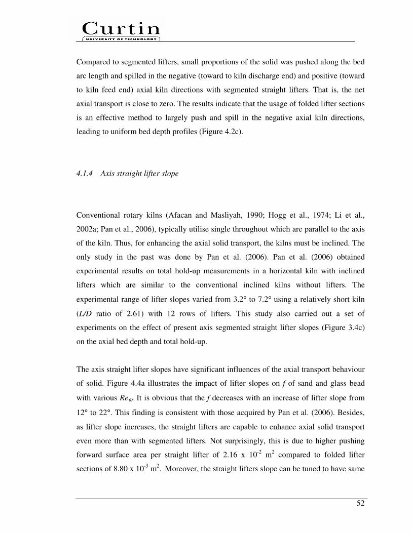
52
Compared to segmented lifters, small proportions of the solid was pushed along the bed
arc length and spilled in the negative (toward to kiln discharge end) and positive (toward
to kiln feed end) axial kiln directions with segmented straight lifters. That is, the net
axial transport is close to zero. The results indicate that the usage of folded lifter sections
is an effective method to largely push and spill in the negative axial kiln directions,
leading to uniform bed depth profiles (Figure 4.2c).
4.1.4 Axis straight lifter slope
Conventional rotary kilns (Afacan and Masliyah, 1990; Hogg et al., 1974; Li et al.,
2002a; Pan et al., 2006), typically utilise single throughout which are parallel to the axis
of the kiln. Thus, for enhancing the axial solid transport, the kilns must be inclined. The
only study in the past was done by Pan et al. (2006). Pan et al. (2006) obtained
experimental results on total hold-up measurements in a horizontal kiln with inclined
lifters which are similar to the conventional inclined kilns without lifters. The
experimental range of lifter slopes varied from 3.2° to 7.2° using a relatively short kiln
(L/D ratio of 2.61) with 12 rows of lifters. This study also carried out a set of
experiments on the effect of present axis segmented straight lifter slopes (Figure 3.4c)
on the axial bed depth and total hold-up.
The axis straight lifter slopes have significant influences of the axial transport behaviour
of solid. Figure 4.4a illustrates the impact of lifter slopes on f of sand and glass bead
with various Reω. It is obvious that the f decreases with an increase of lifter slope from
12° to 22°. This finding is consistent with those acquired by Pan et al. (2006). Besides,
as lifter slope increases, the straight lifters are capable to enhance axial solid transport
even more than with segmented lifters. Not surprisingly, this is due to higher pushing
forward surface area per straight lifter of 2.16 x 10⁻²
m2 compared to folded lifter
sections of 8.80 x 10⁻³
m2. Moreover, the straight lifters slope can be tuned to have same

53
f values in a kiln with or without segmented lifters within the range of cases considered
in this study.
However, the present experimental results show that the f values differences are smaller
at a higher lifter slope, especially from 15° to 22°. This suggests that at a higher lifter
slope, instead of push towards the kiln discharge end, the lifters start to hinder particles
entering and exiting the lifters. Therefore, it will cause an increase of f.
Unlike with segmented lifters in underloading regimes at f <∼ 10 %, the bed depth is
uniform only at critical lifter slope. The value of the critical lifter slope is dependent on
the granular solid characteristics. The comparisons of bed depth along the kiln under
various Reω at different lifter types for sand and glass bead are shown in Figures 4.4b
and 4.4c. The critical lifter slopes for both solid are slightly different. The critical lifter
slope is smaller for granular solid with lower φ and higher d, e.g. ∼ 12° for glass beads
and ∼ 15° for sand, respectively. In an extreme case with a lifter slope of 90°, a
segmented straight lifter can be regarded as an end restriction dam or one circular rib.
Literatures have shown that the influence on solid transport is significant (Chaterjee et
al., 1983a, 1983b; Li et al., 2002a; Sai et al., 1990, 1992; Spurling, 2000). Hence, for a
higher axial pushing effect toward to kiln discharge end, that is not worthwhile to
decrease folded angle α of 135° (Figure 3.3).
4.1.5 Number of lifters per row
Figure 4.5 demonstrates the dependence of f and h on the Reω considering segmented
lifters with two different lifter numbers per row, i.e. four and seven, in a horizontal
rotating kiln. This was achieved by simply taking off the second, fourth and sixth lifters
in each row as shown in Figure 3.4d and Figure 3.4e.

54
0
2
4
6
8
10
0 2000 4000 6000 8000 10000
Reω
f, %
0
2
4
6
8
10
0 2000 4000 6000 8000 10000
Reω
f, %
(a)
0
0.01
0.02
0.03
0.04
0.05
0 0.2 0.4 0.6 0.8 1
z/L,-
h,m
Re = 1103.85
Re = 2224.97
Re = 3880.14
Re = 4496.30
Re = 6461.35
0
0.01
0.02
0.03
0.04
0.05
0 0.2 0.4 0.6 0.8 1
z/L,-
h,m
Re = 2398.03
Re = 5168.16
Re = 8020.99
0
0.01
0.02
0.03
0.04
0.05
0 0.2 0.4 0.6 0.8 1
z/L,-
h,m
0
0.01
0.02
0.03
0.04
0.05
0 0.2 0.4 0.6 0.8 1
z/L,-
h,m
Glass bead + inclined kiln without lifters
� segmented lifters
∆ 12° straight lifter slope
× 15° straight lifter slope
ο 22° straight lifter slope
Sand + inclined kiln without lifters
� segmented lifters
∆ 12° straight lifter slope
× 15° straight lifter slope
ο 22° straight lifter slope
Glass bead
12° straight lifter slope
Glass bead
15° straight lifter slope
Sand
12° straight lifter slope
Sand
15° straight lifter slope

55
0
0.01
0.02
0.03
0.04
0.05
0 0.2 0.4 0.6 0.8 1
z/L,-
h,m
0
0.01
0.02
0.03
0.04
0.05
0 0.2 0.4 0.6 0.8 1
z/L,-
h,m
(b) (c)
Figure 4.4. The f and h of sand and glass bead in a horizontal rotating kiln (L/D = 7): (a)
f vs Reω at different lifter types; h vs z/L at various Reω and lifter slopes: (b) glass bead
and (c) sand.
0
2
4
6
8
10
12
0 2000 4000 6000 8000 10000
Reω
f, %
0
0.05
0.1
0 0.2 0.4 0.6 0.8 1
z/L, -
h,
m
Re=462.08
Re=1103.85
Re=2215.84Re=3906.42
Re=4521.42
Re=6489.07
(a) (b)
Figure 4.5. The f and h of glass bead in a horizontal rotating kiln (L/D = 7): (a) Reω vs f
at different segmented lifter numbers per row and (b) h vs z/L at various Reω with four
segmented lifters per row
Glass bead
22° straight lifter slope
Sand
22° straight lifter slope
× 4 segmented lifters per row
� 7 segmented lifters per row
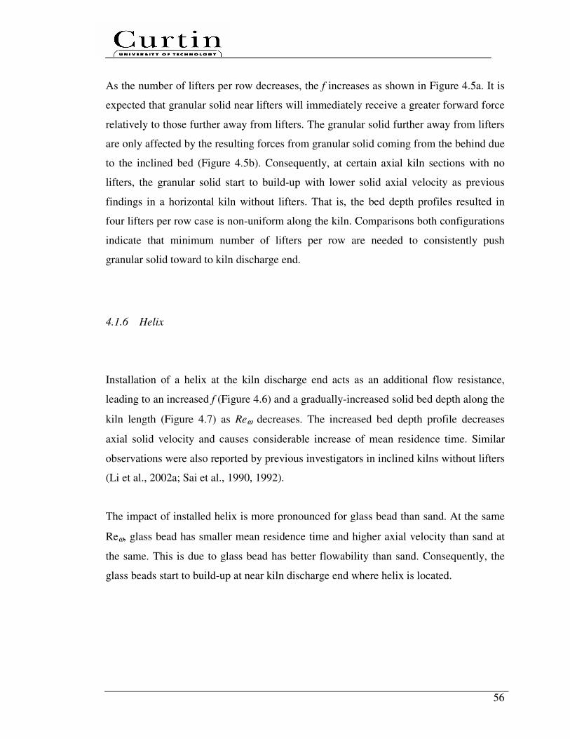
56
As the number of lifters per row decreases, the f increases as shown in Figure 4.5a. It is
expected that granular solid near lifters will immediately receive a greater forward force
relatively to those further away from lifters. The granular solid further away from lifters
are only affected by the resulting forces from granular solid coming from the behind due
to the inclined bed (Figure 4.5b). Consequently, at certain axial kiln sections with no
lifters, the granular solid start to build-up with lower solid axial velocity as previous
findings in a horizontal kiln without lifters. That is, the bed depth profiles resulted in
four lifters per row case is non-uniform along the kiln. Comparisons both configurations
indicate that minimum number of lifters per row are needed to consistently push
granular solid toward to kiln discharge end.
4.1.6 Helix
Installation of a helix at the kiln discharge end acts as an additional flow resistance,
leading to an increased f (Figure 4.6) and a gradually-increased solid bed depth along the
kiln length (Figure 4.7) as Reω decreases. The increased bed depth profile decreases
axial solid velocity and causes considerable increase of mean residence time. Similar
observations were also reported by previous investigators in inclined kilns without lifters
(Li et al., 2002a; Sai et al., 1990, 1992).
The impact of installed helix is more pronounced for glass bead than sand. At the same
Reω, glass bead has smaller mean residence time and higher axial velocity than sand at
the same. This is due to glass bead has better flowability than sand. Consequently, the
glass beads start to build-up at near kiln discharge end where helix is located.
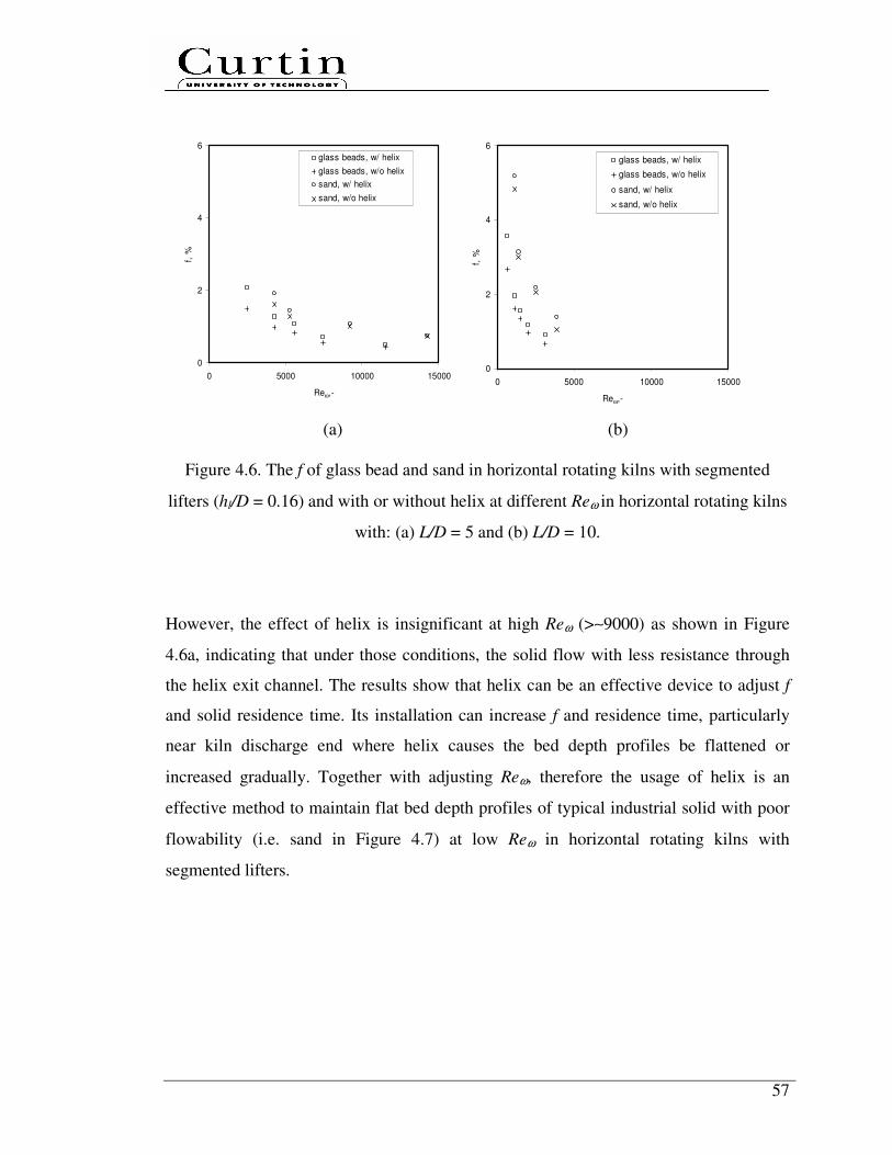
57
0
2
4
6
0 5000 10000 15000
Reω,-
f, %
glass beads, w/ helix
glass beads, w/o helix
sand, w/ helix
sand, w/o helix
0
2
4
6
0 5000 10000 15000
Reω,-
f, %
glass beads, w/ helix
glass beads, w/o helix
sand, w/ helix
sand, w/o helix
(a) (b)
Figure 4.6. The f of glass bead and sand in horizontal rotating kilns with segmented
lifters (hl/D = 0.16) and with or without helix at different Reω in horizontal rotating kilns
with: (a) L/D = 5 and (b) L/D = 10.
However, the effect of helix is insignificant at high Reω (>∼9000) as shown in Figure
4.6a, indicating that under those conditions, the solid flow with less resistance through
the helix exit channel. The results show that helix can be an effective device to adjust f
and solid residence time. Its installation can increase f and residence time, particularly
near kiln discharge end where helix causes the bed depth profiles be flattened or
increased gradually. Together with adjusting Reω, therefore the usage of helix is an
effective method to maintain flat bed depth profiles of typical industrial solid with poor
flowability (i.e. sand in Figure 4.7) at low Reω in horizontal rotating kilns with
segmented lifters.
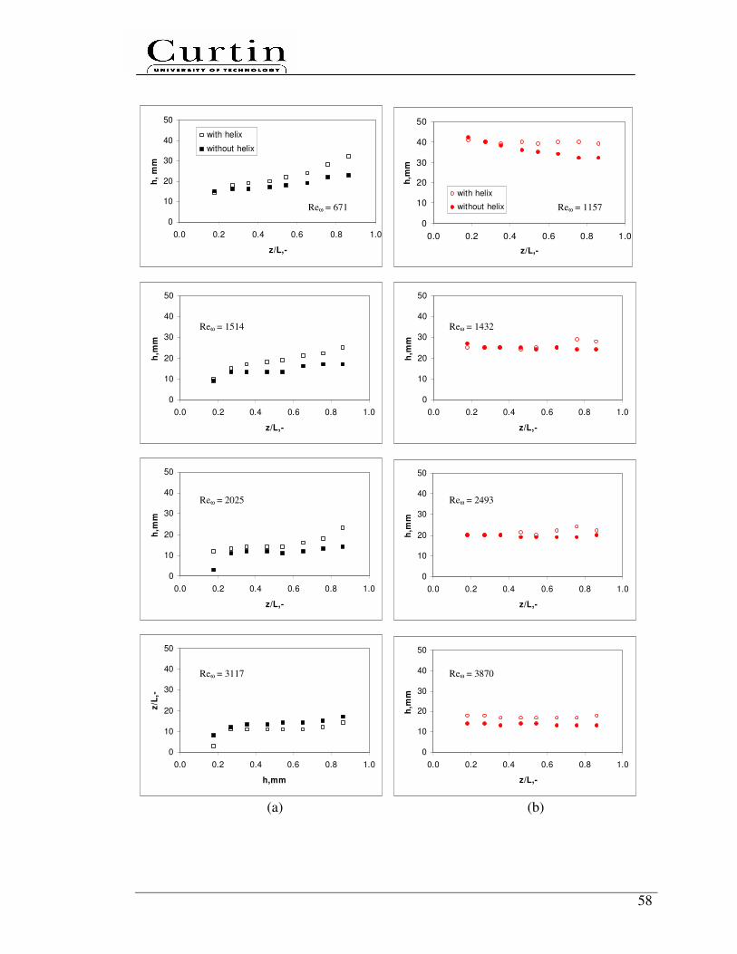
58
0
10
20
30
40
50
0.0 0.2 0.4 0.6 0.8 1.0
z/L,-
h,
mm
with helix
without helix
0
10
20
30
40
50
0.0 0.2 0.4 0.6 0.8 1.0
z/L,-
h,m
m
with helix
without helix
0
10
20
30
40
50
0.0 0.2 0.4 0.6 0.8 1.0
z/L,-
h,m
m
0
10
20
30
40
50
0.0 0.2 0.4 0.6 0.8 1.0
z/L,-
h,m
m
0
10
20
30
40
50
0.0 0.2 0.4 0.6 0.8 1.0
z/L,-
h,m
m
0
10
20
30
40
50
0.0 0.2 0.4 0.6 0.8 1.0
z/L,-
h,m
m
0
10
20
30
40
50
0.0 0.2 0.4 0.6 0.8 1.0
h,mm
z/L
,-
0
10
20
30
40
50
0.0 0.2 0.4 0.6 0.8 1.0
z/L,-
h,m
m
(a) (b)
Reω = 671 Reω = 1157
Reω = 1432 Reω = 1514
Reω = 2493 Reω = 2025
Reω = 3117 Reω = 3870
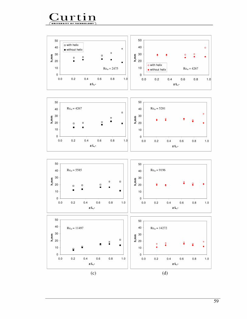
59
0
10
20
30
40
50
0.0 0.2 0.4 0.6 0.8 1.0
z/L,-
h,m
m
with helix
without helix
0
10
20
30
40
50
0.0 0.2 0.4 0.6 0.8 1.0
z/L,-
h,m
m
with helix
without helix
0
10
20
30
40
50
0.0 0.2 0.4 0.6 0.8 1.0
z/L,-
h,m
m
0
10
20
30
40
50
0.0 0.2 0.4 0.6 0.8 1.0
z/L,-
h,m
m
0
10
20
30
40
50
0.0 0.2 0.4 0.6 0.8 1.0
z/L,-
h,m
m
0
10
20
30
40
50
0.0 0.2 0.4 0.6 0.8 1.0
z/L,-
h,m
m
0
10
20
30
40
50
0.0 0.2 0.4 0.6 0.8 1.0
z/L,-
h,m
m
0
10
20
30
40
50
0.0 0.2 0.4 0.6 0.8 1.0
z/L,-
h,m
m
(c) (d)
Reω = 2475 Reω = 4267
Reω = 4267 Reω = 5281
Reω = 9196 Reω = 5585
Reω = 11497 Reω = 14272

60
Figure 4.7. The axial bed depth profiles in horizontal rotating kilns with segmented
lifters and with or without helix at different Reω of (a) glass bead and (b) sand in a kiln
with L/D = 10; (c) glass bead and (d) sand in a kiln with L/D = 5.
4.2 Effect of design equations on prediction equations in horizontal
rotating kilns with segmented lifters
In this section, a systematic experimental program was carried out using the cold kilns to
quantitatively investigate the effect of design equations, i.e. dynamic ratio of the system,
solid characteristics, geometric ratio of the system, on solid transport prediction
equations, i.e. f, Cu.
4.2.1 Dynamic ratios
Figure 4.8 illustrates the dependence of f and Cu in underloading regime (f < 10 %) at
different Reω . Figure 4.8 clearly shows that f decreases with increasing Reω, and there
are rapid increase in f for glass bead and sand at Reω < ~1500 and ~3000. This is
expected because a higher Reω leading to faster solid transport therefore lower solid
inventory. Higher Reω translates into greater inertial forces (mainly due to high kiln
rotational speeds) so that lifters have more energy to scoop and lift solid into the upper
part of the kiln until its angle of repose and spill the solid under the influence of gravity.
As a result of the folded lifter sections, when the solid are scooped, the solid physically
push toward kiln discharge end along the bed arc length, leading to axial solid
displacement. The solid then fall from the lifters at the same time and enters into contact
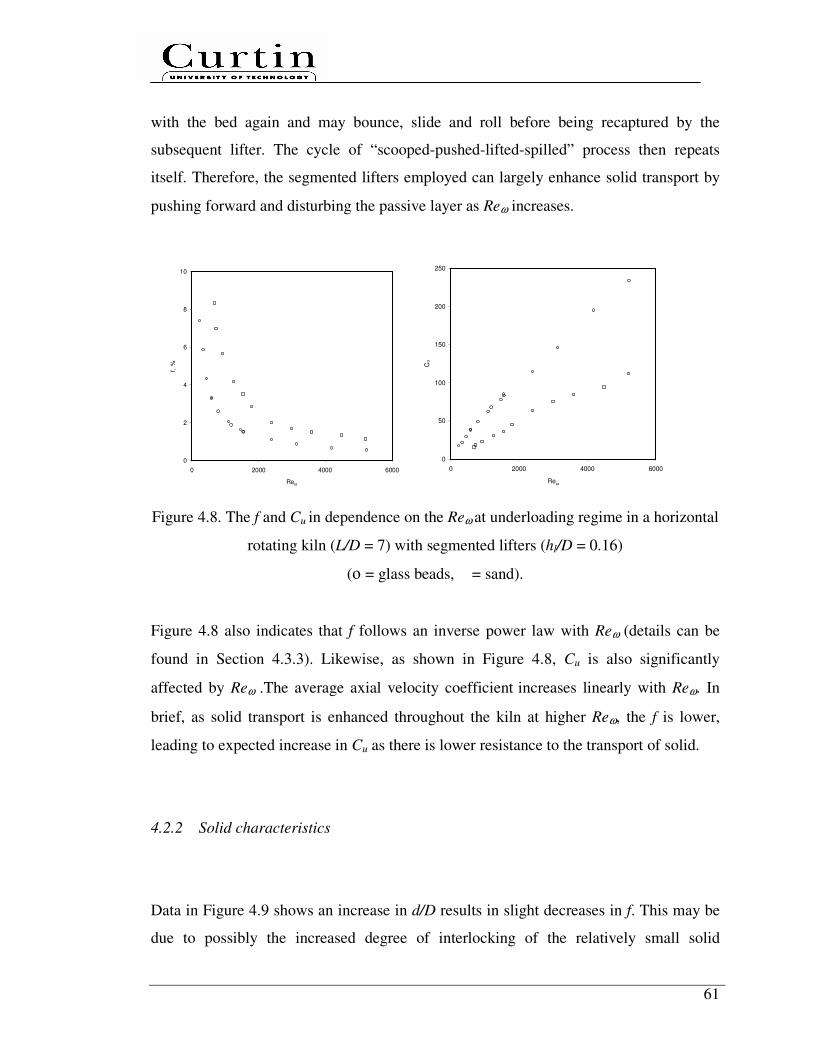
61
with the bed again and may bounce, slide and roll before being recaptured by the
subsequent lifter. The cycle of “scooped-pushed-lifted-spilled” process then repeats
itself. Therefore, the segmented lifters employed can largely enhance solid transport by
pushing forward and disturbing the passive layer as Reω increases.
0
2
4
6
8
10
0 2000 4000 6000
Reω
f, %
0
50
100
150
200
250
0 2000 4000 6000
Reω
Cu
Figure 4.8. The f and Cu in dependence on the Reω at underloading regime in a horizontal
rotating kiln (L/D = 7) with segmented lifters (hl/D = 0.16)
(ο = glass beads, � = sand).
Figure 4.8 also indicates that f follows an inverse power law with Reω (details can be
found in Section 4.3.3). Likewise, as shown in Figure 4.8, Cu is also significantly
affected by Reω .The average axial velocity coefficient increases linearly with Reω. In
brief, as solid transport is enhanced throughout the kiln at higher Reω, the f is lower,
leading to expected increase in Cu as there is lower resistance to the transport of solid.
4.2.2 Solid characteristics
Data in Figure 4.9 shows an increase in d/D results in slight decreases in f. This may be
due to possibly the increased degree of interlocking of the relatively small solid
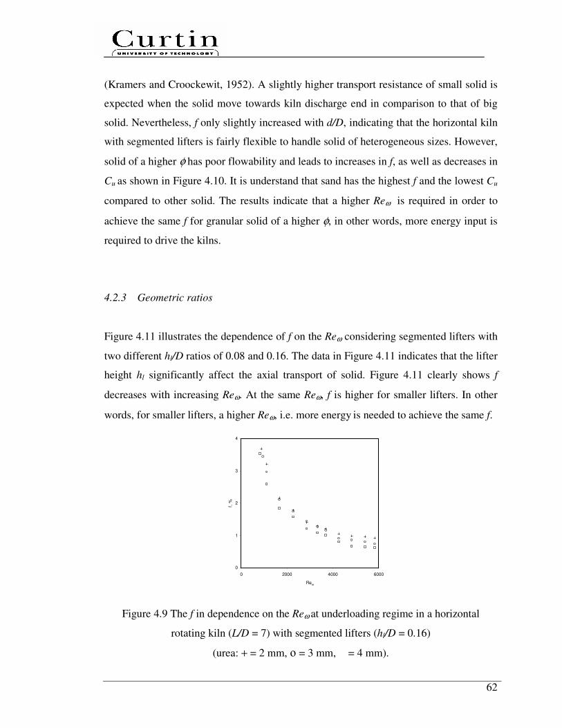
62
(Kramers and Croockewit, 1952). A slightly higher transport resistance of small solid is
expected when the solid move towards kiln discharge end in comparison to that of big
solid. Nevertheless, f only slightly increased with d/D, indicating that the horizontal kiln
with segmented lifters is fairly flexible to handle solid of heterogeneous sizes. However,
solid of a higher φ has poor flowability and leads to increases in f, as well as decreases in
Cu as shown in Figure 4.10. It is understand that sand has the highest f and the lowest Cu
compared to other solid. The results indicate that a higher Reω is required in order to
achieve the same f for granular solid of a higher φ, in other words, more energy input is
required to drive the kilns.
4.2.3 Geometric ratios
Figure 4.11 illustrates the dependence of f on the Reω considering segmented lifters with
two different hl/D ratios of 0.08 and 0.16. The data in Figure 4.11 indicates that the lifter
height hl significantly affect the axial transport of solid. Figure 4.11 clearly shows f
decreases with increasing Reω. At the same Reω, f is higher for smaller lifters. In other
words, for smaller lifters, a higher Reω, i.e. more energy is needed to achieve the same f.
0
1
2
3
4
0 2000 4000 6000
Reω
f, %
Figure 4.9 The f in dependence on the Reω at underloading regime in a horizontal
rotating kiln (L/D = 7) with segmented lifters (hl/D = 0.16)
(urea: + = 2 mm, ο = 3 mm, � = 4 mm).
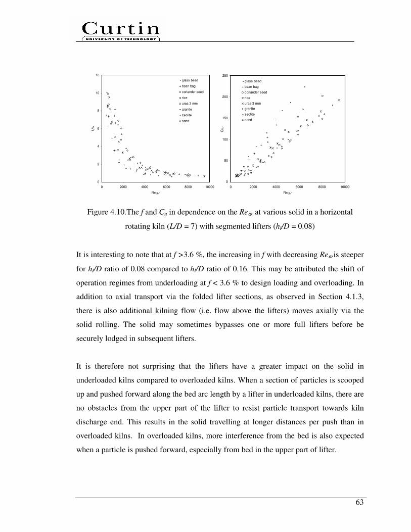
63
0
2
4
6
8
10
12
0 2000 4000 6000 8000 10000
Reω,-
f,%
glass bead
bean bag
coriander seed
rice
urea 3 mm
granite
zeolite
sand
0
50
100
150
200
250
0 2000 4000 6000 8000 10000
Reω,-
Cu,-
glass bead
bean bag
coriander seed
rice
urea 3 mm
granite
zeolite
sand
Figure 4.10.The f and Cu in dependence on the Reω at various solid in a horizontal
rotating kiln (L/D = 7) with segmented lifters (hl/D = 0.08)
It is interesting to note that at f >3.6 %, the increasing in f with decreasing Reω is steeper
for hl/D ratio of 0.08 compared to hl/D ratio of 0.16. This may be attributed the shift of
operation regimes from underloading at f < 3.6 % to design loading and overloading. In
addition to axial transport via the folded lifter sections, as observed in Section 4.1.3,
there is also additional kilning flow (i.e. flow above the lifters) moves axially via the
solid rolling. The solid may sometimes bypasses one or more full lifters before be
securely lodged in subsequent lifters.
It is therefore not surprising that the lifters have a greater impact on the solid in
underloaded kilns compared to overloaded kilns. When a section of particles is scooped
up and pushed forward along the bed arc length by a lifter in underloaded kilns, there are
no obstacles from the upper part of the lifter to resist particle transport towards kiln
discharge end. This results in the solid travelling at longer distances per push than in
overloaded kilns. In overloaded kilns, more interference from the bed is also expected
when a particle is pushed forward, especially from bed in the upper part of lifter.
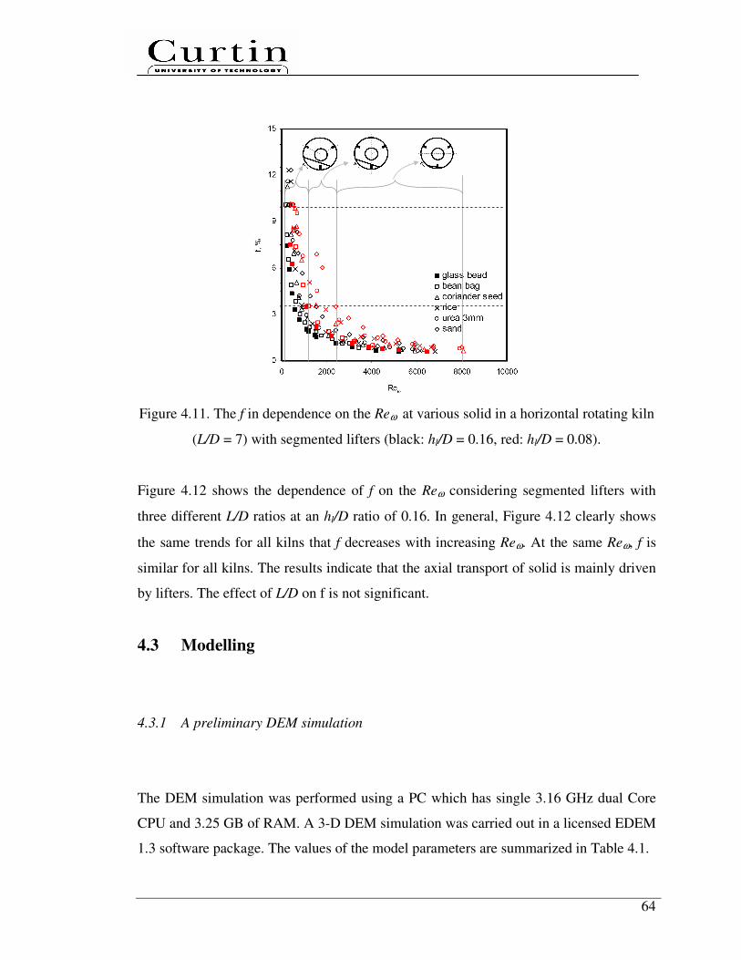
64
Figure 4.11. The f in dependence on the Reω at various solid in a horizontal rotating kiln
(L/D = 7) with segmented lifters (black: hl/D = 0.16, red: hl/D = 0.08).
Figure 4.12 shows the dependence of f on the Reω considering segmented lifters with
three different L/D ratios at an hl/D ratio of 0.16. In general, Figure 4.12 clearly shows
the same trends for all kilns that f decreases with increasing Reω. At the same Reω, f is
similar for all kilns. The results indicate that the axial transport of solid is mainly driven
by lifters. The effect of L/D on f is not significant.
4.3 Modelling
4.3.1 A preliminary DEM simulation
The DEM simulation was performed using a PC which has single 3.16 GHz dual Core
CPU and 3.25 GB of RAM. A 3-D DEM simulation was carried out in a licensed EDEM
1.3 software package. The values of the model parameters are summarized in Table 4.1.
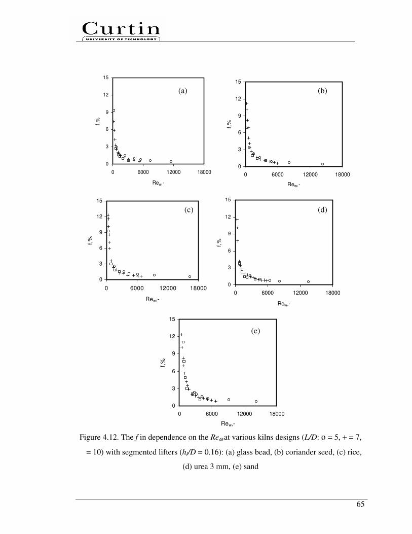
65
0
3
6
9
12
15
0 6000 12000 18000
Rew,-
f,%
0
3
6
9
12
15
0 6000 12000 18000
Rew,-
f,%
0
3
6
9
12
15
0 6000 12000 18000
Rew,-
f,%
0
3
6
9
12
15
0 6000 12000 18000
Rew,-
f,%
0
3
6
9
12
15
0 6000 12000 18000
Rew,-
f,%
Figure 4.12. The f in dependence on the Reω at various kilns designs (L/D: ο = 5, + = 7,
� = 10) with segmented lifters (hl/D = 0.16): (a) glass bead, (b) coriander seed, (c) rice,
(d) urea 3 mm, (e) sand
(a) (b)
(c) (d)
(e)

66
The model solves Newton’s equations of motion, gFdt
udm itotal
ii
rrr
+= , , for each spherical
particle in the system where mi represents the mass of particles i, iur
its velocity, itotalF ,
r
is the total force acting on this particle and gr
is the gravitational acceleration. Vectors
are defined in the traditional Cartesian coordinates with fixed space reference for
position. The Hertz Mindlin contact model (Mindlin, R.D., 1949) is used for calculating
the contact (normal, damping, tangential, tangential damping) forces among particles
due to its accurate and efficient force calculation.
Table 4.1
Input Parameters used for the preliminary DEM simulation
Parameters Values Parameters Values
Poisson’s ratio p,- 0.2 Particle diameter , m 4E-3
Poisson’s ratio w,- 0.29 Particle density, kg/m3
2200
Shear Modulus p, Pa 2.6E+10 Kiln diameter, m 0.51
Shear Modulus w, Pa 8.0E+10 Kiln length, m 3.60
Coefficient of restitution pp, - 0.6 Kiln density, kg/m3
7861
Coefficient of restitution pw, - 0.7 Kiln rotational speed, rpm 3.88
Coefficient of static friction pp, - 0.1 Particle creation rate, particles/s 230
Coefficient of static friction pw, - 0.3 Time step, s 1E-5
Gravitational acceleration, m/s2 (0, -9.8, 0) Initial particle velocity, m/s (0, -0.58, -0.81)
The particle, kiln and lifter properties (density, Poisson’s ratio, shear modulus,
coefficient of restitution and static friction) are based on standard values for glass and
steel, except for particle diameter. The values for kiln rotational speed, particle creation
rate and initial particle velocity were taken from our experiments. Kiln and lifter
geometries with curvature mesh was imported and merged from a Pro/ENGINEER
software package. The model also considers the kiln rotation and lifter geometries,
feeding plate and virtual dynamic surface particle factory. To enable the detection of
contacts in active cells, the domain was divided into grid cells with a size twice as the
particle diameter.

67
Figure 4.13. Orientation snapshot of a horizontal rotating kiln used for the simulation
with particles as vectors, installed segmented lifters (hl/D = 0.16), feeding plate, virtual
dynamic surface particle factory and binning zones
Figure 4.14. Binning zones with 22 zones along the z-direction from 50 to 1100 mm, 1
zone on the y-direction from -225 to 252 mm and 3 zones across the x-direction from -
50 to 80 mm
0 1 2 3 4 5 6 7 8 9 10 11 12 13 14 15 16 17 18 19 20 21
68
To save computation time, the total domain length was shortened and particle diameter
was increased. A domain length was selected that extended 1.2 m down the length of the
kiln from the feed end dam, without having to physically shorten the kiln geometry, as
EDEM permanently removes any particles which pass outside the domain area. This
selected domain length contains an adequate number of lifters to assess their affect on
particle velocity profile. By increasing particle diameter from 2 to 4 mm, the required
particles creation rate per second reduced significantly from 1800 to 230 for a feed rate
of 0.72 kg/min, allowing the simulation to be conducted at a sufficient pass without
being too far from the experimental conditions. Rather than based on a single tracer
particle, results from the simulation were post-processed on multiple-particle velocities
in the z-direction along the kiln within the shortened domain length.
A 3-D internal view of the filled geometries of kiln and segmented lifters is shown in
Figure 4.13. Particles are displayed as vectors. This image shows that the kiln length is
aligned along the z-direction. This mainly has implications for the axial velocity
profiles, as any particles moving toward the kiln discharge end have negative z velocity
values.
Plots were only generated for a specific axial section which not intends to be compared
quantitatively with the results obtained experimentally. The steady-state condition has
not been reached in this study. But the results obtained have already demonstrated the
applicability of DEM simulation for solid flow in a horizontal rotating with segmented
lifters. In Figure 4.14, the binning zones were created to encompass the bed area from
feeding plate to end domain consists of segment–lifter–segment-lifter-segment. The
values across the x-direction were averaged.
Axial velocity profiles were taken at several time increments as the lifters move through
the solid bed. Of key interest is the segment and folded lifter sections areas as this
should be push effect towards to –z-direction. The effect of falling particles into the bed
was eliminated from binning zones. Figure 4.15 shows the axial velocity profiles by
binning zones along the kiln from 75 to 78 seconds, while Figures 4.16a to 4.16d are the
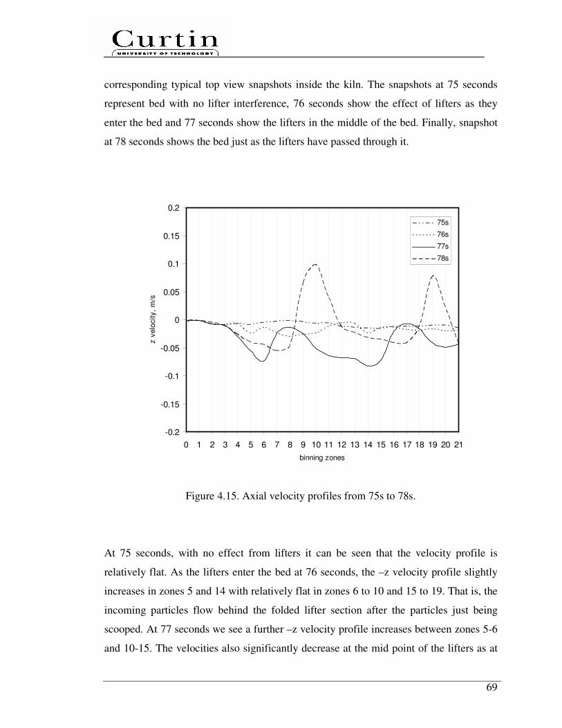
69
corresponding typical top view snapshots inside the kiln. The snapshots at 75 seconds
represent bed with no lifter interference, 76 seconds show the effect of lifters as they
enter the bed and 77 seconds show the lifters in the middle of the bed. Finally, snapshot
at 78 seconds shows the bed just as the lifters have passed through it.
-0.2
-0.15
-0.1
-0.05
0
0.05
0.1
0.15
0.2
0 1 2 3 4 5 6 7 8 9 10 11 12 13 14 15 16 17 18 19 20 21
binning zones
z v
elo
city,
m/s
75s
76s
77s
78s
Figure 4.15. Axial velocity profiles from 75s to 78s.
At 75 seconds, with no effect from lifters it can be seen that the velocity profile is
relatively flat. As the lifters enter the bed at 76 seconds, the –z velocity profile slightly
increases in zones 5 and 14 with relatively flat in zones 6 to 10 and 15 to 19. That is, the
incoming particles flow behind the folded lifter section after the particles just being
scooped. At 77 seconds we see a further –z velocity profile increases between zones 5-6
and 10-15. The velocities also significantly decrease at the mid point of the lifters as at

70
76 seconds. This can be explained by the examination of the bed image at 77 seconds,
which clearly shows a void created as the lifter move along the bed arc length. This
image also demonstrates that a large amount of particles are scooped up by the lifters
and then which fall back to further mix with the incoming bed from both sides (-z and +z
directions). The velocity profile at 78 seconds shows the bed flowing into the voids
which were created at 77 seconds. There are two peaks in +z velocity which are due to
back flow into the voids in zones 10 and 19. Therefore, in addition to enhance axial solid
transport, the installed segmented lifters can be used advantageously to improve axial
solid mixing, which will be further discussed in Chapter 5.
Figure 4.16. Top view snapshots of axial velocity profiles from 75s to 78s
(a) 75s (b) 76s
(c) 77s (d) 78s
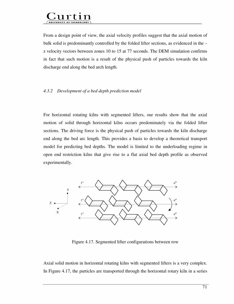
71
From a design point of view, the axial velocity profiles suggest that the axial motion of
bulk solid is predominantly controlled by the folded lifter sections, as evidenced in the –
z velocity vectors between zones 10 to 15 at 77 seconds. The DEM simulation confirms
in fact that such motion is a result of the physical push of particles towards the kiln
discharge end along the bed arch length.
4.3.2 Development of a bed depth prediction model
For horizontal rotating kilns with segmented lifters, our results show that the axial
motion of solid through horizontal kilns occurs predominately via the folded lifter
sections. The driving force is the physical push of particles towards the kiln discharge
end along the bed arc length. This provides a basis to develop a theoretical transport
model for predicting bed depths. The model is limited to the underloading regime in
open end restriction kilns that give rise to a flat axial bed depth profile as observed
experimentally.
Figure 4.17. Segmented lifter configurations between row
Axial solid motion in horizontal rotating kilns with segmented lifters is a very complex.
In Figure 4.17, the particles are transported through the horizontal rotary kiln in a series
Y
X
Z
1st
1st
1st
nth
nth
nth
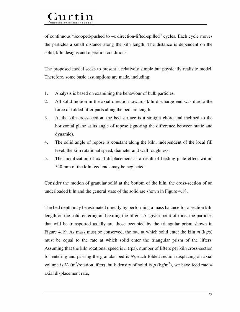
72
of continuous “scooped-pushed to –z direction-lifted-spilled” cycles. Each cycle moves
the particles a small distance along the kiln length. The distance is dependent on the
solid, kiln designs and operation conditions.
The proposed model seeks to present a relatively simple but physically realistic model.
Therefore, some basic assumptions are made, including:
1. Analysis is based on examining the behaviour of bulk particles.
2. All solid motion in the axial direction towards kiln discharge end was due to the
force of folded lifter parts along the bed arc length.
3. At the kiln cross-section, the bed surface is a straight chord and inclined to the
horizontal plane at its angle of repose (ignoring the difference between static and
dynamic).
4. The solid angle of repose is constant along the kiln, independent of the local fill
level, the kiln rotational speed, diameter and wall roughness.
5. The modification of axial displacement as a result of feeding plate effect within
540 mm of the kiln feed ends may be neglected.
Consider the motion of granular solid at the bottom of the kiln, the cross-section of an
underloaded kiln and the general state of the solid are shown in Figure 4.18.
The bed depth may be estimated directly by performing a mass balance for a section kiln
length on the solid entering and exiting the lifters. At given point of time, the particles
that will be transported axially are those occupied by the triangular prism shown in
Figure 4.19. As mass must be conserved, the rate at which solid enter the kiln m (kg/s)
must be equal to the rate at which solid enter the triangular prism of the lifters.
Assuming that the kiln rotational speed is n (rps), number of lifters per kiln cross-section
for entering and passing the granular bed is Nl, each folded section displacing an axial
volume is Vz (m3/rotation.lifter), bulk density of solid is ρ (kg/m
3), we have feed rate =
axial displacement rate,
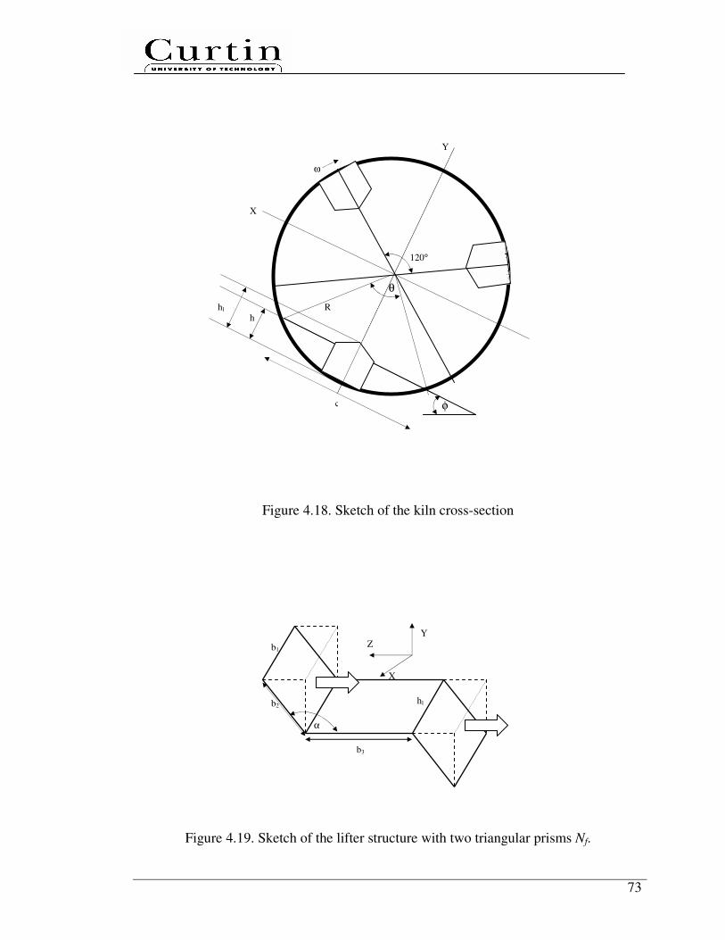
73
Figure 4.18. Sketch of the kiln cross-section
Figure 4.19. Sketch of the lifter structure with two triangular prisms Nf.
X
Y
ω
R
φ
θ
h hl
c
120°
Y
X
Z b1
hl b2
b3
α

74
. . .z l
m V n Nρ= .......................................................................................................... (4.1)
Assuming the bed arc length is La (m), the displaced axial volume per folded lifter
section along the bed arc length can be simplified as a rectangular prism instead of two
triangular prisms (see Figure 4.20). Vz is equal to the product of the number of folded
section per lifter Nf, the length of the rectangular 2
aL (m) and perpendicular cross-
section area Az (m2/folded lifter section):
. .2
az z f
LV A N= ........................................................................................................ (4.2)
Figure 4.20. Displaced axial volume per folded lifter section along the bed arc length
From Figure 4.18, the bed arc length can be determined by
.2. .360
aL R
θπ
°=
°..................................................................................................... (4.3)
La
Az

75
The perpendicular cross-section area Az to the axial displacement can be approximated
as a rectangular geometric shape, which has a height of bed depth h (in case of
underloading regime, h < hl) and a width of b2.sin(180°-α°). We then have
( )2. .sin 180zA h b α= ° − ° ......................................................................................... (4.4)
Considering an arc in a kiln cross-section, the kiln filling angle (subtended by the bed at
the kiln axis θ (°), radius R (m) and chord length c (m) can be related by the following
geometric relationship, as depicted in Figure 4.18:
1sin .
2 2
c
R
θ° =
...................................................................................................... (4.5)
The relation between bed depth h (m) in an inclined bed to the horizontal plane at the
angle of repose of the granular solid φ (°) with chord length c (m) can be determined as
follows:
( )2
tan .hc
φ° = ...................................................................................................... (4.6)
From Eqs. (4.5) and (4.6), eliminating c term and simplifying, gives
( ). tan .sin2
h Rθ
φ°
= °
........................................................................................ (4.7)
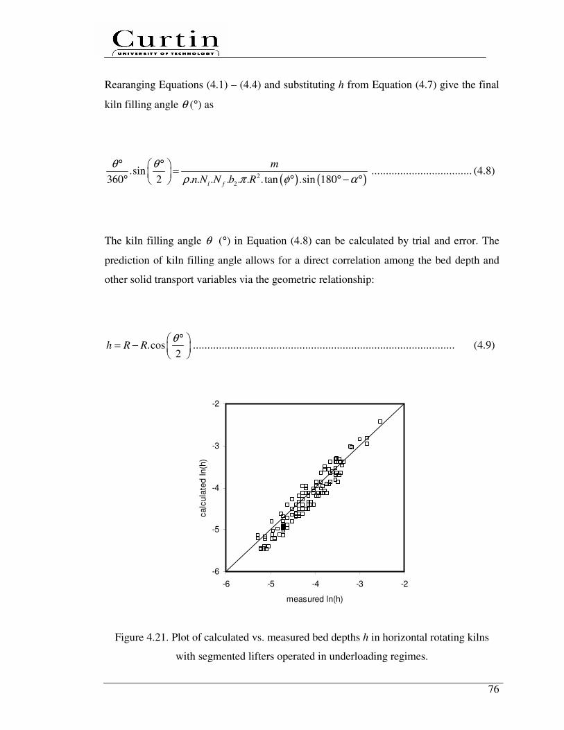
76
Rearanging Equations (4.1) – (4.4) and substituting h from Equation (4.7) give the final
kiln filling angle θ (°) as
( ) ( )2
2
.sin360 2 . . . . . . . tan .sin 180
l f
m
n N N b R
θ θ
ρ π φ α
° ° =
° ° ° − ° ................................... (4.8)
The kiln filling angle θ (°) in Equation (4.8) can be calculated by trial and error. The
prediction of kiln filling angle allows for a direct correlation among the bed depth and
other solid transport variables via the geometric relationship:
.cos2
h R Rθ°
= −
........................................................................................... (4.9)
-6
-5
-4
-3
-2
-6 -5 -4 -3 -2
measured ln(h)
ca
lcu
late
d ln
(h)
Figure 4.21. Plot of calculated vs. measured bed depths h in horizontal rotating kilns
with segmented lifters operated in underloading regimes.
77
The comparisons between the model predicted bed depths and the experimental results
are plotted in Figure 4.21. Figure 4.21 clearly shows that the model predictions are in
good agreement with experimental data in horizontal rotating kilns when various
granular solid under various operating conditions in underloading regimes.
4.3.3 Development of dimensionless empirical correlations
Based on the systematic experiments carried out in this study, a set of dimensionless
correlations has been developed. The three solid transport coefficients can be expressed
by power-law expressions as follows:
( ) ( ) ( ) ( ) ( ) 40.052.003.090.015.014.1 Re91.10−−−−−
= DLDhFrDdf lωφ ............................. (4.10)
( ) ( ) ( ) ( ) ( ) 40.052.003.090.015.014.1 Re57.8−−−−−
= DLDhFrDdC lωτ φ ............................. (4.11)
( ) ( ) ( ) ( ) ( ) 40.052.003.090.015.014.1 Re12.0 DLDhFrDdC lu ωφ −= .................................. (4.12)
Figure 4.22 clearly illustrates that the predictions of the power-law correlations are in
good agreement with the experimental data. The data also shows thatφ, Reω and hl/D
have the most significant impacts on solid transport, as each discussed in Section 4.2.
Beside, the data indicates that the horizontal kiln with segmented lifters has flexibility to
handle solid with a wide range of particle sizes. In presence of lifters, the solid
movement is dominantly driven by the folded lifter sections towards the kiln discharge
end along the bed arc length, in contrast to kilns without lifters, gravitational forces only
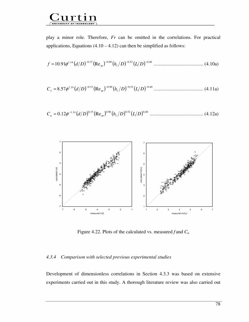
78
play a minor role. Therefore, Fr can be omitted in the correlations. For practical
applications, Equations (4.10 – 4.12) can then be simplified as follows:
( ) ( ) ( ) ( ) 40.052.090.015.014.1 Re91.10−−−−
= DLDhDdf lωφ ....................................... (4.10a)
( ) ( ) ( ) ( ) 40.052.090.015.014.1 Re57.8−−−−
= DLDhDdC lωτ φ ....................................... (4.11a)
( ) ( ) ( ) ( ) 40.052.090.015.014.1 Re12.0 DLDhDdC lu ωφ −= .......................................... (4.12a)
-7
-6
-5
-4
-3
-2
-1
-7 -6 -5 -4 -3 -2 -1
measured ln(f)
ca
lcu
late
d ln
(f)
1
2
3
4
5
6
7
1 2 3 4 5 6 7
measured ln(Cu)
calc
ula
ted l
n(C
u)
Figure 4.22. Plots of the calculated vs. measured f and Cu
4.3.4 Comparison with selected previous experimental studies
Development of dimensionless correlations in Section 4.3.3 was based on extensive
experiments carried out in this study. A thorough literature review was also carried out
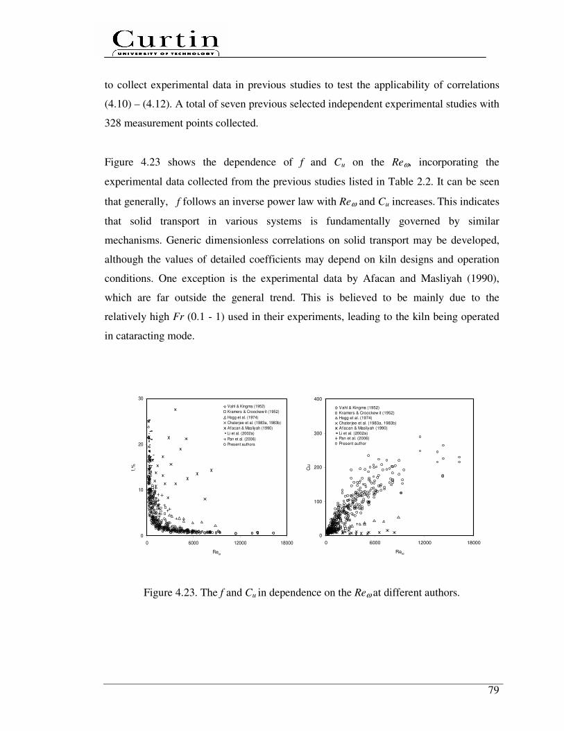
79
to collect experimental data in previous studies to test the applicability of correlations
(4.10) – (4.12). A total of seven previous selected independent experimental studies with
328 measurement points collected.
Figure 4.23 shows the dependence of f and Cu on the Reω, incorporating the
experimental data collected from the previous studies listed in Table 2.2. It can be seen
that generally, f follows an inverse power law with Reω and Cu increases. This indicates
that solid transport in various systems is fundamentally governed by similar
mechanisms. Generic dimensionless correlations on solid transport may be developed,
although the values of detailed coefficients may depend on kiln designs and operation
conditions. One exception is the experimental data by Afacan and Masliyah (1990),
which are far outside the general trend. This is believed to be mainly due to the
relatively high Fr (0.1 - 1) used in their experiments, leading to the kiln being operated
in cataracting mode.
0
10
20
30
0 6000 12000 18000
Reω
f,%
Vahl & Kingma (1952)
Kramers & Croockew it (1952)
Hogg et al. (1974)
Chaterjee et al. (1983a, 1983b)
Afacan & Masliyah (1990)
Li et al. (2002a)
Pan et al. (2006)
Present authors
0
100
200
300
400
0 6000 12000 18000
Reω
Cu
Vahl & Kingma (1952)
Kramers & Croockew it (1952)
Hogg et al. (1974)
Chaterjee et al. (1983a, 1983b)
Afacan & Masliyah (1990)
Li et al. (2002a)
Pan et al. (2006)
Present author
Figure 4.23. The f and Cu in dependence on the Reω at different authors.

80
At a relatively small kiln axis slope without lifters, experiments by Chaterjee et al.
(1983a, 1983b), Kramers and Croockewit (1952) and Vahl and Kingma (1952) showed
relatively higher f values at the same Reω. For rotating kilns without lifters, the axial
transport of granular solid mainly occurs in the thin active layer of bed surface, while
solid in the passive layer under bed surface only turn around the kiln axis with little axial
displacement. This is the phenomena of cascading mode in transversal bed motion
described by Henein et al. (1983).
Part of the experimental data by Hogg et al. (1974), Li et al. (2002a) and Pan et al.
(2006) also showed higher f values than those of the present study at the same Reω. This
is most likely due to the differences in the types of lifters and the end constrictions. As
this study utilises segmented lifters, the segmented lifters are more effective in
enhancing solid transport, leading to a lower f at the same Reω. Practically, a high f is
required for maintaining certain productivity, but f must not be too large (overloading
regime) to affect solid mixing. A lower f also leads to a flat bed depth profile therefore
improving load balance and good heat transfer performances.
It should also be noted that in Figure 4.23 (Cu vs Reω), experimental data by Hogg et al.
(1974), Kramers and Croockewit (1952), Pan et al. (2006) and; Vahl and Kingma (1952)
are mostly well below the experimental data obtained in this study. This is mainly due to
a high Fr used by Hogg et al. (1974), a small kiln axis slope (<1°) without lifters used by
Kramers and Croockewit (1952), types of lifters used by Pan et al. (2006), and a kiln
axis slope of 0° without lifters used by Vahl and Kingma (1952).
Table 4.2 summarizes the range of dimensionless numbers used in experiments for the
development of correlations in each study. Therefore, the comparisons indicate that
extrapolation of the correlations beyond the range could be risky. The developed
dimensionless correlations are largely specific to the current lifters.
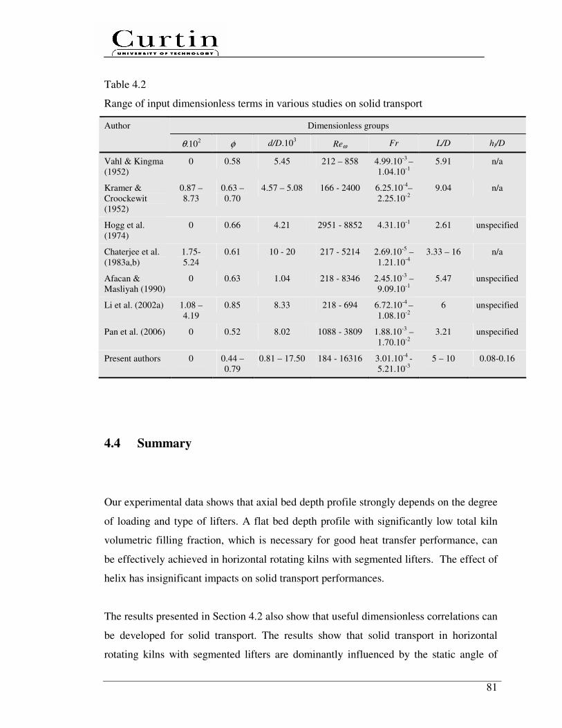
81
Table 4.2
Range of input dimensionless terms in various studies on solid transport
Dimensionless groups Author
θ.102 φ d/D.10
3 Reω Fr
L/D hl/D
Vahl & Kingma
(1952)
0 0.58 5.45 212 – 858 4.99.10-3
–
1.04.10-1
5.91 n/a
Kramer &
Croockewit
(1952)
0.87 –
8.73
0.63 –
0.70
4.57 – 5.08 166 - 2400 6.25.10-4
–
2.25.10-2
9.04 n/a
Hogg et al.
(1974)
0 0.66 4.21 2951 - 8852 4.31.10-1
2.61 unspecified
Chaterjee et al.
(1983a,b)
1.75-
5.24
0.61 10 - 20 217 - 5214 2.69.10-5
–
1.21.10-4
3.33 – 16 n/a
Afacan &
Masliyah (1990)
0 0.63 1.04 218 - 8346 2.45.10-3
–
9.09.10-1
5.47 unspecified
Li et al. (2002a) 1.08 –
4.19
0.85 8.33 218 - 694 6.72.10-4
–
1.08.10-2
6 unspecified
Pan et al. (2006) 0 0.52 8.02 1088 - 3809 1.88.10-3
–
1.70.10-2
3.21 unspecified
Present authors 0 0.44 –
0.79
0.81 – 17.50 184 - 16316 3.01.10-4
-
5.21.10-3
5 – 10 0.08-0.16
4.4 Summary
Our experimental data shows that axial bed depth profile strongly depends on the degree
of loading and type of lifters. A flat bed depth profile with significantly low total kiln
volumetric filling fraction, which is necessary for good heat transfer performance, can
be effectively achieved in horizontal rotating kilns with segmented lifters. The effect of
helix has insignificant impacts on solid transport performances.
The results presented in Section 4.2 also show that useful dimensionless correlations can
be developed for solid transport. The results show that solid transport in horizontal
rotating kilns with segmented lifters are dominantly influenced by the static angle of
82
repose, rotational Reynolds number and lifter height to kiln diameter ratio. Particle size
and Fr have insignificant impact on solid transport, indicating that the horizontal
rotating kilns with segmented lifters are flexible to handle solid with wide size
distribution and forms of transverse motion.
The preliminary DEM simulation confirmed that the axial displacement is mainly due to
folded lifter sections by pushing towards kiln discharge end along the bed arc length. A
simplified theoretical transport model was then developed to predict the average bed
depth in rotating kilns operating in the underloading regimes. A set of dimensionless
empirical correlations has also been derived to predict solid transport. Such global
power-law correlations are universal and physically realistic for practical applications.
The predictions are found to be in good agreement with experimental data.
83
Chapter 5
Solid Mixing
In this chapter, dimensional analysis was performed and a systematic experimental
program was then carried out to quantitatively investigate the effect of segmented lifter
designs, lifter configurations, helix and design equations on solid mixing, considering
various kiln designs, kiln operating conditions and solid physical properties. A
dimensionless empirical correlation has then been developed. The validity was tested
with previous selected mixing experimental studies.
The solid, kiln design and operating condition parameters can affect the bulk solid
mixing variable, namely axial dispersion coefficient Dz in m2/s. This key solid mixing
variable is generally a function of kiln design (kiln length L in m and kiln diameter D in
m), kiln operating conditions (feed rate m in kg/s, kiln rotational speed ω in rad/s), solid
characteristics (mean particle size d in m, particle bulk density ρ in kg/m3, particle static
angle of repose φ in radian), the acceleration of gravity g in m/s2, lifter geometries (lifter
height hl in m)
Based on Buckingham’s Π theorem (Munson et al., 2006), a dimensional analysis has
been carried out. The following applicable correlation is developed among a set of
dimensionless numbers:
Φ==
Dm
D
g
D
D
h
D
L
D
d
D
uLPe l
z
22
3 ,,,,,ρωω
φ

84
The prediction equation is uL/Dz, known as the Peclet number Pe, which is the ratio
between convective and molecular transport. The six design equations are φ, d/D, L/D,
hl/D, ω2D/g and ρωD
2/(m/D). The first and second groups denote the solid
characteristics. The third and fourth groups denote the geometric ratio of the system. The
fifth and sixth groups denote the dynamic ratio of the system. The fifth group is Froude
number Fr, ω2D/g or ω2
R/g, which is the ratio between inertial and gravitational forces.
The sixth group corresponds to the rotational Reynolds number Reω, i.e. the ratio
between inertial forces and the resistant forces which the solid have to overcome.
5.1 Effect of segmented lifter design, lifter configurations and helix
on prediction equation
In this section, a systematic experimental program was carried out using the cold kilns to
quantitatively investigate the presence (inclined kiln without lifters) and effect of
segmented lifter designs (folded lifter section), lifter configurations (single throughout
lifters, number of lifter per row) and helix on solid mixing. All experimental result plots
are limited for urea.
5.1.1 Inclined kiln without lifters
There were several previous experimental studies on solid mixing through horizontal
(Hehl et al., 1978; Mu & Perlmutter, 1980) and inclined (Hatzilyberis et al., 1999a; Sai
et al., 1990; Sudah et al., 2002) rotating kilns without lifters. The details of those studies
are summarised in Table 2.3, which indicates the design variables of rotating kilns and
their value as well as matrix combinations vary greatly among those studies. Therefore,
this study carried out a systematic experimental program to investigate the effect of the
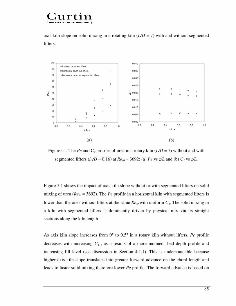
85
axis kiln slope on solid mixing in a rotating kiln (L/D = 7) with and without segmented
lifters.
0
10
20
30
40
50
60
70
80
90
100
0.0 0.2 0.4 0.6 0.8 1.0
z/L, -
Pe
, -
inclined drum w/o lifters
horizontal drum w/o lifters
horizontal drum w/ segmented lifters
0.000
0.005
0.010
0.015
0.020
0.025
0.030
0.035
0.040
0.0 0.2 0.4 0.6 0.8 1.0
z/L, -C
τ,
τ,
τ,
τ,
-
(a) (b)
Figure5.1. The Pe and Cτ profiles of urea in a rotary kiln (L/D = 7) without and with
segmented lifters (hl/D = 0.16) at Reω = 3692: (a) Pe vs z/L and (b) Cτ vs z/L.
Figure 5.1 shows the impact of axis kiln slope without or with segmented lifters on solid
mixing of urea (Reω = 3692). The Pe profile in a horizontal kiln with segmented lifters is
lower than the ones without lifters at the same Reω with uniform Cτ. The solid mixing in
a kiln with segmented lifters is dominantly driven by physical mix via its straight
sections along the kiln length.
As axis kiln slope increases from 0° to 0.5° in a rotary kiln without lifters, Pe profile
decreases with increasing Cτ , as a results of a more inclined bed depth profile and
increasing fill level (see discussion in Section 4.1.1). This is understandable because
higher axis kiln slope translates into greater forward advance on the chord length and
leads to faster solid mixing therefore lower Pe profile. The forward advance is based on

86
the cylinder slope in the axial direction as well as the apparent forward angle of descent
resulting from the transverse flow pattern.
5.1.2 Lifter configurations
Solid mixing in rotary kilns is expected to be influenced by the installed lifters. Key
parameters to be considered include lifter type and configurations. Figure 5.2 shows the
dependence of Pe and Cτ as a function of kiln length of urea at Reω = 3692 in
underloading regimes. The Pe profile of a kiln with single throughout lifters is located
between the inclined kiln without lifters and the horizontal kiln with segmented lifter
while Cτ is the highest and has a non-uniform profile.
As discussed in Section 4.1.2, single throughout lifters have more contact surface area
with solid bed. In the absence of physical push action towards the kiln discharge end as
with segmented lifters, this type of lifters only scoop, lift and spill all solid bed at the
same axial kiln positions considering underloading regimes (f < 10%). Therefore those
actions result in a Pe profile is slightly lower than the inclined kiln without lifters but
higher than the one with segmented lifter. This is due to significantly higher inclined Cτ
profile, corresponding to higher fill level with an inclined bed depth profile. Therefore,
the presence of single throughout lifters only has minor impact on axial solid mixing.
5.1.3 Folded lifter section
The impact of segmented lifters without folded lifter sections, namely segmented
straight lifters, on axial granular solid mixing in horizontal rotating kilns is shown in

87
Figure 5.3. In addition to width b3 of segmented lifter in Figure 3.3, segmented straight
lifters were extended by 0.055 m for each side to compensate the absence of folded lifter
sections. At the same hl/D ratio of 0.16, it is found that the installation of segmented
straight lifters leads to a much lower Pe profile along the kiln, with a non-uniform Cτ
profile.
With the installation of segmented lifters, in addition to scoop and spill solid bed, a
proportion of solid was pushed along the bed arc length and spilled in the negative
(toward to kiln discharge end) and positive (toward to kiln feed end) axial kiln
directions. Additional axial solid mixing occurs. Solid is transferred quicker and mixing
is more intense. However, in absence of the folded section, segmented straight lifters
have reduced contact surface area, resulting in a significantly higher non-uniform Cτ
profile or fill level. It is doubtless that the usage of folded lifter sections is an effective
method to indirectly enhance the axial solid mixing by largely push and spill in the
negative axial kiln directions with a uniform Cτ profile.
0
10
20
30
40
50
60
70
80
90
100
0.0 0.2 0.4 0.6 0.8 1.0
z/L, -
Pe,
-
inclined drum w/o lifters
horizontal drum w/ single-segment lifters
horizontal drum w/ segmented lifters
0.000
0.005
0.010
0.015
0.020
0.025
0.030
0.035
0.040
0.0 0.2 0.4 0.6 0.8 1.0
z/L, -
Cτ
,τ
,τ
,τ
, -
(a) (b)
Figure 5.2. The Pe and Cτ profiles of urea in a rotary kiln (L/D = 7) without lifters and
with single throughout lifters and segmented lifters (hl/D = 0.16) at Reω = 3692: (a) Pe
vs z/L and (b) Cτ vs z/L.
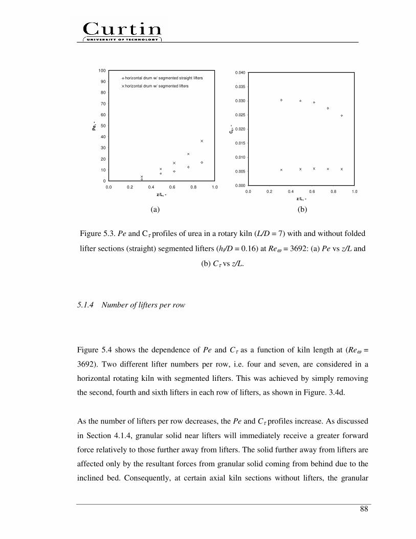
88
0
10
20
30
40
50
60
70
80
90
100
0.0 0.2 0.4 0.6 0.8 1.0
z/L, -
Pe
, -
horizontal drum w/ segmented straight lifters
horizontal drum w/ segmented lifters
0.000
0.005
0.010
0.015
0.020
0.025
0.030
0.035
0.040
0.0 0.2 0.4 0.6 0.8 1.0
z/L, -
Cττ ττ,
-
(a) (b)
Figure 5.3. Pe and Cτ profiles of urea in a rotary kiln (L/D = 7) with and without folded
lifter sections (straight) segmented lifters (hl/D = 0.16) at Reω = 3692: (a) Pe vs z/L and
(b) Cτ vs z/L.
5.1.4 Number of lifters per row
Figure 5.4 shows the dependence of Pe and Cτ as a function of kiln length at (Reω =
3692). Two different lifter numbers per row, i.e. four and seven, are considered in a
horizontal rotating kiln with segmented lifters. This was achieved by simply removing
the second, fourth and sixth lifters in each row of lifters, as shown in Figure. 3.4d.
As the number of lifters per row decreases, the Pe and Cτ profiles increase. As discussed
in Section 4.1.4, granular solid near lifters will immediately receive a greater forward
force relatively to those further away from lifters. The solid further away from lifters are
affected only by the resultant forces from granular solid coming from behind due to the
inclined bed. Consequently, at certain axial kiln sections without lifters, the granular

89
solid start to build-up with less mixing, similar to the case in a horizontal kiln without
lifters. Therefore, the case of seven lifters per row seems to be sufficient in enhancing
both axial solid mixing and transport by consistently push granular solid toward to kiln
discharge end.
0
10
20
30
40
50
60
70
80
90
100
0.0 0.2 0.4 0.6 0.8 1.0
z/L, -
Pe
, -
horizontal drum w/ 12 segmented lifters
horizontal drum w/ segmented lifters
0.000
0.005
0.010
0.015
0.020
0.025
0.030
0.035
0.040
0.0 0.2 0.4 0.6 0.8 1.0
z/L, -
Cττ ττ,
-
(a) (b)
Figure 5.4. The Pe and Cτ profiles of urea in a rotary kiln (L/D = 7) at two different
numbers of lifters per row (hl/D = 0.16) at Reω = 3692: (a) Pe vs z/L and (b) Cτ vs z/L.
5.1.5 Helix
Installation of a helix acts as an additional flow resistance, resulting to a higher f
particularly at near kiln discharge end (see Section 4.1.5). Figure 5.5 and Figure 5.6
shows the profiles of Pe and Cτ of urea in two rotary kilns with and without helix. The
Pe profiles in both kilns with helix are higher than the ones without helix. The data
indicates that the differences increase gradually particularly near drum discharge end
(z/L > 0.8).
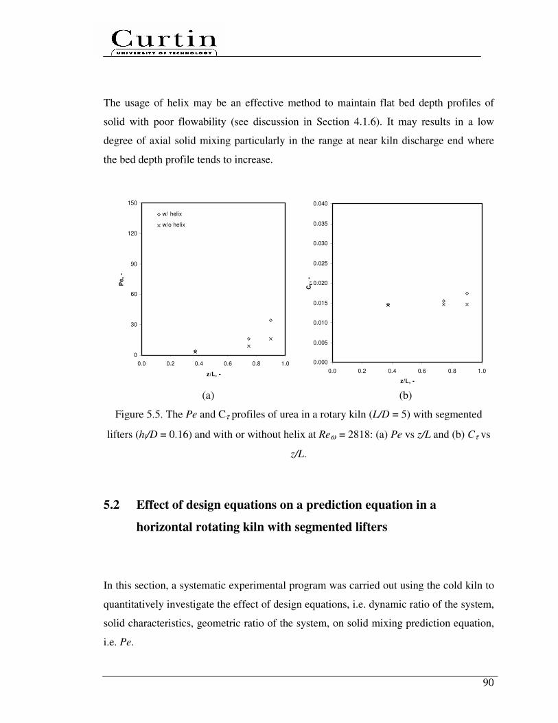
90
The usage of helix may be an effective method to maintain flat bed depth profiles of
solid with poor flowability (see discussion in Section 4.1.6). It may results in a low
degree of axial solid mixing particularly in the range at near kiln discharge end where
the bed depth profile tends to increase.
0
30
60
90
120
150
0.0 0.2 0.4 0.6 0.8 1.0
z/L, -
Pe
, -
w/ helix
w/o helix
0.000
0.005
0.010
0.015
0.020
0.025
0.030
0.035
0.040
0.0 0.2 0.4 0.6 0.8 1.0
z/L, -
Cττ ττ,
-
(a) (b)
Figure 5.5. The Pe and Cτ profiles of urea in a rotary kiln (L/D = 5) with segmented
lifters (hl/D = 0.16) and with or without helix at Reω = 2818: (a) Pe vs z/L and (b) Cτ vs
z/L.
5.2 Effect of design equations on a prediction equation in a
horizontal rotating kiln with segmented lifters
In this section, a systematic experimental program was carried out using the cold kiln to
quantitatively investigate the effect of design equations, i.e. dynamic ratio of the system,
solid characteristics, geometric ratio of the system, on solid mixing prediction equation,
i.e. Pe.

91
0
30
60
90
120
150
0.0 0.2 0.4 0.6 0.8 1.0
z/L, -
Pe
, -
w/ helix
w/o helix
0.000
0.005
0.010
0.015
0.020
0.025
0.030
0.035
0.040
0.0 0.2 0.4 0.6 0.8 1.0
z/L, -
Cττ ττ, -
(a) (b)
Figure 5.6. The Pe and Cτ profiles of urea in a rotary kiln (L/D = 10) with segmented
lifters (hl/D = 0.16) and with or without helix at Reω = 1353: (a) Pe vs z/L and (b) Cτ vs
z/L.
5.2.1 Dynamic ratios
Figure 5.7 illustrates the dependence of Pe in underloading regime (f < 10 %) at
different Reω . Figure 5.7 clearly shows that Pe decreases with increasing Reω, there are
rapid increase in Pe for glass bead and sand at Reω < ~1500 and ~3000. This expected
because a higher Reω leading to faster solid mixing therefore lower Pe. As a result of the
folded and straight lifter section, higher Reω translates into greater inertial force so that
lifters have more energy to scoop, mix, push, mix, lift solid into the upper of the kiln
until its angle of repose, spill the solid under the influence of gravity and mix with solid
bed. The cycle of “scooped-(mixed)-pushed-(mixed)-lifted-spilled-(mixed)” process
then repeats itself. Therefore, the segmented lifters employed can largely enhance solid
mixing by disturbing the passive layer as Reω increases. Figure 5.7 also indicates that Pe
follows an inverse power law with Reω, as discovered in solid transport.

92
0
50
100
150
200
250
0 2000 4000 6000 8000 10000
Re ω,ω,ω,ω, -
Pe,-
sand
glass bead
Figure 5.7. The Pe as a function of Reω at z/L = 0.8 in a rotating kiln (L/D = 7) with
segmented lifters (hl/D = 0.16) using glass bead.
5.2.2 Solid characteristics
Solid mixing in rotary kilns is also expected to be strongly influenced by solid
characteristics. Figure 5.8 presents the data for a range of solids which have different
characteristics, under the same kiln operating conditions. A higher mixing resistance is
expected for granular solid of a smaller d and a higher φ when the solid moves towards
kiln discharge. Solid of smaller size and higher φ have poor flowability and leads to
increases in Pe. In Figure 5.8, sand has the highest Pe compared to other solid.
Therefore, a higher Reω is required in order to achieve the same Pe for granular solid of
a higher φ and a smaller d. In this case, more energy input is required to drive the kilns.
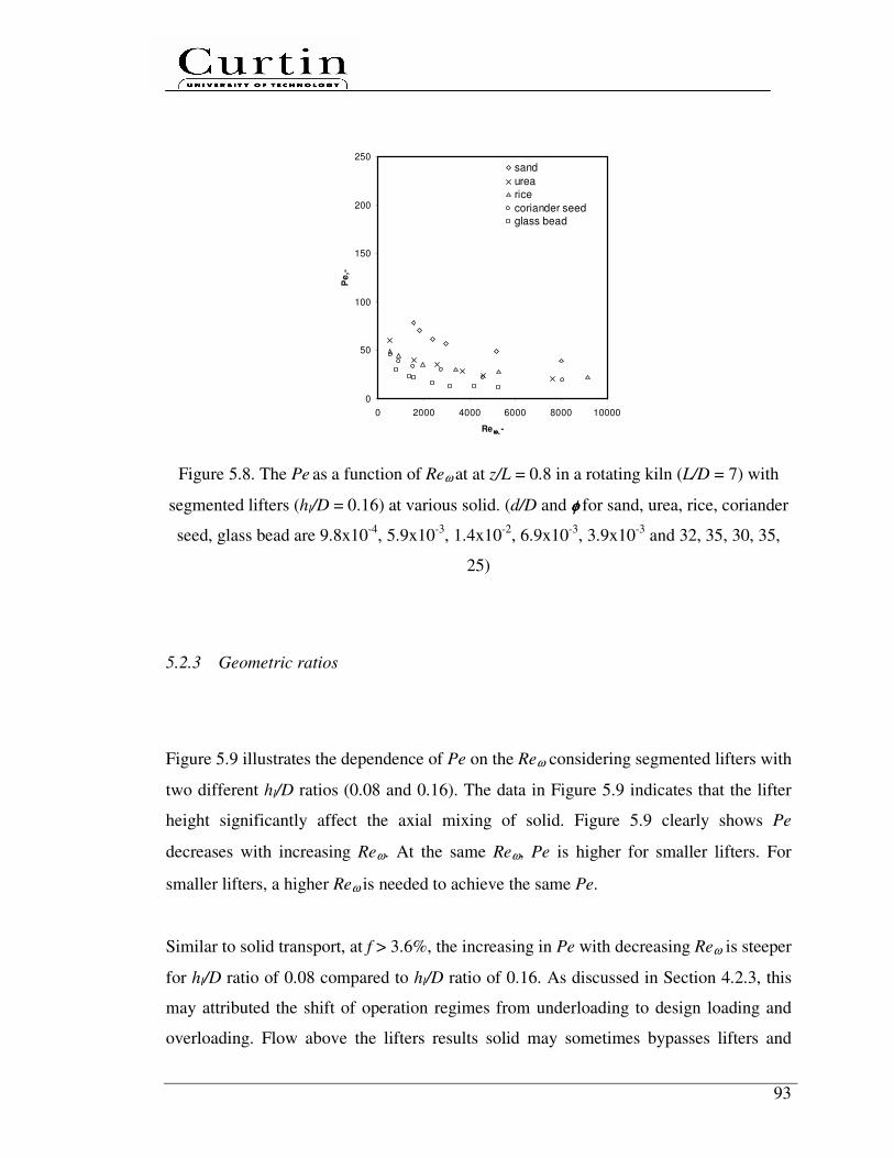
93
0
50
100
150
200
250
0 2000 4000 6000 8000 10000
Re ω,ω,ω,ω, -
Pe
,-
sand
urearice
coriander seedglass bead
Figure 5.8. The Pe as a function of Reω at at z/L = 0.8 in a rotating kiln (L/D = 7) with
segmented lifters (hl/D = 0.16) at various solid. (d/D and φφφφ for sand, urea, rice, coriander
seed, glass bead are 9.8x10⁻⁴
, 5.9x10⁻³
, 1.4x10⁻²
, 6.9x10⁻³
, 3.9x10⁻³
and 32, 35, 30, 35,
25)
5.2.3 Geometric ratios
Figure 5.9 illustrates the dependence of Pe on the Reω considering segmented lifters with
two different hl/D ratios (0.08 and 0.16). The data in Figure 5.9 indicates that the lifter
height significantly affect the axial mixing of solid. Figure 5.9 clearly shows Pe
decreases with increasing Reω. At the same Reω, Pe is higher for smaller lifters. For
smaller lifters, a higher Reω is needed to achieve the same Pe.
Similar to solid transport, at f > 3.6%, the increasing in Pe with decreasing Reω is steeper
for hl/D ratio of 0.08 compared to hl/D ratio of 0.16. As discussed in Section 4.2.3, this
may attributed the shift of operation regimes from underloading to design loading and
overloading. Flow above the lifters results solid may sometimes bypasses lifters and
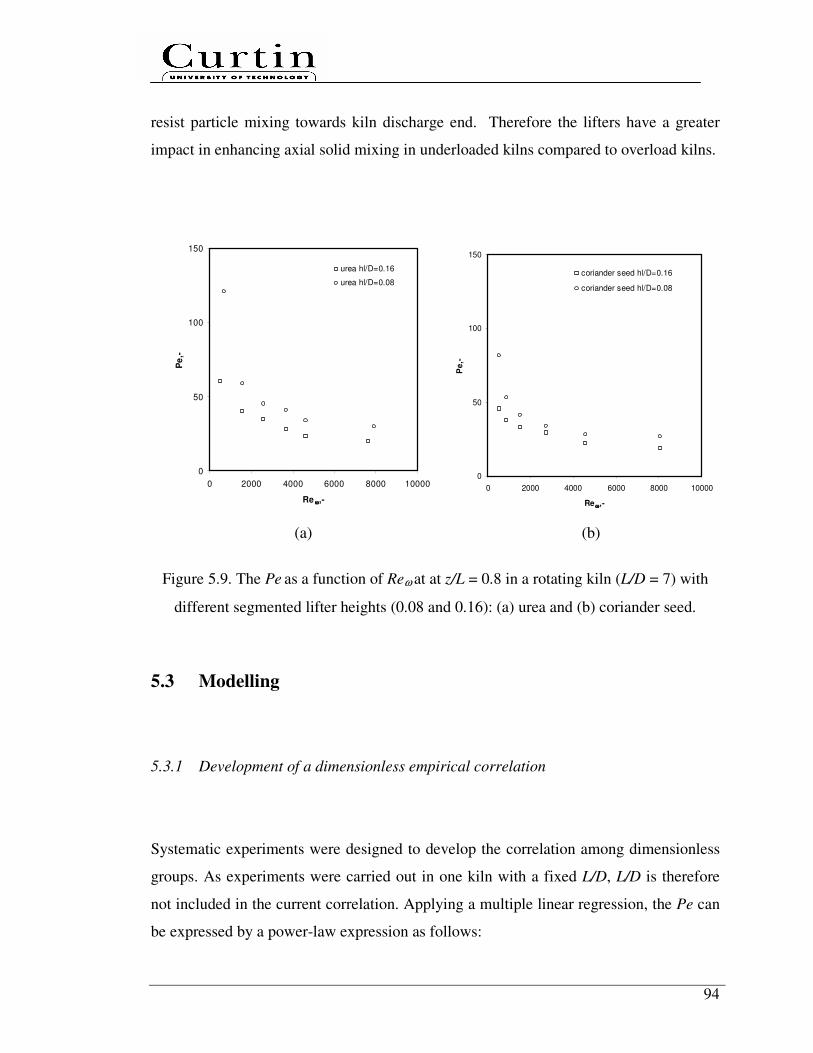
94
resist particle mixing towards kiln discharge end. Therefore the lifters have a greater
impact in enhancing axial solid mixing in underloaded kilns compared to overload kilns.
0
50
100
150
0 2000 4000 6000 8000 10000
Re ωωωω,-
Pe
,-
urea hl/D=0.16
urea hl/D=0.08
0
50
100
150
0 2000 4000 6000 8000 10000
Re ωωωω,-
Pe
,-
coriander seed hl/D=0.16
coriander seed hl/D=0.08
(a) (b)
Figure 5.9. The Pe as a function of Reω at at z/L = 0.8 in a rotating kiln (L/D = 7) with
different segmented lifter heights (0.08 and 0.16): (a) urea and (b) coriander seed.
5.3 Modelling
5.3.1 Development of a dimensionless empirical correlation
Systematic experiments were designed to develop the correlation among dimensionless
groups. As experiments were carried out in one kiln with a fixed L/D, L/D is therefore
not included in the current correlation. Applying a multiple linear regression, the Pe can
be expressed by a power-law expression as follows:
95
( ) ( ) ( ) ( ) 59.001.036.031.005.2 Re.02.108−−−−
= DhFrDdPe lωφ .......................................... (5.1)
Equation (5.1) was developed based on Pe data at a particular kiln axial distance as
shown in Figure 5.10. The dimensionless axial distance of 0.8 was believed to be the
most appropriate to represent the overall degree of axial solid mixing. Axial bed section
at z/L > 0.8 is inappropriate due to the absence of lifters and at z/L < 0.8 is inconsistent
with the final boundary used at z/L = 1 in developing the solid transport correlations (see
in Section 4.3.3). Beside, the difference in coefficients for each dimensionless term at
different z/L is insignificant.
Figure 5.11 clearly illustrates that the predictions of the power-law correlation are in a
good agreement with experimental data, similar to solid transport (see in Section 4.3.3),
the data shows that φ, Reω and hl/D have the most significant impacts on solid mixing,
as each discussed in Section 5.2. Similar to solid transport, the data indicates that the
horizontal kiln with segmented lifters has flexibility to handle solid with a wide range of
particle sizes. Since the solid movement is dominantly driven by folded lifter sections
towards the kiln discharge end along the bed arc length and no longer gravitational
forces dependent, Fr can be omitted in the correlations. For practical applications,
Equation (5.1) can then be simplified as follows:
( ) ( ) ( ) 59.036.031.005.2 Re.02.108−−−
= DhDdPe lωφ .................................................... (5.1a)
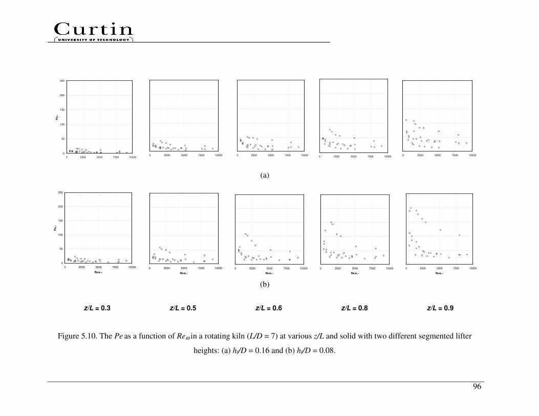
96
0
50
100
150
200
250
0 2500 5000 7500 10000
Pe,-
0 2500 5000 7500 10000
0 2500 5000 7500 10000
0 2500 5000 7500 10000 0 2500 5000 7500 10000
(a)
0
50
100
150
200
250
0 2500 5000 7500 10000
Rew,-
Pe
,-
0 2500 5000 7500 10000
Rew,-
0 2500 5000 7500 10000
Rew,-
0 2500 5000 7500 10000
Rew,-
0 2500 5000 7500 10000
Rew,-
(b)
Figure 5.10. The Pe as a function of Reω in a rotating kiln (L/D = 7) at various z/L and solid with two different segmented lifter
heights: (a) hl/D = 0.16 and (b) hl/D = 0.08.
z/L = 0.3 z/L = 0.6 z/L = 0.8 z/L = 0.9 z/L = 0.5

97
1
2
3
4
5
6
1 2 3 4 5 6
measured ln(Pe)
calc
ula
ted
ln
(Pe
)
Figure 5.11. Comparison between the calculated vs. measured Pe at z/L = 0.8.
5.3.2 Comparison with selected previous experimental studies
A thorough literature review was also carried out to collect experimental data in
previous studies to test the applicability of correlation (5.1). A total of six previous
selected independent experimental studies are selected with 61 measurement points
collected at z/L = 0.8. Figure 5.12 shows the dependence of Pe on the Reω,
incorporating the experimental data collected from the previous studies listed in
Table 2.3. Similar to solid transport, Pe follows an inverse power law with Reω
increases. This indicates that solid mixing in various systems is fundamentally
governed by similar mechanisms. Generic dimensionless correlations on solid
mixing may be developed, although the values of detailed coefficients may depend
on kilns and operation conditions.
There are important findings by directly comparing between Pe in Figure 5.12 and
corresponding f in Figure 5.13, especially the ones reported by Rutgers (1965) and
Venkatarman et al. (1986). Their results show similar Pe compared to the results of
the present study at the same Reω. It is most likely due to significantly higher f (see
discussion in Chapter 4). Rutgers (1965) and Venkatarman et al. (1986) used higher
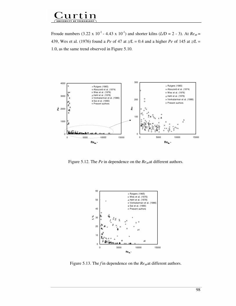
98
Froude numbers (3.22 x 10⁻¹
- 4.43 x 10⁻¹
) and shorter kilns (L/D = 2 - 3). At Reω =
439, Wes et al. (1976) found a Pe of 47 at z/L = 0.4 and a higher Pe of 145 at z/L =
1.0, as the same trend observed in Figure 5.10.
0
1000
2000
3000
4000
0 5000 10000 15000
Reω ,ω ,ω ,ω , -
Pe
-
Rutgers (1965)
Abouzeid et al. (1974)
Wes et al. (1976)
Hehl et al. (1978)
Venkatarman et al. (1986)
Sai et al. (1990)
Present authors
0
100
200
300
0 5000 10000 15000
Reω ,ω ,ω ,ω , -
Pe
-
Rutgers (1965)
Abouzeid et al. (1974)
Wes et al. (1976)
Hehl et al. (1978)
Venkatarman et al. (1986)
Present authors
Figure 5.12. The Pe in dependence on the Reω at different authors.
0
10
20
30
40
50
60
0 5000 10000 15000
Re ω,ω,ω ,ω , -
f, %
Rutgers (1965)
Wes et al. (1976)
Hehl et al. (1978)
Venkatarman et al. (1986)
Sai et al. (1990)
Present authors
Figure 5.13. The f in dependence on the Reω at different authors.
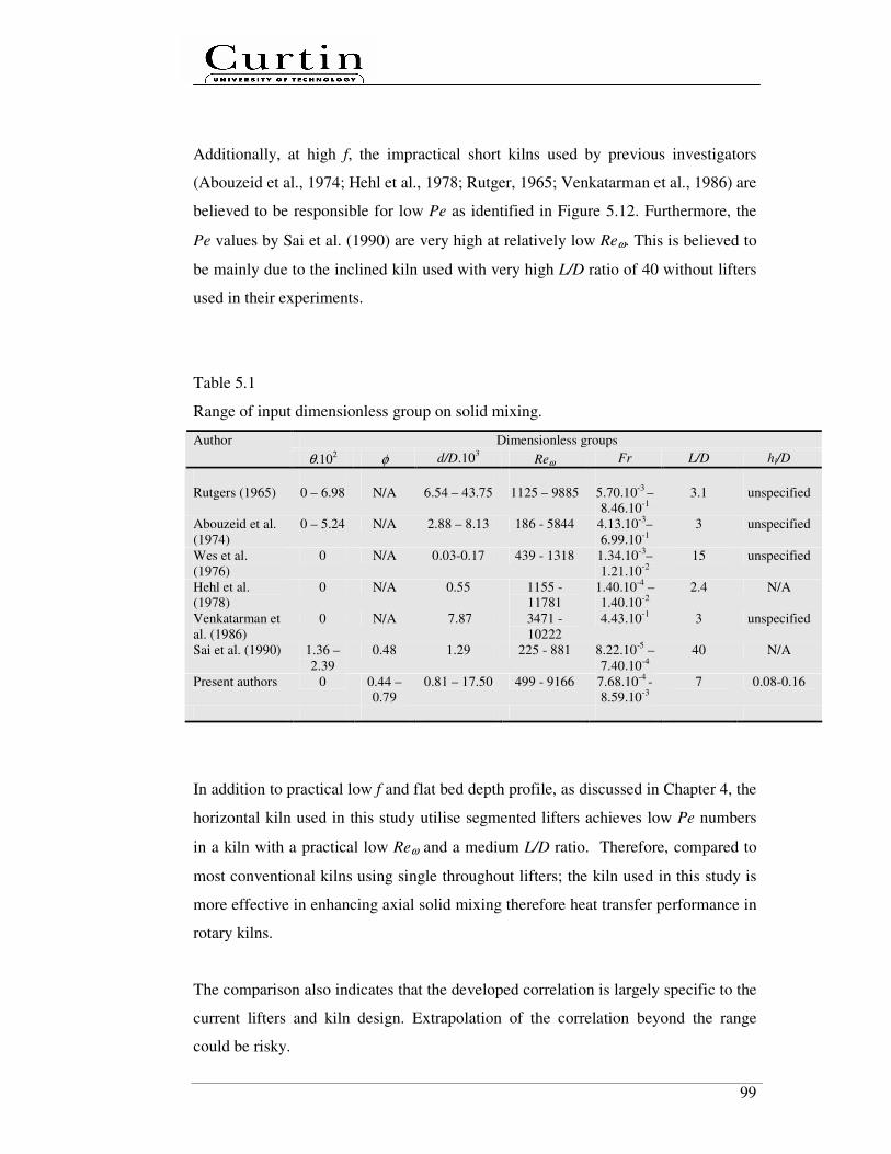
99
Additionally, at high f, the impractical short kilns used by previous investigators
(Abouzeid et al., 1974; Hehl et al., 1978; Rutger, 1965; Venkatarman et al., 1986) are
believed to be responsible for low Pe as identified in Figure 5.12. Furthermore, the
Pe values by Sai et al. (1990) are very high at relatively low Reω. This is believed to
be mainly due to the inclined kiln used with very high L/D ratio of 40 without lifters
used in their experiments.
Table 5.1
Range of input dimensionless group on solid mixing.
Dimensionless groups Author
θ.102 φ d/D.10
3 Reω Fr
L/D hl/D
Rutgers (1965) 0 – 6.98 N/A 6.54 – 43.75 1125 – 9885 5.70.10-3
–
8.46.10-1
3.1 unspecified
Abouzeid et al.
(1974)
0 – 5.24
N/A 2.88 – 8.13 186 - 5844 4.13.10-3
–
6.99.10-1 3 unspecified
Wes et al.
(1976)
0 N/A 0.03-0.17 439 - 1318 1.34.10-3
–
1.21.10-2
15 unspecified
Hehl et al.
(1978)
0
N/A 0.55 1155 -
11781
1.40.10-4
–
1.40.10-2 2.4 N/A
Venkatarman et
al. (1986)
0 N/A 7.87 3471 -
10222
4.43.10-1
3 unspecified
Sai et al. (1990) 1.36 –
2.39
0.48 1.29 225 - 881 8.22.10-5
–
7.40.10-4 40 N/A
Present authors 0 0.44 –
0.79
0.81 – 17.50 499 - 9166 7.68.10-4
-
8.59.10-3
7 0.08-0.16
In addition to practical low f and flat bed depth profile, as discussed in Chapter 4, the
horizontal kiln used in this study utilise segmented lifters achieves low Pe numbers
in a kiln with a practical low Reω and a medium L/D ratio. Therefore, compared to
most conventional kilns using single throughout lifters; the kiln used in this study is
more effective in enhancing axial solid mixing therefore heat transfer performance in
rotary kilns.
The comparison also indicates that the developed correlation is largely specific to the
current lifters and kiln design. Extrapolation of the correlation beyond the range
could be risky.

100
5.4 Summary
The axial solid mixing was studied systematically using continuous rotating kilns
with segmented lifters. Particle mixing dispersion rates were evaluated by Peclet
number. Peclet number is found to be strongly dependent on loading and lifter type.
The experiment results show that in horizontal rotating kilns, a high degree of axial
solid mixing (low Pe) with practical low kiln fill level (<10%), which is necessary
for good heat transfer performances, can be achieved at practical Reω and L/D ratio.
Increasing kiln fill level at a low Reω in overloading regime significantly increased
the Peclet number. Compared to single throughout lifters, segmented lifters has
major impact in enhancing axial solid mixing, via the straight lifter section which
reduces the passive zone in the bed and significantly decreases the bed fill level.
Seven lifters per row were found to be sufficient in enhancing both axial solid
mixing and transport. The installation of helix leads to reduce axial solid mixing,
particularly in the range near kiln discharge end where bed depth tends to increase.
Therefore, in addition to axial solid displacement, the segmented lifters largely
enhance axial solid mixing. The usage of segmented lifters, particularly the
combination of its folded and straight lifter sections is an effective method to
enhance both the axial solid mixing and transport.
Axial solid mixing is also influenced by solid characteristics. A higher Reω is
required in order to achieve the same Pe for granular solid of a higher φ and a
smaller d. The lifter heights hl also significantly affects by axial solid mixing.
The dimensionless empirical correlation on solid mixing has also been derived on the
basis of the experimental results. The angle of repose, rotational Reynolds number
and lifter height to kiln diameter ratio, were found to have most significant impacts
on Peclet number. However, the developed correlations are largely specific to the
current lifters and kiln design.
101
Chapter 6
Heat Transfer
While the previous two chapters focused on investigations to understand the
behaviours of solid transport and mixing, this chapter is devoted to developing a heat
transfer model for a hot kiln with segmented lifters. The model is developed to
predict axial temperature profiles and determine the rate limiting steps among the
heat transfer modes. The present model incorporates the developed axial solid
transport and mixing correlations, and takes into account the suitable heat transfer
modes as well as relevant reaction kinetic parameters of the solid. The input data of
the model was obtained by own experiments or from the literature. The model is
validated by our own experimental data.
6.1 Development of integrated mechanisms
Despite the inclusion of many physical phenomena in the model, certain assumptions
and strategies were made to simplify the task and refine the scope. The assumptions
and strategies are listed below:
1. Discrete solid particles were assumed to be pseudo fluids.
2. The particles were assumed to be spherical and were characterized by the
mean size (diameter).
3. The bed and gas elements were assumed to be distinct, well mixed and
isothermal within a control volume.
4. The temperature of falling is assumed to be same as bed temperature.
5. The gas phase was simply considered as a plug flow model.
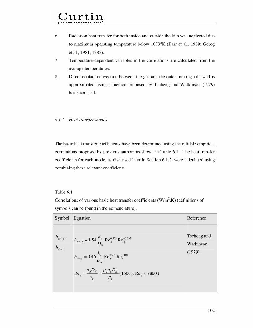
102
6. Radiation heat transfer for both inside and outside the kiln was neglected due
to maximum operating temperature below 1073°K (Barr et al., 1989; Gorog
et al., 1981, 1982).
7. Temperature-dependent variables in the correlations are calculated from the
average temperatures.
8. Direct-contact convection between the gas and the outer rotating kiln wall is
approximated using a method proposed by Tscheng and Watkinson (1979)
has been used.
6.1.1 Heat transfer modes
The basic heat transfer coefficients have been determined using the reliable empirical
correlations proposed by previous authors as shown in Table 6.1. The heat transfer
coefficients for each mode, as discussed later in Section 6.1.2, were calculated using
combining these relevant coefficients.
Table 6.1
Correlations of various basic heat transfer coefficients (W/m2.K) (definitions of
symbols can be found in the nomenclature).
Symbol Equation Reference
gewh − ,
gebh −
292.0575.0ReRe54.1
−− = ωg
H
g
gewD
kh
104.0535.0ReRe46.0 ωg
H
g
gebD
kh =−
g
Hgg
g
Hg
g
Du
v
Du
µ
ρ==Re ( 7800Re1600 << g )
Tscheng and
Watkinson
(1979)

103
g
Hg
g
HD
v
D
µ
ωρωω
22
Re == ( 800Re20 << ω )
( ) ( )2/sin2//sin25.0 θθπθθπ +−+−= iwH DD
owfh −
292.0
,
575.0
,
ReRe54.1−
−−
−
− = owfowf
owfH
f
owfD
kh ω
f
owfHff
f
owfHf
owf
Du
v
Du
µ
ρ −−
− ==,,
Re ( 7800Re1600 << f )
f
owfHf
f
owfH
owf
D
v
D
µ
ωρωω
2
,
2
,
,Re−−
− == ( 800Re20 << ω )
owiiowfH DDD −=−,
Tscheng and
Watkinson
(1979)
iifh −
)PrRe023.0(3/15/4
,
iifiif
iifH
f
iifD
kh −−
−
− =
f
iifHff
f
iifHf
iif
Du
v
Du
µ
ρ −−
− ==,,
Re ( )54 10Re10 << −iif
f
pff
iifk
cµ=−Pr )160Pr5.0( << −iif
owiiiifH DDD −=−,
Incropera
(2007)
cbcwh −
( ) 1
/2/5.0/−
− += φρχ nckkdh pbbbgpcbcw
( )198.0096.0 << χ
Li et al.
(2005)
aoch −
( )( )
2
278169
6/1
Pr/559.01
)Pr(386.06.0
++=
−
−−
aoc
aoc
oc
aaoc
Gr
D
kh
Churchill and
Chu (1975)
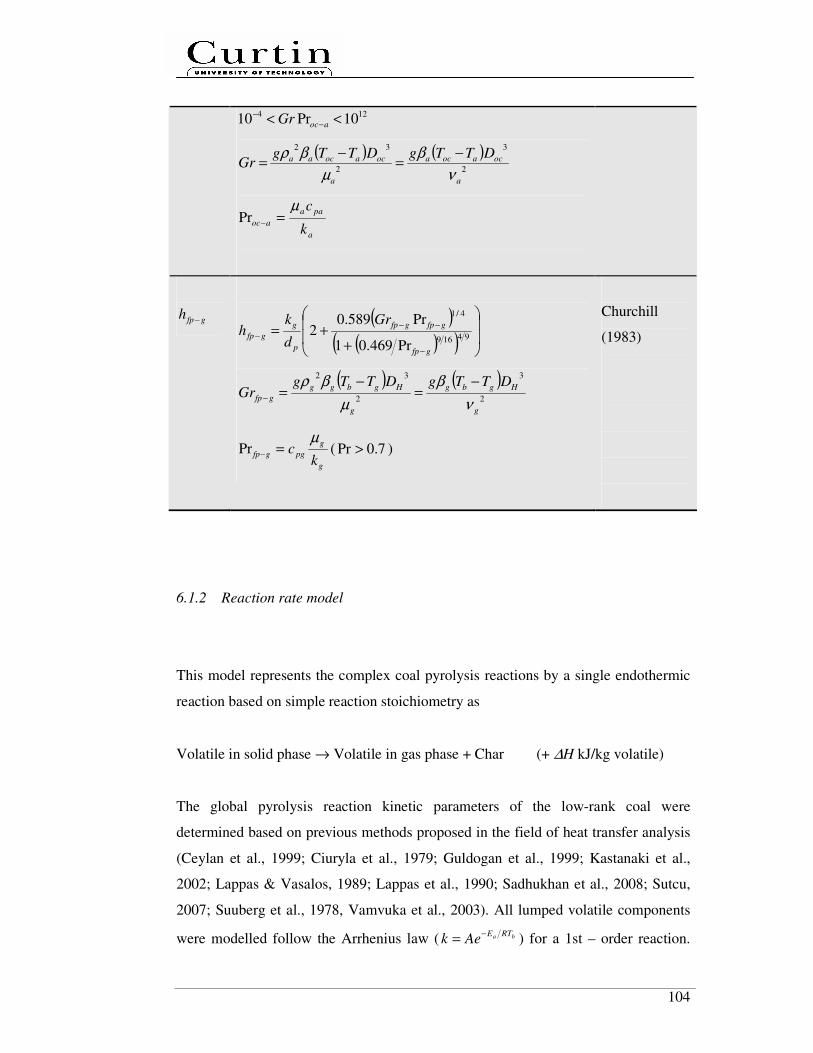
104
124 10Pr10 << −−
aocGr
( ) ( )2
3
2
32
a
ocaoca
a
ocaocaa DTTgDTTgGr
ν
β
µ
βρ −=
−=
a
paa
aock
cµ=−Pr
gfph −
( )( )( )
++=
−
−−
− 94169
4/1
Pr469.01
Pr589.02
gfp
gfpgfp
p
g
gfp
Gr
d
kh
( ) ( )2
3
2
32
g
Hgbg
g
Hgbgg
gfp
DTTgDTTgGr
ν
β
µ
βρ −=
−=−
g
g
pggfpk
cµ
=−Pr ( 7.0Pr > )
Churchill
(1983)
6.1.2 Reaction rate model
This model represents the complex coal pyrolysis reactions by a single endothermic
reaction based on simple reaction stoichiometry as
Volatile in solid phase → Volatile in gas phase + Char (+ ∆H kJ/kg volatile)
The global pyrolysis reaction kinetic parameters of the low-rank coal were
determined based on previous methods proposed in the field of heat transfer analysis
(Ceylan et al., 1999; Ciuryla et al., 1979; Guldogan et al., 1999; Kastanaki et al.,
2002; Lappas & Vasalos, 1989; Lappas et al., 1990; Sadhukhan et al., 2008; Sutcu,
2007; Suuberg et al., 1978, Vamvuka et al., 2003). All lumped volatile components
were modelled follow the Arrhenius law ( ba RTEAek
−= ) for a 1st – order reaction.
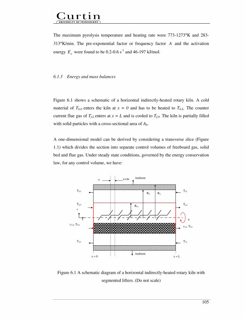
105
The maximum pyrolysis temperature and heating rate were 773-1273°K and 283-
313°K/min. The pre-exponential factor or frequency factor A and the activation
energy aE were found to be 0.2-0.6 s-1
and 46-197 kJ/mol.
6.1.3 Energy and mass balances
Figure 6.1 shows a schematic of a horizontal indirectly-heated rotary kiln. A cold
material of Tb,0 enters the kiln at x = 0 and has to be heated to Tb,L. The counter
current flue gas of Tf,L enters at x = L and is cooled to Tf,0. The kiln is partially filled
with solid particles with a cross-sectional area of Ab.
A one-dimensional model can be derived by considering a transverse slice (Figure
1.1) which divides the section into separate control volumes of freeboard gas, solid
bed and flue gas. Under steady state conditions, governed by the energy conservation
law, for any control volume, we have:
Figure 6.1 A schematic diagram of a horizontal indirectly-heated rotary kiln with
segmented lifters. (Do not scale)
Tg,0
cA,0 ,Tb,0 cA,L Tb,L
Tg,L Riw
r
x
Ambient
n
x = 0 x = L Ambient
Tf,L
Tf,L
Tf,0
Tf,0
Rii Ric
x+∆x x

106
Freeboard gas phase :
gfpgebgew
g
pgg QQQdx
dTcm −−− ++= ........................................................................ (6.1)
Bed phase :
Abbgfpcbcwgebb
pbb rAHQQQdx
dTcm ...ρ∆+++= −−− ................................................... (6.2)
Flue gas phase :
iwfaf
f
pff QQdx
dTcm −− += ................................................................................... (6.3)
As the net energy accumulation within the wall can be neglected, we have,
Wall :
cbcwgewiwf QQQ −−− += .......................................................................................... (6.4)
Considering heat transfer coefficients in Table 6.1, Eqs (6.1-6.4) can be regarded as:
( ) ( ) ( )gbfpgfpgbebgebgwewgew
g
pgg TTAhTTAhTTAhdx
dTcm −+−+−= −−− ...................... (6.5)
( ) ( ) ( )Abbgbfpgfpbwcwcbcwgbebgeb
bpbb rAHTTAhTTAhTTAh
dx
dTcm ...ρ∆+−+−+−= −−−
............................................................................................................................ (6.6)
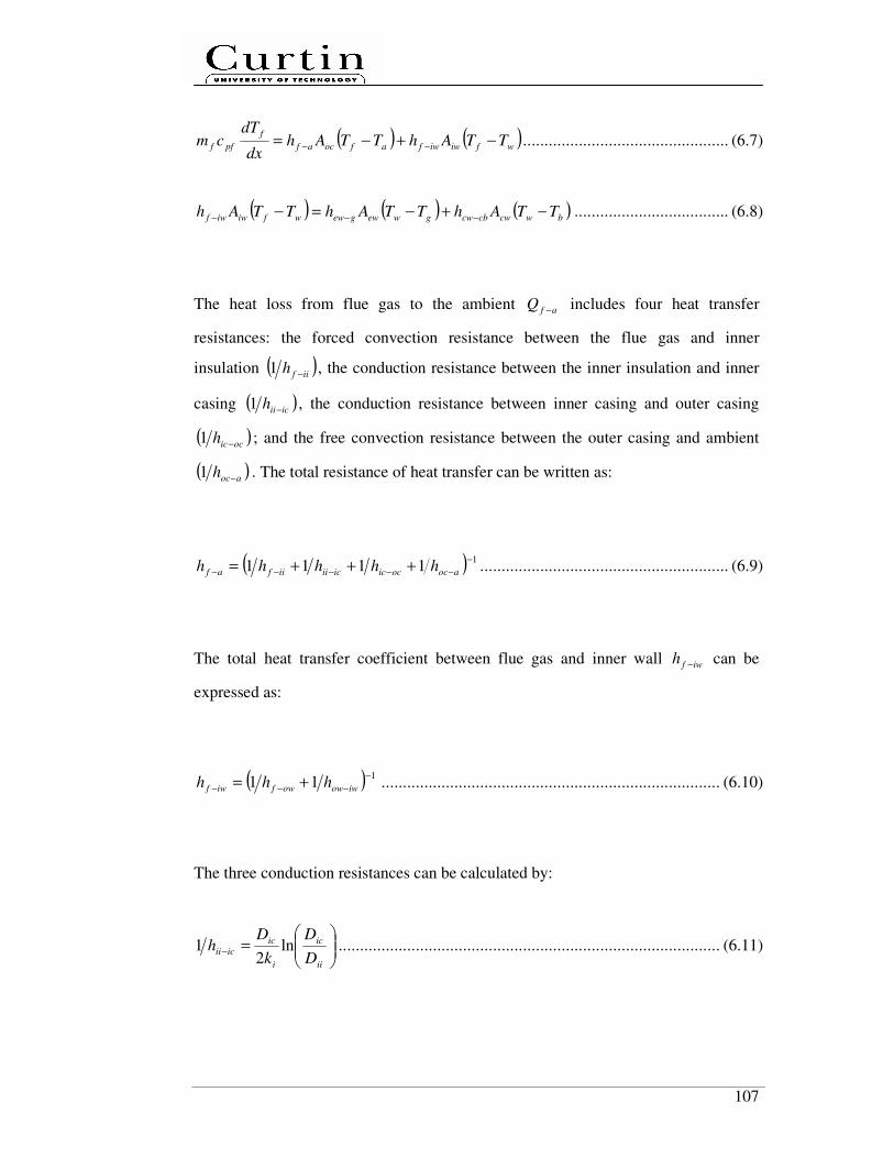
107
( ) ( )wfiwiwfafocaf
f
pff TTAhTTAhdx
dTcm −+−= −− ................................................ (6.7)
( ) ( ) ( )bwcwcbcwgwewgewwfiwiwf TTAhTTAhTTAh −+−=− −−− .................................... (6.8)
The heat loss from flue gas to the ambient afQ − includes four heat transfer
resistances: the forced convection resistance between the flue gas and inner
insulation ( )iifh −1 , the conduction resistance between the inner insulation and inner
casing ( )iciih −1 , the conduction resistance between inner casing and outer casing
( )ocich −1 ; and the free convection resistance between the outer casing and ambient
( )aoch −1 . The total resistance of heat transfer can be written as:
( ) 11111
−
−−−−− +++= aocociciciiiifaf hhhhh .......................................................... (6.9)
The total heat transfer coefficient between flue gas and inner wall iwfh − can be
expressed as:
( ) 111
−
−−− += iwowowfiwf hhh ............................................................................... (6.10)
The three conduction resistances can be calculated by:
=−
ii
ic
i
ic
iciiD
D
k
Dh ln
21 ......................................................................................... (6.11)
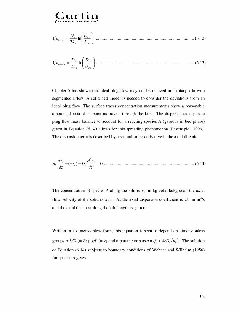
108
=−
ic
oc
w
oc
ocicD
D
k
Dh ln
21 ...................................................................................... (6.12)
=−
ow
iw
w
iw
iwowD
D
k
Dh ln
21 ..................................................................................... (6.13)
Chapter 5 has shown that ideal plug flow may not be realized in a rotary kiln with
segmented lifters. A solid bed model is needed to consider the deviations from an
ideal plug flow. The surface tracer concentration measurements show a reasonable
amount of axial dispersion as travels through the kiln. The dispersed steady state
plug-flow mass balance to account for a reacting species A (gaseous in bed phase)
given in Equation (6.14) allows for this spreading phenomenon (Levenspiel, 1999).
The dispersion term is described by a second-order derivative in the axial direction.
0)(2
2
=−−−dz
cdDr
dz
dcu A
zAA
b .............................................................................. (6.14)
The concentration of species A along the kiln is Ac in kg volatile/kg coal, the axial
flow velocity of the solid is u in m/s, the axial dispersion coefficient is zD in m2/s
and the axial distance along the kiln length is z in m.
Written in a dimensionless form, this equation is seen to depend on dimensionless
groups ubL/D (= Pe), x/L (= z) and a parameter a as2
41 bz ukDa += . The solution
of Equation (6.14) subjects to boundary conditions of Wehner and Wilhelm (1956)
for species A gives
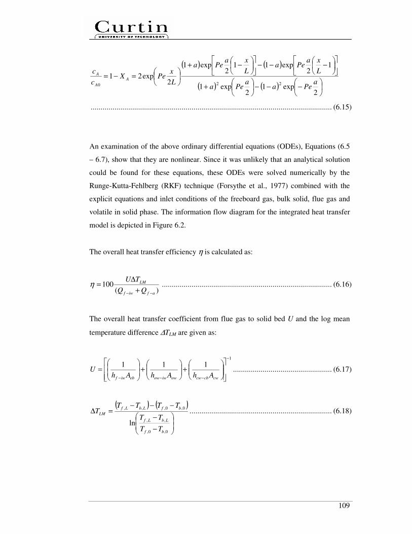
109
( ) ( )
( ) ( )
−−−
+
−−−
−+
=−=
2exp1
2exp1
12
exp112
exp1
2exp21
220a
Peaa
Pea
L
xaPea
L
xaPea
L
xPeX
c
cA
A
A
.......................................................................................................................... (6.15)
An examination of the above ordinary differential equations (ODEs), Equations (6.5
– 6.7), show that they are nonlinear. Since it was unlikely that an analytical solution
could be found for these equations, these ODEs were solved numerically by the
Runge-Kutta-Fehlberg (RKF) technique (Forsythe et al., 1977) combined with the
explicit equations and inlet conditions of the freeboard gas, bulk solid, flue gas and
volatile in solid phase. The information flow diagram for the integrated heat transfer
model is depicted in Figure 6.2.
The overall heat transfer efficiency η is calculated as:
)(100
afiwf
LM
TU
−− +
∆=η ...................................................................................... (6.16)
The overall heat transfer coefficient from flue gas to solid bed U and the log mean
temperature difference ∆TLM are given as:
1
111−
−−−
+
+
=
cwcbcwowiwowebiwf AhAhAhU .................................................. (6.17)
( ) ( )
−
−
−−−=∆
0,0,
,,
0,0,,,
lnbf
LbLf
bfLbLf
LM
TT
TT
TTTTT ........................................................................ (6.18)
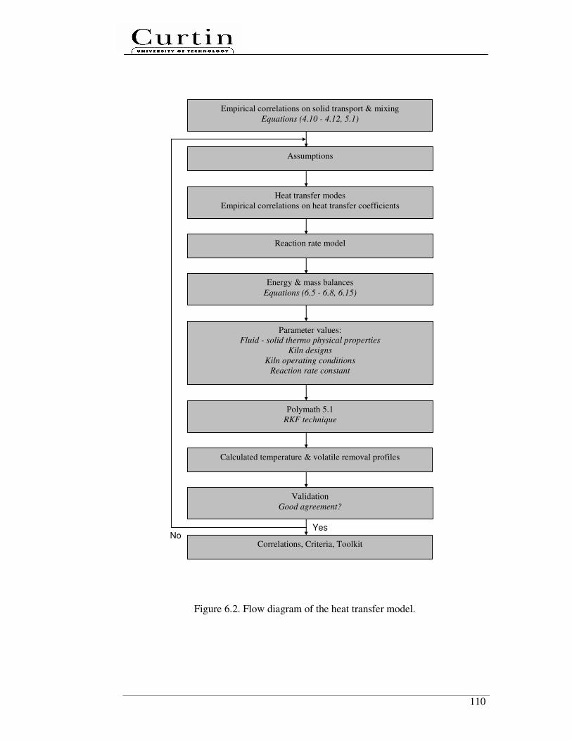
110
Figure 6.2. Flow diagram of the heat transfer model.
Energy & mass balances
Equations (6.5 - 6.8, 6.15)
Assumptions
Parameter values:
Fluid - solid thermo physical properties
Kiln designs
Kiln operating conditions
Reaction rate constant
Heat transfer modes
Empirical correlations on heat transfer coefficients
Empirical correlations on solid transport & mixing
Equations (4.10 - 4.12, 5.1)
Validation
Good agreement?
No Yes
Correlations, Criteria, Toolkit
Polymath 5.1
RKF technique
Calculated temperature & volatile removal profiles
Reaction rate model
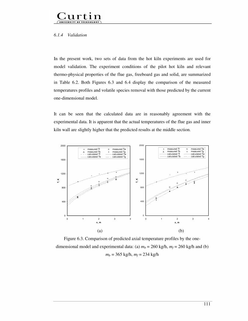
111
6.1.4 Validation
In the present work, two sets of data from the hot kiln experiments are used for
model validation. The experiment conditions of the pilot hot kiln and relevant
thermo-physical properties of the flue gas, freeboard gas and solid, are summarized
in Table 6.2. Both Figures 6.3 and 6.4 display the comparison of the measured
temperatures profiles and volatile species removal with those predicted by the current
one-dimensional model.
It can be seen that the calculated data are in reasonably agreement with the
experimental data. It is apparent that the actual temperatures of the flue gas and inner
kiln wall are slightly higher that the predicted results at the middle section.
0
400
800
1200
1600
2000
0 1 2 3 4
x, m
T,
K
measured Tf measured Twmeasured Tb measured Tgcalculated Tf calculated Twcalculated Tb calculated Tg
0
400
800
1200
1600
2000
0 1 2 3 4
x, m
T,
K
measured Tf measured Twmeasured Tb measured Tgcalculated Tf calculated Twcalculated Tb calculated Tg
(a) (b)
Figure 6.3. Comparison of predicted axial temperature profiles by the one-
dimensional model and experimental data: (a) mb = 260 kg/h, mf = 260 kg/h and (b)
mb = 365 kg/h, mf = 234 kg/h
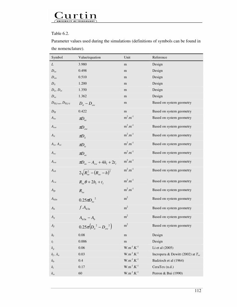
112
Table 6.2.
Parameter values used during the simulations (definitions of symbols can be found in
the nomenclature).
Symbol Value/equation Unit Reference
L 3.980 m Design
Diw 0.498 m Design
Dow 0.510 m Design
Dii 1.200 m Design
Dic, Doi 1.350 m Design
Doc 1.362 m Design
DH,f-ow, DH,f-ii owii DD − m Based on system geometry
DH 0.422 m Based on system geometry
Aiw iwDπ m
2.m
-1 Based on system geometry
Aow owDπ m
2.m
-1 Based on system geometry
Aii iiDπ m
2.m
-1 Based on system geometry
Aic, Aoi icDπ m
2.m
-1 Based on system geometry
Aoc ocDπ m
2.m
-1 Based on system geometry
Aew llcwiw thAD 24 ++−π m
2.m
-1 Based on system geometry
Aeb ( )222 hRR iwiw −− m
2.m
-1 Based on system geometry
Acw lliw thR ++ 2θ m
2.m
-1 Based on system geometry
Afp iwR m
2.m
-1 Based on system geometry
Akiln 2
25.0 iwDπ m
2 Based on system geometry
Ab ln. kiAf m2 Based on system geometry
Ag bki AA −ln m
2 Based on system geometry
Af ( )2225.0 owii DD −π
m2 Based on system geometry
hl 0.08 m Design
tl 0.006 m Design
kg 0.06 W.m-1.K-1 Li et al (2005)
kf , ka 0.03 W.m-1
.K-1
Incropera & Dewitt (2002) at Toc
kb 0.4 W.m-1
.K-1
Badzioch et al (1964)
ki 0.17 W.m-1.K-1 CeraTex (n.d.)
kw 60 W.m-1.K-1 Perron & Bui (1990)

113
ρg 0.857 kg.m-3 Li et al. (2005)
ρf, ρa 1 kg.m-3 Incropera & Dewitt (2002) at Toc
ρb 600 kg.m-3 Measured
µg 8.57 x 10⁻⁷
kg.m-1
.s-1
Calculated (µg =ρg.νg)
µa, µf 2.1 x 10⁻⁵
kg.m-1
.s-1
Incropera & Dewitt (2002) at Toc
νg 1 x 10⁻⁵
m2.s Li et al. (2005)
νa, νf 2.1 x 10⁻⁵
m2.s Incropera & Dewitt (2002) at Toc
cp,g 2920 J.kg-1
.K-1
Design
cp,a 1009 J.kg-1
.K-1
Incropera & Dewitt (2002) at Toc
cp,f 1209 J.kg-1
.K-1
Design
cp,b 1150 J.kg-1.K-1 Agroskin et al. (1970)
ug 0.20 – 0.26 m.s-1
Calculated (mg/ρgAg)
uf 0.07 - 0.08 m.s-1 Calculated (mf/ρfAf)
ub Equation (4.12) m.s-1 Present author
dp 0.03 m Measured
φ 0.79 rad Measured
χ 0.1 - Li et al. (2005)
g 9.80665 m.s-2
-
R 8.314472 J.mol-1
K-1
-
π 3.142857143 - -
Toc 353 K Measured
Ta 293 K Design
n 2 rpm Design
mg 0.4 mb kg.h-1
Design
mb 260 - 325 kg.h-1
Measured
mf (0.2 - 0.5) mg + mair kg.h-1 Design
mair 208 kg.h-1
Design
∆H 3 x 10⁵
J/kg volatile Patisson et al. (2000)
A 0.6 s-1
see in Section 6.1.2
Ea 5.225 x 10⁴
J/mol see in Section 6.1.2
f Equation (4.10) - Present author
θ ( )( ) πθθ 2/sin−=f rad Based on system geometry
h ( )2cos θiwiw RR − m Based on system geometry
H fLD biw ρπ2
25.0 kg Based on system geometry
τ Equation (4.11) s Present author
Pe Equation (5.3-1) - Present author
ew-g 34.1- 40.5 W.m2.K
-1 calculated (see in Table 6.1)

114
g-eb 191.8 – 221.7 W.m2.K-1 calculated (see in Table 6.1)
f-ow 19.4 - 24.0 W.m2.K
-1 calculated (see in Table 6.1)
f-ii 0.7 - 0.9 W.m2.K
-1 calculated (see in Table 6.1)
oc-a 4.6 W.m2.K-1 calculated (see in Table 6.1)
cw-cb 176.4 – 177.1 W.m2.K
-1 calculated (see in Table 6.1)
g-fp 367.3 – 480.6 W.m2.K
-1 calculated (see in Table 6.1)
ii-ic 2.1 W.m2.K
-1 calculated (see in Table 6.1)
ic-oc 9955.9 W.m2.K-1 calculated (see in Table 6.1)
ow-iw 9881.9 W.m2.K
-1 calculated (see in Table 6.1)
f-iw 19.4 - 24.0 W.m2.K
-1 calculated (see in Table 6.1)
f-a 0.5 - 0.6 W.m2.K
-1 calculated (see in Table 6.1)
As shown in Figures 6.3a and 6.3b, the bed temperature at a lower coal feed rate
increased more rapidly along the kiln. The temperature difference between solid bed
and flue gas is also smaller. It can be explained in terms of the role of solid transport
and mixing played in the heat transfer process.
0
0.1
0.2
0.3
0.4
0.5
0 1 2 3 4
x, m
cA
, kg
vo
lati
le/k
g c
oal
predicted at mb = 260 kg/h
predicted at mb = 325 kg/h
Figure 6.4. Predicted volatile species concentration profiles and its comparison with
experimental data (∆ = measured at mb = 260 kg/h, � = measured at mb = 325 kg/h)
Based on Equations (4.10) and (5.1), it should be noted that the kiln fill levels and
Peclet numbers Pe increased from 14 % to 17 % and from 71 to 77, corresponding to
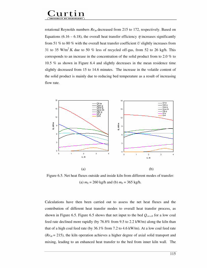
115
rotational Reynolds numbers Reω decreased from 215 to 172, respectively. Based on
Equations (6.16 – 6.18), the overall heat transfer efficiency η increases significantly
from 51 % to 80 % with the overall heat transfer coefficient U slightly increases from
31 to 35 W/m2.K due to 50 % less of recycled off-gas, from 52 to 26 kg/h. This
corresponds to an increase in the concentration of the solid product from to 2.0 % to
10.5 % as shown in Figure 6.4 and slightly decreases in the mean residence time
slightly decreased from 15 to 14.6 minutes. The increase in the volatile content of
the solid product is mainly due to reducing bed temperature as a result of increasing
flow rate.
0
3
6
9
12
15
18
0 1 2 3 4
x, m
Q,
kW
/m
Qf-iwQeb-gQew-gQcw-cbQfp-gQf-aQrA
0
3
6
9
12
15
18
0 1 2 3 4
x, m
Q,
kW
/m
Qf-iwQeb-gQew-gQcw-cbQfp-gQf-aQrA
(a) (b)
Figure 6.5. Net heat fluxes outside and inside kiln from different modes of transfer:
(a) mb = 260 kg/h and (b) mb = 365 kg/h.
Calculations have then been carried out to assess the net heat fluxes and the
contribution of different heat transfer modes to overall heat transfer process, as
shown in Figure 6.5. Figure 6.5 shows that net input to the bed Qcw-cb for a low coal
feed rate declined more rapidly (by 76.8% from 9.5 to 2.2 kW/m) along the kiln than
that of a high coal feed rate (by 36.1% from 7.2 to 4.6 kW/m). At a low coal feed rate
(Reω = 215), the kiln operation achieves a higher degree of axial solid transport and
mixing, leading to an enhanced heat transfer to the bed from inner kiln wall. The

116
wall, bed and freeboard gas temperatures increased along the kiln length rapidly as
shown in Figure 6.3a. The profile of Qf-iw is similar to that of Qcw-cb. While heat loss
from the flue gas to the ambient Qf-a gradually increased along the axial location. Qf-a
at both feed rates has reached 2.7 kW/m at the kiln outlet.
Figure 6.6 shows the contribution of different heat transfer modes (QrA, Qew-g, Qcw-cb,
Qeb-g, and Qfp-g), as a fraction to the total heat flux inside the kiln. Heat transfer from
the covered wall to covered bed (Qcw-cb) plays a key role in overall heat transfer into
the bed. The proportions of Qcw-cb reduce gradually because the difference between
the temperatures of the solid bed and inner kiln wall decreases along the kiln length.
In the initial zone (kiln feed end), the net input to the bed Qcw-cb is lower than the
lower at a higher coal feed rate. This is likely due to the non-uniformity solid load
along the kiln, especially in the initial zone as discussed in Chapter 4. This leads to a
decreased bed depth, therefore heat transfer rate along the kiln length.
0.0
0.1
0.2
0.3
0.4
0 1 2 3 4
x, m
Rela
tive
co
ntr
ibu
tio
n,
as a
fra
cti
on
of
tota
l h
ea
t fl
ux i
ns
ide t
he k
iln
Qeb-g
Qew-g
Qcw-cb
Qfp-g
QrA
0.0
0.1
0.2
0.3
0.4
0 1 2 3 4
x, m
Re
lati
ve
co
ntr
ibu
tio
n,
as
a f
racti
on
of
tota
l h
ea
t fl
ux
in
sid
e t
he
kil
n
Qeb-g
Qew-g
Qcw-cb
Qfp-g
QrA
(a) (b)
Figure 6.6. Contribution of various heat transfer modes inside the kiln:
(a) mb = 260 kg/h and (b) mb = 365 kg/h.

117
The heat required for a chemical reaction was found to make the smallest
contribution (< 5 %) to the overall heat transfer inside the kiln. For heat transfer to
freeboard gas, in comparison to the heat transfer from exposed inner wall (Qew-g) and
exposed bed (Qeb-g), the heat transfer from falling particles (Qfp-g) makes the biggest
contribution to the net heat input to the freeboard gas. Along the kiln length, Qfp-g
retains at steady value of 8 kW/m at a high coal feed rate (see Figure 6.6b),
corresponding to a gradual increase in the bed and freeboard gas temperatures as
shown in Figure 6.3b. As discussed in Chapters 4 and 5, at a higher Reω, lifters have
more energy in enhancing both axial solid transport and mixing by scooping,
pushing, lifting and spilling solid. This leads to an increase in Qfp-g along the kiln.
The predicted Qew-g profiles at the low and high coal feed rates are at steady values of
5.5 and 6.4 kW/m along the kiln, respectively. This is mainly due to a 25% increase
in the freeboard gas produced at a higher coal feed rate.
Heat transfer from exposed bed (Qeb-g) increases coal feed rate, particularly in the
initial zone. This is mainly the 5% increase in the average heat transfer area Aeb, from
0.397 to 0.417 m2/m kiln length. In fact, heat transfer area proportion in the initial
zone was believed to be the highest due to an inclined bed depth profile.
As discussed in Chapters 4 and 5, overloading kilns have an inclined bed depth
profile, corresponding to an increasing axial solid velocity and a decreasing
residence time along the kiln and poor axial solid mixing. The heat transfer non-
uniformity along the kiln length is fundamentally related to solid transport and
mixing therefore must be considered in the design stage. This indicates that heat
transfer from the covered wall to the covered bed is the limiting heat transfer step.
6.2 Summary
An integrated axial heat transfer model has been developed and applied to the
process of low-rank coal pyrolysis in a pilot-scale indirectly heated rotary kiln at two
different coal feed rates, with consideration for the effect of segmented lifters which
118
has not been considered by any axial heat transfer model to date. The reasonable
agreement between the present model predictions and experimental data was
achieved on the effect of feed rates.
The model has provided further insights into the solid transport and mixing processes
occurring within the bed affecting the heat transfer behaviours. The overall heat
transfer efficiency can be significantly increased by 57 % by lowering Reω from 215
to 172 and using 50 % less amount of recycled off gas. However, the volatile species
in coal at the kiln end significantly increased from 2.0 % to 10.5 % as coal feed rate
increased, corresponding to lower Reω. This is due to the kiln was operated in
overloading regime leading to an inclined bed depth profile and poor axial mixing
performances. Among the heat transfer modes, it is clear that heat transfer from the
covered inner kiln wall to the covered bed, which is fundamentally dependent on
solid transport and mixing in the kiln bed, is the limiting step of the overall heat
transfer inside the kiln. Typical values of overall heat transfer coefficient are also
estimated to be 31 - 35 W/m2.K.
119
Chapter 7
Conclusions and Recommendations
This chapter concludes the present study by highlighting the main research findings.
The present research has led to the discovery of new knowledge on solid transport,
solid mixing and heat transfer mechanisms in an indirectly rotary kiln with lifters of
various designs and configurations. The research has developed new dimensionless
correlations on solid transport, solid mixing as well as a steady-state axial heat
transfer model for the kiln with segmented lifters.
7.1 Conclusions
The key findings from the present study are as follows:
1. This study has investigated the effect of segmented lifters on axial solid
transport and solid mixing in horizontal rotary kilns and revealed the
fundamental mechanisms leading to such effect. It is found that the axial bed
depth profile, total kiln volumetric filling fraction and Peclet numbers are
strongly dependent on solid loading, lifter design and lifter configurations.
2. A flat bed depth profile and enhanced axial solid mixing can be effectively
achieved in horizontal rotating kilns with segmented lifters, particularly those
with a design combining both folded and straight sections. The effect of helix
has insignificant impacts on solid transport and mixing performances.
120
3. The preliminary Discrete Element Method (DEM) confirmed that the axial
displacement is mainly due to folded lifter sections, which push the solids
towards kiln discharge end along the bed arc length.
4. A simplified theoretical model has been developed to predict the average
depth in horizontal rotating kilns with segmented lifter, operating in the
underloading regimes. The predictions are in good agreement with
experimental data.
5. A set of useful dimensionless empirical correlations on solid transport and
solid mixing have been developed. Such global power-law correlations are
validated by our experimental data. The results indicate that
• solid transport and mixing in horizontal rotating kilns with segmented
lifters are dominantly influenced by the static angle of repose, rotational
Reynolds number and lifter height to kiln diameter ratio.
• Fr has an insignificant impact on solid transport and mixing, indicating
that in horizontal rotating kilns with segmented lifters, solid transport and
mixing is dominantly driven by lifters, rather than gravity force in kilns
without lifters.
• horizontal rotating kilns with segmented lifters are flexible to handle
solid with wide size distribution.
6. A steady-state axial heat transfer model, validated by experimental data, has
been developed for an indirectly heated horizontal rotary kiln with segmented
lifters. The model incorporates the solid transport and solid mixing
correlations developed in this study. The model predicts the temperature
profiles of the freeboard gas, solid bed, inner kiln wall and flue gas. It is
found that the limiting step is the heat transfer from covered inner kiln wall to
covered bed, which is strongly influenced by solid transport and solid mixing.
121
7.2 Recommendations
Although the overall objectives of the present study have been achieved, there are
still considerable scopes for future research. The recommendations for future study
are listed as follows:
1. In the present study, a wide variety of solid have been used which limited to
monosize dry granular solid, a systematic investigation on axial solid
transport and mixing considering dry granular solid with a realistic particle
size distribution can be part of future study.
2. The current study considers configuration of 3 rows lifters. Future study
should extend to investigate the effect of the number of segmented lifter
rows, since big lifters are not favourable in commercial kilns.
3. Theoretical model on solid transport developed is limited to underloading
regimes. Future study should consider modelling in overloading regimes.
4. Future work should also consider comprehensive DEM simulations in order
to compare the model predictions with experimental data on solid mixing.
5. In practical applications, the heat transfer in the rotary kilns involves a strong
coupling among discrete particle flow and continuum gas. Future work
should consider coupled DEM - CFD simulations for better prediction.
6. Future work should also extend the solid mixing correlation to include the
kiln length to kiln diameter ratio.
7. The steady state axial heat transfer model lays a foundation for the continuing
effort in developing an overall process system model for various applications.
Future modelling work should incorporate the combustion model of burner.

122
Nomenclature
A [m2] cross-sectional area
A [m2.m
-1] heat transfer area per kiln length
A [s-1
] pre-exponential / frequency factor
Az [m2.folded lifter section
-1] perpendicular cross-section area
b1 [m] height of folded lifter parts
b2 [m] width of folded lifter parts
b3 [m] lifter width
C [-] tracer concentration
C [-] solid transport coefficient
c [m] chord length of the top face of the bed
cA [kg volatile. kg coal-1
] concentration of species A
CD [-] drag coefficient
cp [J.kg-1
.K-1
] heat capacity
D [m] kiln diameter
d [m] particle size
Dz [m2.s
-1] axial dispersion coefficient
E [s-1
] exit age distribution
Ea [J.mol-1
] activation energy
f [-] total kiln volumetric filling fraction
Fr [-] Froude number
itotalF ,
r [N] total force acting on particle i
g, gr
[m.s-2
] acceleration of gravity
Gr [-] Grashof number
h [W.m-2
.K-1
] heat transfer coefficient
h [m] bed depth
H [kg] total solid hold-up
hl [m] lifter or helix height

123
i [-] nth data
k [W.m-1
.K-1
] heat transfer conductivity
k [s-1
] rate constant
L [m] total kiln length
La [m] arch length of the bed
m [kg.s-1
, kg.h-1
] feed rate
mi [kg] mass of particle i
n [rps, rpm] kiln rotational speed
Nf [-] number of folded section per lifter
Nl [-] number of lifter per kiln cross-section
P [m] wetted perimeter
Pe [-] Peclet number
Pr [-] Prandtl number
Q [m3.s
-1] volumetric flow rate of solid
Q [W.m-1
] net heat transfer rate
R [m] kiln or kiln radius
R [J.K-1
.mol-1
] gas constant (=8.314472)
R2 [-] correlation coefficient
Re [-] Reynolds number
Reω [-] (gas, solid) rotational Reynolds number
rA [kg volatile. kg coal-1
.s-1
] reaction rate of species A
T [K] temperature
t [s] time
tl [m] lifter thickness
u [m.s-1
] axial fluid or solid velocity
U [W.m-1
.K-1
] overall heat transfer coefficient
ulocal [m.s-1
] local axial solid velocity
iur
[m.s-1
] velocity of particle i
Vz [m3.rotation
-1.lifter
-1] displaced axial volume
z, x [m] axial distance
XA [-] conversion of species A

124
Greek letters
χ [-] thickness of gas film
β [K-1
] volumetric heat transfer expansion
coefficient (β =1/T)
η [%] overall heat transfer efficiency
ρ [kg.m-3
] density
ν [m-2
.s-1
] kinematic viscosity (ν=µ/ρ)
µ [N.s.m-2
] dynamic viscosity
α [m-2
.s-1
] heat transfer diffusivity
α [degree] folded lifter angle,
∆ [-] interval
∆H [J.kg volatile-1
] overall heat of pyrolysis
∆TLM [K] log mean temperature difference
θ [degree, rad] filling angle
θ [degree, rad] kiln axis slope
φ [degree, rad] static angle of repose
ω [rad.s-1
] kiln rotational speed
π [-] phi (=22/7)
τ , t [s] mean residence time
σ2 [-] variance
σθ2 [-] dimensionless standard deviation
σr2 [-] relative error variance
σ [-] standard deviation
2
, exp,
1 exp,
/( 1)N
calc i i
i i
y yAARE N
yσ
=
−= − −
∑
Average absolute relative error,
( ), exp,
1 exp,
1 Ncalc i i
i i
y yAARE
N y=
−= ∑

125
Subscript
a ambient
b bed
cb covered bed
cw covered inner kiln wall
eb exposed bed
ew exposed inner kiln wall
f flue gas
fp falling particles
g freeboard gas
H hydraulic
i insulation
ic inner casing
ii inner insulation
iw,w inner kiln wall
oc outer casing
ow outer kiln wall
p particle
t terminal velocity
126
References
Abouzeid, A.-Z. , T.S. Mika, K.V. Sastry, and D.W. Fuerstenau. 1974. The influence
of operating variables on the residence time distribution for material transport
in a continuous rotary kiln. Powder Technology 10: 273– 288.
Abouzeid, A.-Z.M., and D.W. Fuerstenau. 1980. Scale-up of particulate hold-up in
rotary kilns. Powder Technology 25: 65-70.
Abouzeid, A.-Z.M., D.W. Fuerstenau, and K.V.S. Sastry. 1980. Transport behavior
of particulate solid in rotary kilns: scale-up of residence time distribution using
the axial dispersion model. Powder Technology 27: 241-250.
Adler, R.J., and R.B. Hovorka. 1961. Proceedings of the Second Joint Automatic
Control Conference 1961: A finite-stage model for highly asymmetric residence
time distributions.
Afacan, A., and J.H. Masliyah. 1990. Solid hold-up in rotary kilns. Powder
Technology 61: 179–184.
Agroskin, A.A., E.I. Goneczarow, L.A. Makeev and W.P. Jakunin. 1970. Heat
transfer capacity and heat of pyrolysis of Donbass coal. Koki Chimija (in
Russian) 5: 8-13.
Alonso, M., M. Satoh, and K. Miyanami. 1991. Optimum combination of size ratio,
density ratio and concentration to minimize free surface segregation, Powder
Technology 68: 145-152.
Androutsopoulos, G.P., K.S. Hatzilyberis, N.A. Theofilou, D.S. Agalianos, C.G.
Chronis, V.N. Kapassakalis, A.G. Karsakos, A.N. Katsaros, C.P. Stamatakis,
and C.L. Zissis. 2003. Gasification of Greek lignite in an indirect heat (alloheat
transfer) rotary kiln gasifier. Chemical Engineering Communications 190(9):
1200-1232.
Austin, L.G., K. Shoji, R. Hogg, J. Carlson, and R.L.C. Flemmer. 1978. Flow rates of
dry powders in inclined rotating cylinders under open-end discharge conditions.
Powder Technology 20: 219-225.
127
Badzioch, S., D.R. Gregory, and M.A. Field. 1964. Investigation of the Temperature
Variation of the Heat transfer Conductivity and Heat transfer Diffusivity of
Coal. Fuel 43: 267.
Barr, P.V., J.K. Brimacombe, and A.P. Watkinson. 1989. A heat-transfer model for
the rotary kiln: Part II. Development of the cross-section model. Metallurgical
and Materials Transaction 20B: 403–419.
Brimacombe, J.K., and A.P. Watkinson. 1978. Heat transfer in a direct-fired rotary
kiln: I. Pilot plant and experimentation. Metallurgical and Materials
Transaction 9B: 201–208.
CeraTex, n.d. Chemical and Physical Data. http://www,ceramicfiber.net (accessed
February 20, 2009).
Ceylan, K., H. Karaca, Y. Onal. 1999. Thermogravimetric analysis of pretreated
Turkish lignites. Fuel 78: 1109-1116.
Chaterjee, A., A.V. Sathe, and P.K. Mukhopadhyay. 1983b. Flow of materials in
rotary kilns used for sponge iron manufacture: Part II. Effect of kiln geometry.
Metallurgical and Materials Transaction 14B: 383-392.
Chaterjee, A., P.K. Mukhopadhyay, M.P. Srivastava, and A.V. Sathe. 1983a. Flow of
materials in rotary kilns used for sponge iron manufacture: Part I. Effect of
some operational variables. Metallurgical and Materials Transaction 14B: 375-
382.
Churchill, S.W., and H.H.S. Chu. 1975. Correlation equations for laminar and
turbulent free convection from a horizontal cylinder. International Journal of
Heat and Mass Transfer 18:1049-1053.
Churchill, S.W. 1983. Free convection around immersed bodies. In Heat exchanger
design handbook, ed. E.U. Schlunder, New York: Hemisphere Publishing Corp.
Ciuryla, V.T., R.F. Weimer, D.A. Bivans, and S.A. Motika. 1979. Ambient-pressure
thermogravimetric characterization of four different coals and their chars. Fuel
58: 748-754.
Clement, E., J. Rajchenbach, and J. Duran. 1995. Mixing of granular material in a
bidimensional rotating kiln, Europhysic Letter 30: 7-12.
Dauman, B., and H. Nirschl. 2008. Assessment of the mixing efficiency of solid
mixtures by mean of image analysis. Powder Technology 182: 415-423.

128
Davis, R.A. 1996. Mathematical model of magnetite oxidation in a rotary kiln
furnace. The Canadian Journal of Chemical Engineering 74: 1004-1009.
Davis, R.A., and D.J. Englund. 2003. Model and Simulation of a Ported Kiln for Iron
Oxide Pellet Induration. The Canadian Journal of Chemical Engineering 81:
86-93.
Dinesh, L., and P.S.T. Sai. 2004. A model for residence time distribution of solid in
rotary kiln. The Canadian Journal of Chemical Engineering 82: 392-398.
Ding ,Y.L., R.N. Forster, J.K. Seville, and D.J. Parker. 2001. Some aspects of heat
transfer in rolling mode rotating kilns operated at low to medium temperatures.
Powder Technology 121: 168–181.
Ding, Y.L., R.N. Forster, J.P.K. Seville, and D.J. Parker. 2001. Scaling relationships
for rotating kilns. Chemical Engineering Science 56: 3737-3750.
Ferron, J.R., and D.K. Singh. 1991. Rotary kiln transport processes. AIChE Journal
37(5): 747-758.
Forsythe, G.E., M.A. Malcolm, and C.B. Moler. 1977. Computer Methods for
Mathematical Computation, Englewood Cliffs: Prentice-Hall.
Georgallis, M., P. Nowak, M. Salcudean, and I.S. Gartshore. 2005. Modelling the
rotary lime kiln. The Canadian Journal of Chemical Engineering 83: 212-223.
Ghoshdastidar, P.S., G.Bhargava, and R.P. Chhabra. 2002. Computer simulation of
heat transfer during drying and preheating of wet iron ore in a rotary kiln.
Drying Technology 20(1): 19-35.
Gorog, J.P., J.K. Brimacombe, and T.N. Adams. 1981. Radiative heat transfer in
rotary kilns, Metallurgical and Materials Transaction 12B: 55–70.
Gorog, J.P., T.N. Adams, and J.K. Brimacombe. 1982. Regenerative heat transfer in
rotary kilns, Metallurgical and Materials Transaction 13B: 153–163.
Guldogan, Y., T. Durusoy, and T.O. Bozdemir. 1999. Pyrolysis kinetics of blends of
Tuncbilek lignite with Denizili peat. Themochimica Acta 332: 75-81.
Gupta, S.D., D.V. Khakhar, and S.K. Bhatia. 1991. Axial transport of granular solid
in horizontal rotating cylinders. Part 1: Theory. Powder Technology 67: 145–
151.
Gyenis, J., Zs. Ulbert, J. Szepvolgyi, and Y. Tsuji. 1999. Discrete particle simulation
of flow regimes in bulk solid mixing and conveying. Powder Technology 104:
248-257.

129
Hatzilyberis, K.S. and G.P. Androutsopoulos. 1999a. An RTD study for the flow of
lignite particles through a pilot rotary dryer. Part II: Bare kiln case. Drying
Technology 17(4): 745-757.
Hatzilyberis, K.S. and G.P. Androutsopoulos. 1999b. An RTD study for the flow of
lignite particles through a pilot rotary dryer. Part II: Flighted kiln case. Drying
Technology 17(4): 759-774.
Hatzilyberis, K.S. and G.P. Androutsopoulos. 2006. Lignite chemical conversion in
an indirect heat rotary kiln gasifier. Heat transfer Science 10(3): 181-197.
Hehl, M., H. Kroger, H. Helmrich, and K. Schugerl. 1978. Longitudinal mixing in
horizontal rotary kiln reactors. Powder Technology 20: 29-37.
Henein, H., J.K. Brimacombe, and A.P. Watkinson. 1983. Experimental study of
transverse bed motion in rotary kilns. Metallurgical and Materials Transaction
14B: 191-205.
Hirosue, H. 1989. Influences of particles falling from flights on volumetric heat
transfer coefficient in rotary dryers and coolers. Powder Technology 59; 125-
128.
Hirosue, H., and A.S. Mujumdar. 1993. Effect of particle cascade from flights on
heat transfer and pressure drop in rotary dryers and coolers. Drying Technology
11(1):195-207.
Hirosue, H., and H. Shinohara. 1976 b. Behaviour of particles and pressure drop in
rotary dryers and coolers. Memoirs Faculty of Engineering, Kyushu University
36(2):173-187.
Hirosue, H., and H. Shinohara. 1976a. Volumetric heat transfer coefficient in rotary
dryers and cooler. Heat Transfer: Japanese Research 5(4): 59-66
Hogg, R., K. Shoji, and L.G. Austin. 1974. Axial transport of dry powders in
horizontal rotating cylinders. Powder Technology 9: 99-106.
Incropera, F.P., and D.P. Dewitt. 2007. Fundamentals of heat and mass transfer, 5th
ed., New York: John Wiley & Sons.
Kamke,F.A., and J.B. Wilson. 1986. Computer simulation of a rotary dryer. Part II:
Heat and mass transfer. AIChE Journal 32(2): 269-275.
Karra, V.K., and D.W. Fuerstenau, D.W. 1977. Material transport in a continuous
rotating kiln. Effect of discharge plate geomety. Powder Technology 16: 23-28.
130
Karra, V.K., and D.W. Fuerstenau. 1978. Scale-up of the axial profile of material
hold-up in horizontal rotating cylinders. Powder Technology 19: 265-269.
Kastanaki, E., D. Vamvuka, P. Grammelis, and E. Kakaras. 2002.
Thermogravimetric studies of the behaviour of lignite-biomass blends during
devolatilization. Fuel Processing Technology 77-78: 159-166.
Khakhar, D.V., J.J. McCarthy, T. Shinbrot, and J.M. Ottino. 1997. Transverse flow
and mixing of granular materials in a rotating cylinder. Physic Fluids 9: 3600-
3614.
Klose, W., and W. Wiest. 1999. Experiments and mathematical modeling of maize
pyrolysis in a rotary kiln. Fuel 78: 65-72.
Kohav, T., J.T. Richardson, and D. Luss. 1995. Axial dispersion of solid particles in
a continuous rotary kiln. AIChE Journal 41(11): 2465–2475.
Kramers, H., and P. Croockewit. 1952. The passage of granular solid through
inclined rotary kilns. Chemical Engineering Science 1: 259-265.
Kroger, H., M. Hehl, H. Helmrich, and K. Schugerl. 1979. Decomposition of
powders in horizontal rotary kiln reactors. Powder Technology 22: 1-10.
Lappas, A.A., and I.A. Vasalos. 1989. Evaluation and kinetic modelling of Greek
lignites. Fuel 68: 1243-1247.
Lappas, A.A., D. Papavasiliou, K. Batos, and I.A. Vasalos. 1990. Product
distribution and kinetic predictions of Greek lignite pyrolysis. Fuel 69: 1304-
1308.
Laurent, B.F.C. 2006. Scaling factors in granular flow – analysis of experimental and
simulation results. Chemical Engineering Science 61: 4138-4146.
Lebas, E., F. Hanrot, D. Ablitzer, and J.L. Houzelot. 1995. Experimental study of
residence time, particle movement and bed depth profile in rotary kilns.
Canadian Journal of Chemical Engineering, 73: 173-180.
Lehmberg, J., M. Hehl, and K. Schugerl. 1977. Transverse mixing and heat transfer
in horizontal rotary kiln reactors, Powder Technology 18: 149-163.
Levenspiel, O. 1999. Chemical reaction engineering, 3rd ed., New York: Wiley.
Li, S.-Q, J.-H. Yan, R.-D. Li, Y. Chi, and K.-F. Cen. 2002a. Axial transport and
residence time of MSW in rotary kilns. Part I: Experimental. Powder
Technology 126: 217-227.

131
Li, S.-Q., L.-B Ma, W. Wan, and Q. Yao. 2005. A mathematical model of heat
transfer in a rotary kiln thermo-reactor. Chemical Engineering Technology
28(12): 1480-1489.
Li, S.-Q., Y. Chi, R.-D. Li, J.-H. Yan, and K.-F. Cen. 2002b. Axial transport and
residence time of MSW in rotary kilns. Part II: Theoretical and optimal
analyses. Powder Technology 126: 228-240.
Lybaert, P. 1987. Wall-particles heat transfer in rotating heat exchangers.
International Journal of Heat and Mass Transfer 30(8): 1663-1672.
Marias, F. 2003. A model of a rotary kiln incinerator including processes occurring
within the solid and the gaseous phases. Computer and Chemical Engineering
27:813-825.
Marias, F., H. Roustan, and A. Pichat. 2005. Modelling of a rotary kiln for the
pyrolysis of aluminium waste. Chemical Engineering Science 60: 4609-4622.
Martin, M.A., S.O. Leandro, S.F. Adriana. 2001. Modeling and simulation of
petroleum coke calcination in rotary kilns. Fuel 80: 1611-1622.
Matchett, A.J., and C.G.J. Baker. 1987. Particle residence times in cascading rotary
dryers. Part I: Derivation of the two-stream model. Journal of Separation and
Process Technology 8: 11-17.
Matchett, A.J., and C.G.J. Baker. 1988. Particle residence times in cascading rotary
dryers. Part II: Application of the two-stream model to experimental and
industrial data. Journal of Separation and Process Technology 9: 5-13.
Matchett, A.J., and M.S. Sheikh. 1990. An improved model of particle motion in
cascading rotary dryers. Transactions of the Institution of Chemical Engineers
68A: 139-148.
Mellmann, J. 2001. The transverse motion of solid in rotating cylinders forms of
motion and transition behavior. Powder Technology 118: 251-270.
Metcalfe, G., J.M. Ottino, J.J. McCarthy, and T. Shinbrot. 1995. Avalanche mixing
of granular solid. Nature 374: 39-41
Mindlin, R.D. 1949. Compliance of elastic bodies in contact. Journal of Applied
Mechanics 16: 259-268.
Mitchell, D.A., A. Tongta, D.M. Stuart, and N. Krieger. 2002. The potential for
establishment of axial temperature profiles during solid-state fermentation in
rotating kiln bioreactors. Biotechnology and Bioengineering 80(1): 114-122.

132
Moriyama, A., and T. Suga. 1974. Axial dispersion and residence time distribution of
spherical particles in rotary kilns. Tetsu-to-Hague 60(9): 1283-1288.
Mu, J., and D. Perlmutter. 1980. The mixing of granular solid in a rotary cylinder.
AIChE Journal 26(6) : 928-934.
Mujumdar, K.S., K.V. Ganesh, S.B. Kulkarni, and V.V. Ranade. 2007. Rotary
cement kiln simulator (RoCKS): Integrated modelling of pre-heater, calciner,
kiln and clinker cooler. Chemical Engineering Science 62: 2590-2607.
Mujumdar, K.S. and V.V. Ranade. 2006. Simulation of rotary cement kilns using a
one-dimensional model. Trans IChemE, Part A, Chemical Engineering
Research and Design 84(A3): 165-177.
Mujumdar, K.S., A. Arora, and V.V. Ranade. 2006. Modeling of rotary cement kilns:
applications to reduction in energy consumption. Industrial and Engineering
Chemistry Research 45: 2315-2330.
Munson, B.R., D.F. Young, and T.H. Okiishi. 2006. Fundamentals of Fluid
Mechanics. 5th ed. Brisbane: John Wiley & Sons.
Ortiz, O.A., G.I. Suarez, and A. Nelson. 2005. Dynamic simulation of a pilot rotary
kiln for charcoal activation. Computers and Chemical Engineering 29: 1837-
1848.
Palmer, G., and T. Howes. 1998. Proceedings of the 30th IEEE Cement Industry
Technical Conference, Quebec, May 24-26, 1998: Heat transfer in rotary kilns.
Pan, J.-P., T.-J. Wang, J.-J. Yao, and Y. Jin. 2006. Granule transport and mean
residence time in horizontal kiln with inclined flights. Powder Technology 162:
50-58.
Pandey, P., Y. Song, F. Kayihan, and R. Turton. 2006. Simulation of particle
movement in a pan coating device using discrete element modelling and its
comparison with video-imaging experiments. Powder Technology 161: 79-88.
Patisson, F., E. Lebas, F. Hanrot, D. Ablitzer, and J.-L. Houzelot. 2000. Coal
pyrolysis in a rotary kiln: Part II. Overall model of the furnace. Metallurgical
and Materials Transaction 31B: 391-402.
Perron, J. and R.T. Bui. 1990. Rotary cylinders: solid transport prediction by
dimensional and rheological analysis. The Canadian Journal of Chemical
Engineering 68: 61-68.
133
Ramakrishna, V. and P.S.T. Sai. 1999. Mathematical modelling of pneumatic char
injection in a direct reduction rotary kiln. Metallurgical and Materials
Transaction 30B: 969-977.
Ranz, W.E., and W.R. Marshall 1952a. Evaporation from drops. Part I. Chemical
Engineering Progress 48(3): 141-146
Ranz, W.E., and W.R. Marshall 1952b. Evaporation from drops. Part II. Chemical
Engineering Progress 48(3): 173-180
Riquelme, G., and R. Benavides. 1991. Analysis and simulation of a rotary dryer the
effect of flight and gas mixing. In Drying’91, ed. A.S. Mujumdar, 228-236.
Amsterdam: Elsevier Science Publishers.
Rogers, R.S.C., and R.P. Gardner. 1979. A Monte Carlo method for simulating
dispersion and transport through horizontal rotating cylinders. Powder
Technology 23: 159-167.
Russ, J.C. 2002. The image processing handbook, 4th ed., Boca Raton: CRC Press.
Rutgers, R. 1965. Longitudinal mixing of granular material flowing through a
rotating cylinder. Part II: Experimental. Chemical Engineering Science 20:
1089-1100.
Sadhukan, A.K., P. Gupta, T. Goyal, and R.K. Saha. 2008. Modelling of pyrolysis of
coal-biomass blends using thermogravimetric analysis. Bioresource
Technology 99: 8022-8026.
Saeman, W.C. 1951. Passage of solid through rotary kilns. Chemical Engineering
Progress 47(10): 508-514.
Sai, P.S.T., G.D. Surender, A.D. Damodaran, V. Suresh, Z.G. Philip, and K.
Sankaran. 1990. Residence time distribution and material flow studies in a
rotary kiln. Metallurgical and Materials Transaction 21B: 1005-1011.
Sai, P.S.T., G.D. Surender, and A.D. Damodaran. 1992. Prediction of axial velocity
profiles and solid hold-up in a rotary kiln. The Canadian Journal of Chemical
Engineering 70: 438-443.
Sammouda, H., C. Royere, A. Belghith, and M. Maalej. 1999. Heat transfer in a
rotating furnace of a solar sand-boiler at a 100 kW heat transfer concentration
system. Renewable Energy 17: 21-47.

134
Santomaso, A., M. Olivi, and P. Canu. 2005. Mixing kinetics of granular materials in
kilns operated in rolling and cataracting regime. Powder Technology 152: 41-
51.
Sass, S. 1967. Simulation of the heat-transfer phenomena in a rotary kiln. Industrial
& Engineering Chemistry Process Design and Development 6: 532–535.
SEED. n.d. Building a Hele-Shaw Cell. http://www.seed.slb.com (accessed June 30,
2006).
Sherritt, R.G., J. Chaouki, A.K. Mehrotra, and L.A. Behie. 2003. Axial dispersion in
three-dimensional mixing of particles in a rotating kiln reactor. Chemical
Engineering Science 58: 401-405.
Sherritt, R.G., L.A. Behie, and A.K. Mehrotra. 1996. The movement of solid in
flighted rotating kilns. In Mixed-flow hydrodynamics: advances in engineering
fluid mechanics, ed. N.P. Cheremisinoff, 421-441. Texas: Gulf Pub.
Sherritt, R.G., R. Caple, L.A. Behie, and A.K. Mehrotra. 1993. The movement of
solid through flighted rotating kilns. Part I: Model formulation. The Canadian
Journal of Chemical Engineering 71 (6): 337– 346.
Sherritt, R.G., R. Caple, L.A. Behie, and A.K. Mehrotra. 1994. The movement of
solid through flighted rotating kilns. Part II: Solid-gas interaction and model
validation. The Canadian Journal of Chemical Engineering 72 (2): 240– 248.
Speight, J.P. 2005. Handbook of Coal Analysis, John Wiley & Sons.
Spurling, R.J. 2000. Granular flow in an inclined rotating cylinder: steady state and
transients. PhD diss., University of Cambridge.
Sudah, O.S., A.W. Chester, J.A. Kowalski, J.W. Beeckman, and F.J. Muzzio. 2002,
Quantitative characterization of mixing processes in rotary calciners. Powder
Technology 126: 166-173.
Sullivan, J.D., C.G. Maier, and O.C. Ralson. 1927. U.S. Bureau of Mines Technical
Paper. No. 384.
Sutcu, H. 2007. Pyrolysis by thermogravimetric analysis of blends of peat with coals
of different characteristics and biomass. Journal of the Chinese Institute of
Chemical Engineers 38: 245-249.
Suuberg, E.M., W.A. Peters, J.B. Howard. 1978. Product composition and kinetics of
lignite pyrolysis. Industrial & Engineering Chemistry Process Design and
Development 17(1): 37-46.

135
Sze, M.W. 1995. Reduction of ilmenite with coal in a rotary kiln. MEng thesis,
Curtin University of Technology.
Tscheng, S.H., and A.P. Watkinson. 1979. Convective heat transfer in a rotary kiln,
The Canadian Journal of Chemical Engineering 57: 433–443.
Uhl, V.W., and J.B. Gray. 1967. Mixing: theory and practice, New York: Academic
Press.
Vahl, L., and W.G. Kingma. 1952. Transport of solid through horizontal rotary
cylinders. Chemical Engineering Science 1: 253-258.
Vamvuka, D., E. Kakaras, E. Kastanaki, and P. Grammelis. 2003. Pyrolysis
characteristics and kinetics of biomass residuals mixtures with lignite. Fuel 82:
1949-1960.
Van Puyvelde, D.R., B.R. Young, M.A. Wilson, and S.J. Schmidt. 1999.
Experimental determination of transverse mixing kinetics in a rolling kiln by
image analysis. Powder Technology 106: 183-191.
Venkataraman, K.S., and D.W. Fuerstenau. 1986. Effect of lifter shape and
configuration on material transport. Part I: In rotating kilns. Powder
Technology 46: 23-32.
Wachters, L.H.J., and H. Kramers. 1964. Proceedings of the Third European
Symposium in Chemical Reaction Engineering, ed. J. Hoogschagen, New York:
Pergamon Press.
Watkinson, A.P., and J.K. Brimacombe. 1978. Heat transfer in a direct-fired rotary
kiln: II. Heat flow results and their interpretation. Metallurgical and Materials
Transaction 9B: 209-219.
Watkinson, A.P., and J.K. Brimacombe. 1982. Limestone calcinations in a rotary
kiln. Metallurgical and Materials Transaction 13B: 369-378.
Wehner, J.F., and R.H. Wilhelm. 1956. Boundary conditions of flow reactor.
Chemical Engineering Science 6(89): 89-93.
Wes, G.W.J., A.A.H. Drinkenburg, and S. Stemerding. 1976. Heat transfer in a
horizontal rotary kiln reactor. Powder Technology 13: 185-192.
Wes, G.W.J., A.A.H. Drinkenburg, and S. Stemerding. 1976. Solid mixing and
residence time distribution in a horizontal rotary kiln reactor. Powder
Technology 13: 177–184.
136
Whitaker, S. 1972. Forced convection heat transfer correlations for flow in pipes,
past flat plates, single cylinders, single spheres, and for flow in packed beds
and tube bundles. AIChE Journal 18: 361-371.
Wild, M. 1994. A theoretical and experimental study of heat transfer in rotary kilns.
MEng thesis, Curtin University of Technology.
Zhang, Y., P.V. Barr, and T.R. Meadowcroft. 2008. Continuous scarp melting in a
short rotary furnace. Minerals Engineering 21: 178-189.
Every reasonable effort has been made to acknowledge the owners of copyright
material. I would be pleased to hear from any copyright owner who has been omitted
or incorrectly acknowledged
Recommended