1
Hafod y Rhedwydd micro-hydro system – turbine and alternator choices.
Roger Moss, May 2019
Contents Abstraction system and penstock ......................................................................................... 1
Turbine and alternator choices ............................................................................................. 5
Conclusion ................................................................................................................................... 10
Appendix: Alternator manufacturers. .............................................................................. 11
Abstraction system and penstock Hafod y Rhedwydd is an off-grid cottage on the southern edge of Snowdonia (LL24 0RF). Planning permission and preliminary FIT accreditation have now been obtained for the construction of a 9 kW micro-hydro system to provide electricity to the cottage.
Figure 1. Map showing extraction point, penstock route and turbine hut. The head is 150 m. Map scale 1: 10000 (grid squares are 1 km wide). OS map is © Crown Copyright, reproduced by permission of Ordnance Survey. Water will be taken from Afon y Foel, the small stream running down behind the house (Fig. 2). The head is 150 m.
cottage
2
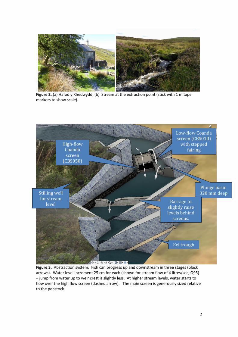
Figure 2. (a) Hafod y Rhedwydd, (b) Stream at the extraction point (stick with 1 m tape markers to show scale).
Figure 3. Abstraction system. Fish can progress up and downstream in three stages (black arrows). Water level increment 25 cm for each (shown for stream flow of 4 litres/sec, Q95) – jump from water up to weir crest is slightly less. At higher stream levels, water starts to flow over the high flow screen (dashed arrow). The main screen is generously sized relative to the penstock.
High-flow Coanda screen
(CBS050)
Low-flow Coanda screen (CBS010)
with stepped fairing
Plunge basin 320 mm deep
Barrage to slightly raise levels behind
screens.
Stilling well for stream
level measurements
Eel trough

3
Figure 4. Extraction limits as per the Abstraction Licence (no HEP extraction beyond Q95), screen flow rates and LowFlows simulation (split into October-March versus April-September).
Figure 5. The penstock has a tee-off to the house before continuing for another 475m towards the bottom of the valley.
4
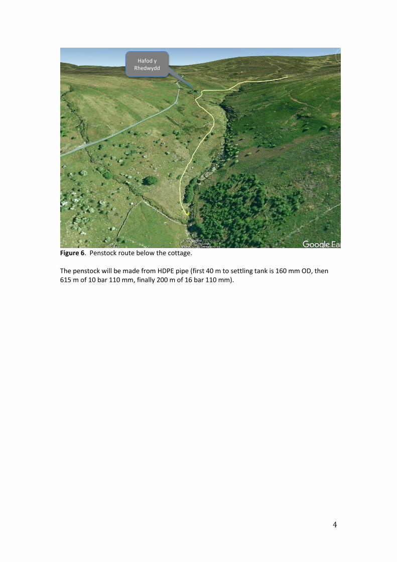
Figure 6. Penstock route below the cottage. The penstock will be made from HDPE pipe (first 40 m to settling tank is 160 mm OD, then 615 m of 10 bar 110 mm, finally 200 m of 16 bar 110 mm).
Hafod y Rhedwydd

5
Turbine and alternator choices In wet weather the cottage will use up to 9 kW to run electric radiators and immersion heater. In dry weather however the amount of water that may be extracted from the stream is severely limited (typically no extraction at all for 3 weeks each summer and <1 litre/sec for a further 4 weeks, when it may only generate 100 – 1000 Watts). The electricity in this peak holiday season is particularly valuable for running a UV water steriliser, fridge, lighting and satellite broadband dish, so good system efficiency is important. To provide reasonable efficiency over a 100:1 variation in power, the system will use a large and a small turbine:
wet weather turbine & alternator, up to 9-10 kW output
dry weather turbine and alternator, up to perhaps 1-2 kW output
Figure 7. Turbine hut layout. To ensure reliable operation over at least a 10:1 flow range, each turbine will have a main spear valve plus a much smaller one for low flow rates.
Figure 8. Turbine hut location.
4 m

6
Figure 9. Head loss curve and turbine speed (Hz for 2-pole alternator) at 0.49
runner jetV V
for Hartvigsen 75% Orange Spoon runners. These runners would satisfy the electricity meter specification of 50 Hz ±10% for up to 11 litre/sec without deviating from the 49% optimum efficiency point.
Figure 10. Nominal turbine shaft power assuming 85% turbine efficiency plus 80 W windage loss. Jet diameter is for a single jet. Hartvigsen Turgo runners:
“blue spoon” up to 14 mm jet (dry weather turbine)
“75% scale orange spoon” up to 21 mm jet (wet weather turbine)
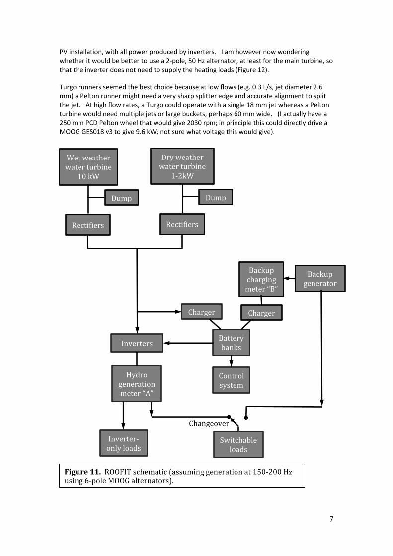
The turbine control system will adjust the spear valves to vary the extraction rate in response to power required and stream level (measured just below the screens); the house control system will disconnect loads above the generation capacity based on stream level. A small settling and de-aeration tank about 40m from the screens will contain a second level sensor to warn of any obstruction to flow due to screen blockage. The initial concept was for Turgo runners (Hartvigsen Hydro) driving 6-pole MOOG alternators at about 4-5000 rpm. At this stage MOOG appeared to be the only manufacturer of high efficiency (permanent magnet) high voltage alternators. The output would be rectified before transmission to the cottage; the cottage system (Fig. 11) would resemble a
7
PV installation, with all power produced by inverters. I am however now wondering whether it would be better to use a 2-pole, 50 Hz alternator, at least for the main turbine, so that the inverter does not need to supply the heating loads (Figure 12). Turgo runners seemed the best choice because at low flows (e.g. 0.3 L/s, jet diameter 2.6 mm) a Pelton runner might need a very sharp splitter edge and accurate alignment to split the jet. At high flow rates, a Turgo could operate with a single 18 mm jet whereas a Pelton turbine would need multiple jets or large buckets, perhaps 60 mm wide. (I actually have a 250 mm PCD Pelton wheel that would give 2030 rpm; in principle this could directly drive a MOOG GES018 v3 to give 9.6 kW; not sure what voltage this would give).
Changeover switch
Backup generator
Backup charging
meter “B”
Charger
Inverters
Charger
Battery banks
Hydro generation meter “A”
Inverter-only loads
Switchable loads
Control system
Wet weather water turbine
10 kW
Dry weather water turbine
1-2kW
Dump
Rectifiers
Dump
Rectifiers
Figure 11. ROOFIT schematic (assuming generation at 150-200 Hz using 6-pole MOOG alternators).
8
Charger
Turbine selector
Wet weather water turbine 10 kW 50 Hz
Dry weather water turbine 1-2 kW 200 Hz
Dump Dump
High power loads
Backup generator
Backup charge
meter “C”
Inverter
Charger
Battery bank
Inverter-only loads
Hydro generation meter “A”
Turbine control system
Cable to cottage
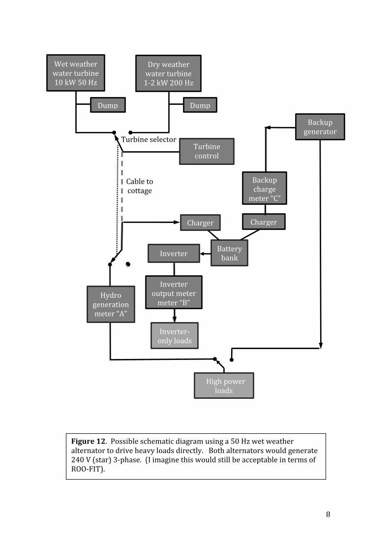
Figure 12. Possible schematic diagram using a 50 Hz wet weather alternator to drive heavy loads directly. Both alternators would generate 240 V (star) 3-phase. (I imagine this would still be acceptable in terms of ROO-FIT).
Inverter output meter
meter “B”
9
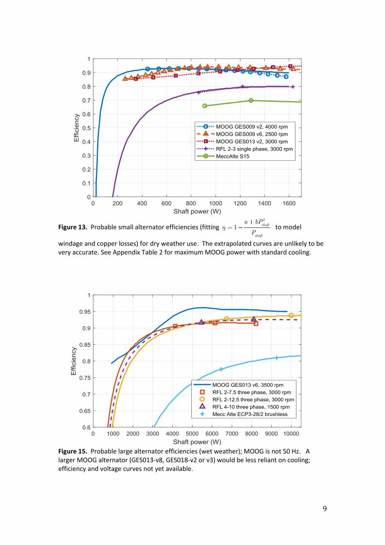
Figure 13. Probable small alternator efficiencies (fitting 2
1 shaft
shaft
a bP
P to model
windage and copper losses) for dry weather use. The extrapolated curves are unlikely to be very accurate. See Appendix Table 2 for maximum MOOG power with standard cooling.
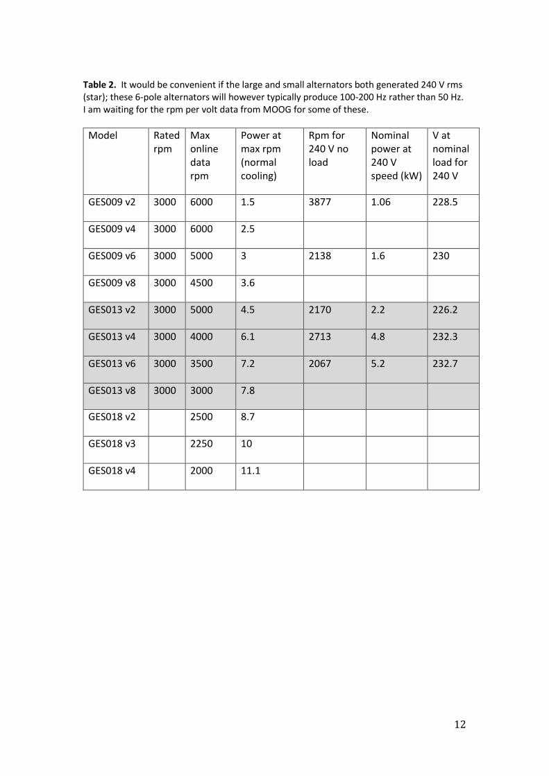
Figure 15. Probable large alternator efficiencies (wet weather); MOOG is not 50 Hz. A larger MOOG alternator (GES013-v8, GES018-v2 or v3) would be less reliant on cooling; efficiency and voltage curves not yet available.

10
Figure 16. RFL alternator voltages, including penstock head loss and transmission voltage
drop (4-core 10 mm2 cable) if operating at constant runner jetV V . This assumes no-load 400 V
phase-phase at 50 Hz; the alternator voltage-power curve is from their 4-pole data.
Conclusion Dry weather turbine: Turgo runner (37-off HH “blue spoon” to give 130 mm PCD,
3930 rpm) driving the MOOG GES009-v2 alternator (or possibly GES009-v4 if the
output voltage is suitable). For comparison, the GES009 v6 and GES013 v2 would
run at 2100 rpm if generating 240 V, needing a much larger turbine or a belt drive;
the increased power from these could however usefully complement the drop in
efficiency of the main alternator when powers fall to around 1500 W.
Wet weather turbine: Turgo runner (26-off HH “75% Orange spoon”, as figure 9 &
16) driving the RFL 2-12.5 alternator at 3000 rpm.

11
Appendix: Alternator manufacturers.
MOOG https://www.moog.com/products/alternators.html
RFL https://rflalternators.com/
Soga https://www.sogaenergyteam.com/alternators/
Mecc Alte https://www.meccalte.com/en/products
NSM http://www.nsmsrl.it/eng/prodotti.php
(a) MOOG
6-pole permanent magnet alternators. These do not have a cooling fan (they are mostly used for wind turbines) and the maximum output is very dependent on the airflow; I would need a small electric fan. The “rated power” is for 8-10 m/s air speed but this can be exceeded by 50% given enough cooling (unclear whether this is sensible in terms of life; the voltage would drop further as well). The very high efficiency should mean they need less cooling than ordinary alternators. Table 1. MOOG GES alternator rated powers.
I imagine that bearing replacement requires a MOOG service centre.
12
Table 2. It would be convenient if the large and small alternators both generated 240 V rms (star); these 6-pole alternators will however typically produce 100-200 Hz rather than 50 Hz. I am waiting for the rpm per volt data from MOOG for some of these.
Model Rated rpm
Max online data rpm
Power at max rpm (normal cooling)
Rpm for 240 V no load
Nominal power at 240 V speed (kW)
V at nominal load for 240 V
GES009 v2 3000 6000 1.5 3877 1.06 228.5
GES009 v4 3000 6000 2.5
GES009 v6 3000 5000 3 2138 1.6 230
GES009 v8 3000 4500 3.6
GES013 v2 3000 5000 4.5 2170 2.2 226.2
GES013 v4 3000 4000 6.1 2713 4.8 232.3
GES013 v6 3000 3500 7.2 2067 5.2 232.7
GES013 v8 3000 3000 7.8
GES018 v2 2500 8.7
GES018 v3 2250 10
GES018 v4 2000 11.1

13
(b) RFL RFL’s two-pole permanent magnet alternators offer the possibility of generating close to 50 Hz, 240 V AC which would allow heavy loads (radiators, immersion heater) to be driven directly (Fig. 13) rather than via a large inverter – probably a more reliable solution for the wet weather system. These alternators are single-bearing and would be easy to mount on the end of a two-bearing turbine shaft. Unfortunately the smallest RFL alternator (RF2-3, 3kVA frame size) is only available as a single-phase variant and the efficiency is not as good as their 3-phase machines. Table 3. Output parameters for the single-phase version of the RFL2-3 (some old stock still available in Australia; equivalent 3-phase (3 kVA) version not in production except for large orders).
FREQUENCY 50HZ
APPARENT POWER 1.6kVA RATED POWER 1.3kW VOLTAGE 230 EFFICIENCY @ 50% LOAD 75.5%
EFFICIENCY @ 75% LOAD 79.89% EFFICIENCY @ 100% LOAD 79.69%
The 3-phase models are more attractive - the RF2-12.5 (12.5 kVA, 10 kW) in particular would suit the wet weather system.
Table 4. 3-phase 2-pole alternator characteristics.
400/420 V - 50Hz - 3000RPM
MODEL
OPERATING TEMP: 40°C (Cont.) (ΔT = 40°C) Full (100% Load) Voltage
Transient THREE-PHASE MOTOR START
SHORT CIR.
EFFICIENCY THD Current Torque
kVA kW kVA A 1/2 3/4 Full % A N.m +%, -%
RF2-7.5 7.5 6 7.5 25 90.2 91.5 91.3 1.5 8.5 22.32 0.0/6.0
RF2-12.5 12.5 10 14 46.5 92.7 93.7 93.5 1.5 15.5 33.78 0.0/6.0
RF2-17.5 17.5 14 19 60 95.5 94.3 95.2 1.5 20 46.59 0.0/6.0

14
(c) Soga make multi-pole PM alternators but their data sheet does not show efficiency at part load or even the output voltage.
(i) Soga PMG 90, 8-pole output (kW).
(ii) Soga PMG 112, 12 pole.
(iii) Soga PMG140, 18 pole
15
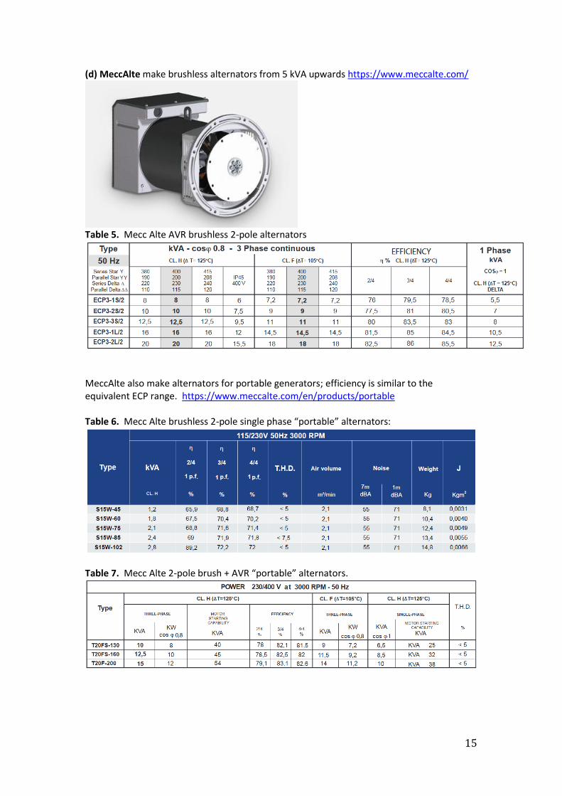
(d) MeccAlte make brushless alternators from 5 kVA upwards https://www.meccalte.com/
Table 5. Mecc Alte AVR brushless 2-pole alternators
MeccAlte also make alternators for portable generators; efficiency is similar to the equivalent ECP range. https://www.meccalte.com/en/products/portable Table 6. Mecc Alte brushless 2-pole single phase “portable” alternators:
Table 7. Mecc Alte 2-pole brush + AVR “portable” alternators.

16
(e) NSM http://www.nsmsrl.it/eng/prodotti.php , brochure http://www.nsmsrl.it/UserFiles/file/catgen.pdf?d=1557233759?time=now() make a wide range of alternators for portable generators.
Table 8. NSM 2-pole alternator examples
Model kVA (%) Phases Brush/brushless Cap/AVR
K80A 1.5 70.5 1 BL Cap
K80D 3 73 1 BL Cap
C112SB 10 79.5 1 BL Cap
KR80B 2.2 73.5 1 B AVR
CR112SB 10 80.5 1 B AVR
ZR100LB 10 85 3 B AVR
Table 9. NSM Permanent magnet generators
Recommended