Leitf
aden
für R
ettu
ngsd
iens
te P
KW ·
Fahr
zeug
e m
it al
tern
ative
n An
trieb
en
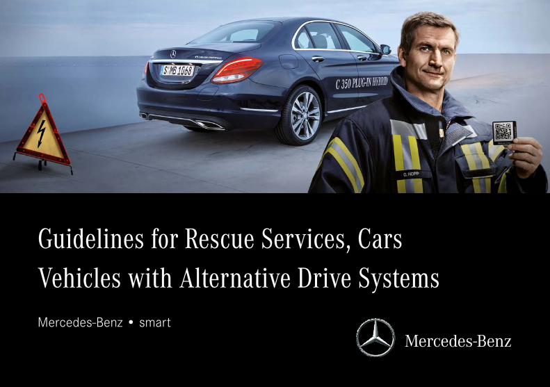
Guidelines for Rescue Services, Cars Vehicles with Alternative Drive SystemsMercedes-Benz • smart

Daimler AG · GSP/OR · D-70546 Stuttgart
Mercedes-Benz Service
Guidelines for Rescue Services, CarsVehicles with Alternative Drive Systems
Mercedes-Benz • smart

3Guidelines for Rescue Services, Cars | Vehicles with Alternative Drive Systems
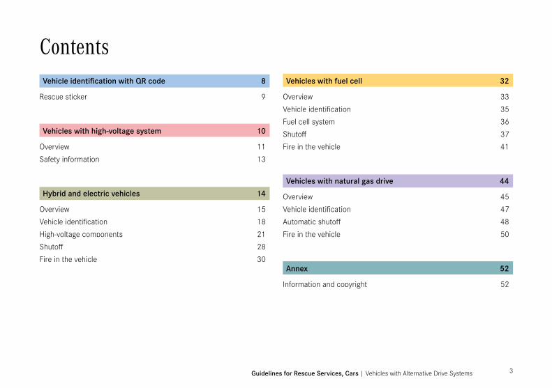
Vehicle identification with QR code 8
Rescue sticker 9
Vehicles with high-voltage system 10
Overview 11Safety information 13
Hybrid and electric vehicles 14
Overview 15Vehicle identification 18High-voltage components 21Shutoff 28Fire in the vehicle 30
Vehicles with fuel cell 32
Overview 33Vehicle identification 35Fuel cell system 36Shutoff 37Fire in the vehicle 41
Vehicles with natural gas drive 44
Overview 45Vehicle identification 47Automatic shutoff 48Fire in the vehicle 50
Annex 52
Information and copyright 52
Contents

4
Dear Reader,Vehicles with alternative drive systems are becoming increasingly popular. The number of them on our roads is rising steadily. Whether hybrids, battery-powered cars or vehicles with fuel cells, all have a number of special considerations which must be taken into account by rescue crews. The main components of these drive systems include high-voltage energy storage units and high-voltage assemblies. The handling of accident vehicles with these drive systems requires additional measures above and beyond the procedures for handling conventionally powered vehicles. This brochure is therefore intended to provide you with information concerning the safe handling or these vehicles by means of typical examples from your work environment.

5Guidelines for Rescue Services, Cars | Vehicles with Alternative Drive Systems
All the instructions and procedures described in this guide are to be understood to supplement the instructions and procedures for handling conventional vehicles. Broken-down vehicles and accident vehicles of this kind may only be towed by a professional breakdown service. Repair work on high-voltage systems may only be carried out at specially equipped workshops by specially trained personnel. This also applies if, during your work, high-voltage components are damaged or you discover other damage to these vehicles.
This guide does not claim to be exhaustive nor does it replace education and training courses for general and/or specialist knowledge on the handling of vehicles with alternative drive systems. We accept no responsibility for the topicality, correctness, completeness or quality of the information below. Any liability claims made against Daimler AG relating to either material or non-material damages arising from the use of the information provided are generally excluded, insofar as there is no demonstrable fault of an intentional or grossly negligent nature on the part of Daimler AG.
Daimler AGRetail Operations (GSP/OR)

6

7Guidelines for Rescue Services, Cars | Vehicles with Alternative Drive Systems
Further information
After-Sales PortalIn addition to this guide, supplemental information for rescue services and recovery crews is available in the After-Sales-Portal. The After-Sales Portal also provides access e.g. to the rescue data sheets (rescue cards) of all Mercedes-Benz cars. Other “Guidelines for Cars” are also available there containing detailed information. A set of guidelines specifically aimed at rescue services covers vehicles with conventional drive systems. The “Guidelines for Breakdown Services, Cars” are provided for vehicles with electric drives.
“Rescue Assist” mobile appThe rescue data sheets can also be accessed via the Daimler AG “Rescue Assist” mobile app. This is currently available for mobile devices with Android or Apple operating system. This app provides a QR code scanner for the rescue stickers (see p.9) as well as the ability to download the rescue data sheet for the vehicle in question in digital form by means of a list.
b Note
Access to the Mercedes-Benz After-Sales Portal:
http://aftersales.mercedes-benz.com
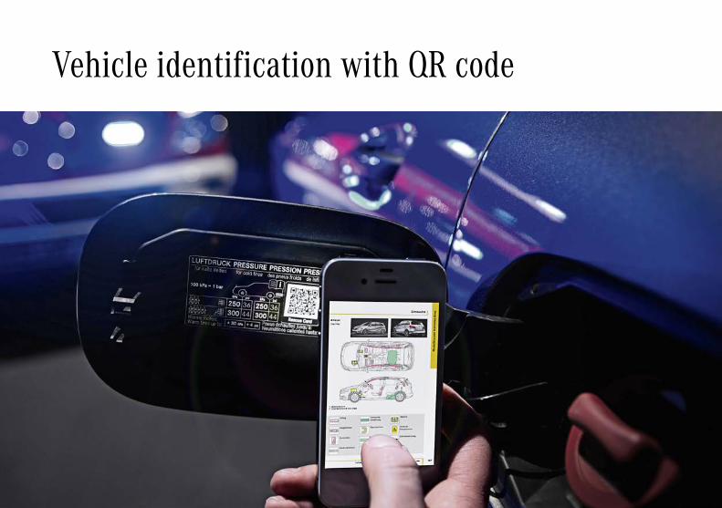
Vehicle identification with QR code
9Guidelines for Rescue Services, Cars | Vehicle identification with QR code
Rescue stickerQR code
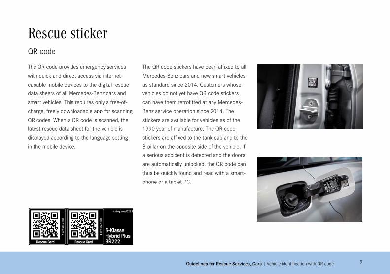
The QR code provides emergency services with quick and direct access via internet-capable mobile devices to the digital rescue data sheets of all Mercedes-Benz cars and smart vehicles. This requires only a free-of-charge, freely downloadable app for scanning QR codes. When a QR code is scanned, the latest rescue data sheet for the vehicle is displayed according to the language setting in the mobile device.
The QR code stickers have been affixed to all Mercedes-Benz cars and new smart vehicles as standard since 2014. Customers whose vehicles do not yet have QR code stickers can have them retrofitted at any Mercedes-Benz service operation since 2014. The stickers are available for vehicles as of the 1990 year of manufacture. The QR code stickers are affixed to the tank cap and to the B-pillar on the opposite side of the vehicle. If a serious accident is detected and the doors are automatically unlocked, the QR code can thus be quickly found and read with a smart-phone or a tablet PC.

10
Vehicles with high-voltage system
11
E-CELL HYBRID F-CELL
120-450 V
Guidelines for Rescue Services, Cars | Vehicles with high-voltage system
OverviewHigh-voltage systems in alternative drives
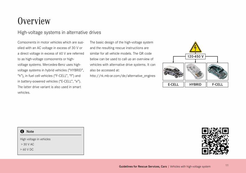
Components in motor vehicles which are sup-plied with an AC voltage in excess of 30 V or a direct voltage in excess of 60 V are referred to as high-voltage components or high-voltage systems. Mercedes-Benz uses high-voltage systems in hybrid vehicles (“HYBRID”, “h”), in fuel cell vehicles (“F-CELL”, “f”) and in battery-powered vehicles (“E-CELL”, “e”). The latter drive variant is also used in smart vehicles.
The basic design of the high-voltage system and the resulting rescue instructions are similar for all vehicle models. The QR code below can be used to call up an overview of vehicles with alternative drive systems. It can also be accessed at: http://rk.mb-qr.com/de/alternative_engines
b Note
High voltage in vehicles > 30 V AC > 60 V DC

12
b Note
The installation positions of the high-voltage components in specific ve-hicles can be found in the relevant rescue data sheets (see p.7).
OverviewHigh-voltage systems in alternative drives
The vehicles are distinguished according to the degree of electrification which can be achieved (HYBRID, E-CELL, F-CELL) as follows:• Electrical power requirements• Location and number of electric drive motors• Capacity and size of high-voltage battery• Voltage range of high-voltage system
The conventional 12 V on-board electrical system for supplying the 12 V components (lights, control units, comfort systems etc.) remains unchanged. The high-voltage system is electrically isolated from the vehicle ground and from the 12 V on-board system.
Depending on the vehicle model, the high-voltage system may include the following components in addition to the high-voltage battery and the electric motor:• Orange high-voltage lines• Power electronics with DC/DC converter• High-voltage PTC heating element• Electric refrigerant compressor• On-board charger with voltage converter• Fuel cell stack• Charging connection• High-voltage disconnect device
Descriptions of the individual components can be found below on pages 20-29 and 36.

13Guidelines for Rescue Services, Cars | Vehicles with high-voltage system
Safety informationHigh-voltage system
All high-voltage components are marked with an appropriate warning stickerto draw attention to the presence of a high voltage. The high-voltage lines supplying the components are orange.
Personal safety measures All contact with the high-voltage components in a vehicle should be avoided. This applies especially in the case of vehicles which have been involved in an accident or which have broken down due to a technical problem.
The following safety precautions should be observed: • Do not touch any open high-voltage lines
(orange) at the damaged point.• Do not cut any high-voltage lines
(orange).• Do not touch any high-voltage compo-
nents with damaged or broken housings, as these may always constitute an elec-trical hazard.
Avoid cutting or deforming the bodywork with rescue equipment in the vicinity of lines and components carrying high voltage. The locations of the high-voltage lines and the corresponding high-voltage components can be found in the relevant rescue data sheets for the vehicles (see p.7).

Hybrid and electric vehicles
15
4
13
2
Guidelines for Rescue Services, Cars | Hybrid and electric vehicles
OverviewHybrid vehicles
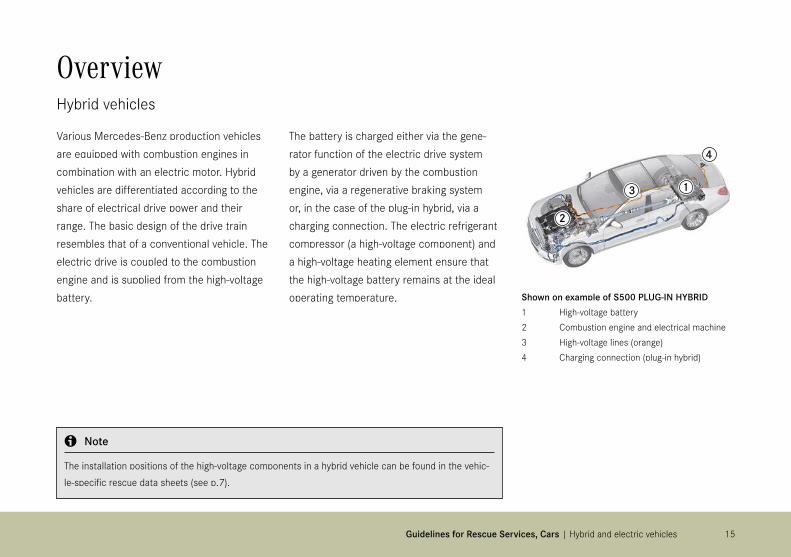
Various Mercedes-Benz production vehicles are equipped with combustion engines in combination with an electric motor. Hybrid vehicles are differentiated according to the share of electrical drive power and their range. The basic design of the drive train resembles that of a conventional vehicle. The electric drive is coupled to the combustion engine and is supplied from the high-voltage battery.
The battery is charged either via the gene-rator function of the electric drive system by a generator driven by the combustion engine, via a regenerative braking system or, in the case of the plug-in hybrid, via a charging connection. The electric refrigerant compressor (a high-voltage component) and a high-voltage heating element ensure that the high-voltage battery remains at the ideal operating temperature. Shown on example of S500 PLUG-IN HYBRID
1 High-voltage battery2 Combustion engine and electrical machine3 High-voltage lines (orange)4 Charging connection (plug-in hybrid)
b Note
The installation positions of the high-voltage components in a hybrid vehicle can be found in the vehic-le-specific rescue data sheets (see p.7).


17
4
1
3 2
Guidelines for Rescue Services, Cars | Hybrid and electric vehicles
OverviewElectric vehicles
Several Mercedes-Benz and smart vehicles are propelled purely by electrical power from a battery. The entire driving power is generated by one or more electric motors. The high-voltage battery delivers the energy necessary for the drive system. It is charged via the charging connection and via a regene-rative braking system.
As well as the electric drive motor, it also supplies or charges other assemblies, such as the electric refrigerant compressor (a high-voltage component), the high-voltage heating element and the 12 V battery. As in a conventional vehicle, the 12 V battery supplies the comfort systems (radio, interior illumination etc.), the lights, the control units and 12 V systems (such as the power steering).
Shown on example of smart fortwo coupé electric drive1 High-voltage battery2 Electrical machine and transmission3 High-voltage lines (orange)4 Charging connection
b Note
The installation positions of the high-voltage components in an electric vehicle can be found in the ve-hicle-specific rescue data sheets (see p.7).

18
Vehicle identificationHybrid and electric vehicles
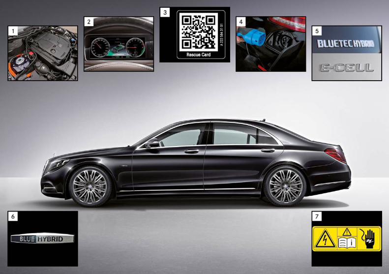
The model designations on the rear of the vehicle, such as “HYBRID”, “ED”, “h” (hybrid), “e” (electric vehicle, plug-in hybrid) or “E-CELL” indicate a vehicle with an alternative drive system. There are often additional inscriptions, e.g. on the fender. If there is no designation on the bodywork of the vehicle, information on the drive configuration can be found by looking inside the fuel filler door or at the B-pillar (QR code), in the owner's manual, at inscriptions on the instrument panel or the charge/fill level indicators in the instrument cluster.All the high-voltage components in the vehicle are identified by a warning label. The high-voltage lines are orange.
Typical identifying features for hybrid and electric vehicles are: • Orange high-voltage lines (1)• Charge indicator in the instrument cluster (2)• QR code for rescue crews (3)• High-voltage charging connection behind the fuel filler door (elec-
tric vehicle) or in the rear bumper (plug-in hybrid) (4)• Model plate on the right side of the trunk lid (5)• “BLUE HYBRID”, “electric drive” lettering on the right/left fen-
der/A-pillar (6)• High-voltage components with warning labels (7)• “Electric drive” symbol on the right and left B-pillars (smart only)• No exhaust system (electric vehicles only)• Owner's manual
b Note
The identifying features of specific vehicles can be found in the relevant rescue data sheets (see p.7).


21Guidelines for Rescue Services, Cars | Hybrid and electric vehicles
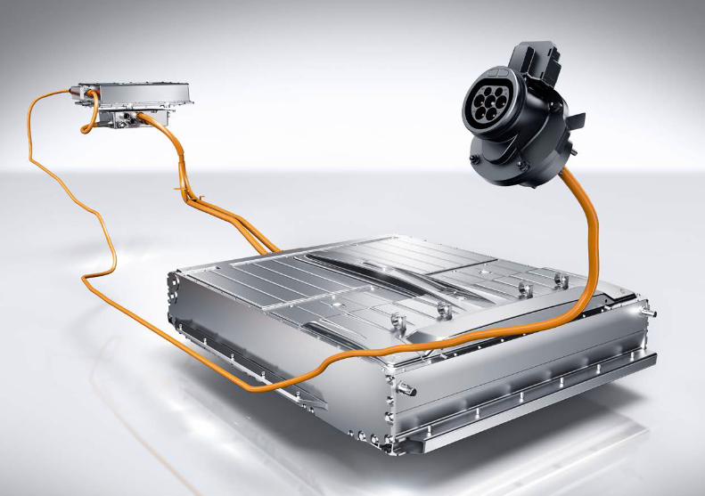
High-voltage componentsHigh-voltage battery
The high-voltage battery is the central accumulator which delivers the energy for the electrical machine of the drive system. The battery is charged by the generator of the combustion engine (HYBRID), by the fuel cells (F-CELL), via a regenerative braking system or via an external charging connection (plug-in hybrid or E-CELL).
In current Mercedes-Benz and smart vehicles with high-voltage system, only lithium-ion (Li-ion) battery cells are used as high-voltage batteries. According to the type and size of the Li-ion battery, the individual cells are combined into modules.
A cell voltage of approx. 3.6 V can be reached depending on the type and chemical composition of the individual cells. These are connected in series in order to produce the required operating voltage of the high-voltage system (up to 400 V).
Because the high-voltage battery is a safety-relevant component, it is installed in areas of the vehicle which are specially protected from the effects of a crash. Furthermore, various design measures (a protec-tive housing and frame) also protect the high-voltage battery against deformation and the intrusion of adjacent components.
23Guidelines for Rescue Services, Cars | Hybrid and electric vehicles
High-voltage componentsHigh-voltage battery
Each high-voltage battery features mechanical safety devices which are triggered in the event of an unusual increase in temperature and pressure inside the battery, and which are specifically designed to release the pressure.
Other safety measures protect the high-voltage battery against mechanical damage. Each high-voltage battery is monitored and cont-rolled by a battery management system (BMS).
The BMS checks the status of the high-voltage battery in all operating conditions. In case of a serious accident or a system error, the BMS switches the high-voltage battery terminals and the high-voltage sys-tem to a de-energized state by opening the battery contactors.
The high-voltage battery itself remains charged even after the high-vol-tage system has been shut off and discharged.
If the high-voltage battery is damagedBattery fluids are generally flammable, caustic and corrosive. Skin contact and inhalation of the vapors must therefore be avoided at all costs. The condition of the high-voltage battery must be monitored (e.g. for smoke development) because subsequent spontaneous ignition cannot be ruled out in the case of Li-ion batteries. It is recom-mended to request the assistance of a qualified expert in high-voltage systems in order to obtain an assessment of the electrical hazard and to arrange further procedures.

25Guidelines for Rescue Services, Cars | Hybrid and electric vehicles
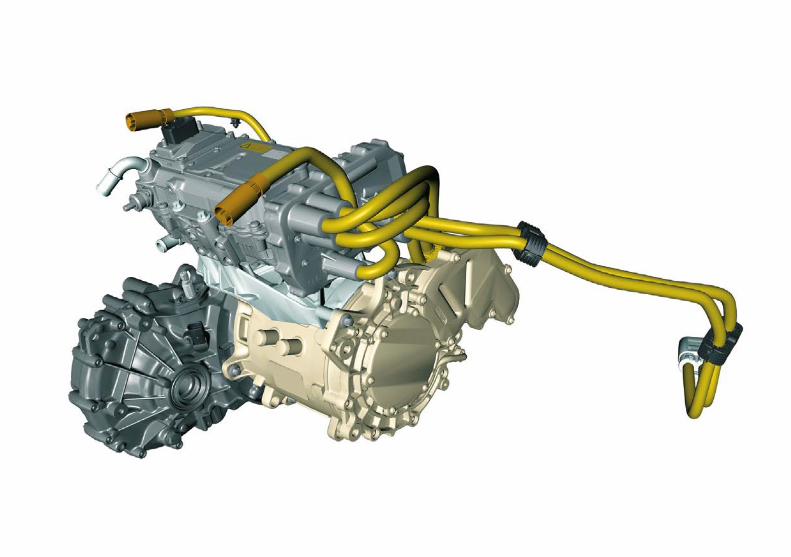
High-voltage componentsHigh-voltage drive system
The tasks of an electric motor in a hybrid vehicle are various. The high-voltage drive replaces the conventional function of a 12 V starter and recharges the high-voltage battery in braking phases (regenerative braking). While driving, the electric drive can assist the combustion engine or replace it entirely for short distances.
High-voltage linesAll the high-voltage components are connected to each other by a special line system. High-voltage lines are immediately identifiable by their larger cross section and their orange sheathing, and are clearly distinguishable from the wiring of the 12 V on-board electrical system. High-voltage lines are either 2-pole (direct voltage) or 3-pole (AC voltage) depending on their use.
The combination of high resistance to mechanical tensile loads with a high degree of flexibility means that high-voltage lines are extre-mely well protected against damage even in the event of a crash. The connections and plugs on the high-voltage components are cont-act-safe and are also monitored by a separate signal line (interlock). Another safety feature is the insulation monitoring of the high-voltage system. If a serious insulation fault is detected, the high-voltage system is shut off and discharged. The high-voltage lines have no electrical connection with the body of the vehicle. The feed and return lines are separate. There is a danger of electric shock only if both live conductors are touched. The high-voltage on-board electrical system is electrically isolated from the 12 V on-board system.

27Guidelines for Rescue Services, Cars | Hybrid and electric vehicles
High-voltage componentsOther high-voltage components
Power electronicsThe main task of the power electronics is to rectify the voltage and frequency so that the electric drive motor can be operated at its optimum operating point according to requirements. In some hybrid vehicles the conventional 12 V generator is omitted. The function of the generator is performed by a DC/DC converter which reduces the direct voltage of the high-voltage battery to the direct voltage required by the 12 V on-board electrical system.
On-board chargerTo charge the high-voltage battery from the electricity grid, an on-board charger is required. This regulates the charging power/ current and adjusts the type of voltage. In addition, the on-board charger esta-blishes the safety-relevant potential separation between the power network of a charging station and the high-voltage battery.
Electric refrigerant compressorThe drive motor must be isolated so that sufficient cooling output for the air conditioning can be provided when the vehicle, and therefore the combustion engine are stationary. This ensures that the high-vol-tage battery can be cooled independently and the climate control for the vehicle interior can operate independently. This is achieved by means of an electrically driven refrigerant compressor. In vehicles operated with electrical power only, cooling is always provided by an electric refrigerant compressor.
High-voltage PTC heating elementWhen driving under electrical power, the waste heat of the combustion engine is not available for heating the passenger compartment. The high-voltage PTC heating element therefore delivers the necessary heat in vehicles which can be driven without combustion engine.

28
Shown on example of S-Class HYBRID sedan
ShutoffHigh-voltage system
The recommended procedure for shutting off the HV system manually is as follows:1. Remove the ignition key. In vehicles with KEYLESS-GO, remove the
transmitter from the vehicle.2. Operate the relevant manual high-voltage disconnect device to
deactivate the HV on-board electrical system.3. Disconnect the 12 V battery (or batteries). (Further information
is available in the “Guidelines for Rescue Services, Cars, for Mercedes-Benz Vehicles”, see p.7)
In minor accidentsIn the case of minor accidents where the restraint systems have not been triggered or in the case of decommissioned vehicles, the high-voltage system is not automatically deactivated. Some vehicles also have functions which allow the high-voltage system to remain ac-tive when the ignition is off. This is the case, for example, in charging mode or in vehicles with programmable stationary climate control.
Before work is commenced on damaged vehicles or in the vicinity of high-voltage components, the high-voltage system has to be decativa-ted via the manual high-voltage disconnect device. In most cases the disconnect device is a 12 V separating point which can be operated by persons without specialist “high-voltage training”. The high-voltage energy store is isolated from the high-voltage energy system, but is not discharged.
29Guidelines for Rescue Services, Cars | Hybrid and electric vehicles
ShutoffHigh-voltage system
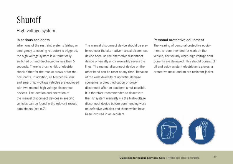
In serious accidentsWhen one of the restraint systems (airbag or emergency tensioning retractor) is triggered, the high-voltage system is automatically switched off and discharged in less than 5 seconds. There is thus no risk of electric shock either for the rescue crews or for the occupants. In addition, all Mercedes-Benz and smart high-voltage vehicles are equipped with two manual high-voltage disconnect devices. The location and operation of the manual disconnect devices in specific vehicles can be found in the relevant rescue data sheets (see p.7).
The manual disconnect device should be pre-ferred over the alternative manual disconnect device because the alternative disconnect device physically and irreversibly severs the lines. The manual disconnect device on the other hand can be reset at any time. Because of the wide diversity of potential damage scenarios, a direct indication of power disconnect after an accident is not possible. It is therefore recommended to deactivate the HV system manually via the high-voltage disconnect device before commencing work on defective vehicles and those which have been involved in an accident.
Personal protective equipmentThe wearing of personal protective equip-ment is recommended for work on the vehicle, particularly when high-voltage com-ponents are damaged. This should consist of oil and acid-resistant electrician's gloves, a protective mask and an arc-resistant jacket.

30
Fire in the vehicleHigh-voltage system
As in the case of conventional vehicles, fire in hybrid and electric vehicles can produce harmful fumes due to the burning materials, e.g. plastics. Rescue crews must wear the usual personal protective equipment.
Li-ion batteryLi-ion batteries are generally combustible due to their constituent ma-terials. The same applies for other energy stores, such as fuel tanks. The safety of the high-voltage batteries is further improved by additi-onal design measures on the battery housing and by the installation location of the batteries. Thanks to these safety measures, no greater risk of fire should be expected than for conventional vehicles.
The Li-ion battery as a whole and the individual battery cells feature mechanical safety devices which are triggered in the event of an (e.g. fire-related) increase in temperature and pressure inside the battery, and which help to deliberately degas the battery to release the pres-sure. Any burst of the Li-ion battery can therefore be almost entirely ruled out.
Use of extinguishing agentsGenerally, any available extinguishing agent may be used. If possible, fires should be extinguished with large quantities of water. Continuous dousing with water can cool the Li-ion battery enough to prevent the fire from spreading and to allow the Li-ion battery to burn out in a controlled manner.

31Guidelines for Rescue Services, Cars | Hybrid and electric vehicles
b Note
Further details about the towing and recovery of vehicles with electric drive systems are available in the “Guidelines for Breakdown Services, Cars” (see p.7).
Fire in the vehicleHigh-voltage system
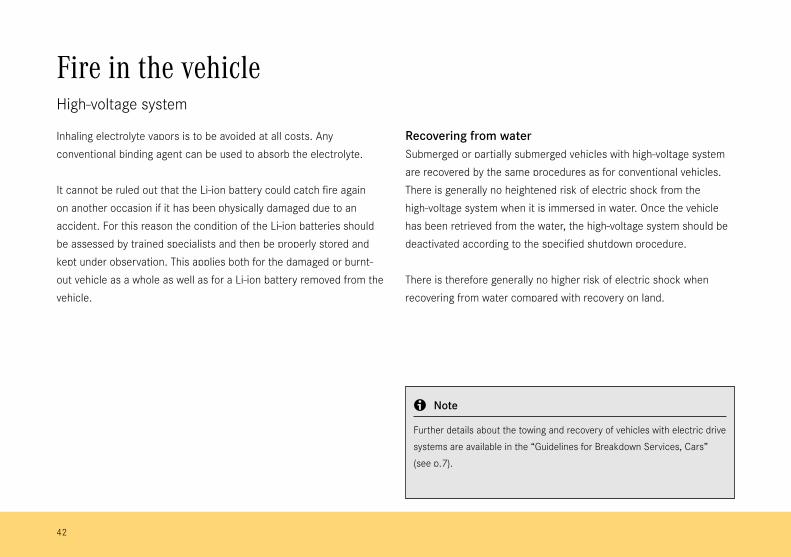
All contact with escaping battery fluid should be avoided as this could be irritant or corrosive depending on the type of battery. Inhaling electrolyte vapors is to be avoided at all costs. Any conventional binding agent can be used to absorb the electrolyte. It cannot be ruled out that the Li-ion battery could catch fire again on another occasion if it has been physically damaged due to an accident. For this reason the condition of the Li-ion batteries should be assessed by trained specialists and then be properly stored and kept under observation. This applies both for the damaged or burnt-out vehicle as a whole as well as for a Li-ion battery removed from the vehicle.
Recovering from waterSubmerged or partially submerged vehicles with high-voltage system are recovered by the same procedures as for conventional vehicles. There is generally no heightened risk of electric shock from the high-voltage system when it is immersed in water. Once the vehicle has been retrieved from the water, the high-voltage system should be deactivated according to the specified shutdown procedure.
There is therefore generally no higher risk of electric shock when recovering from water compared with recovery on land.

Vehicles with fuel cell

33
54
1
32
Guidelines for Rescue Services, Cars | Vehicles with fuel cell
OverviewFuel cell vehicles
Various Mercedes-Benz production vehicles are equipped with fuel cell systems for generating the drive energy. In the B-Class, for example, the entire fuel cell system is located on the vehicle floor. Instead of a conventional fuel tank there are cylindrical hydrogen tanks mounted on the vehicle floor in front of the rear axle.
The fuel cell stack is a highly efficient energy converter which generates the electrical energy required by the electric motor by means of an electrochemical process. The high-voltage battery is housed in the trunk floor. It stores the electrical energy generated in the fuel cell system and recovered from regenerative braking.
Shown on example of B-Class F-CELL1 Fuel cell stack2 Electrical machine and transmission3 High-voltage lines (orange)4 Hydrogen tanks5 High-voltage battery
b Note
The installation positions of the high-voltage components in a fuel cell vehicle can be found in the ve-hicle-specific rescue data sheets (see p.7).
34
Vehicle identificationFuel cell vehicles
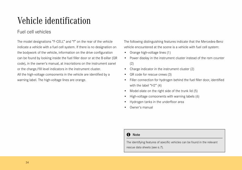
The model designations “F-CELL” and “f” on the rear of the vehicle indicate a vehicle with a fuel cell system. If there is no designation on the bodywork of the vehicle, information on the drive configuration can be found by looking inside the fuel filler door or at the B-pillar (QR code), in the owner's manual, at inscriptions on the instrument panel or the charge/fill level indicators in the instrument cluster. All the high-voltage components in the vehicle are identified by a warning label. The high-voltage lines are orange.
The following distinguishing features indicate that the Mercedes-Benz vehicle encountered at the scene is a vehicle with fuel cell system: • Orange high-voltage lines (1)• Power display in the instrument cluster instead of the rpm counter
(2) • Charge indicator in the instrument cluster (2)• QR code for rescue crews (3)• Filler connection for hydrogen behind the fuel filler door, identified
with the label “H2” (4)• Model plate on the right side of the trunk lid (5)• High-voltage components with warning labels (6)• Hydrogen tanks in the underfloor area • Owner's manual
b Note
The identifying features of specific vehicles can be found in the relevant rescue data sheets (see p.7).


36
Fuel cell systemOverview of components
Fuel cell stackThe fuel cell stack is the heart of the fuel cell drive system. The stack is the energy converter in which electrical energy is generated from the oxygen in the air and the separately supplied hydrogen. The electricity generated is fed into a high-voltage battery and thus supplies the drive system as well as all the other electrical systems in the vehicle.
Tank systemIn the aluminum or carbon fiber hydrogen tanks, gaseous hydrogen is stored at pressures of up to 700 bar. The tanks are filled at hydrogen refueling stations. The refueling process itself is not substantially different from modern refueling with gasoline or diesel.
Fuel cell stack
Hydrogen tanks

37Guidelines for Rescue Services, Cars | Vehicles with fuel cell
ShutoffHigh-voltage system
Before commencing any rescue action, make sure that the high-voltage and fuel systems in vehicles with fuel cells are deactivated.
The high-voltage system operates with voltages of up to several hundred volts. In a serious accident where a restraint system has trig-gered, this is automatically switched off and discharged in less than 5 seconds. However, the battery itself remains charged even after the high-voltage system has been shut off.
The automatic shutoff means that generally there is no increased danger of electric shock to the occupants and rescue crews. The high-voltage system is isolated from the vehicle body and other electri-cal circuits, i.e. it is not connected to the bodywork.
b Note
The automatic shutoff of the high-voltage system is linked to the triggering of the restraint systems. Therefore, if an airbag or an emergency tensioning retractor has been triggered, it can be assumed that the high-voltage sys-tem has been shut off.

38
Manual high-voltage disconnectShown on example of B-Class F-CELL Tourer1 Location on top of refrigerant compressor2 Pull up locking ring 3 Unplug connector
ShutoffHigh-voltage system
In addition to the automatic deactivation of the high-voltage system, vehicles with fuel cell also feature a manual and an alternative manual high-voltage disconnect function similar to hybrid and battery-powered vehicles.
Because of the wide diversity of potential damage scenarios, a direct indication of the voltage remaining in a high-voltage system after an accident is not possible.
The location and operation of the manual high-voltage disconnect device and the alternative manual high-voltage disconnect device can be found in the relevant rescue data sheets (see p.7).

39Guidelines for Rescue Services, Cars | Vehicles with fuel cell
ShutoffHydrogen system
The hydrogen system operates with normal pressure of up to 700 bar and gas temperature of 15° C. If the gas temperature exceeds 15° C the storage pressure might increase up to 875 bar. This could happen after refueling. If an accident triggers a restraint system, all the gas valves are closed mechanically in order to halt the gas supply.
Overpressure safeguardIn the event of a malfunction of the hydrogen pressure regulator in the fuel system, the pressure relief valve opens and enables the controlled release of the hydrogen via the vent line into the atmosphere. The pressure relief valve opens at pressures above approx. 16 bar. The protective cap on the outlet of the vent line is separated by the pressure of the escaping hydrogen.
Overtemperature safeguardEach hydrogen tank is fitted with a shutoff valve with integrated overtemperature safeguard. The overtemperature safeguard prevents the hydrogen tanks from bursting under the effects of heat. At temperatures > 110 °C the overtemperature safeguard opens and allows a controlled escape of the hydrogen via the vent line.

40
HHydrogenWassersto�
2
ShutoffHydrogen system
Vent line for high-pressure tanksThe vent line is specifically passed away from the vehicle. The outlet is sealed with a protective cap. The venting of the gases can produce large jets of flame for short periods. These may occur several times in succession.
Hydrogen flames are colorless so it may not be possible to detect them under certain circumstances. A blown protective cap on the out-let can be an indication that hydrogen has been or is being vented into the atmosphere via the vent line. Listen for any loud noises of esca-ping gas (“hissing”) caused by the gas venting under high pressure.
b Note
Be particularly careful with venting gas in vehicles lying on their roof.

41Guidelines for Rescue Services, Cars | Vehicles with fuel cell
Fire in the vehicleHigh-voltage system
As in the case of conventional vehicles, fire in fuel cell vehicles can produce harmful fumes due to the burning materials, e.g. plastics. Rescue crews are advised to wear the usual personal protective equipment.
Li-ion batteryLi-ion batteries are generally combustible due to their constituent materials. The same applies for other energy stores, such as fuel tanks.Li-ion batteries are protected by safety measures, e.g. the shutoff of the high-voltage system in the event of a serious accident, as well as by design measures on the battery housing and by the installation location of the batteries. Thanks to these safety measures, no greater risk of fire is expected than for conventional vehicles.
Use of extinguishing agentsGenerally, any available extinguishing agent may be used. If possible, fires should be extinguished with large quantities of water. Continuous dousing with water can cool the Li-ion battery enough to prevent the fire from spreading and to allow the Li-ion battery to burn out in a controlled manner.All contact with escaping battery fluid should be avoided as this could be irritant or corrosive depending on the type of battery.
42
b Note
Further details about the towing and recovery of vehicles with electric drive systems are available in the “Guidelines for Breakdown Services, Cars” (see p.7).
Fire in the vehicleHigh-voltage system
Inhaling electrolyte vapors is to be avoided at all costs. Any conventional binding agent can be used to absorb the electrolyte.
It cannot be ruled out that the Li-ion battery could catch fire again on another occasion if it has been physically damaged due to an accident. For this reason the condition of the Li-ion batteries should be assessed by trained specialists and then be properly stored and kept under observation. This applies both for the damaged or burnt-out vehicle as a whole as well as for a Li-ion battery removed from the vehicle.
Recovering from waterSubmerged or partially submerged vehicles with high-voltage system are recovered by the same procedures as for conventional vehicles. There is generally no heightened risk of electric shock from the high-voltage system when it is immersed in water. Once the vehicle has been retrieved from the water, the high-voltage system should be deactivated according to the specified shutdown procedure.
There is therefore generally no higher risk of electric shock when recovering from water compared with recovery on land.

43Guidelines for Rescue Services, Cars | Vehicles with fuel cell
Fire in the vehicleHydrogen system
HydrogenHydrogen gas has a density of approx. 0.09 kg/m³ under standard conditions and is therefore lighter than air. When mixed with air in ranges from 4 vol% to 77 vol%, hydrogen gas forms an ignitable mixture. A mixture with a hydrogen content of up to 10.5 vol% is heavier than air and sinks to the ground. This mixture is ignitable until diluted to less than 4 vol% hydrogen. A hydrogen flame is virtually invisible in daylight. Escaping hydrogen gas is not odorized and is therefore entirely odorless and colorless.
Use of extinguishing agentsHydrogen is a Class C gas according to European standard EN2 for “Flammable materials of various kinds”. All Class C extinguishing agents can be used, such as ABC powder extinguisher. Generally, firefighting should not be commenced until the gas supply has been suppressed in order to avoid creating an explosive gas/air mixture.
44
Vehicles with natural gas drive

45Vehicles with natural gas drive | Vehicles with natural gas drive
OverviewVehicles with natural gas drive
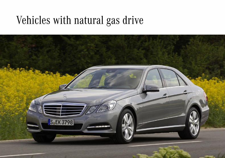
Various Mercedes-Benz production vehicles are equipped with engines powered by gasoline and natural gas. The engine can be operated either with natural gas (c or CNG = compressed natural gas) or with gasoline. The operating mode can be selected either manually by the driver or automatically depending on the vehicle model. The selection is automatic when one of the two fuels is exhausted.
In addition to the conventional fuel tank, gas cylinders made of high-strength steel or plastic composite material are also installed. These may be located in the spare wheel well and behind the rear seats in the trunk.
The natural gas is stored in these cylinders at a normal pressure of up to 200 bar.
The gas cylinders are filled via a filling connection located beside the gasoline tank filler neck behind the lengthened fuel filler flap.
b Note
The installation positions of the relevant components of the natural gas drive system can be found in the vehicle-specific rescue data sheets
(see p.7).
46
Vehicle identificationVehicles with natural gas drive
The model designation “NATURAL GAS DRIVE”, “c” or “NGT” on the rear of the vehicle indicates a vehicle with natural gas drive. If there is no designation on the bodywork of the vehicle, information on the drive configuration can be found by looking inside the fuel filler door or at the B-pillar (QR code), in the owner's manual, at inscriptions on the instrument panel or the fill level indicators in the instrument cluster.
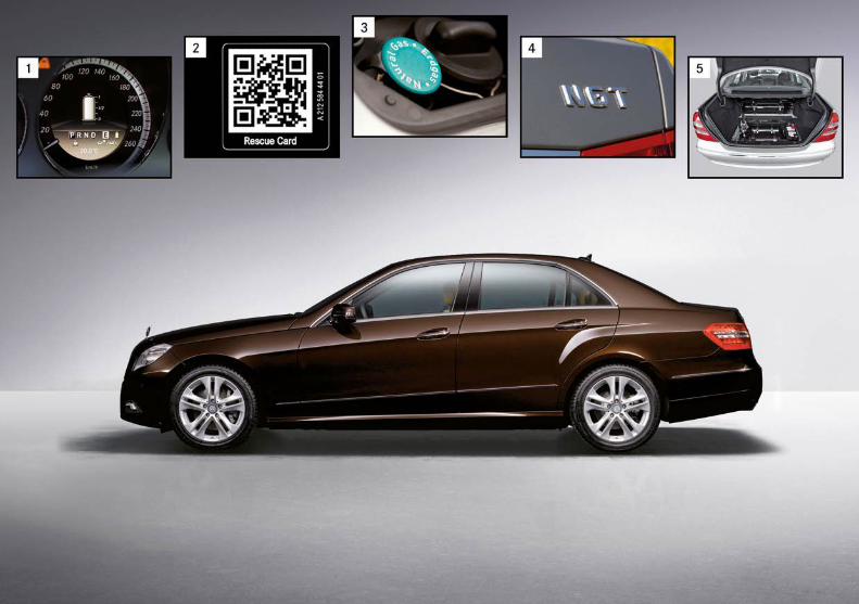
The following distinguishing features indicate that the Mercedes-Benz vehicle encountered at the scene is a vehicle with a natural gas drive system:• CNG/NGT/NGD lettering in the instrument cluster and separate
range indicators for gasoline and natural gas operation (1)• QR code for rescue crews (2)• Filler neck for natural gas beside the conventional fuel tank filler
neck (3)• “NATURAL GAS DRIVE”, “c” or “NGT” lettering on the right side of
the trunk lid (4)• Gas cylinders in the underfloor area and/or in the spare wheel
well (5)
b Note
The identifying features of specific vehicles can be found in the relevant rescue data sheets (see p.7).

48
Automatic shutoffNatural gas system
The natural gas system operates with pressures of up to 260 bar. If an accident triggers a restraint system, all the gas valves are closed immediately in order to halt the gas supply to the engine. In terms of its properties, the natural gas itself is much less dangerous than, for example, gasoline. A natural gas/air mixture has only a very narrow ignition range, an ignition temperature three times higher than gasoline, and it is lighter than air. For this reason, no greater risk of fire is expected than for conventional vehicles if all the appropriate safety precautions are complied with.
Safety shutoff of gas cylindersIf the airbag control unit detects that the vehicle is involved in a collision, the gas cylinder safety shutoff function is triggered. This crash signal shuts off both the natural gas and gasoline injection systems.
The gas cylinders are mounted in stable fixtures. Each individual gas cylinder is checked at a test pressure of 300 bar, and each one has a burst pressure rating of more than 600 bar.

49Vehicles with natural gas drive | Vehicles with natural gas drive
Automatic shutoffNatural gas system
Each gas cylinder is fitted with a safety armature. When the vehicle is parked, running on gasoline or involved in an accident, the cylinders are automatically locked by the electromagnetic shutoff valve. The thermally activated safety valves with fuses (range 110 ±10°C), rupture disks and flow rate limiters prevent the gas cylinders from bursting. In the event of overtemperature, the fuses are tripped to eject the gas in a controlled manner.

50
Fire in the vehicleNatural gas system
Natural gasIn terms of its properties, natural gas itself is much less dangerous than gasoline, having e.g. only a very narrow ignition range (approx. 4-16.5 vol%) and an ignition temperature three times higher than gasoline (approx. 640°C), and being lighter than air (density ratio of natural gas/air approx. 0.6).
Natural gas is usually colorless and odorless. To allow enable natural gas to be detected, an odorant is added which is responsible for the typical gas odor.
The following should be observed in case of escaping gas:• Avoid ignition sources• Switch off the engine• Measure the gas concentration• Let the gas escape and ensure adequate ventilation if necessary
(blow the gas away)
B Warning
There is a risk of explosion from natural gas escaping in an uncontrolled manner!

51Vehicles with natural gas drive | Vehicles with natural gas drive
Fire in the vehicleNatural gas system
The thermofuses of the gas tanks are activated at a temperature of approx. 110°C ± 10°C. Note the discharge directions of the gas tanks in vehicles which are lying on their side or on their roof because controlled jets of flame can occur when the thermofuses are triggered.
Conventional firefighting methods should not be used until all the natural gas has escaped. If necessary, use ventilation to help the natural gas to escape.
The venting of the gases can produce large jets of flame for short periods. These may occur several times in succession. Listen for any loud hissing noises caused by the gas venting under high pressure.
Extinguishing agentNatural gas is a Class C gas according to European standard EN2 for “Flammable materials of various kinds”. All Class C extinguishing agents can be used, such as ABC powder extinguisher. Generally, firefighting should not be commenced until the gas supply has been suppressed in order to avoid creating an explosive gas/air mixture.

52
Product portfolioYou can also find comprehensive information about our complete product portfolio on our Internet portal: Link: http://aftersales.mercedes-benz.com
Questions and suggestionsIf you have any questions or suggestions concerning this product, please write to us. E-mail: [email protected]
© 2015 by Daimler AG This document, including all its parts, is protected by copyright. Any further processing or use requires the previous written consent of Daimler AG, Department GSP/OR, D-70546 Stuttgart. This applies in particular to reproduction, distribution, alteration, translation, microfilming and storage and/or processing in electronic systems, including databases and online services.
Information and copyright

Leitf
aden
für R
ettu
ngsd
iens
te P
KW ·
Fahr
zeug
e m
it al
tern
ative
n An
trieb
en
Daimler AG, GSP/OR, D-70546 Stuttgart
Recommended