GNURadio-FFTS DocumentationRelease 2.7
Simon Olvhammar
May 15, 2016


Contents
1 Introduction 31.1 Acknowledgements . . . . . . . . . . . . . . . . . . . . . . . . . . . . . . . . . . . . . . . . . . . 31.2 Personal background . . . . . . . . . . . . . . . . . . . . . . . . . . . . . . . . . . . . . . . . . . . 4
2 Ettus X310 and Gnuradio 52.1 The Ettus USRP . . . . . . . . . . . . . . . . . . . . . . . . . . . . . . . . . . . . . . . . . . . . . 52.2 PCIe interface . . . . . . . . . . . . . . . . . . . . . . . . . . . . . . . . . . . . . . . . . . . . . . 62.3 Sampling rates . . . . . . . . . . . . . . . . . . . . . . . . . . . . . . . . . . . . . . . . . . . . . . 62.4 GNU Radio . . . . . . . . . . . . . . . . . . . . . . . . . . . . . . . . . . . . . . . . . . . . . . . . 72.5 Interfacing with JTAG . . . . . . . . . . . . . . . . . . . . . . . . . . . . . . . . . . . . . . . . . . 8
3 Spectrometer Manual 93.1 USRP, Computer and Server initialization . . . . . . . . . . . . . . . . . . . . . . . . . . . . . . . . 93.2 Specifications . . . . . . . . . . . . . . . . . . . . . . . . . . . . . . . . . . . . . . . . . . . . . . . 103.3 Recommended bandwidths [MHz] . . . . . . . . . . . . . . . . . . . . . . . . . . . . . . . . . . . . 103.4 List of commands . . . . . . . . . . . . . . . . . . . . . . . . . . . . . . . . . . . . . . . . . . . . 113.5 Effective bandwidth and offsets . . . . . . . . . . . . . . . . . . . . . . . . . . . . . . . . . . . . . 11
4 Code explanation 134.1 USRP_start.sh . . . . . . . . . . . . . . . . . . . . . . . . . . . . . . . . . . . . . . . . . . . . . . 134.2 Server.py . . . . . . . . . . . . . . . . . . . . . . . . . . . . . . . . . . . . . . . . . . . . . . . . . 134.3 Measurement.py . . . . . . . . . . . . . . . . . . . . . . . . . . . . . . . . . . . . . . . . . . . . . 144.4 Receiver.py . . . . . . . . . . . . . . . . . . . . . . . . . . . . . . . . . . . . . . . . . . . . . . . . 144.5 Analyze.py . . . . . . . . . . . . . . . . . . . . . . . . . . . . . . . . . . . . . . . . . . . . . . . . 154.6 Finalize.py . . . . . . . . . . . . . . . . . . . . . . . . . . . . . . . . . . . . . . . . . . . . . . . . 154.7 Improvements and other toughts . . . . . . . . . . . . . . . . . . . . . . . . . . . . . . . . . . . . . 15
5 FPGA implementation using RFNoC 175.1 RFNoC . . . . . . . . . . . . . . . . . . . . . . . . . . . . . . . . . . . . . . . . . . . . . . . . . . 175.2 GNURadio-FFTS RFNoC modification . . . . . . . . . . . . . . . . . . . . . . . . . . . . . . . . . 17
6 Results and discussion 19
7 References 21
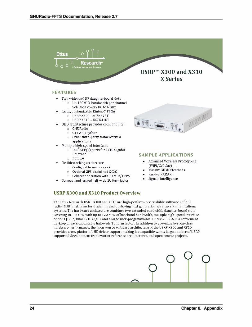
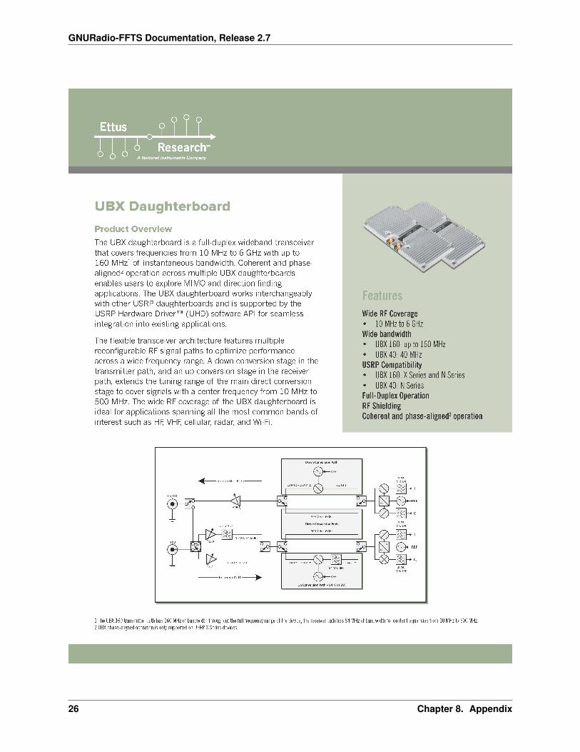
8 Appendix 238.1 Ettus USRP X310 Data sheet . . . . . . . . . . . . . . . . . . . . . . . . . . . . . . . . . . . . . . 238.2 UBX-160 Daughterboard Data sheet . . . . . . . . . . . . . . . . . . . . . . . . . . . . . . . . . . . 23
i

9 Indices and tables 29
ii

GNURadio-FFTS Documentation, Release 2.7
Contents:
Contents 1
GNURadio-FFTS Documentation, Release 2.7
2 Contents

CHAPTER 1
Introduction
Software defined radio (SDR) was initially introduced by J.Mitola in 1995 [1]. It can be described as a radio thatcan change it’s physical equivalance through modifications in software. Since the work of Mitola SDRs has obtaineda key role in the development of new radio systems [2] which is in part motivated by the high flexibility and costeffectiveness that a digital solution yields [3]. The main supplier for SDRs today is the Ettus Research and NationalInstruments company (NI) providing the Universal Software Radio Peripheral (USRP) as the SDR product line [4].The SDR platform essentially provides a front-end for discretization of the signal as well as a Digital Down Donverter(DDC) chain through the usage of a Field-Programmable Gate Array (FPGA) [5]. The strength and flexibility of theUSRP is exposed when combined with software interfaces such as GNU Radio and NI-LabView, providing digitaldomain signal processing [6].
Studies of microwave spectral emission from different kinds of molecules is fundamental in the fields of Astronomyand Aeronomy. Hydrogen is the most common substance in the Universe thus making the transition at 21 cm of centralinterest to astronomers, e.g. for studies of galactic spiral arms. Microwave radiation is also abundant from differentgases in the atmosphere, both CO, O2, H2O and O3 exhibit rotational transitions below 150 GHz thus providing a wayto study the concentration and distribution of these gases in the atmosphere [7]. The technique most commonly used,for these kinds of studies and observations is Dicke-switching, first introduced by physicist Robert H. Dicke. Dicke-switching is a method that eliminates gain variations in receiver systems by rapidly comparing signals, often labelledsignal and reference. The reference can be a source of known temperature, another part of the sky or by defining areference through mixer tuning. The techniques are referred to as load, sky and frequency-switching respectively [8].
This documentation briefly explains how a general purpose Dicke-switched Fast Fourier Transform Spectrometer(FFTS) can be achieved using Software Defined Radio (SDR) platforms, i.e. the Ettus USRP x310 interfaced with thesignal processing toolkit GNU Radio. However the main function of this documentation is to act as a informationalsource and usage manual for employees at Onsala Space Observatory (OSO) using the two GNURadio-FFTSs on thesite. For that purpose it is mainly the section “Manual” and “USRP and GNURadio” that is relevant.
1.1 Acknowledgements
First of all I would like to thank Gunnar Elgered for making this project possible. I would also like to thank LarsPetersson and Peter Forkman for supervising the project and providing me with wonderful insights and supporting meat all times. The SALSA system has been a inspirational source throughout this project and I have Eskil Varenius tothank for that. Mikael Lerner has played a fundemental role in integrating the spectrometer in existing systems andit’s now continous usage would not have happend without him. The spectrometer is fully integrated in his softwarepackage BIFROST, providing a truly great interface for Radiometers in Sweden and around the world.
3

GNURadio-FFTS Documentation, Release 2.7
1.2 Personal background
I am a bachelor student at Chalmers University of Technology in Sweden and have been, part time, developing a newspectrometer solution for Radio Astronomy and Aeronomy. I am currently pursuing a degree in Master of Wirelessand Space Engineering and eventually a Phd.
4 Chapter 1. Introduction

CHAPTER 2
Ettus X310 and Gnuradio
The section explains the Ettus USRP architechture, the GNURadio toolkit and deals with topics such as samplingrates and master clock rates. Installation instructions for e.g GNURadio can also be found. Most of the followinginformation can be applied to other Ettus USRP devices.
2.1 The Ettus USRP
Ettus Research and the National instruments company provides a broad product line of SDR platforms with e.g dif-ferent frequency coverage and bandwidths [4]. The Ettus USRP X3x0 series is currently the most high performingplatform and would be the most suitable for radio systems with high demands on bandwidth and accuracy. Theprovided General Purpose Input Output (GPIO) interface in the x3x0 series also makes implementations of Dicke-switching an easier task, and as we shall see is fundamental for the FFTS described here. A general USRP architectureis provided in the figure below, specifics may vary depending on the model [5].
Fig. 2.1: A general Ettus USRP architecture demonstrating the signal chain and processing performed. Based on theEttus N210 with daughterboard WBX [5].
5
GNURadio-FFTS Documentation, Release 2.7
The first part of the receiver (RX) chain consist of a fundamental Low Noise Amplifier (LNA) with variable atten-uation exposed in software e.g GNURadio. The signal is further modulated into inphase and quadrature signals Iand Q. Analog and Digital (A/D) converters handles the discretization of the RF providing a bandwidth determinedby the daughterboard i.e the front-end of the Ettus USRP [2]. The onboard FPGA down converts the signal by anDigital Down Converter (DDC) implementation providing fine frequency tuning and filters for decimation. The datais subsequently exposed to the host computer through Ethernet or PCIe interfaces.
2.2 PCIe interface
The PCIe interface provides high data throughput together with low latency, where the latter is a important part forDicke-switched purposes due to the importance of deterministic timings. However the 10 Gbit ethernet interfaceprovides higher throughput.
2.2.1 Installation
The latest PCIe driver can be downloaded here. Follow the instructions at the site to install the driver. This simplyinvolves unpacking the software and running the install script followed by a reboot. Se the manual on how to disableand enable the PCIe drivers. Navigate to http://files.ettus.com for older versions of the driver.
2.3 Sampling rates
The x3x0 series delivers up to 200 M samples/s (I/Q), thus your host computer might have trouble keeping up to speed.Overflow, lost samples, is indicated by a an O in the terminal and is an indication that there is a bottle neck at yourhost. Several things can be done to address this issue.
First of all is to check that your hardware is up to speed. Check the CPU load, RAM usage and not least the harddrive.A mechanical drive would allow a sample rate up to about 30 Mhz of I/Q sampling depending on the harddrive. Theother option would be to use a SSD and it can get you alot higher, however I experienced quite alot of performanceissues when running under Linux, with write speeds way below the specifications. I eventually abandoned the SSDand right now I am using Ramdisk, which in theory should have no problem whatsoever for a complex sample rate of200Mhz (800MB/s).
Other host side improvements that can be done is to expand the socket buffers, setting the governors for your CPU torun at maximum performance and several other parameters. More information and instructions on this can be foundhere.
If perfomance issues is still a problem go back to the base of your application and check for issues there. There is alsoanother option, which is FPGA programming. Go to this section for more information.
2.3.1 Sampling rate decimations
There are several half band filters incorporated in the Ettus X310 device and some decimations may result in all ofthem not being activated. Those decimations are the uneven ones. For example a sampling frequency of 50 Mhz = 200Mhz / 4 will have all the half band filters activated.
2.3.2 Master Clock Rates
The Ettus x310 currently support three different Master Clock Rates; 200Mhz (Default), 184.32Mhz and 120Mhz. Inpractice this means that other even sampling rate decimations can be achieved, allowing for better filter trade-off. TheMaster Clock Rate can be set in the GnuRadio application, see Code explanation for details.
6 Chapter 2. Ettus X310 and Gnuradio

GNURadio-FFTS Documentation, Release 2.7
2.4 GNU Radio
The software interface GNU Radio performs signal processing through the use of dedicated blocks, e.g. infiniteimpulse response filters (IIR) or FFT calculations, designed in C++. The signal processing blocks can be linked toperform the desired computations in the GNU Radio Companion (GRC) Graphical User Interface (GUI) or directlythrough the use of a programming language such as Python. GNU Radio provides a vast library of signal processingblocks that can easily be modified to custom specifications. GNU Radio is also published under the GNU GeneralPublic Licence (GPL), thus making it free to use and modify.
2.4.1 Installation
From my experience I found that the easiest way to get a USRP device up and running with Gnuradio is to use MarcusLeech installation script. It will install both the Ettus UHD software (to interface with the device) and Gnuradio fromsource. The other approach is to use Pybombs or to do it direcly from source, this is however abit more work. MarcusLeech script can be found here.
The Python Dicke-switching application presented does, however, require atlatest UHD build 3.8.5 in order to work.This due to the fact that the GPIO, on the Ettus X310, has only recently been exposed through swig. To update UHDand Gnuradio enter your UHD/Gnuradio directory and perform a git pull on the following repositories:
https://github.com/EttusResearch/uhdhttps://github.com/gnuradio/gnuradio
Then perform the usual compile and install procedure. Alternatively navigate to http://files.ettus.com and downloadthe approriate version. It is important to update UHD before Gnuradio in order for it to work otherwise GnuRadio willcompile without UHD.
2.4.2 Updating the FPGA image
Different versions of UHD might require another FPGA image in order to function properly. This is also displayedwhen trying to initiate the device. To get the FPGA image that corresponds to the current running UHD simply run:
sudo uhd_images_downloader
Thereafter run:
uhd_image_loader --args="type=x300,resource=RIO0,fpga=HGS"
to burn the FPGA image to the device. The above command will automatically identify the correct FPGA image,however the possibility to specify the path also exist by simply providing the argument –fpga-path=”<path>”. If thecommand fails try instead to navigate to:
/usr/local/lib/uhd/utils
and run:
./usrp_x3xx_fpga_burner --type=HGS --resource=RIO0
to burn the FPGA image. The FPGA can also be loaded using JTAG see files.ettus.com/manual for more information.
2.4.3 Note on UHD and FPGA version
The impact on e.g. overflows as a function bandwidth has a notable dependance on UHD and the loaded FPGA image.I have found that several UHD versions will result in overflow at e.g. 120 MHz bandwidth using the PCIe interface
2.4. GNU Radio 7

GNURadio-FFTS Documentation, Release 2.7
whilst other do not. I have not yet been able to isolate the reason behind this but it as a important note. Currently theGNU Radio FFTS is operating on UHD version 3.9.1 with the corresponding FPGA image with no overflows at 120MHz.
2.5 Interfacing with JTAG
The Ettus X310 has a JTAG interface that can be accessed using standard USB. This allows interfacing with severalutilites such as the Xilinx design tool softwares. This also allows access to the FPGA temperature sensor which, atthis time, is only exposed through this interface.
8 Chapter 2. Ettus X310 and Gnuradio

CHAPTER 3
Spectrometer Manual
Here I will provide a usage manual for the spectrometer. For now this only applies to employees at Onsala SpaceObservatory (OSO). Making the spectrometer publically available might be something to consider for the future. Untilthen I encourage you to try out OSO:s Small Radio Telescopes.
3.1 USRP, Computer and Server initialization
The USRP device has to be started before the computer in order for the PCIe communication to functionproperly. After bootup the PCIe drivers for the device has to be turned on. This can be accomplished by the followingcommands in the terminal:
cd /bin/niusrprio-installersudo ./niusrprio_pcie start
If the device needs to be turned off issue:
sudo ./niusrprio_pcie stop
Before turning it off. The radiometer software is located in the home directory under GNURadio-FFTS (Soft-ware_HRC for two channel version else Software_COO3) and the socket server is turned on by issuing the followingcommand:
python Server.py
This will also initialize the USRP and the system is now ready. The listed actions as well as several optimizationparameters (including setting up RAM-disk) have been summarized in the script USRP_start.sh located in thehome folder. Always initiate this script on system reboot.
The computer can either be controlled locally or remotely. For remote control please generate ssh-keys using ssh-keygen and then issue:
ssh-copy-id user@remoteHost
The server can now be accessed through ssh or vnc. The installed vnc server is x11vnc, I recommend using ssvnc forthe client which utilize ssh-keys. To install ssvnc issue:
sudo apt-get install tsvnc
then run:
ssvnc
in your terminal window. SSVNC is also available for Windows systems.
9
GNURadio-FFTS Documentation, Release 2.7
3.2 Specifications
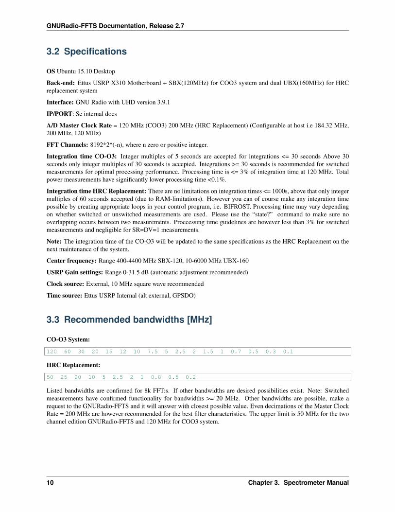
OS Ubuntu 15.10 Desktop
Back-end: Ettus USRP X310 Motherboard + SBX(120MHz) for COO3 system and dual UBX(160MHz) for HRCreplacement system
Interface: GNU Radio with UHD version 3.9.1
IP/PORT: Se internal docs
A/D Master Clock Rate = 120 MHz (COO3) 200 MHz (HRC Replacement) (Configurable at host i.e 184.32 MHz,200 MHz, 120 MHz)
FFT Channels: 8192*2^(-n), where n zero or positive integer.
Integration time CO-O3: Integer multiples of 5 seconds are accepted for integrations <= 30 seconds Above 30seconds only integer multiples of 30 seconds is accepted. Integrations >= 30 seconds is recommended for switchedmeasurements for optimal processing performance. Processing time is <= 3% of integration time at 120 MHz. Totalpower measurements have significantly lower processing time <0.1%.
Integration time HRC Replacement: There are no limitations on integration times <= 1000s, above that only integermultiples of 60 seconds accepted (due to RAM-limitations). However you can of course make any integration timepossible by creating appropriate loops in your control program, i.e. BIFROST. Processing time may vary dependingon whether switched or unswitched measurements are used. Please use the “state?” command to make sure nooverlapping occurs between two measurements. Proccessing time guidelines are however less than 3% for switchedmeasurements and negligible for SR=DV=1 measurements.
Note: The integration time of the CO-O3 will be updated to the same specifications as the HRC Replacement on thenext maintenance of the system.
Center frequency: Range 400-4400 MHz SBX-120, 10-6000 MHz UBX-160
USRP Gain settings: Range 0-31.5 dB (automatic adjustment recommended)
Clock source: External, 10 MHz square wave recommended
Time source: Ettus USRP Internal (alt external, GPSDO)
3.3 Recommended bandwidths [MHz]
CO-O3 System:
120 60 30 20 15 12 10 7.5 5 2.5 2 1.5 1 0.7 0.5 0.3 0.1
HRC Replacement:
50 25 20 10 5 2.5 2 1 0.8 0.5 0.2
Listed bandwidths are confirmed for 8k FFT:s. If other bandwidths are desired possibilities exist. Note: Switchedmeasurements have confirmed functionality for bandwidths >= 20 MHz. Other bandwidths are possible, make arequest to the GNURadio-FFTS and it will answer with closest possible value. Even decimations of the Master ClockRate = 200 MHz are however recommended for the best filter characteristics. The upper limit is 50 MHz for the twochannel edition GNURadio-FFTS and 120 MHz for COO3 system.
10 Chapter 3. Spectrometer Manual

GNURadio-FFTS Documentation, Release 2.7
3.4 List of commands
Communication with the FFTS is handled by a socket server. Invalid commands will return an error message. Thefollowing commands are accepted.:
command valuee.gconf:fft:channels 8192
Control:
meas:init #initilize measurementmeas:adjust #set gain automatically, se code explanation for detailed informationmeas:stop #abort measurementconf:usrp:bw #configure Ettus USRP bandwidthconf:time:obs #integration timeconf:fft:channels #configure FFT channelsconf:usrp:cfreq #configure center frequencyconf:usrp:gain #manual gain setting
State variables:
state? #state of spectrometer i.e. integrating, adjusting, readyread:settings? #returns configured settings and general informationconf:usrp:bw? #return configured bandwidthconf:usrp:gain? #return USRP gainconf:usrp:cfreq? #return center frequencyconf:fft:channels? #return FFT channelsconf:time:obs? #return set integration time
Read data CO-O3:
meas:read:sig? #read signal spectrummeas:read:ref? #read reference spectrummeas:read:sr? #read signal-reference spectrummeas:read:srr? #read (signal-reference)/reference spectrummeas:read:hist? #read sample values from latest meas:adjust, plot in a histogram to observe the sample distribution
Read data HRC Replacement: (Replace x with desired channel i.e. 0 or 1)
meas:read:sig_chx? #read signal spectrummeas:read:ref_chx? #read reference spectrummeas:read:sr_chx? #read signal-reference spectrummeas:read:srr_chx? #read (signal-reference)/reference spectrummeas:read:hist_chx? #read sample values from latest meas:adjust, plot in a histogram to observe the sample distribution
3.5 Effective bandwidth and offsets
The figure shows an example of a power spectrum at 120 MHz. Observe the filter roll off at band edges, implies thateffective bandwidth is less than theoretical set bandwidth. In this case a configured bandwidth of 120 MHz quadraturereturns approximately an effective bandwidth of 105 MHz. Ettus lists an effective bandwidth of approximately 80%of the Nyquist bandwidth which seems to be in accordance with the experimental results. E.g a set bandwidth of 20MHz (+-10MHz from center) will result in an effective bandwidth of approximately 16 MHz (+-8MHz from center).Raw data may contain a center spike due to DC offset in the A/D converters, as shown in the figure. Interpolate thespike to obtain a clean spectrum.
3.4. List of commands 11

GNURadio-FFTS Documentation, Release 2.7
12 Chapter 3. Spectrometer Manual

CHAPTER 4
Code explanation
This section will give a brief overview of the implementation and the the main python classes, for details please gohere. The software consists of one socket server module, Server.py, and four classes, Measurement.py, Analyze.py,Receiver.py and finally Finalize.py. I have been inspired by the SALSA system, created by Eskil Varenius, and youwill find similarites in some modules in the class Analyze.py. The code for the SALSA system can be found here.
4.1 USRP_start.sh
This is a optimization and initialization script for the GNURadio-FFTS. Creates RAMDisk for sampled data, optimizesGNURadio by configuring network buffers and starts the PCIE interface as well as the FFTS.
#!/bin/bash#Title: Ettus USRP optimization and storage init#Author: Simon Olvhammar
#Create and mount RAMDisksudo mkdir /tmp/ramdisksudo chmod 777 /tmp/ramdisksudo mount -t tmpfs -o size=16384M tmpfs /tmp/ramdisk
# Configure Network Bufferssudo sysctl -w net.core.rmem_max=33554432sudo sysctl -w net.core.wmem_max=33554432
# Initalize Ettus USRP PCIe driverssudo ~/bin/niusrprio-installer/niusrprio_pcie start
#Message to Userecho "Ettus USRP PCIe drivers activated"echo "RAMDisk is 8GB in size and located at /tmp/ramdisk"echo "Starting GNURadio-FFTS..."#Start FFTSpython /home/olvhammar/GNURadio-FFTS/Software_HRC/Server.py
4.2 Server.py
This module is a socket server used to communicate with the receiver and basically just handles commands. The codeis pretty much self explanatory and can be found at the GITHUB pages under Olvhammar/GNURadio-FFTS.
13

GNURadio-FFTS Documentation, Release 2.7
4.3 Measurement.py
This is the most important class in the application since this is the base for the Dicke-switching. This class controlsthe Gnuradio flowgraph, Receiver.py, in order to separate the samples corresponding to signal or reference. Separationof the samples is based upon a switch that is controlled by the state of external SR and DV signals that is transmittedto the GPIO of the Ettus X310. It also contains functions such as automatic gain adjustment. The gain adjustment isbased on monitoring the raw samples from the Ettus USRP. The distribution is then checked and gain set accordinglyfor several loops until the full dynamic range of the A/D converter is covered.
4.4 Receiver.py
Receiver.py is the Gnuradio flowgraph and is best explained using a gnuradio-companion flowgraph. The flowgraphis abit simplified and the FFTS includes blocks for e.g. sample monitoring, however that would just clutter the graph,but the fundamentals are displayed. The situation gets a bit more complicated for a two channel setup but the principleis similar. Se Software_HRC/Receiver.py for details.
Fig. 4.1: GNU Radio flow graph describing a general purpose FFT Dicke-switched solution for usage with front-endsimplementing sky, load or frequency switching.
Basically it computes the Fast Fourier Transform (FFT) from the complex sample stream and saves it to file sinks. Ain stream averaging procedure is implemented through a Single Pole IIR filter. The transfer function can be describedby:
y(n) = (1-G)y(n-1) + Gx(n)
Which acts as a cheap and convenient way to perform integration. However it does not contain any decimation ofit’s own why a keep 1 in N block is introduced. Consider the case of a complex sampling rate 120 MSps and a8192 channel FFT produces approximately 14.6e3 FFT/s. Setting G=1/20 and N=1/G the output of the keep 1 in Nblock is instead only 732 FFTs/s. Thus the implemented python long term integrator stress is greatly reduced alongwith processing times. For switched measurements it is however extremely important to make a good tradeoff in theselection of G due to the introduced delay. Ideally a switched measurement should use very small 1/G values. It ishowever great for SR=DV=1 measurements where G, with great benefits, can be very small.
The stream selector at the sink side is fundamental for the Dicke-switching implementation. The stream will beswitched based on the state of RF input. This state, signal or reference, is controlled by an external switch and it willtransmit this information to the GPIO front panel. How this is done in Python can be seen in Measurement.py.
14 Chapter 4. Code explanation
GNURadio-FFTS Documentation, Release 2.7
4.5 Analyze.py
This class stacks all FFT data and performs averaging. The switched data is stacked using the function pool.map tobetter utilize the cores and lower the processing time:
def stack_all_data(self, files):pool = Pool(processes=4)spectra = pool.map(self.stack_FFT_file, files)pool.terminate()return spectra
Where self.stack_FFT_file is defined by:
#According to https://github.com/varenius/salsa/tree/master/USRP/usrp_gnuradio_devdef stack_FFT_file(self, infile):
signal = np.memmap(infile, mode = 'r', dtype = np.float32)num_spec = int(signal.size/self.fftSize) #The number of spectra contained in the filelength = num_spec*self.fftSizesignal = signal[0:length] #Convert the array to an even number of spectrasspec = signal.reshape((num_spec, self.fftSize)) #Reshape the array with FFT:s so it can be easily stackedspec = spec.sum(axis=0) #Stack the FFT:sspec = spec/(1.0*num_spec) #Average Spectrumdel signalreturn spec
Which reads the file containing FFT data and returns one averaged FFT. Finally the mean value of the stacked FFTs iscalculated:
def mean(self, spectra):sum_spec = np.sum(spectra, axis=0, dtype = np.float32)return sum_spec/float(len(spectra))
4.6 Finalize.py
This class finalizes the measurement and performs e.g. the final averaging and creates FITS-files according to OSO-standards.
4.7 Improvements and other toughts
Things I would like to improve, any input would be greatly appreciated.
4.7.1 Processing delays
Depending on the desired bandwidth the stacking process can take up to 3% of the total measure time, thus introducinga short processing delay between the measurements. I have greatly reduced the stacking time by the use of threads (i.e.pool.map), however I would like to run the stacking in the background so the stacking procedure can be performedduring runtime. The problem is however restriced to switched measurements since it produces alot of individual filesthat need be stacked. This is not the case for SR=DV=1.
4.5. Analyze.py 15

GNURadio-FFTS Documentation, Release 2.7
4.7.2 Alternatives to sync bus switching
Currently the mixer in the front-end of the system is controlled by a sync bus, which in turn sends the state signals(sig or ref) to the GPIO of the Ettus USRP. The optimal method, with GNU Radios unpredictable processing delayin mind, would be to instead having the GNURadio-FFTS software controlling the mixer instead of external systems.This would allow for precise sample timing and thus I would be able to remove short delay I have introduced to makesure FFTs do not overlap.
16 Chapter 4. Code explanation
CHAPTER 5
FPGA implementation using RFNoC
The current GNURadio-FFTS only uses the Kintex 7 FPGA of the Ettus x310 as a standard DDC. The Kintex 7however have a great potential and it would be extremely beneficial to perform e.g. the FFT on the FPGA instead ofthe host-computer. Some of the benefits include lowering the CPU stress and data rates.
5.1 RFNoC
RFNoC (RF Network on Chip) is a relatively new concept in GNURadio which allows for, in relation to rawVHDL/Verilog, an easy FPGA implementation of several functions. Such as:
FFT computations up to 2048 channelsVector IIR averaging filters, extremely useful for FFT outputsKeep one in N function, combined with the IIR filter allows for decimation of the stream and thus data rates
5.2 GNURadio-FFTS RFNoC modification
Code have been develop to implement a RFNoC version of the GNURadio-FFTS described here and right now thereare mainly two points that prevents a update of the system:
- Number of FFT-channels, where max for RFNoC is in practice only 2048 with a theoretical max of 4096 (Xilinx coregen based). At OSO we require atleast 8192 channels to achieve the desired resolution.- RFNoC, at this time, only fully supports ethernet communication.
The ethernet equipment is obviously not the biggest problem since we can aquire that but the FFT is trickier. Thereis basically two things that needs be updated in order for a 8k channel FFT to be implemented in RFNoC. One: theXilinx coregen based FPGA FFT implementation needs to be updated to 8k channels. And secondly the GNURadiodevelopers needs to add support for fragmentation of vectors in RFNoC which is why only 2048 channel FFT ispossible in RFNoC right now. I have however spoken to several of them and an update is expected and it is on theirtodolist. It should also be noted that RFNoC is yet in it’s alpha stage of development rendering instability as possibleproblem as well. I expect that within one year a 8k FFT in RFNoC is implemented and thus the GNURadio-FFTS canbe implemented on the FPGA of the Ettus X310 instead of the host computer. This is useful for the CO-O3 systemswhere high bandwidths are desired, for the HRC replacement system the benefits are small.
17
GNURadio-FFTS Documentation, Release 2.7
18 Chapter 5. FPGA implementation using RFNoC
CHAPTER 6
Results and discussion
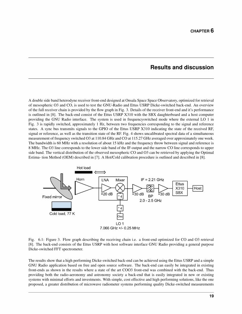
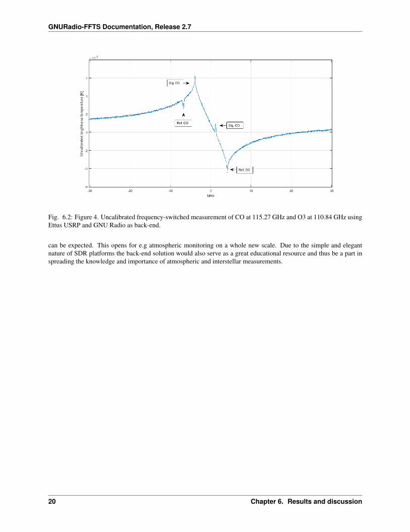
A double side band heterodyne receiver front-end designed at Onsala Space Space Observatory, optimized for retrievalof mesospheric O3 and CO, is used to test the GNU-Radio and Ettus USRP Dicke-switched back-end. An overviewof the full receiver chain is provided by the flow graph in Fig. 3. Details of the receiver front-end and it’s performanceis outlined in [8]. The back-end consist of the Ettus USRP X310 with the SBX daughterboard and a host computerproviding the GNU Radio interface. The system is used in frequencyswitched mode where the external LO 1 inFig. 3 is rapidly switched, approximately 1 Hz, between two frequencies corresponding to the signal and referencestates. A sync bus transmits signals to the GPIO of the Ettus USRP X310 indicating the state of the received RF,signal or reference, as well as the transition state of the RF. Fig. 4 shows uncalibrated spectral data of a simultaneousmeasurement of frequency switched O3 at 110.84 GHz and CO at 115.27 GHz averaged over approximately one week.The bandwidth is 60 MHz with a resolution of about 15 kHz and the frequency throw between signal and reference is8 MHz. The O3 line corresponds to the lower side band of the IF-output and the narrow CO line corresponds to upperside band. The vertical distribution of the observed mesospheric CO and O3 can be retrieved by applying the OptimalEstima- tion Method (OEM) described in [7]. A Hot/Cold calibration procedure is outlined and described in [8].
Fig. 6.1: Figure 3. Flow graph describing the receiving chain i.e. a front-end optimized for CO and O3 retrieval[8]. The back-end consists of the Ettus USRP with host software interface GNU Radio providing a general purposeDicke-switched FFT spectrometer.
The results show that a high performing Dicke-switched back-end can be achieved using the Ettus USRP and a simpleGNU Radio application based on free and open source software. The back-end can easily be integrated in existingfront-ends as shown in the results where a state of the art COO3 front-end was combined with the back-end. Thusproviding both the radio-aeronomy and astronomy society a back-end that is easily integrated in new or existingsystems with minimal efforts and investments. With simple, cost effective and high performing solutions, like the oneproposed, a greater distribution of microwave radiometer systems performing quality Dicke-switched measurements
19
GNURadio-FFTS Documentation, Release 2.7
Fig. 6.2: Figure 4. Uncalibrated frequency-switched measurement of CO at 115.27 GHz and O3 at 110.84 GHz usingEttus USRP and GNU Radio as back-end.
can be expected. This opens for e.g atmospheric monitoring on a whole new scale. Due to the simple and elegantnature of SDR platforms the back-end solution would also serve as a great educational resource and thus be a part inspreading the knowledge and importance of atmospheric and interstellar measurements.
20 Chapter 6. Results and discussion

CHAPTER 7
References
[1] J. Mitola, The software radio architecture, IEEE Commun. Mag., vol 33, no 5, pp. 26-38, May 1995
[2] P. Kildal, A. Hussain, B. Einarsson, MIMO OTA testing of a communication system using SDRs in a reverberationchamber, IEE Antennas Propag. Mag., vol 57, no 2, pp. 44-53, April 2015
[3] P. Cruz et al., Designing and testing software-defined radio, IEEE Microwave Mag. , vol 11, no 4, pp. 83-94, June2010.
[4] National Instruments Corporation, Austin, TX, USA. [Online]. Available: http://www.ni.com
[5] Ettus Research, a National Instruments Company. [Online]. Available: http://www.ettus.com
[6] GNU Radio Website. [Online]. Available: http://www.gnuradio.org
[7] P. Forkman et al., Six years of mesospheric CO estimated from ground-based frequency-switched microwaveradiometry at 57◦ N compared with satellite instruments, Atmos. Meas Tech., 5, 2827-2841, 2012.
[8] P. Forkman et al., A compact receiver system for simultaneous measurements of mesospheric CO and O3, Geosci.Instrum. Method. Data syst. Discuss., 5, 311-361, 2015.
21

GNURadio-FFTS Documentation, Release 2.7
22 Chapter 7. References

CHAPTER 8
Appendix
8.1 Ettus USRP X310 Data sheet
8.2 UBX-160 Daughterboard Data sheet
23
GNURadio-FFTS Documentation, Release 2.7
24 Chapter 8. Appendix

GNURadio-FFTS Documentation, Release 2.7
8.2. UBX-160 Daughterboard Data sheet 25
GNURadio-FFTS Documentation, Release 2.7
26 Chapter 8. Appendix

GNURadio-FFTS Documentation, Release 2.7
8.2. UBX-160 Daughterboard Data sheet 27

GNURadio-FFTS Documentation, Release 2.7
28 Chapter 8. Appendix
CHAPTER 9
Indices and tables
• genindex
• modindex
• search
29
Recommended